
An Analytical Method Evaluating the Evolution of Group Effect for Vertically Loaded Pile Groups Subjected to Tunnel Excavation

Abstract
:1. Introduction
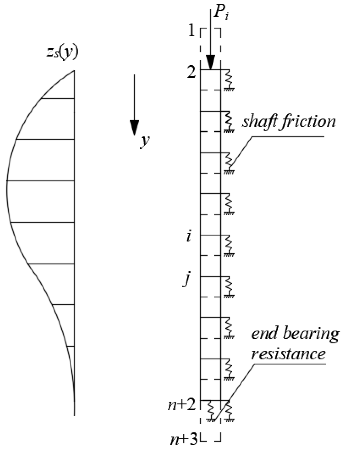
2. Methodology
2.1. Calculation of
2.2. Calculation of
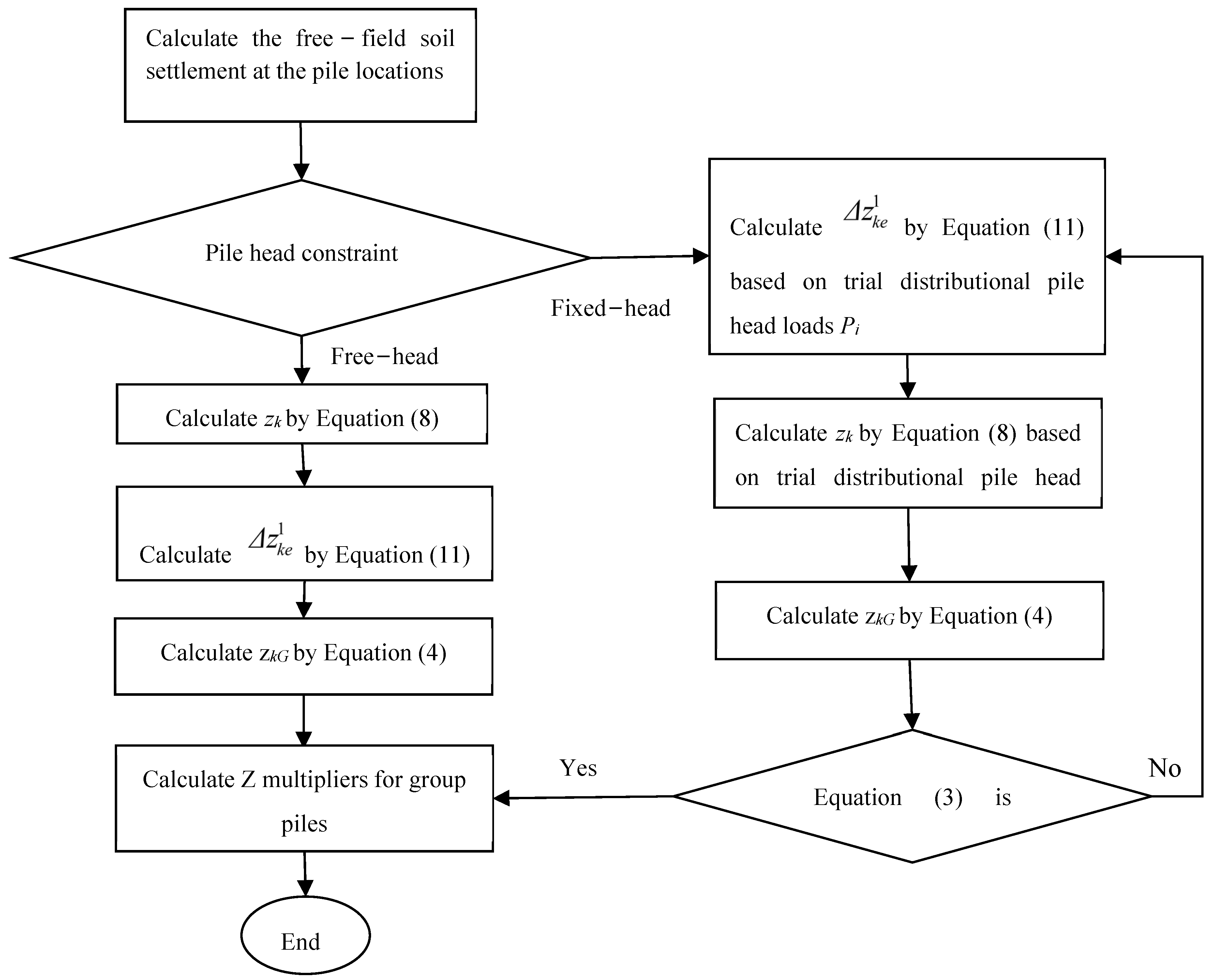
2.3. Calculation Procedure
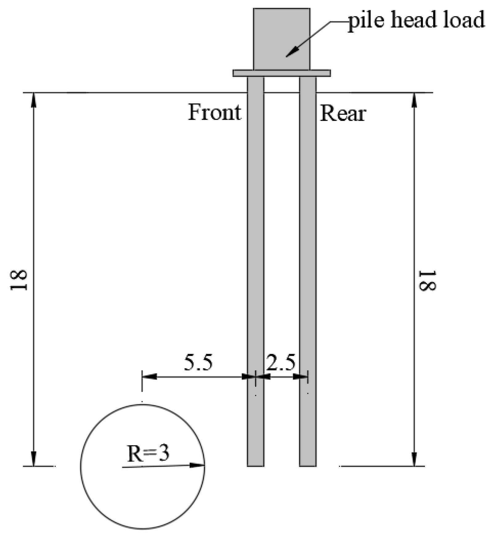
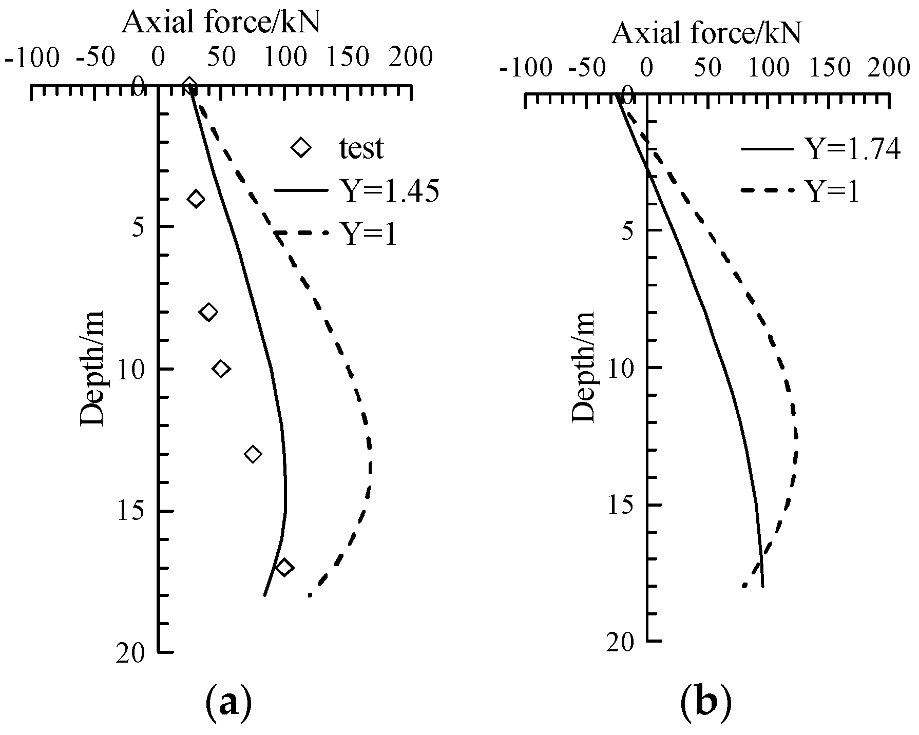
3. Verification
4. Discussion
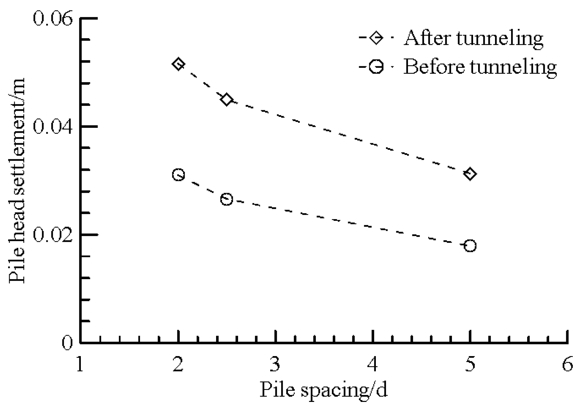
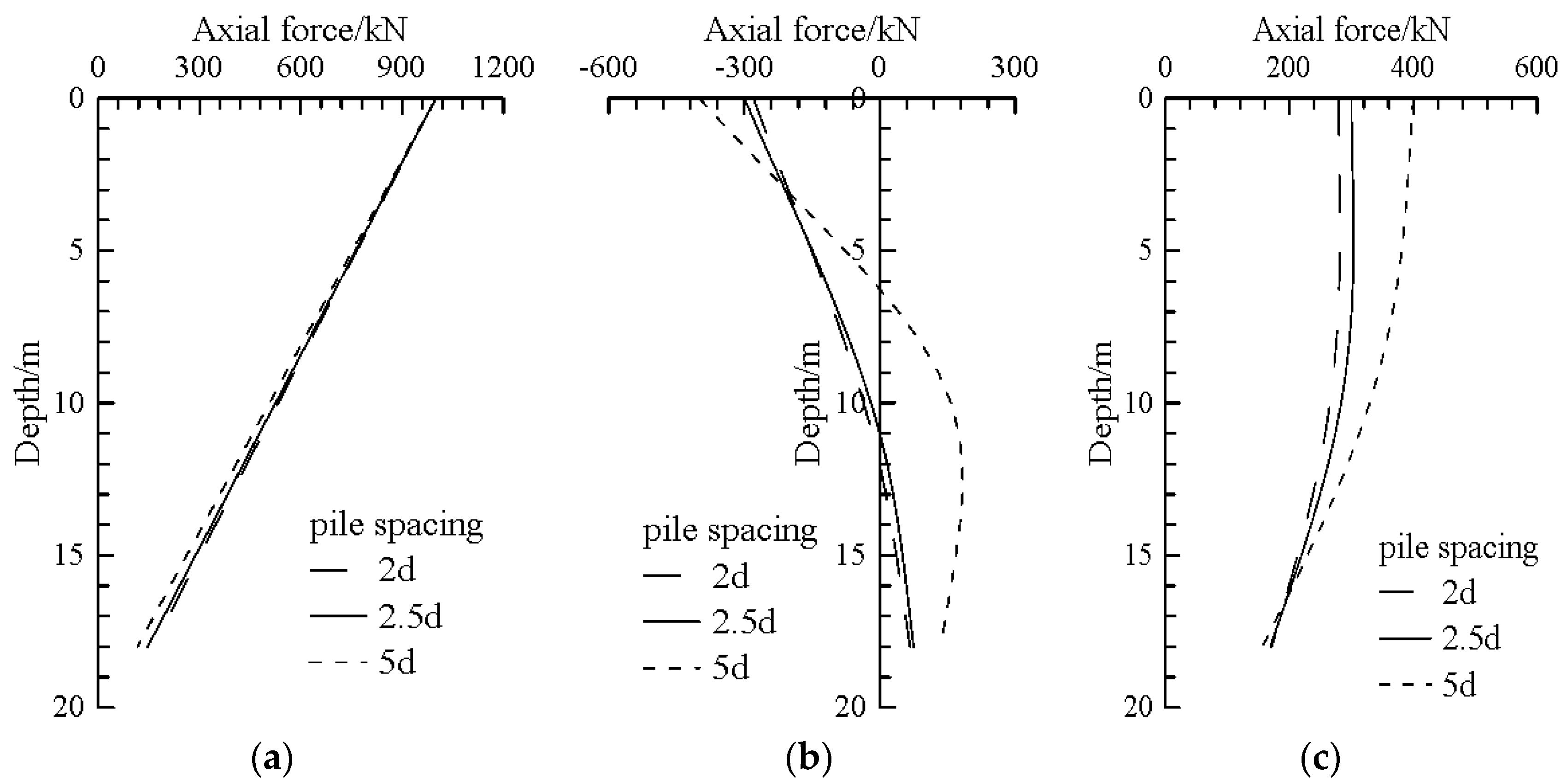
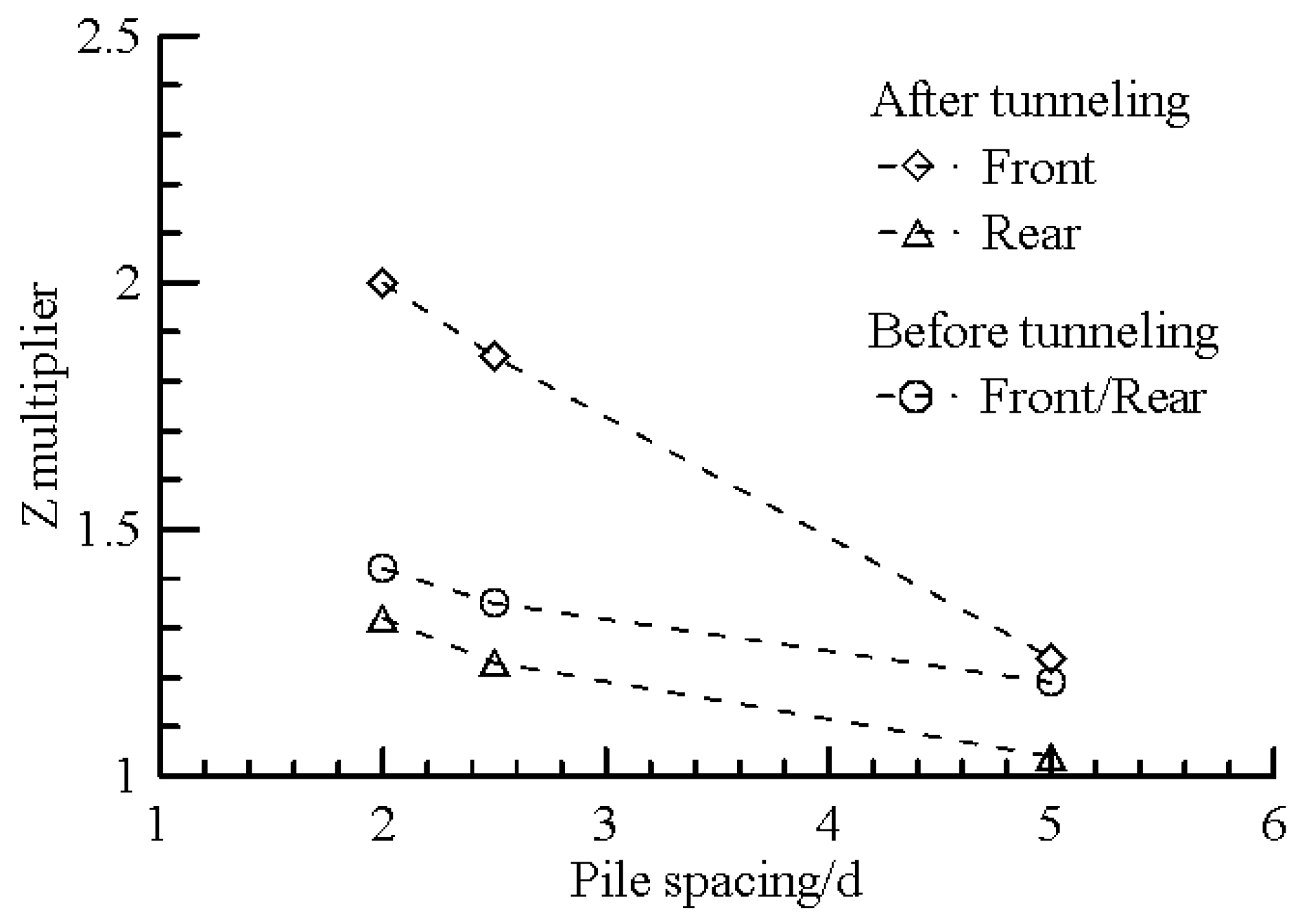
4.1. Influence of Pile Spacing
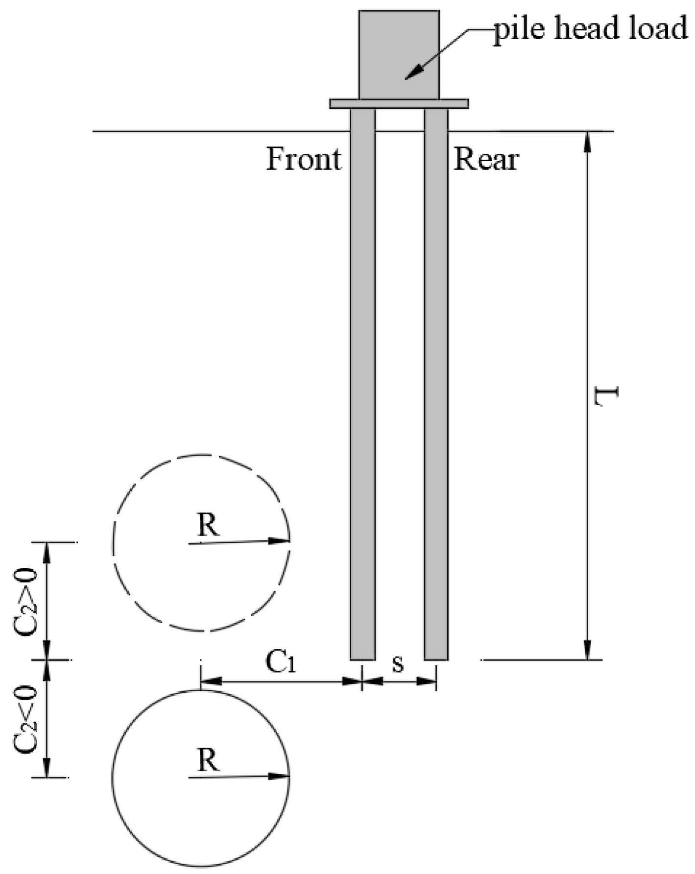
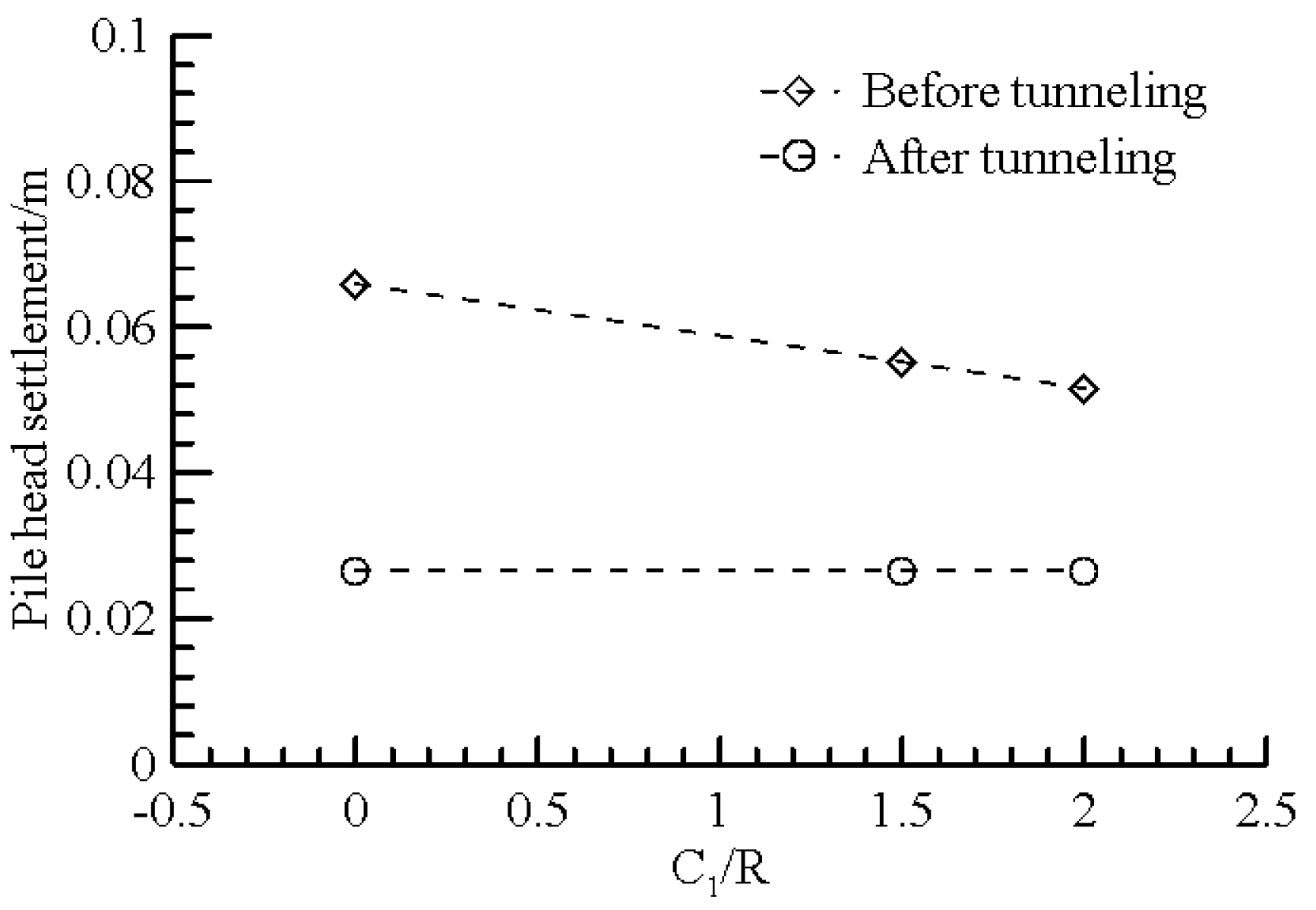
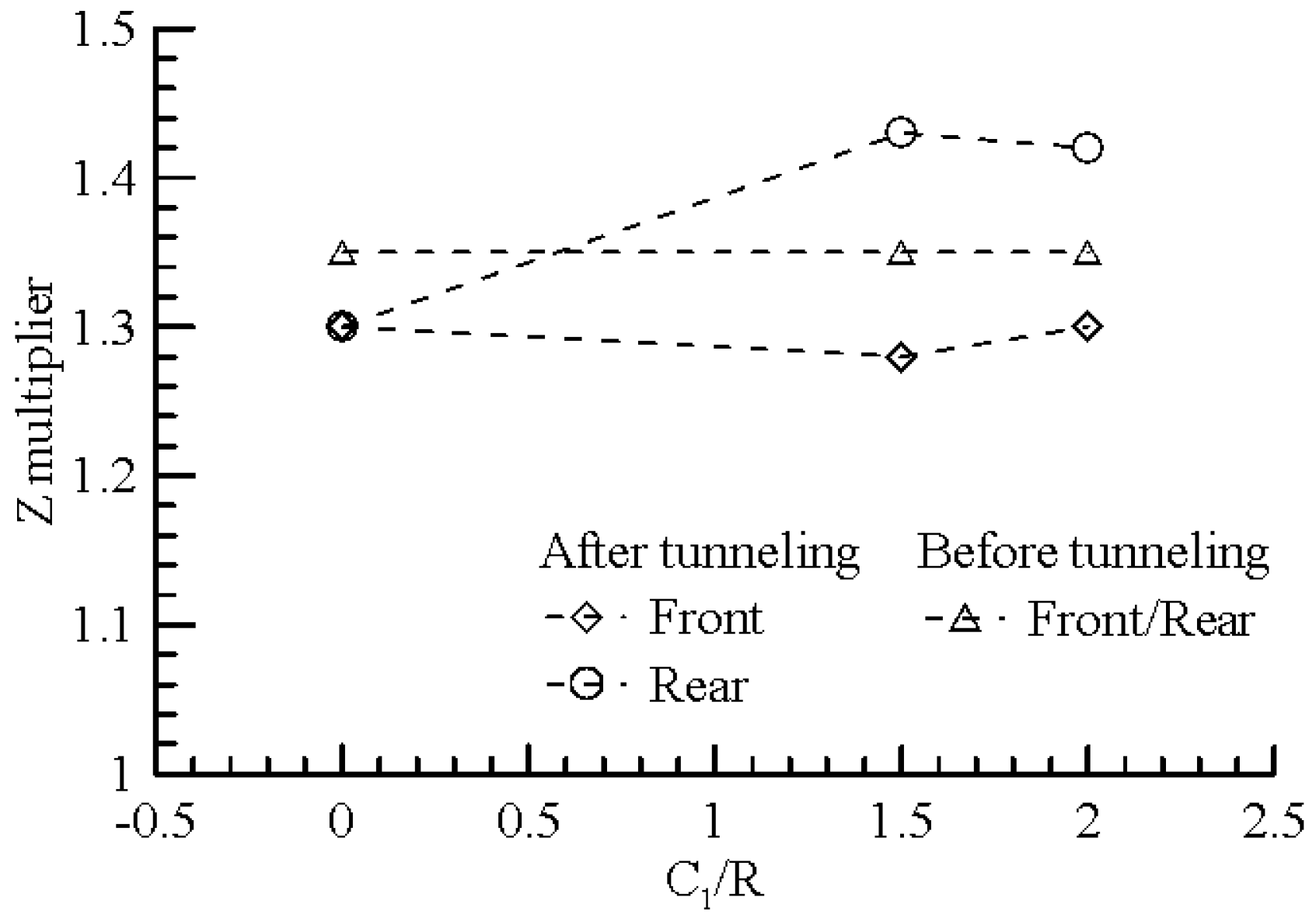
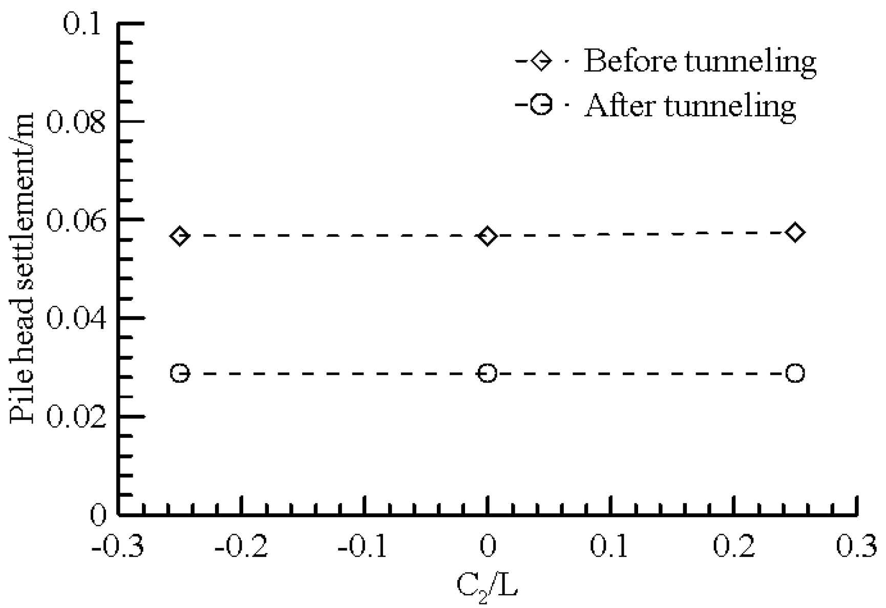
4.2. Influence of Lateral Clearance between the Front Row Piles and Tunneling
4.3. The Influence of Vertical Distance between the Pile Tip and Tunneling
5. Conclusions
Author Contributions
Funding
Institutional Review Board Statement
Informed Consent Statement
Data Availability Statement
Conflicts of Interest
References
- Zhang, R.; Zheng, J.; Pu, H.; Zhang, L. Analysis of excavation-induced responses of loaded pile foundations considering unloading effect. Tunn. Underg. Space Technol. 2011, 26, 320–335. [Google Scholar] [CrossRef]
- JTS167-4-2012; Code For Pile Foundation for Harbor Engineering. Ministry of Transport of People’s Republic of China: Beijing, China, 2012.
- UFC3-220-01; Geotechnical Engineering. U.S. Army Corps of Engineers: Washington, DC. USA, 2012.
- Poulos, H.G.; Davis, E.H. Pile Foundation Analysis and Design; Taipei Rainbow Bridge Book Co.: Taiwan, China, 1980. [Google Scholar]
- Xu, K.J.; Poulos, H.G. 3-D elastic analysis of vertical piles subjected to “passive’’ loadings. Comput. Geotech. 2001, 28, 349–375. [Google Scholar] [CrossRef]
- Chow, Y.K. Analysis of vertically loaded pile groups. Int. J. Numer. Anal. Methods Geomech. 1986, 10, 59–72. [Google Scholar] [CrossRef]
- Randolph, M.F.; Wroth, C.P. Analysis of deformation of vertically loaded piles. J. Geotech. Engrg Div. ASCE 1978, 104, 1465–1488. [Google Scholar] [CrossRef]
- Zhang, Q.; Liu, S.; Zhang, S.; Zhang, J.; Wang, K. Simplified non-linear approaches for response of a single pile and pile groups considering progressive deformation of pile-soil system. Soils Found. 2016, 56, 473–484. [Google Scholar] [CrossRef]
- Hong, Y.; Soomro, M.; Ng, C. Settlement and load transfer mechanism of pile group due to side-by-side twin tunneling. Comput. Geotech. 2015, 64, 105–119. [Google Scholar] [CrossRef]
- Soomro, M.A.; Hong, Y.; Ng, C.W.W.; Lu, H.; Peng, S. Load transfer mechanism in pile group due to single tunnel advancement in stiff clay. Tunn. Undergr. Space Technol. 2015, 45, 63–72. [Google Scholar] [CrossRef]
- Song, G.; Marshall, A.M. Tunnel-piled structure interaction: Numerical simulation of hybrid centrifuge tests. Compu. Geotech. 2021, 140, 104477. [Google Scholar] [CrossRef]
- Focht, J.A.; Koch, K.J. Rational Analysis of the Lateral Performance of Offshore Pile Groups; OTC: Dallas, TX, USA, 1973. [Google Scholar] [CrossRef]
- API R P 2A-WSD; Recommended Practice for Planning, Designing and Constructing Fixed Offshore Platforms-Working Stress Design. American Petroleum Institute: Washington, DC, USA, 2011.
- Huang, M.; Zhang, C.; Li, Z. A simplified analysis method for the influence of tunneling on grouped piles. Tunn. Undergr. Space Technol. 2009, 24, 410–422. [Google Scholar] [CrossRef]
- Franza, A.; Zheng, C.; Marshall, A.; Jimenez, R. Investigation of soil-pile-structure interaction induced by vertical loads and tunneling. Compu. Geotech. 2021, 139, 104386. [Google Scholar] [CrossRef]
- Loganathan, N.; Poulos, H.G. Analytical prediction for tunneling-induced ground movements in clays. J. Geotech. Geoenviron. Eng. 1998, 124, 846–856. [Google Scholar] [CrossRef]
- Leung, Y.F.; Soga, K.; Lehane, B.M.; Klar, A. Role of linear elasticity in pile group analysis and load test interpretation. J. Geotech. Geoenviron. Engrg. ASCE 2010, 136, 1686–1694. [Google Scholar] [CrossRef]
- Verruijt, A.; Booker, J.R. Surface Settlements Due to Deformation of a Tunnel in an Elastic Half Plane; Geotechnique: London, UK, 1996; Volume 46, pp. 753–756. [Google Scholar]
- Loganathan, N.; Poulos, H.G.; Stewart, D.P. Centrifuge model testing of tunneling-induced ground and pile deformation. Geotechnique 2000, 50, 293–294. [Google Scholar] [CrossRef]
- Goh, A.T.C.; Teh, C.I.; Wong, K.S. Analysis of piles subjected to embankment induced soil movements. J Geotech. Geoenviron. Engrg. ASCE 1997, 123, 383–386. [Google Scholar] [CrossRef]
- Wong, K.S.; Teh, C.I. Negative skin friction on piles in layered soil deposits. J. Geotech. Eng. 1995, 121, 457–465. [Google Scholar] [CrossRef]
- Vesic, A.S. Ultimate loads and settlements of deep foundations in sand. In Proceedings of the Symposium on Bearing Capacity and Settlement of Foundation, Durham, UK, 15 June 1998; 1965; pp. 53–68. [Google Scholar]
- He, S.; Lai, J.; Li, Y.; Wang, K.; Wang, L.; Zhang, W. Pile group response induced by adjacent shield tunneling in clay: Scale model test and numerical simulation. Tunn. Underg. Space Technol. 2022, 120, 104039. [Google Scholar] [CrossRef]


| Pile Row | Before Tunneling | After Tunneling |
|---|---|---|
| Front | 1.52 | 1.45 |
| Rear | 1.52 | 1.74 |
| Case No. | s | C1/R | C2/L |
|---|---|---|---|
| 1 | 2 | 1.5 | 0.25 |
| 2 | 2.5 | 1.5 | 0.25 |
| 3 | 5 | 1.5 | 0.25 |
| 4 | 2.5 | 0 | −0.25 |
| 5 | 2.5 | 1.5 | −0.25 |
| 6 | 2.5 | 2 | −0.25 |
| 7 | 2.5 | 1.5 | 0 |
Disclaimer/Publisher’s Note: The statements, opinions and data contained in all publications are solely those of the individual author(s) and contributor(s) and not of MDPI and/or the editor(s). MDPI and/or the editor(s) disclaim responsibility for any injury to people or property resulting from any ideas, methods, instructions or products referred to in the content. |
© 2022 by the authors. Licensee MDPI, Basel, Switzerland. This article is an open access article distributed under the terms and conditions of the Creative Commons Attribution (CC BY) license (https://creativecommons.org/licenses/by/4.0/).
Share and Cite
Fan, Y.; Cai, J.; Wang, J. An Analytical Method Evaluating the Evolution of Group Effect for Vertically Loaded Pile Groups Subjected to Tunnel Excavation. Appl. Sci. 2023, 13, 517. https://doi.org/10.3390/app13010517
Fan Y, Cai J, Wang J. An Analytical Method Evaluating the Evolution of Group Effect for Vertically Loaded Pile Groups Subjected to Tunnel Excavation. Applied Sciences. 2023; 13(1):517. https://doi.org/10.3390/app13010517
Chicago/Turabian StyleFan, Yifei, Jing Cai, and Jianhua Wang. 2023. "An Analytical Method Evaluating the Evolution of Group Effect for Vertically Loaded Pile Groups Subjected to Tunnel Excavation" Applied Sciences 13, no. 1: 517. https://doi.org/10.3390/app13010517
APA StyleFan, Y., Cai, J., & Wang, J. (2023). An Analytical Method Evaluating the Evolution of Group Effect for Vertically Loaded Pile Groups Subjected to Tunnel Excavation. Applied Sciences, 13(1), 517. https://doi.org/10.3390/app13010517