1. Introduction
Nowadays, the meshing noise of the gear systems, which are widely used power and motion transmission devices, has attracted widespread attention from experts in the field. With the development of machinery manufacturing and processing technology, especially the emergence of new technologies such as additive manufacturing [
1,
2,
3], machinery processing accuracy can be guaranteed [
4]. Then, the structure optimization of gears, such as spoke hole structures, can provide a new idea for reducing meshing noise.
The meshing noise of the gears is mainly caused by meshing stiffness shock and meshing error without considering the bending deformation of the gear shaft. This paper mainly discusses the previous influencing factor.
The changes in the meshing teeth numbers during the transmission process will result in the changes of the contact line length. Then, stiffness shock occurs during the periodic meshing of gears. The periodic vibration of the gears along the meshing line caused by the stiffness shock will promote the generation of noise. To control the meshing stiffness and the stiffness fluctuation during gear transmission is an effective way to restrain the periodic vibration.
The meshing stiffness is related to many parameters of the gear, including the number of teeth, modulus, displacement factor, etc. It has been studied by previous scholars that the meshing performance of the gears can be improved by optimizing the structural parameters [
5].
Significant efforts have been devoted to studying gear meshing. Based on the finite element method, the accuracy of gear meshing calculations is achieved by Coy [
6]. Then, the meshing stiffness can be obtained by the numerical calculation method [
7] and the finite element method [
8]. In addition, the influencing factors of meshing stiffness, such as the profile errors [
9], the tooth tip radius [
10], and the rotation speed [
11], were verified. For gear meshing noise, the mapping relationship between mesh stiffness and noise is established by considering the gear rim thickness [
12], pressure angle and helix angle [
13], bearing load [
14], and other parameters.
However, research on the influence of the gear spoke structure on gear meshing noise has rarely been reported. The spoke is an important structure of the gear, and it will affect the gear meshing noise. The spoke hole structure was proposed to solve the above problems. This paper aims to analyze the influence of the gear spoke hole numbers on the meshing stiffness and noise under the condition of constant speed and resistance moment. The results show that more spoke holes lead to less meshing stiffness and less stiffness fluctuation. In addition, it was observed from the BEM acoustic simulation that the meshing stiffness is the dominate factor for noise. Less meshing stiffness will result in louder noise according to the correspondence between the gear spoke hole numbers, stiffness, and noise. The experiment shows the same trend through measuring the vibration of the reducer outer box caused by the change in spoke hole numbers. In summary, more spoke holes result in louder noise, and the growth trend will decrease slightly with the increase in spoke hole numbers, which agrees with the simulation. The results represent a reasonable method to design the gear spoke structure for reducing the meshing noise.
2. Gear Meshing Model
The gear meshing model can be regarded as a simple dynamic system by neglecting the deformation of the shaft system in the traditional rigid contact theory. That is, only the rotation of the two gears around each axis is considered. The traditional rigid contact theoretical model is shown in
Figure 1 [
15].
The dynamic equations of the above model give [
10].
where
is the normal offset value;
is the base circle rotation angle of the driving gear;
is the base circle diameter of the driving gear;
is the base circle rotation angle of the driven gear;
is the base circle diameter of the driven gear;
is the meshing stiffness of the gears with the rigid spokes;
is the meshing damping;
is the driven gear torque; and
is the driving gear torque.
As is known, gear meshing stiffness is affected by various factors. In addition, the coupling relationship of the factors and their influence on meshing stiffness have not been studied by the contact model in previous pieces of research.
This paper aims to determine the influence of gear spoke numbers on the meshing stiffness and noise. The first task of the research is to add the gear spoke stiffness to the meshing stiffness of the gears with the rigid spokes . Thus, the gear with the spoke can be decomposed into the flexible gear with the rigid no-hole spoke and the flexible spoke in the analysis of the meshing stiffness.
The inner boundary force of the flexible gear with the rigid no-hole spoke can be regard as the boundary condition of the flexible spoke by considering the coupling relationship between the two structures. The model is shown in
Figure 2.
Therefore, the dynamic equations of the gears with spokes are [
16]
where
and
are the moment of inertia and the torsional stiffness of the flexible gear with rigid no-hole spoke, respectively;
and
are the moment of inertia of and the torsional stiffness of the flexible spoke, respectively;
is the torque of the rigid spokes given by the flexible gear with the rigid no-hole spoke; and
is the torque of the driven gear given by the driving gear.
Since the gear with the spoke had been decomposed into the flexible gear with the rigid no-hole spoke and the flexible spoke, the force and displacement of the gear meshing are basically annular. Thus, the gear model can be divided by the FE method along the annular shape. The torsional angle of the gear unit is distributed to each ring, as shown in
Figure 3.
The dynamic equation of the flexible gear with the rigid no-hole spoke can be obtained by taking the stiffness and moment of inertia parameters of each ring into the Equation (4), which gives:
where
are the torque between the rings;
are the moment of inertia of each ring;
are the rotation angles of each ring; and
are the torsional stiffness between the rings.
The force of the driven gear
given by the driving gear can be expressed by the rotation angle difference on the base circle, which gives:
The
can be regard as the boundary conditions of the dynamic equation of the flexible spoke, which is obtained by taking the corresponding stiffness and moment of inertia parameters at each ring into the Equation (5), which gives:
where the subscript
represents the corresponding parameters of the flexible spoke. The base circle deformation of the gear can be obtained by:
where
is the base circle tangential displacement of the flexible spoke;
is the base circle tangential displacement difference of the flexible gear with the rigid no-hole spoke;
is the base circle rotation angle of the driven flexible gear with the rigid no-hole spoke; and
is the comprehensive tangential displacement difference.
The meshing stiffness of the gears gives:
3. Simulation of Gear Meshing Stiffness
3.1. Gear Meshing Stiffness
The quasi-static method is used for gear meshing. According to gear dynamics Equation (1)–(3), the meshing stiffness gives:
where
is normal force of the meshing tooth surface.
Then, the meshing stiffness of the gears with different spokes can be solved by giving the fixed torque and the fixed rotational speed to the driven gear and driving gear, respectively. The other parameters of the gears are shown in
Table 1:
3.2. Influence of Spoke Cycle Structure on the Gear Meshing Stiffness
Some scholars have demonstrated that the meshing stiffness of the gears with no spokes will cycle with the meshing period during meshing. However, the gears, which with spokes and the spoke cycle structure do not coincide with the gear stiffness, have not been studied. In the paper, the stiffness of the gear with the spoke in one meshing cycle is calculated. In addition, the focus of
Section 3.2 is to judge the influence of spoke cycle structure on gear meshing stiffness through the simulation of large rotation angles. This can be the basis of the following simulation of small rotation angles.
The material properties are shown in the
Table 2:
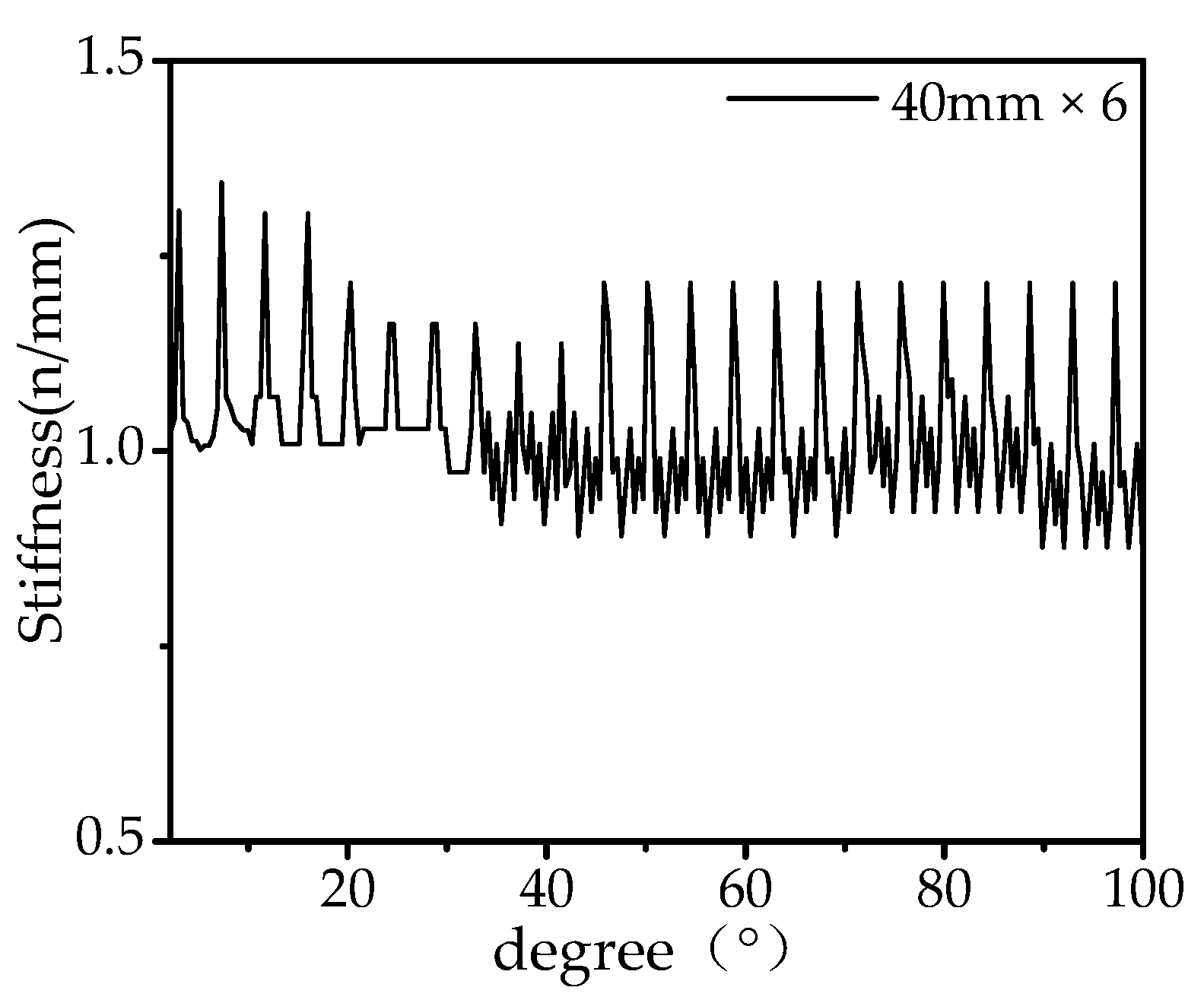
The gear spoke with six holes (diameter = 40 mm) is selected to simulate the meshing stiffness. The SOLID 185 element and the regular hexagon mesh type are used to establish the numerical model. The gear meshing contact type is defined as frictionless, and the penetration tolerance value is 0.0005 m. The constant speed of the driving gear is set to 1.56 rad/s and the constant torque of the driven gear is set to 1000 N·m. The step end time is 0.5 s and the number of substeps is a fixed value of 500. The meshing stiffness of the gears in one cycle was analyzed and the result is shown in
Figure 4 and
Figure 5.
Figure 4 shows that the spoke cycle structure has little effect on the meshing stiffness. In addition, the gear deformation in meshing is basically maintained as a circle.
3.3. Influence of Gear Spoke Hole Numbers on Gear Meshing Stiffness
The three kinds of gear spokes with six holes, three holes and no holes are selected to simulate the meshing stiffness, and the diameter of all the holes is 40 mm, as shown in
Figure 6.
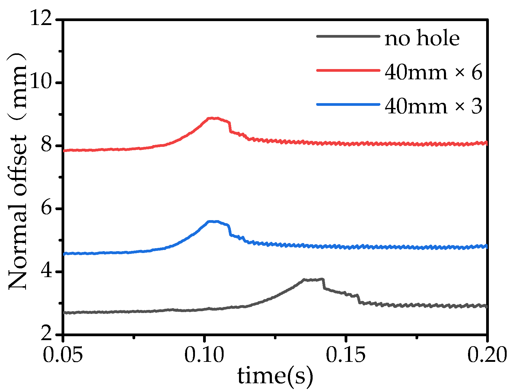
The step end time is set as 0.2 s and the other settings are consistent with
Section 3.2. The normal offset value can be calculated, as shown in
Figure 7:
As the spoke hole numbers increase, the normal offset value shows a clear upward trend and its fluctuation trend almost remains constant during the change in the meshing teeth numbers. The difference in the normal offset value between no holes and three holes is 1.48, which roses to 3.28 between three holes and six holes, as shown in
Figure 7.
According to Equation (12), the meshing stiffness of the gears with three kinds of spokes is shown in
Figure 8.
It is clear that the increase in the spoke hole numbers will result in the decrease in the meshing stiffness and the weakening of the meshing stiffness fluctuation due to the constant of the normal offset fluctuation. The difference in the meshing stiffness between no holes and three holes is 0.64, which falls to 0.39 between three holes and six holes, as shown in
Figure 8.
3.4. The Meshing Noise under Different Gear Spoke Hole Numbers
The quasi-static dynamic result was imported into the LMS Virtual.Lab (Seattle, WA, USA) and the noise caused by the change in the meshing stiffness was studied through the acoustic boundary element method. The other structures of the gears and the bending of the gear shaft will both affect the meshing stiffness. In the paper, only the meshing noise is analyzed and other influencing factors have been ruled out. The quasi-static simulation results are taken into acoustic simulation as the vibration source. The acoustic boundary element is a 2.5 mm-long element envelope mesh. In addition, the modal type is the direct method, and the calculation zone is external region only.
From the above simulation, it is clear that the mesh stiffness and stiffness fluctuation have opposite effects on the noise. Thus, it is difficult to judge the comprehensive influence of stiffness and stiffness fluctuation on the noise. Then, the relationship between the spoke hole numbers and the meshing noise is carried out by acoustic simulation.
As is known, the main frequency of gear vibration is close to its frequency of low-order modals. Thus, the frequency of the main sound pressure levels can be obtained by analyzing the modals of the gear. Since the influence of the gear spoke hole numbers on the gear modal is not particularly obvious, only the natural frequency distribution of the meshing for the gear spoke with six holes has been completed here.
Figure 9 shows that the main frequency of the gears is 132.34 hz. In addition, the vibration form of the gears is rotating around their own axis.
Actually, the meshing noise of the gears is not obvious due to the large stiffness and small size in the simulation. The main sound pressure field solved here is within the range of 500 mm in order to highlight the change in gear noise. The sound pressure changes of each gear are shown in
Figure 10,
Figure 11 and
Figure 12.
Figure 10,
Figure 11 and
Figure 12 show that the decrease in the stiffness will result in a louder gear meshing noise, but the influence of the stiffness fluctuation on the noise could be neglected. It is clear that the noise field shape extends outward along the gear radius direction and the range of the noise field around the big gear is larger than that of the small gear. The maximum noise is located at the position on the big gear which is far away from the meshing point. In addition, it becomes more obvious as the meshing stiffness decreases.
The frequency response curves of point P, which is located at (50 mm, 150 mm, 0) relative to the meshing point, for the three kinds of spokes are shown in
Figure 13.
Figure 14 shows the normal offset value, the reciprocal of meshing stiffness, and the meshing noise at point P with the frequency of 100 hz. The difference in the point P noise at 100 hz between no holes and three holes is 1.94, which falls to 0.92 between three holes and six holes. In addition, the noise value is positively correlated with the reciprocal of the meshing stiffness and the normal offset value. In summary, more spoke holes result in louder noise.
4. Gear Meshing Stiffness Testing under Different Gear Spoke Hole Numbers
Since sound pressure levels are closely related to the vibration intensity of the main sound contribution plane, the meshing noise can be predicted by measuring the vibration of the contribution plane in the reducer experimental platform.
The adjustable speed motor is used to drive the high-speed shaft. The uniform resistance torque for the low-speed shaft is provided by the electromagnetic brake. In addition, the vibration can be measured by the accelerometers. The experimental platform and the layout of the accelerometers are shown in
Figure 15 and
Figure 16.
The motor speed and the brake current are set to 200 rpm and 0.2 amps, respectively. The vibration of the reducer outer box is measured for the above three gear spoke structures. The accelerations of each point are shown in
Figure 17.
Figure 17 shows that the main vibration frequency is about 6100 hz after removing the high-frequency and low-frequency sign. In addition, the vibration acceleration reduces with the decrease in the gear spoke hole numbers.
The peak differences in the vibration frequency between three kinds of gear spokes at position in and position two agree well with the simulation, as shown in
Table 3. With the increase in the spoke hole numbers, the peak differences decrease about 50%.


