Article

Fast Vibration Reduction Optimization Approach for Complex Thin-Walled Shells Accelerated by Global Proper Orthogonal Decomposition Reduced-Order Model

1
State Key Laboratory of Structural Analysis for Industrial Equipment, Department of Engineering Mechanics, Dalian University of Technology, Dalian 116024, China
2
Expace Technology Co., Ltd., Wuhan 430040, China
3
Military Industry Program Evaluation Center, State Administration of Science, Technology and Industry for National Defence, Beijing 100039, China
4
Institute of Spacecraft System Engineering, China Academy of Space Technology, Beijing 100094, China
*
Author to whom correspondence should be addressed.
Appl. Sci. 2023, 13(1), 472; https://doi.org/10.3390/app13010472
Submission received: 30 November 2022 / Revised: 25 December 2022 / Accepted: 27 December 2022 / Published: 29 December 2022

Abstract

:
A fast vibration reduction optimization approach accelerated by the global proper orthogonal decomposition (POD) reduced-order model (ROM) is proposed, aiming at increasing the efficiency of frequency response analysis and vibration reduction optimization of complex thin-walled shells. At the offline stage, the global POD ROM is adaptively updated using the sample configurations generated by the CV (cross validation)–Voronoi sequence sampling method. In comparison to the traditional direct sampling method, the proposed approach achieves higher global prediction accuracy. At the online stage, the fast vibration reduction optimization is performed by combining the surrogate-based efficient global optimization (EGO) method and the proposed ROM. Two representative examples are carried out to verify the effectiveness and efficiency of the proposed approach, including examples of an aerospace S-shaped curved stiffened shell and a Payload Attach Fitting. The results indicate that the proposed approach achieves high prediction accuracy and efficiency through the verification by FOM and obtains better optimization ability over the direct optimization method based on FOM.

1. Introduction

Complex thin-walled shells are widely used in aerospace equipment due to their light weight, high specific stiffness and strength, and excellent dynamic and static properties, such as airframes [1], Payload Attach Fitting (PAF) [2,3], and engine nozzles [4]. This kind of structure not only suffers from various quasi-static loads but also undergoes complex dynamic processes [5] during the period of service. Severe vibrations can lead to reductions in structural performance, or even to damage, and they pose serious safety issues for the reliability of the system [6]. Therefore, it is important to carry out vibration reduction optimizations for complex thin-walled shells to improve their mechanical properties under dynamic loads. For this problem, the concept of dynamic compliance is proposed for the first time in the literature [7] for the topology optimization of the dynamic response of structures. It is widely used in structural vibration reduction topology optimizations as an optimization objective or constraint [8]. Considering the inefficiency of frequency response analysis, the mode-acceleration method (MAM) and the mode displacement-method (MDM) were generally used to improve the efficiency of frequency response analysis [9,10]. There are also many works focusing on parameter optimization design [11,12,13]. However, most of the above studies are suitable for simple structures. With the trend of upsizing and refinement of aerospace equipment, the detailed features of complex thin-walled shells become richer, and the scale of the corresponding finite element models increases rapidly. For a finite element model with a million or more degrees of freedom, the static analysis is acceptable, but the computing time of frequency response analysis is several orders of magnitude higher than the former [14], which would incur substantial costs in the solution process and severely restrict the efficiency of vibration reduction optimization design for complex thin-walled shells. Therefore, the ROM can be used to replace the FOM, which can greatly reduce the order of finite element models while satisfying the accuracy requirement. The frequency response analysis and vibration reduction optimization design of structures are then accelerated. According to the different construction strategies of ROM, it can be divided into physical ROM and mathematical ROM. The two are based on physical assumptions and numerical order reduction methods, respectively. The mathematical ROM does not need to consider the actual physical model and only needs to reduce the order of the stiffness, mass, and damping matrices in the finite element analysis. Fast frequency response analysis of complex structures can then be achieved.
POD [15,16] is a common method for constructing mathematical ROMs. The main idea of this method is to take several numerical results or experimental data from the FOM as a snapshot and then use the eigenvectors of the snapshot correlation matrix to construct a reduced basis matrix to achieve the purpose of order reduction. The model order reduction method based on POD technology has widely been used in flow field reconstruction and prediction [17,18,19], aircraft wing design [20,21], and structural dynamics [22,23,24,25]. Bamer et al. [26] constructed the snapshot matrix using the transient displacements at a few moments, establishing the ROM by POD technology, and accurately calculating the transient response of the structure over the whole time period. Tian et al. [27,28] collected a few buckling mode shapes through numerical calculation to form a snapshot matrix and proposed an efficient linear buckling analysis and optimization method. Ritto et al. [29] investigated the application of POD technology in vibration and impact problems and explained three ways to construct a POD basis. Li et al. [30] proposed a model order reduction method based on POD technology to improve the efficiency of dynamic response analysis of stiffened shells, and a global order reduction method and a model iterative update method were used to optimize the design of complex stiffened thin-walled structures for vibration reduction.
Most studies on model order reduction methods based on POD technology are limited to a single configuration. When the design configuration changes, the reduction basis needs to be reconstructed. However, if the reduced basis matrix is repeatedly constructed for any configuration during the optimization design, it would undoubtedly cost substantial computation. This paper aims to construct a global POD ROM that meets the global accuracy of the design space in the offline stage to greatly improve the efficiency of structural frequency response analysis and optimization.
This paper is arranged as follows: the frequency response analysis method of structures is introduced in Section 2. The process of constructing the global POD ROM is described in Section 3. Then, Section 4 presents the framework of vibration reduction optimization approach based on the global POD ROM. Next, two examples of vibration reduction optimizations for an S-shaped curved stiffened shell structure and a PAF are investigated in Section 5. Finally, the conclusions and prospects of this paper are given in Section 6.

2. A Review of Structural Frequency Response Analysis Method

Frequency response analysis can calculate the steady-state response of structures with dynamic loads at a certain frequency range. It can predict the continuous dynamical behavior of structures and verify whether the design can overcome the detrimental effects of resonance, fatigue, and forced vibrations. The frequency response equation of the structure with the harmonic load is [31]:
( K + j ω c C ω c 2 M ) U ( ω c ) = F ,
where j = 1 , K , C and M Ω n × n denote the stiffness matrix, damping matrix and mass matrix of the structure, and n is the degrees of freedom of the FOM. F and ω c are the amplitude and circular frequency under the harmonic load, respectively. The displacement frequency response U ( ω c ) can be expressed as:
U ( ω c ) = ( K + j ω c C ω c 2 M ) 1 F .
This method of solving the equation to calculate the frequency response of the structure is called the direct method, which needs to decompose the dynamic stiffness matrix ( K + j ω c C ω c 2 M ) 1 at each frequency point.
When the FOM has a few degrees of freedom or the frequency range of the harmonic load is narrow, the efficiency of the direct method is acceptable. When the number of degrees of freedom of the FOM is particularly large or the frequency range of the harmonic load is wide, the efficiency of the direct method is low. However, it can be improved by model order reduction technique. The conversion equation is normally used to express the displacement frequency response of the FOM as follows:
U ( ω c ) = T U ¯ ( ω c ) ,
where T Ω n × m is the reduced basis matrix, m is the dimension of the ROM, and U ¯ Ω m × 1 is the displacement frequency response of the ROM. Substitute Equation (3) into Equation (1) and multiply both sides of Equation (1) by T T to obtain the frequency response equation of the ROM:
( K ¯ + j ω c C ¯ ω c 2 M ¯ ) U ¯ ( ω c ) = F ¯ ,
where K ¯ , C ¯ and M ¯ Ω m × m are the stiffness matrix, damping matrix and mass matrix of the ROM, respectively. Their expressions are as follows:
K ¯ = T T K T ,   C ¯ = T T C T M ¯ = T T M T ,   F ¯ = T T F
Then, the displacement frequency response can be solved by the direct method:
( K ¯ + j ω c C ¯ ω c 2 M ¯ ) U ¯ ( ω c ) = F ¯ .
Since the dimension of the matrix ( K ¯ + j ω c C ¯ ω c 2 M ¯ ) - 1 is much smaller than the matrix ( K + j ω c C ω c 2 M ) 1 ( m n ), it can be predicted that the efficiency of solving Equation (6) by the direct method is much higher than solving Equation (2).

3. Method of Constructing Global POD ROM

3.1. Initial POD Reduced Basis Matrix

In this section, mode shapes of a few configurations are used to construct the initial reduced basis matrix using POD technology. The implementation steps are as follows:
Step 1: The first l mode shapes of any configuration p t are used to assemble the mode matrix Φ t :
Φ t = [ φ 1 ( p t ) , φ 2 ( p t ) , , φ l ( p t ) ] ,
where φ i , i = 1 , 2 , , l is the mode shape, and any mode shape satisfies the following characteristic equations and normalization conditions:
K ( p t ) φ i ( p t ) = ω i 2 ( p t ) M ( p t ) φ i ( p t ) φ i T ( p t ) φ i ( p t ) = 1 , i = 1 , 2 , , l ,
where ω i is the ith natural frequency of p t .
Step 2: The Latin Hypercube Sampling (LHS) method is used to obtain k sample configurations p i , i = 1 , 2 , , k in the sample space, and then solve the corresponding mode matrix of them, assembling the snapshot matrix A :
A = [ Φ 1 , Φ 2 , , Φ k ] .
Step 3: The correlation matrix D is calculated based on snapshot matrix A :
D = A T A .
Step 4: Then the eigenvalues λ and eigenvectors χ of D are solved, and the eigenvalues are arranged from the largest to the smallest:
D χ i = λ i χ i , i = 1 , 2 , , p λ 1 λ 2 λ p .
Step 5: The initial reduced basis matrix T is constructed by the first m eigenvectors:
T = [ v 1 , v 2 , , v m ] , v i = 1 λ i A χ i , i = 1 , 2 , , m m = arg min { G ( m ) δ } , G ( m ) = 1 i = 1 m λ i / i = 1 p λ i ,
where argmin represents finding the minimum m value satisfying G ( m ) δ , δ is a truncation threshold that is set as 1 × 10 6 in this paper, and v i is the reduced basis vector that forms T .
Due to the lack of knowledge of the design space in advance, it is difficult to determine the value of k . Too few samples would lead to the difficulty of the ROM based on the initial reduced basis to meet the accuracy requirements, and the redundant samples would increase the computation cost. To solve this problem, the CV–Voronoi sequence sampling method is used to adaptively increase the sample configurations and update the reduced basis matrix, aiming to ensure that the prediction accuracy of the ROM satisfies the requirements through adding the minimum number of sample configurations.

3.2. CV–Voronoi Sequence Sampling Method

A robust CV–Voronoi sequence sampling method has been proposed [32] to use the information of existing sample configurations more completely and, in effect, to adaptively increase sample configurations. It mainly consists of three steps: design space partition, sensitive Voronoi identification, and determination of new sample configuration.
Step 1: Design space partition. Voronoi is a polygon composed of perpendicular bisectors of the current sample configuration and neighboring sample configurations. The Voronoi in two-dimensional space is shown in Figure 1. By the set of sample configurations P = { p 1 , p 2 , , p k } Ω d × k , where d is the number of single configuration design variables, the design space is divided into a series of Voronoi elements C = { C 1 , C 2 , , C m } . The space of the ith element C i is defined as:
d o m ( p i , p j ) = { p R d | | | p p i | | 2 | | p p j | | 2 } ,
C i = p j P / p i d o m ( p i , p j ) ,
where the d o m ( p i , p j ) is the point in the design space that is closer to the sample configuration p i than any other sample configuration p j . In two-dimensional space, a Voronoi element is a closed region bounded by the vertical bisectors of the ith sample configuration and the neighboring sample configurations.
The boundary of Voronoi is difficult to describe analytically in high-dimensional space, so the Monte Carlo method is used to describe Voronoi elements. The geometric distances from Monte Carlo points to sample configurations are calculated and compared to determine the attribution of each Monte Carlo point to their original sample configuration. Monte Carlo points are numerous and random, and the Voronoi element described by Monte Carlo points is shown in Figure 1, where ✕ represents the sample configuration and △ is the Monte Carlo point.
Step 2: Sensitive Voronoi identification. Using cross-validation, the ith sample configuration is selected as the test sample p i , and other k 1 samples are used as the sample set for constructing the reduced basis matrix:
T k 1 ( i ) = { v k - 1 j } ( j = 1 , 2 , , r k 1 ) ,
where, v k - 1 j represents the POD basis vector constructed based on k 1 sample configurations.
T k 1 ( i ) is used to reduce the stiffness matrix, mass matrix, and damping matrix of the test sample configuration p i . Then, the Root Mean Square Error (RMSE) of the dynamic responses calculated based on the FOM ( f ( p i ) ) and the ROM ( f ^ P / p i ( p i ) ) are obtained as error evaluation metrics for ROM and the truncation threshold of sampling.
e ( p i ) = RMSE = 1 n i = 1 n ( f ( p i ) f ^ P / p i ( p i ) ) 2 .
k sample configurations are traversed by the above steps to obtain k RMSE values e ( p i ) ( i = 1 , 2 , , k ) of dynamic response. The sample configuration with the largest RMSE value is the sensitive sample configuration p sensitive , and the corresponding Voronoi element is the sensitive Voronoi element C sensitive .
Step 3: Determination of new sample configuration. The new sample configuration is selected from C sensitive . Considering that Monte Carlo random points are used to approximate the Voronoi element in the previous step, the new sample configuration p new is selected from the Monte Carlo random point set, and the sample configuration furthest from the p sensitive is taken as the new sample configuration.

3.3. Global POD Reduced Basis Matrix Updating Method

Based on the initial POD reduced basis matrix proposed in Section 3.1, the CV–Voronoi sequence sampling method introduced in Section 3.2 is used to adaptively increase the sample configurations and finally form the global POD reduced basis matrix. The construction process is as follows:
Step 1: k sample configurations are obtained by initial sampling, and the corresponding mode matrix of each sample configuration is calculated according to Equation (8).
Step 2: The new sample configuration p k + 1 is determined by the CV–Voronoi sequence sampling method.
Step 3: The reduced basis matrix is updated with the new sample configuration. The first l mode shapes of p k + 1 can be obtained according to Equation (8).
k + 1 configuration mode matrices Φ j ( j = 1 , 2 , k + 1 ) are assembled into a new snapshot matrix, and the correlation matrix D k + 1 is calculated:
D k + 1 = A k + 1 T A k + 1 .
Then, the reduced basis matrix T k + 1 is obtained according to the truncation threshold δ and POD technique:
T k + 1 = { v j k + 1 } j = 1 m k + 1 , v j k + 1 = 1 λ j k + 1 A k + 1 χ j k + 1 .
The CV–Voronoi sequence sampling method is used to continuously increase the sample configuration to update the reduction basis until the RMSE in cross-validation is less than δ or the number of new samples reaches the preset upper limit. Then the iteration is stopped and the global POD reduction basis matrix is constructed to form the global POD ROM.
Step 4: After the global POD ROM is established, the frequency response of any configuration p to be solved in the optimization process can be obtained through the ROM with Equation (6).

4. Vibration Reduction Optimization Approach Accelerated by Global POD ROM

4.1. Efficient Global Optimization Algorithm Based on Surrogate Model

By combining Optimization with Kriging surrogate model, Efficient Global Optimization (EGO) can significantly improve the efficiency of optimization design. It is convenient to solve the problem in the global scope [33].
Firstly, the mathematical expression of Kriging surrogate model [34] is:
y ( x ) = β T f ( x ) + Z ( x ) ,
where β T f ( x ) is the global regression term, f ( x ) is usually a polynomial function, and β T is the regression parameter; Z ( x ) is the error of random distribution, which provides an approximation to the local simulation deviation, with mean 0, variance σ 2 and covariance:
cov [ Z ( x i ) , Z ( x j ) ] = σ 2 R ( x i , x j ) ,
where R is the correlation function, which represents the spatial correlation between any two points.
Based on the established Kriging model, the expected improvement (EI) function is used as the criterion to determine the position of the optimal design sample in the design space. The minimum value of the objective function is the current optimal result, which is expressed as follows:
y min = min [ y ( x 1 ) , y ( x 2 ) , y ( x N ) ] .
As an improvement function of the optimal result in the new design state, I ( x ) is defined as follows:
I ( x ) = max ( ( y min y ( x ) ) , 0 ) .
E I ( x ) is the expectation of I ( x ) , which can be calculated according to the equation:
E I ( x ) = ( y min y ^ ( x ) ) Ψ ( y min y ^ ( x ) s ( x ) ) + s ( x ) ϕ ( y min y ^ ( x ) s ( x ) ) ,
where y min represents the minimum value in the initial response samples; y ( x ) represents the predicted value of Kriging surrogate model at unknown points; s ( x ) represents the Kriging standard deviation of the predicted value; and ϕ ( ) and Ψ ( ) represent the probability density function and cumulative distribution function of the standard normal distribution, respectively.
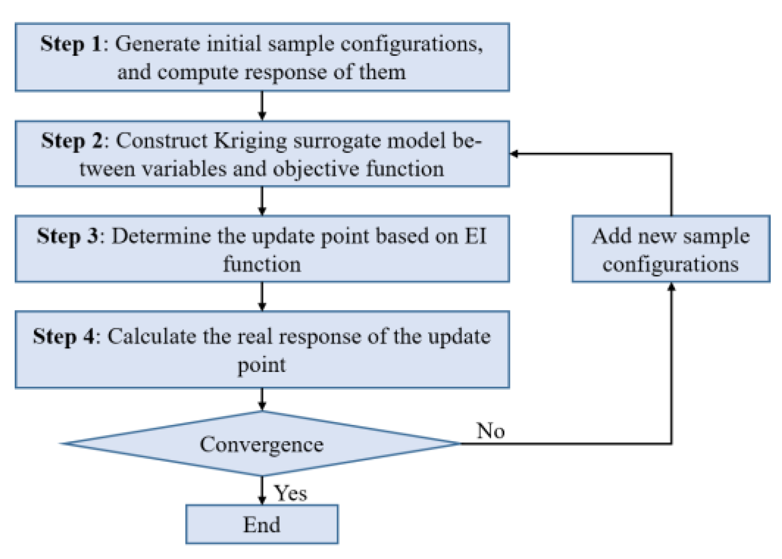
The calculation cost of the EI function is much lower than the actual response calculation cost. Intelligent algorithms such as Genetic Algorithm and Simulated Annealing Algorithm can be used to obtain the maximum expected value of EI, and the point where EI function reaches the maximum value is taken as the update point [35]. The optimization framework of EGO is shown in Figure 2, and the steps are as follows.
Step 1: The initial sample configurations set is generated, the corresponding responses are calculated, and the sample database is initialized.
Step 2: The Kriging surrogate model is constructed between design variables and objective function.
Step 3: Taking the value of EI function as the objective function, the point that maximizes it is selected as the update point.
Step 4: The real finite element model is used to calculate the response of the updated points, and the updated points and responses are put into the sample library to update the surrogate model.
Step 5: The above steps 2–4 are repeated and iterated until convergence conditions are satisfied, and then the optimization results are outputted.

4.2. An Optimization Framework for Vibration Reduction of Complex Thin-Walled Shells Accelerated by the Global POD ROM

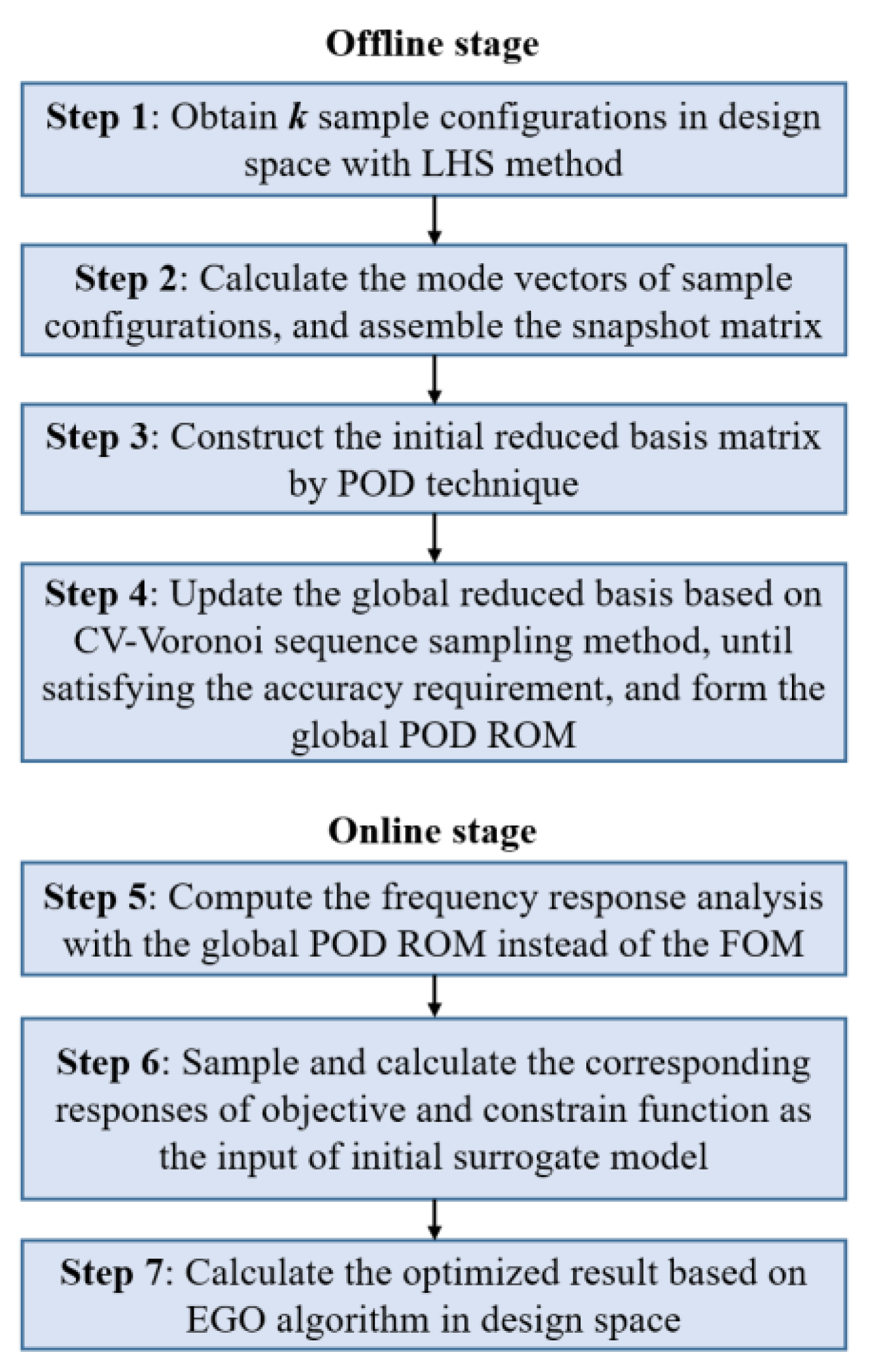
The process of vibration reduction optimization based on the global POD ROM is shown in Figure 3, which is divided into offline stage and online stage. The offline stage is the preparation stage, which is used to build and update the global POD ROM, and the online stage is the application stage, which uses the built global POD ROM for vibration reduction optimization design. The steps are as follows:
Step 1: In offline stage, the initial configurations are obtained by sampling in the design space using LHS.
Step 2: The mode shapes corresponding to the initial configurations are calculated and the snapshot matrix is assembled.
Step 3: The correlation matrix is calculated according to the snapshot matrix, and the initial reduced basis matrix is obtained by POD technique.
Step 4: Based on the CV–Voronoi sequence sampling technique, the sample configurations are increased, and the corresponding mode shapes are obtained to update the global POD reduced basis matrix until the ROM meets the accuracy requirement.
Step 5: In the online stage, the global POD ROM is used to replace the FOM and the frequency response analysis is computed.
Step 6: Sampling is done within the design space, and the corresponding response of optimization objective function and constraints calculated, which is used as the input to construct the initial surrogate model.
Step 7: Based on the EGO algorithm, the design in the design space is optimized, and the optimization result parameters outputted.

5. Illustrative Examples

5.1. Vibration Reduction Optimization Design of S-Shaped Curved Stiffened Shell

As a typical complex thin-walled structure in the aviation field, the S-shaped curved stiffened shell is widely used in fighter planes due to its advantages of infrared stealth and low exploration [36]. With extremely complex service conditions, the dynamic response of the S-shaped curved stiffened shell is very significant, as it is prone to large deformation and vibration, affecting its working stability and even leading to structural failure and destruction. Therefore, it is important to perform the vibration reduction optimization to ensure the strength and safety of the S-shaped curved stiffened shell under service conditions. However, due to the complexity of the structure, the degrees of freedom of mesh model of the S-shaped curved stiffened shell are large, which would affect the efficiency of frequency response analysis and prolong the design period of the structure. In this section, the structure is optimized using the proposed vibration reduction optimization framework based on the global POD ROM.
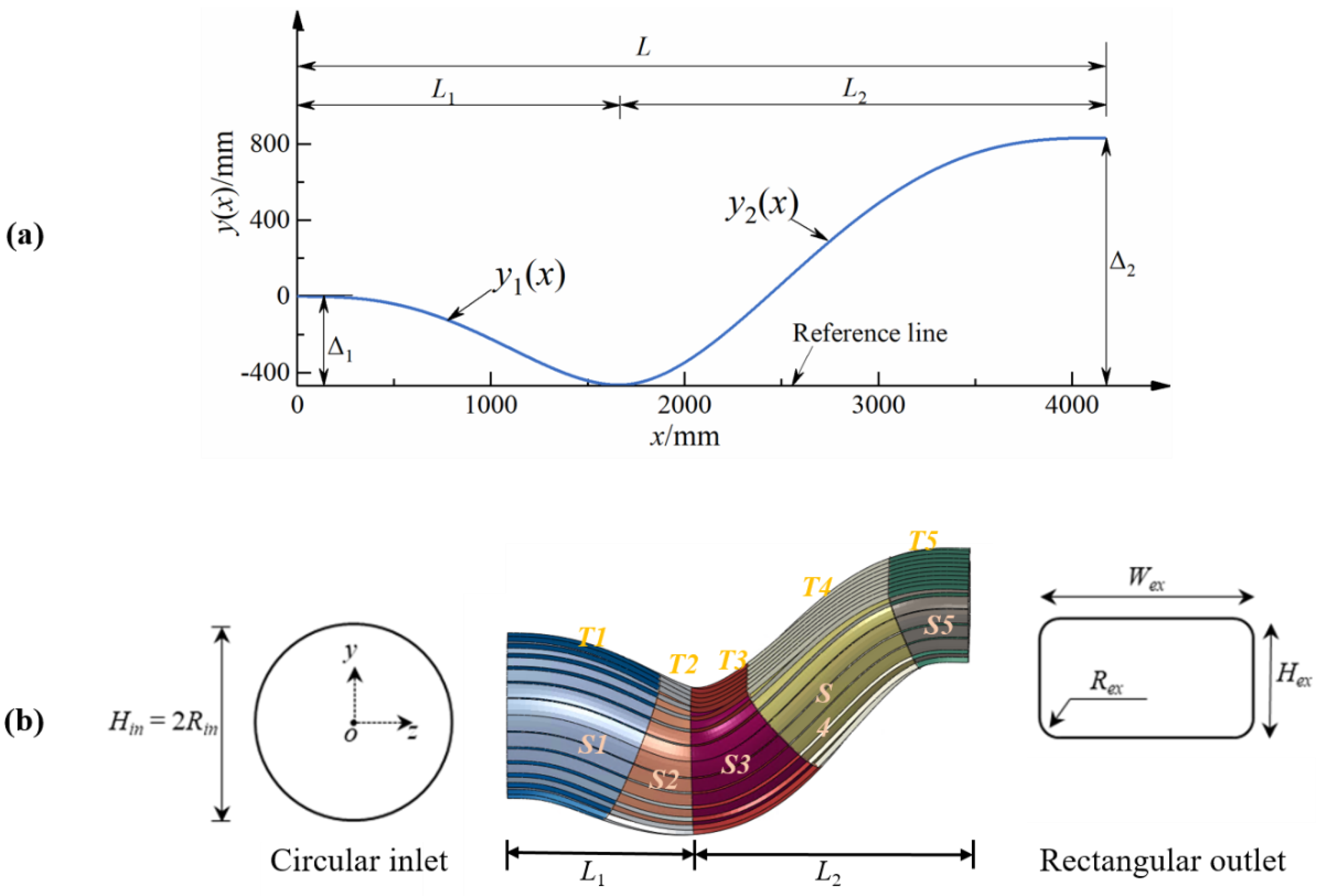
The inner profile of the S-shaped curved stiffened shell is composed of a center line and a series of sections varying along the center line. The section at the inlet is circular and at the outlet is fillet rectangular, as shown in Figure 4. Equations (24) and (25) give the expression of the center line, where Δ 1 and Δ 2 , respectively, represent the vertical distance from the center of the left circular section and the right rectangular section to the horizontal reference line. L is the length of the horizontal reference line, L1 and L2 are the horizontal reference line lengths of the first and second center line expressions, respectively.
y 1 ( x ) Δ 1 = 3 ( x L 1 ) 4 4 ( x L 1 ) 3 ,   0 x L 1 ,
y 2 ( x ) Δ 2 = 3 ( x L 1 L 2 ) 4 8 ( x L 1 L 2 ) + 6 ( x L 1 L 2 ) 2 Δ 1 Δ 2 ,   L 1 x L .
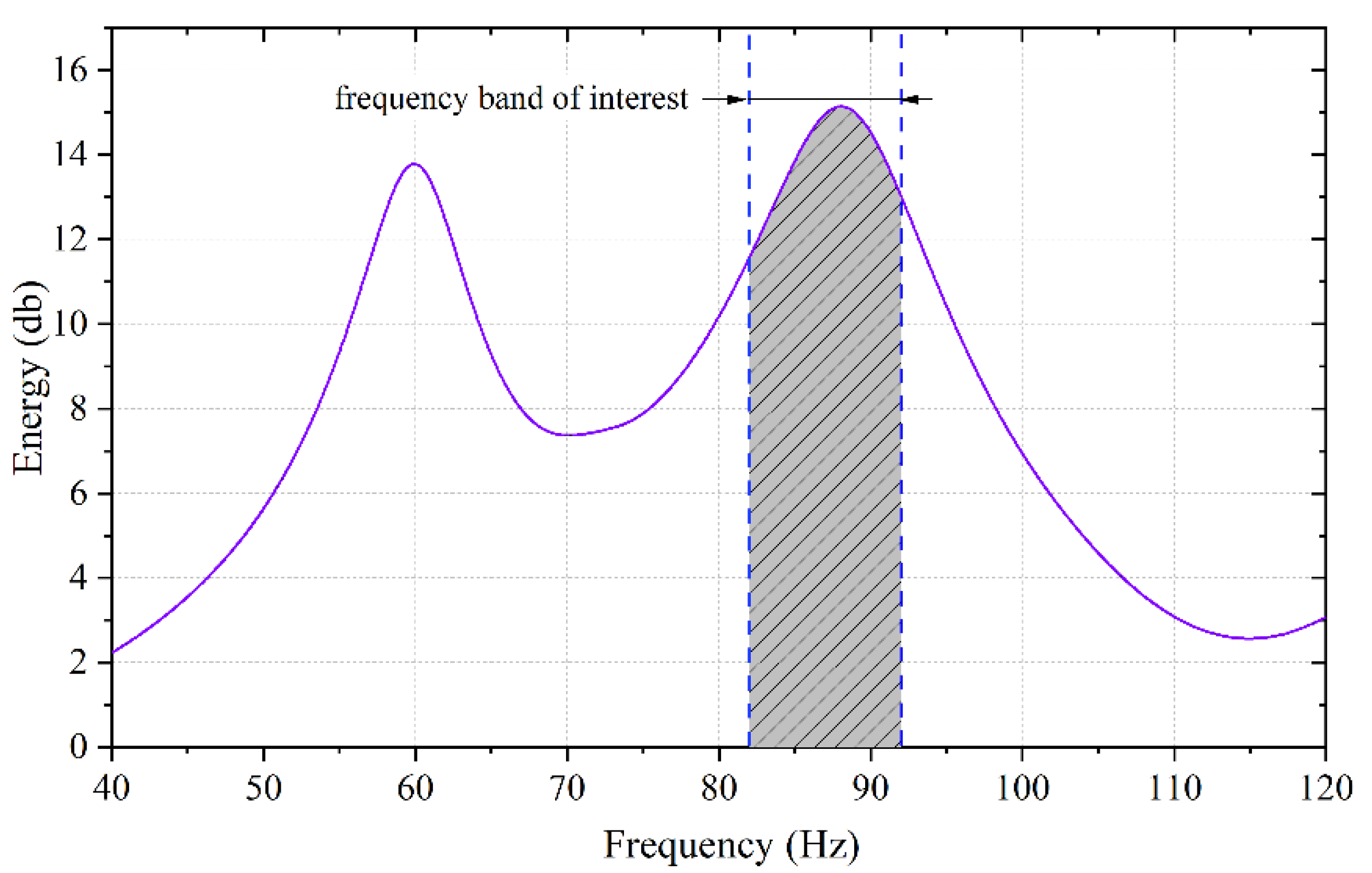
The geometric dimensions of the structure are as follows: L = 4170   mm , L 1 / L 2 = 0.66 , Δ 1 / L 1 = 0.28 , Δ 2 / L 2 = 0.516 . The width and height of the fillet rectangular section on the right are W e x = 1500   mm and H e x = 620   mm , respectively, and the fillet radius is R e x = 130   mm . The radius of the circular section on the left is R i n = 700   mm . The number of ring stiffeners and axial stiffeners, respectively, are 30 and 6. The height of the stiffeners is 50 mm. The thickness of skin and stiffeners of the initial configuration are 3 mm. Material properties are as follows: Young’s modulus E = 167   GPa , Poisson’s ratio μ = 0.3 , and density ρ = 7800   kg / m 3 . The Rayleigh damping coefficient is obtained according to the previous data and set as α = 25 , β = 1.25 × 10 4 . The finite element model is discretized by S4 element, with 13,470 nodes, 13,680 elements and 80,820 degrees of freedom. The boundary conditions are that the inlet section is clamped, and the degrees of freedom of the outlet section is only relaxed along x direction. A harmonic load with 1 N amplitude is applied to all nodes in the x direction of the outlet section on the right. The analysis frequency range is [40 Hz, 120 Hz], and the frequency sweep interval is 0.1 Hz. Using the FOM, the energy–frequency curve is calculated as shown in Figure 5; the calculation takes 3752.8 s. As shown in Figure 5. Energy–frequency response of initial configuration calculated by the FOM of the S-shaped curved stiffened shell., the first resonant frequency is 60.1 Hz, and the second one is 88.0 Hz. The frequency range of interest is [88.0 Hz, 92 Hz], the energy sum of which is 1409.2 db (shown in Figure 5, shadow area).
The design variables for vibration reduction optimization of the S-shaped curved stiffened shell include a total of 11 parameters, including the thickness of five sections of skin ( S 1 , S 2 , S 3 , S 4 , S 5 ), the thickness of five sections of axial stiffeners ( T 1 , T 2 , T 3 , T 4 , T 5 ), and the thickness of ring stiffeners ( T a ). The optimization objective is to minimize the energy in the interest frequency range. The constraints are that the optimized configuration mass is not higher than the initial configuration mass, and the optimized first resonance frequency is not less than the initial value. The optimization formulation is:
min :   T e = ω a ω b E ¯ ( ω ) s . t . :   x i l b x x i u p , i = 1 , , I M a s s ( x ) M a s s 0 f r e q ( x ) f r e q 0  
where x is the vector of design variables, and x i l b and x i u b are the lower and upper bound of the design variables, respectively. M a s s ( x ) represents the mass of the structure, and M a s s 0 is the mass of the initial configuration (657.92 kg). The term f r e q ( x ) is the first resonance frequency; f r e q 0 is the first resonance frequency of the initial configuration (60.1 Hz). Te is the energy sum of the interest frequency range [ ω a , ω b ].
Five sample configurations are sampled in [1.5 mm, 4.5 mm] as the initial sample configurations, and the initial reduced basis matrix is obtained to reduce the order of the stiffness matrix, damping matrix and mass matrix to construct the initial ROM. In order to verify the prediction accuracy of the initial reduced basis matrix in the entire design space, the LHS is used to obtain 20 sample configurations, and the energy–frequency curves are obtained based on the FOM and the ROM respectively, and then RMSEs are calculated. As shown in Figure 6a, the maximum RMSE is 1.082, and the corresponding results of the ROM and the FOM of the No.1 sample configuration are shown in Figure 6b. The curve deviation of the two is obvious, indicating that the accuracy based on the initial reduced basis is insufficient, and the reduced basis matrix needs to be updated to improve the global accuracy of the ROM.
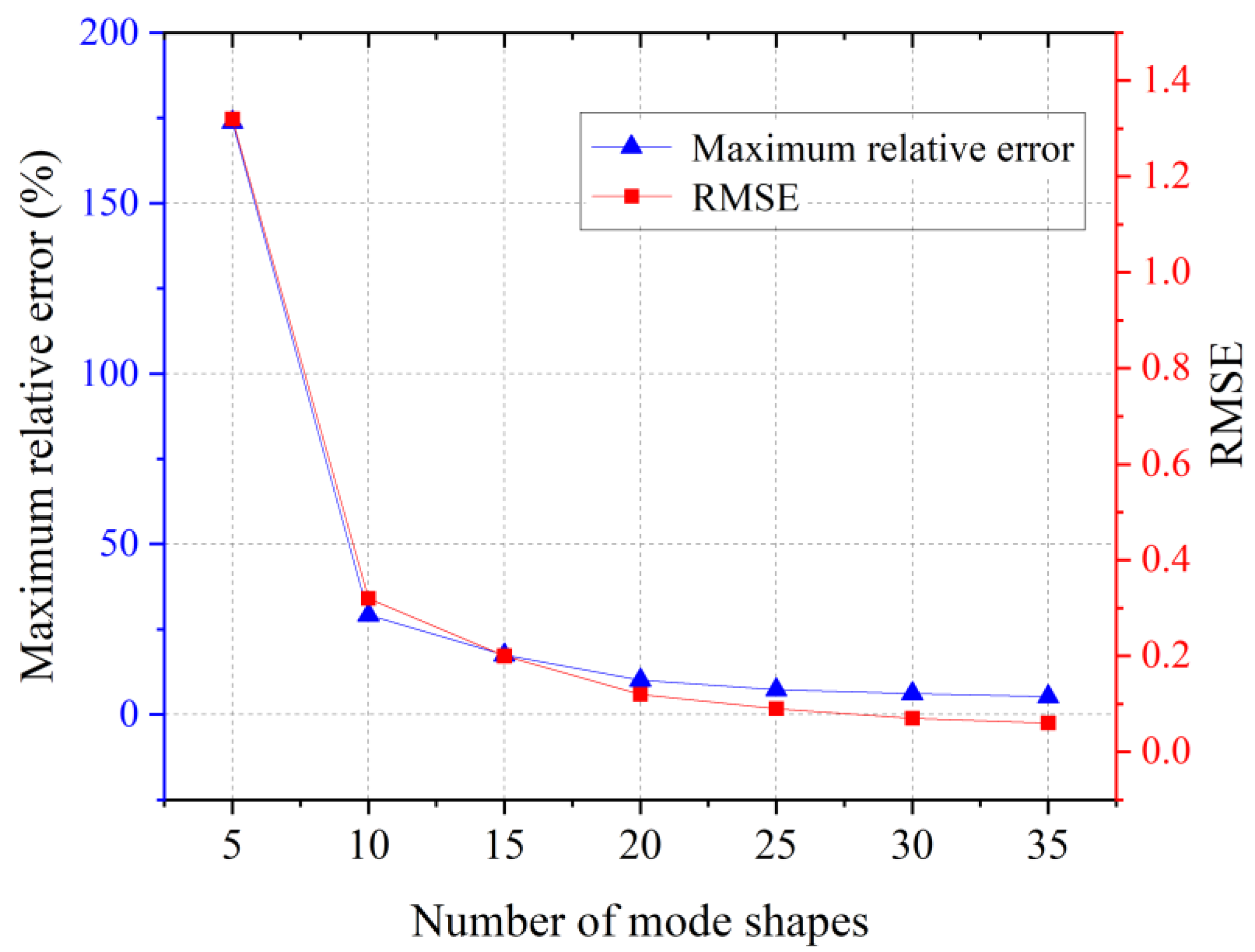
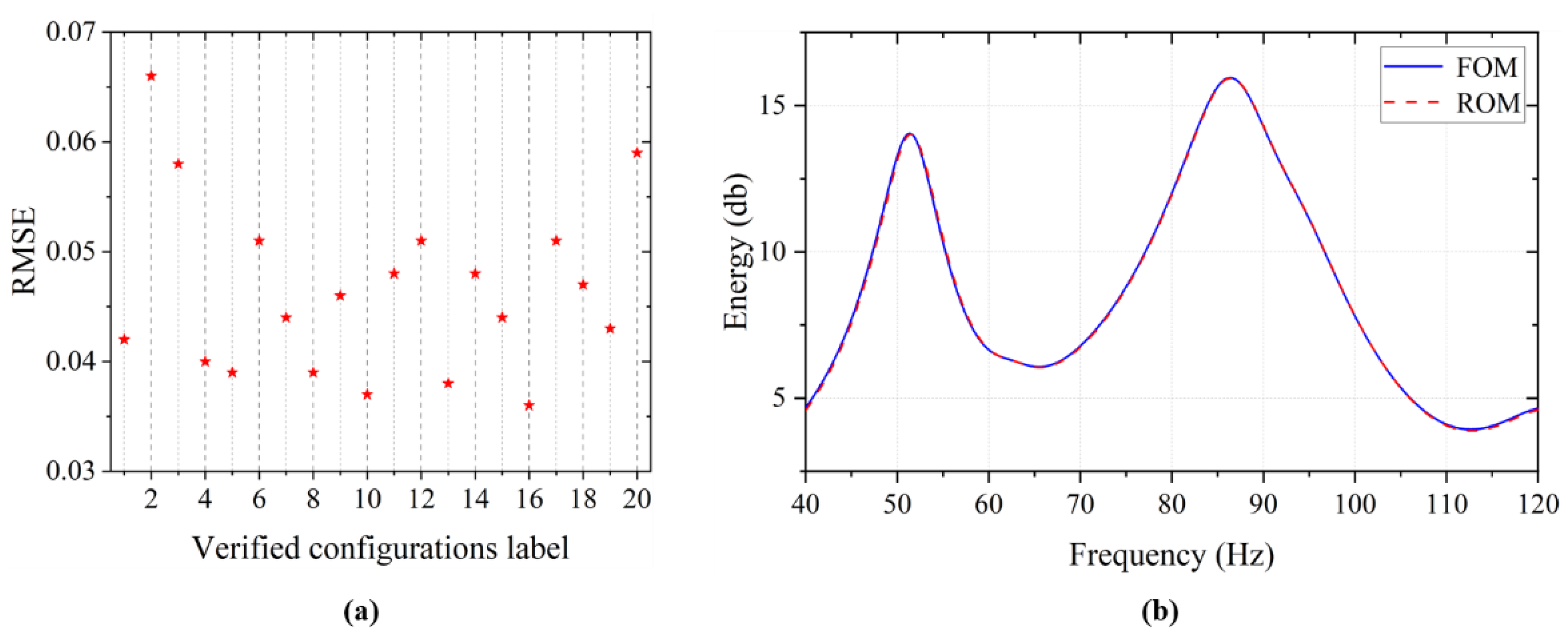
The CV–Voronoi sequence sampling method is used to increase the sample configurations to realize the adaptively global POD ROM update. An inappropriate truncation threshold increases offline time under the premise of limited improvement in the global POD ROM accuracy. To confirm the truncation threshold for the global POD ROM update, a simple test is done. For a certain sample configuration, the first 5, 10, 15, 20, 25, 30, and 35 mode shapes are used, respectively, to construct the ROM by the POD method. The ROM has a higher accuracy only for the confirmed sample configuration, and its global accuracy is low. For the FOM and each of the ROMs distinguished by the number of mode shapes, the maximum relative error in the frequency response energy at the frequency point and the RMSE value of the energy–frequency curves are calculated, as shown in Figure 7. When the number of mode shapes for ROM is 25, the RMSE value is 0.09, and the maximum energy relative error is 7.3%. With the increase in the number of mode shapes, the accuracy gains of the ROM decrease. The global POD ROM has the same rule. If the truncation threshold is less than 0.1, more time will be spent, and the accuracy improvement will be limited. At the same time, when the maximum energy relative error is 7.3%, the relative error of the objective frequency band energy sum is 0.09%. Considering the calculation time and accuracy, when the maximum RMSE of the energy–frequency curves of the FOM and the ROM is less than 0.10, the ROM has a relatively high precision. The convergence condition is satisfied after the continuous increase of 18 sample configurations. A global POD ROM is constructed based on 23 sample configurations. The 20 sample configurations mentioned above are used to check the accuracy of the updated ROM. The RMSE is shown in Figure 8a. The RMSE corresponding to all verified configurations is less than 0.10, and the maximum value is 0.066, which corresponds to the second sample configuration. The results based on the ROM and the FOM are shown in Figure 8b, and the curves of the two are almost completely coincidental. Compared with the accuracy of the initial ROM, the accuracy based on the updated global POD ROM is greatly improved. This shows that the updated ROM has higher prediction accuracy in the design space. The average single computation time based on the global POD ROM is 115.2 s, which is 96.9% less than the average single computation time of the FOM (3752.8 s), indicating that the proposed approach can significantly improve the computational efficiency of frequency response analysis.
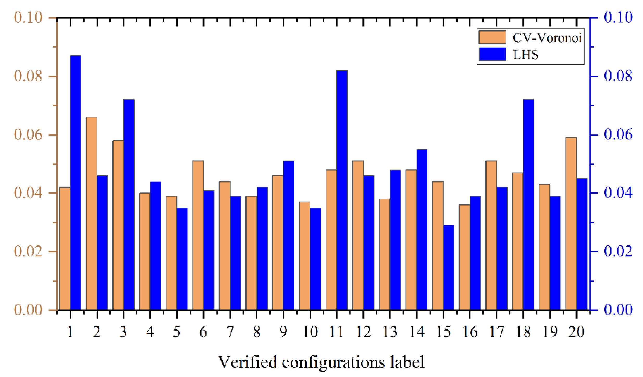
To verify the advantages of the CV–Voronoi sequence sampling method in adaptively updating the global POD ROM, LHS is used to directly sample 23 configurations to construct a global POD ROM. Then, the same 20 sample configurations are used to verify the accuracy of the ROM constructed by LHS. The obtained RMSE is compared with that of the ROM constructed adaptively by CV–Voronoi sequence sampling, as shown in Figure 9. The RMSE with CV–Voronoi sequence sampling method is generally low. The RMSE with LHS method is significantly lower at the 1, 11, and 18 validation configurations. It should be noted that the above comparison is based on the premise that the number of LHS is known. But in engineering practice, it is difficult to directly determine the appropriate sampling number without prior experience. This further reflects the advantages of CV–Voronoi sequence sampling method in constructing the global POD ROM.
Then, the modal superposition method and the modal acceleration method are used, respectively, for frequency response analyses of the initial configuration in comparison to the global POD ROM. The first 100 mode shapes are selected. The results in Table 1 show that the global POD ROM has higher efficiency and accuracy. It should be noted that when the structure has multiple components or different materials, the damping matrix does not satisfy the mode shape orthogonalization, and the frequency response analysis cannot reduce the order through the mode shape space. The global POD ROM has more potential in the order reduction calculation of complex structures because it does not consider the structure of the actual physical model.
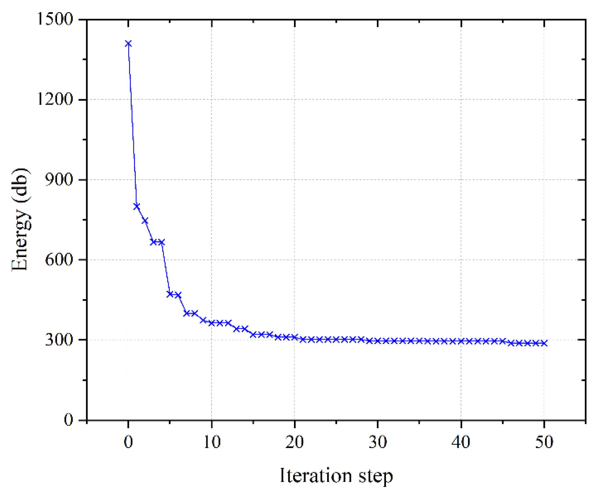
Furthermore, the global POD ROM is used instead of the FOM for the vibration reduction optimization design of the S-shaped curved stiffened shell. In the optimization design stage, 50 sample configurations are selected to calculate the corresponding responses to construct the initial Kriging surrogate model. The upper limit of iteration is 300. The iteration stops when the maximum number of iteration steps is reached or Formula (27) is satisfied,
max E ( I ( x ) ) T e max T e min ε ,
where the truncation threshold ε = 1 × 10 4 , then the optimization design is carried out based on EGO. The iterative convergence curve is shown in Figure 10. After the 20th iteration step, the energy of the objective frequency band is only reduced by about 1% compared with the initial value, but the calculation time is about 3400 s, during which the FOM cannot complete a frequency response analysis. This means that in the online stage, the calculation time of frequency response analysis is greatly reduced, and more strict convergence conditions or more iteration steps can be given to obtain relatively better results.
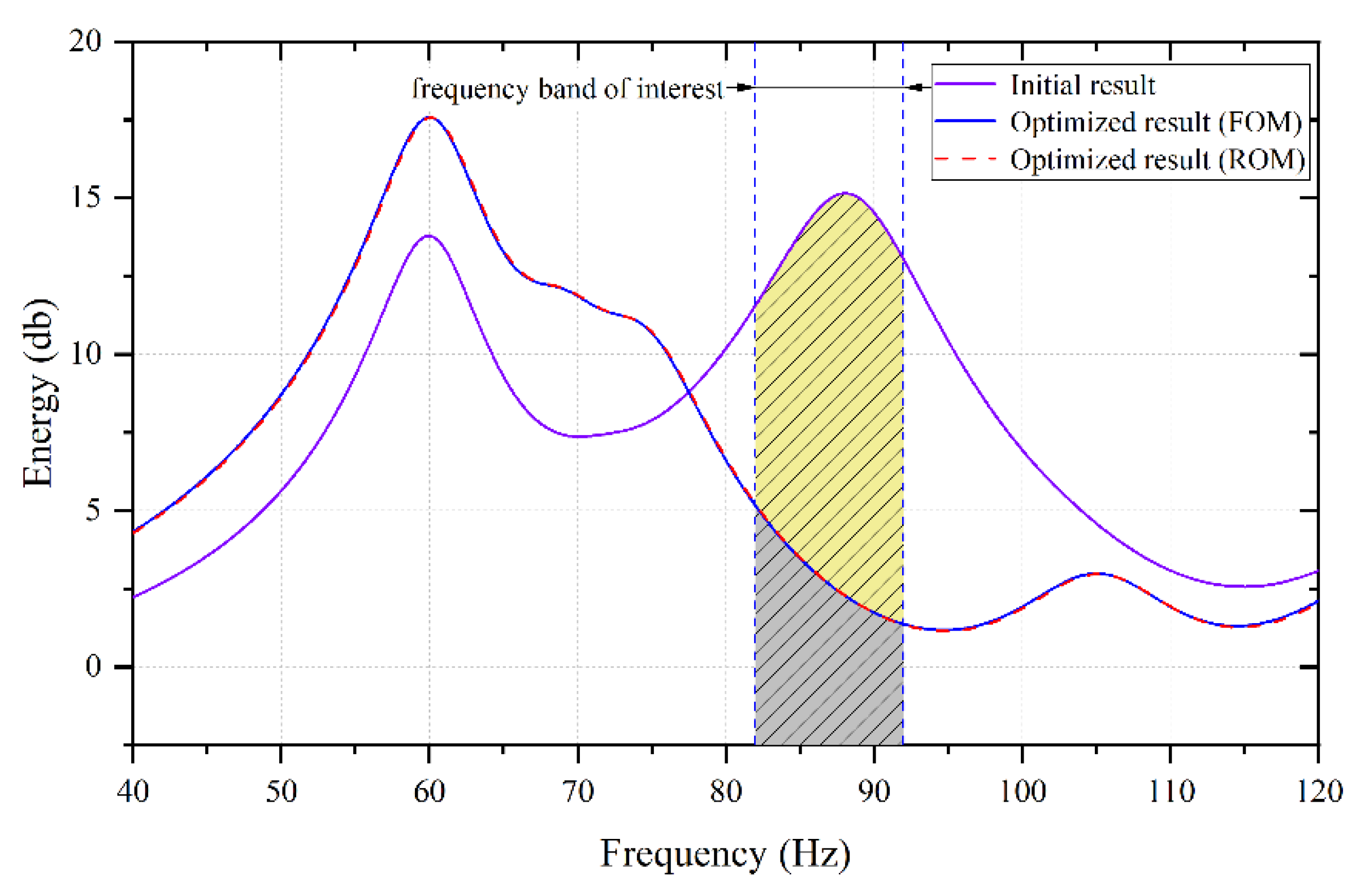
The optimized results are shown in Table 2. The optimized configuration can ensure that the first resonant frequency and mass satisfy the constraints, while the energy sum of the interest frequency range decreases significantly. The optimized energy sum of the interest frequency range is 287.0 db, which is 79.6% lower than the initial value (1409.2 db). The optimized configuration has no resonance frequency in the [82 Hz, 92 Hz], and the energy–frequency curve has no peak value in this frequency range, which is also the main reason why the energy sum of interest decreases significantly. Figure 11 shows the energy–frequency curves before and after the vibration reduction optimization of the S-shaped curved stiffened shell. The energy–frequency curve of the optimized configuration is calculated based on the global POD ROM and the FOM, which almost completely coincide with each other. The Te is 288.3 db and 287.0 db, respectively, and the relative error is only 0.5%. The accuracy and credibility of the optimized analysis results based on the global POD ROM are fully verified.
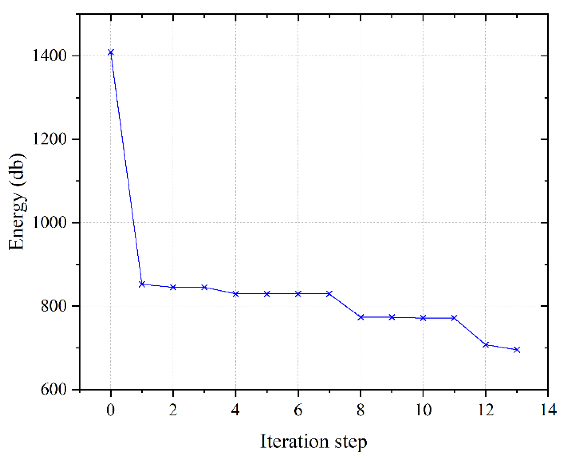
Next, the optimization ability of the global POD ROM is discussed. In offline stage, it takes 31.7 h to construct the global POD ROM. In the online stage, the vibration reduction optimization based on the global POD ROM uses 50 initial sample configurations to construct the initial surrogate model. The optimization iteration is 50 steps, and the time is 3.2 h, so the total time is 34.9 h. However, with the same time-consuming condition, the FOM can only finish 33 frequency response analyses, and it is difficult to complete the initial sampling if the same 50 initial samples are used. For comparison, 20 sample configurations are used to construct the initial surrogate model, and 13 steps of optimization iteration are performed. The convergence curve is shown in Figure 12, and the optimization results are shown in Table 2. It should be noted that the prerequisite for the above comparison is that the overall optimization time is the same, so the optimization iteration curve of the FOM does not converge, precisely due to the time constraint. This is also the significance of the above comparison. By comparison, the vibration reduction optimization result based on the global POD ROM are reduced by 58.8% compared with that directly using the FOM, which verifies that the proposed approach has better optimization ability.

5.2. Vibration Reduction Optimization Design of PAF

Satellites are subjected to a variety of vibration loads, among which the most severe vibration environment is in the launch process, including rocket engine pulse, transient impact load generated by rocket separation, explosive impact, and transverse aerodynamic load [37]. The load is directly transmitted from the satellite and rocket interface to the satellite, and then acts on the sub-stages and instruments of the satellite system, often leading to the exceeding of the satellite’s dynamic environment, affecting the life of the satellite, and putting forward more stringent design indexes for the instruments carried on the satellite. As an important part connecting the satellite to the rocket, the PAF plays the role of load transmission, so it is necessary to carry out vibration reduction optimization design to improve the dynamic environment of the satellite during launch. Also, due to the complexity of the structure, the frequency response analysis is inefficient, and the optimization design circle is too long to satisfy the engineering. To solve above problems, in this section, the PAF is optimized using the proposed vibration reduction optimization framework based on the global POD ROM.
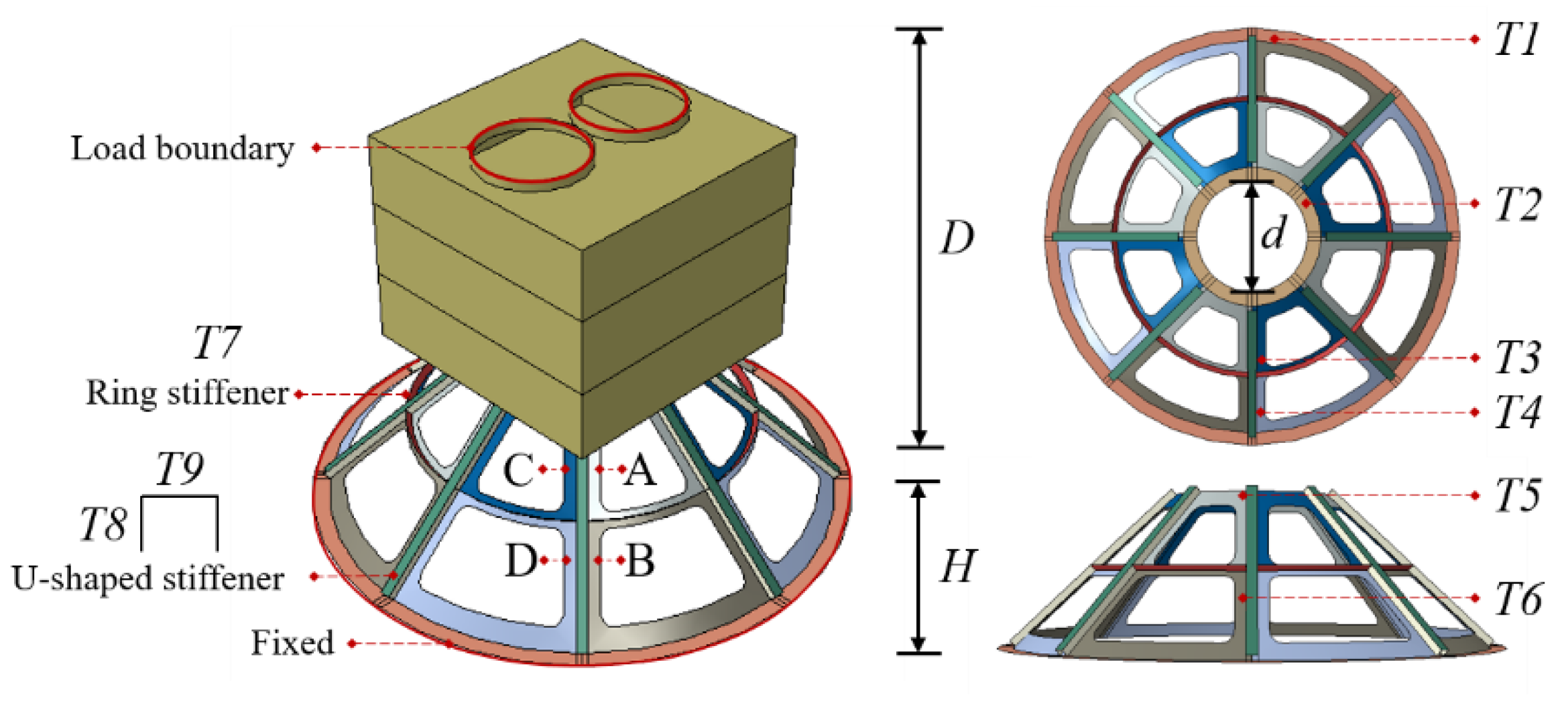
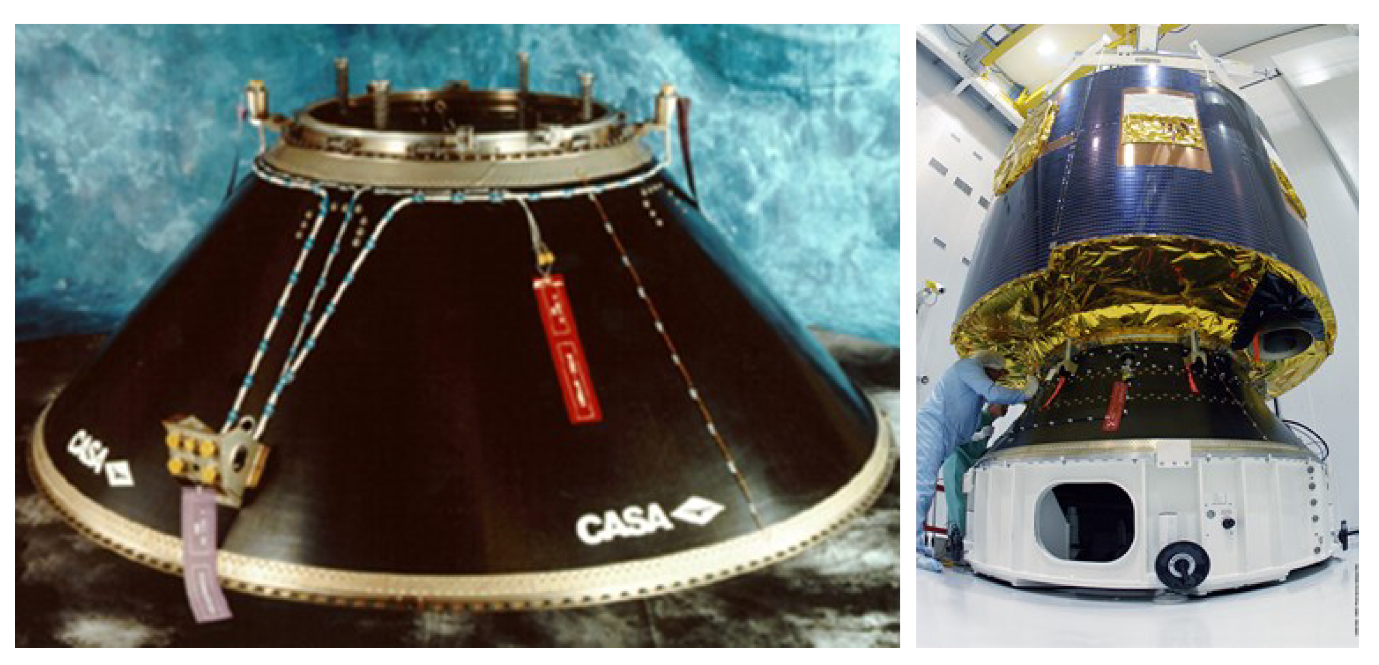
As shown in Figure 13, the PAF structure in the engineering is thin-walled stiffened structure. The numerical model of the PAF structure is constructed according to the actual structure, and the simplified satellite structure is connected at top, as shown in Figure 14. D and d are the diameters of the lower and upper end frames, respectively. H is the height of the PAF structure.
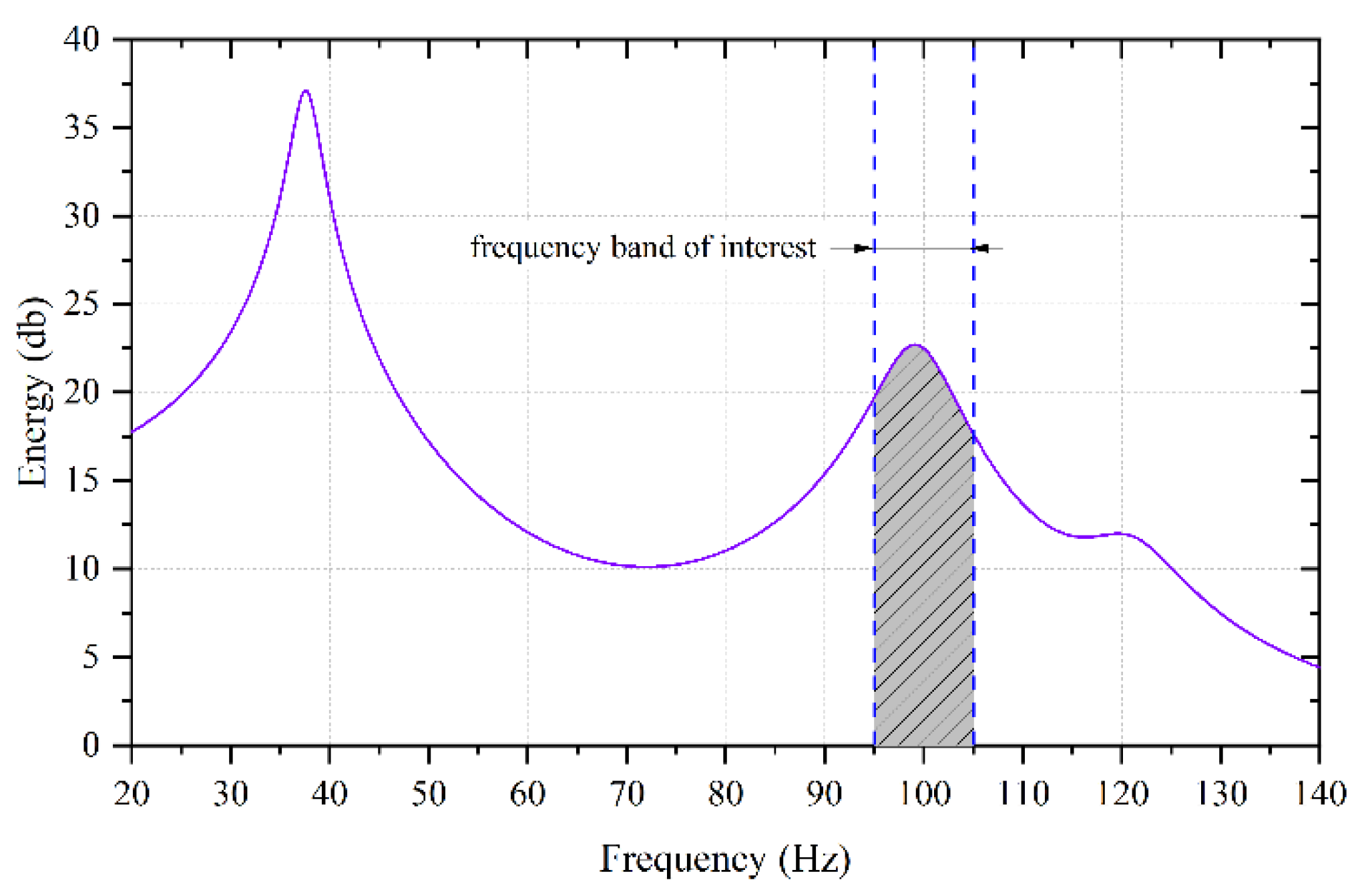
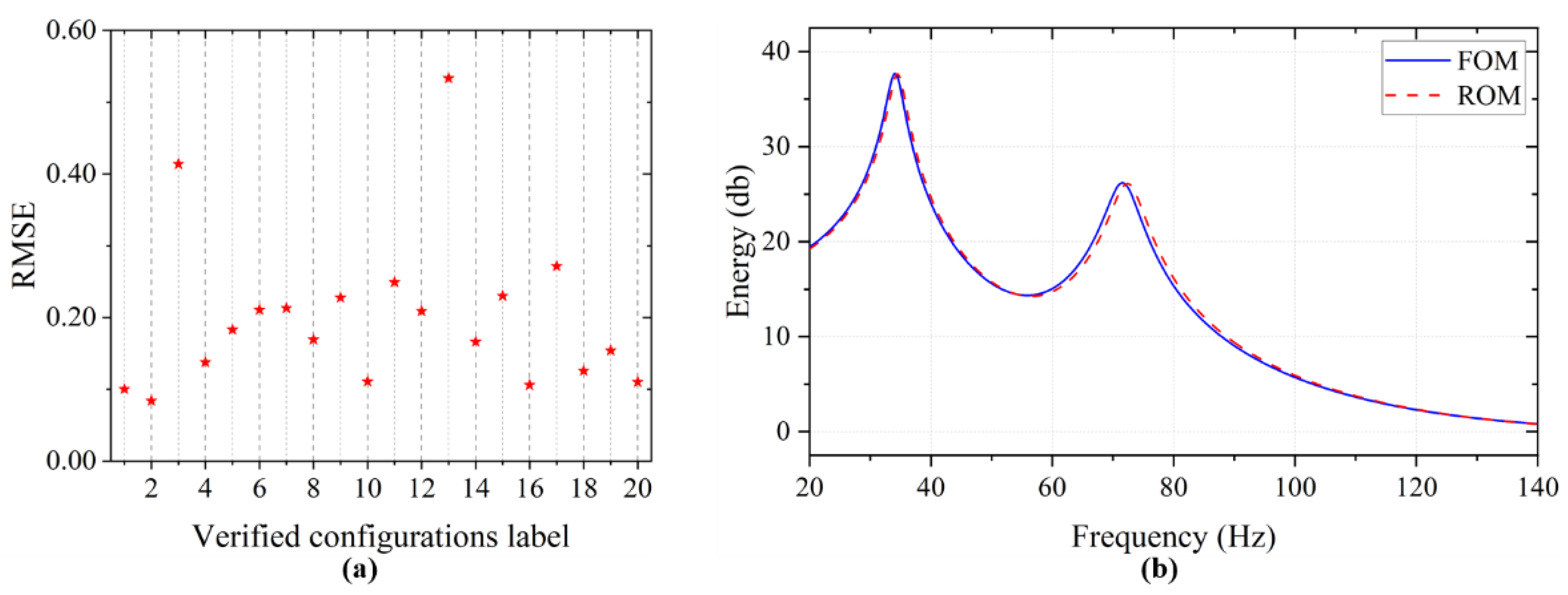
The geometric sizes of the PAF structure are as follows: D = 100 0   mm , d = 2 40   mm , and H = 300   mm . The number of U-shaped stiffeners is eight, and the flange and web are 20 mm and 15 mm, respectively. The number of ring stiffeners is one, the height of the stiffener is 15 mm. The thickness of all skin and stiffeners in the initial configuration of the structure is 3 mm. The shell thickness of the simplified satellite structure is 15 mm and the size is 500 × 500 × 400 mm. The satellite is separated by square thin shells at 130 mm and 270 mm relative to the height of itself. The hole is symmetrical at the top of satellite, the diameter is 205 mm, the distance of the center of the two circles is 225 mm, and the circular interface is 20 mm high. The material properties are as follows: Young’s modulus E = 7 0   GPa , Poisson’s ratio μ = 0.3 , density ρ = 27 00   kg / m 3 , and the Rayleigh damping coefficient of the whole structure is obtained according to the previous data and set as α = 1 2.5 , β = 1 × 10 4 . The finite element model is discretized by S4 and S3 elements, with 19,282 nodes, 18,928 elements and 115,692 degrees of freedom. The edge of the lower end frame is fixed, and the harmonic load of amplitude 1 N is applied to all nodes in the x, y and z directions of the two circular interface boundaries at the top of the satellite. The analysis frequency range is [20 Hz, 140 Hz], and the frequency sweep interval is 0.1 Hz. The FOM is used to calculate the energy-frequency curve, as shown in Figure 15, which takes 5849.6 s. As can be seen from Figure 15, the first resonance frequency of the structure is 37.6 Hz, the second resonance frequency is 99.3 Hz, and the energy sum in the frequency range of interest [95.0 Hz, 115.0 Hz] is 2117.8 db (shaded area in Figure 15).
The design variables for vibration reduction optimization of the PAF structure are, respectively, the thickness of 9 regions ( T 1 , T 2 , T 3 , T 4 , T 5 , T 6 , T 7 , T 8 , T 9 ) of the lower end frame, upper end frame, skin area A, skin area B, skin area C, skin area D, U-shaped stiffener web and flange, and ring stiffener). The optimization formulation is consistent with that of (26) in Section 5.1. The initial mass of the PAF is 5.64 kg (without satellite), and the initial first resonance frequency is 37.6 Hz.
Five sample configurations are sampled in the design space [1.5 mm, 4.5 mm] as the initial sample configuration set to form the initial ROM. In order to verify the prediction accuracy of the initial ROM in the whole design space, 20 sample configurations are sampled by LHS, and the energy–frequency curves are obtained based on the FOM and the ROM respectively, and the RMSE of the two are computed. As shown in Figure 16a, the maximum RMSE is 0.533, and the corresponding results of the ROM and the FOM of the No.13 sample configuration are shown in Figure 16b. The curve deviation of the two is obvious, indicating that the accuracy of the initial ROM is insufficient, and the reduced basis matrix needs to be updated to improve the global accuracy of the ROM.
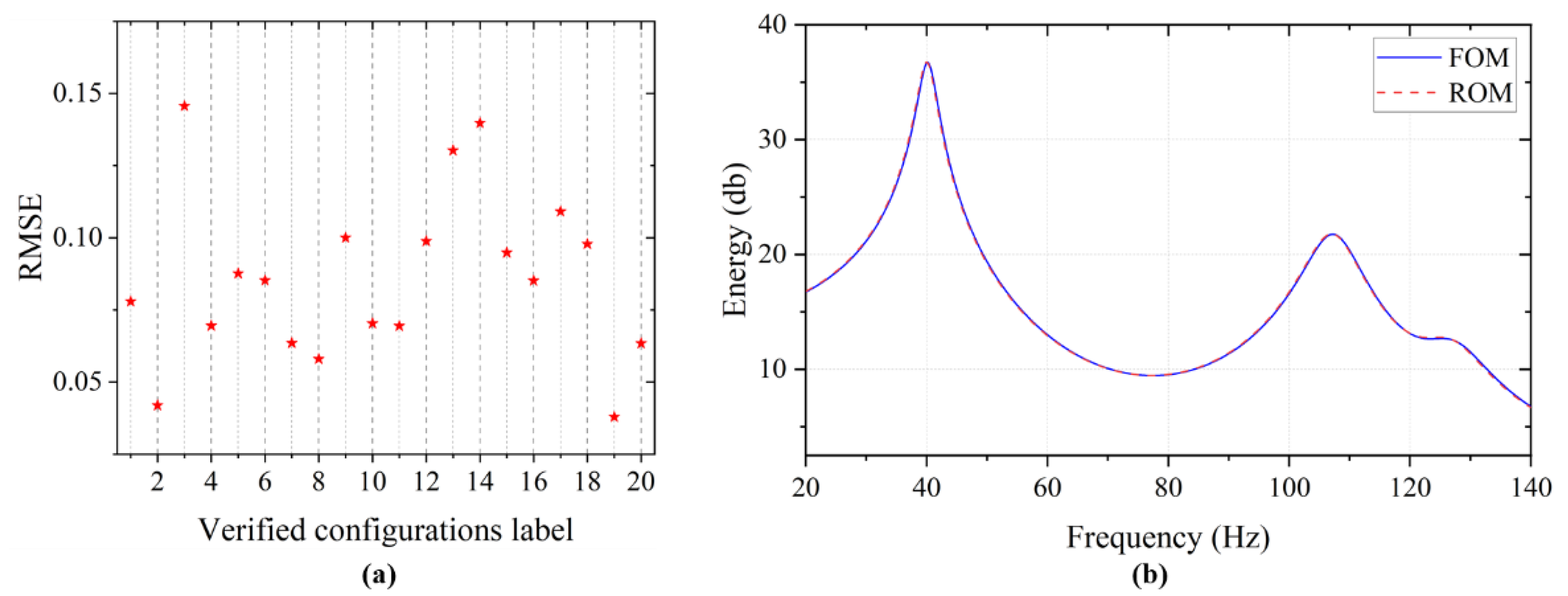
The CV–Voronoi sequence sampling method is used to increase the sample configurations to realize the adaptive global POD ROM update. According to the same test in Section 5.1, for this problem, when the maximum RMSE of energy–frequency curves of the FOM and the ROM is less than 0.15, the ROM has a relatively high precision. Therefore, the RMSE truncation threshold is set as 0.15 in this example. The convergence condition is satisfied after the continuous increase of 10 sample configurations. A global POD ROM is constructed based on 15 sample configurations. The 20 sample configurations mentioned above are used to check the accuracy of the updated ROM. The RMSE is shown in Figure 17a. The RMSE corresponding to all verified configurations is less than 0.15, and the maximum value is 0.146, which corresponds to the No. 3 sample configuration. The results based on the ROM and the FOM are shown in Figure 17b, and the curves of the two are almost completely coincidental. Compared with the accuracy of the initial ROM, the accuracy based on the updated global POD ROM is greatly improved. This shows that the updated ROM has higher prediction accuracy in the design space. The average single computation time based on the global POD ROM is 138.6 s, which is 97.6% less than the average single computation time of the FOM (5849.6 s), indicating that the proposed approach can significantly improve the computational efficiency of frequency response analysis.
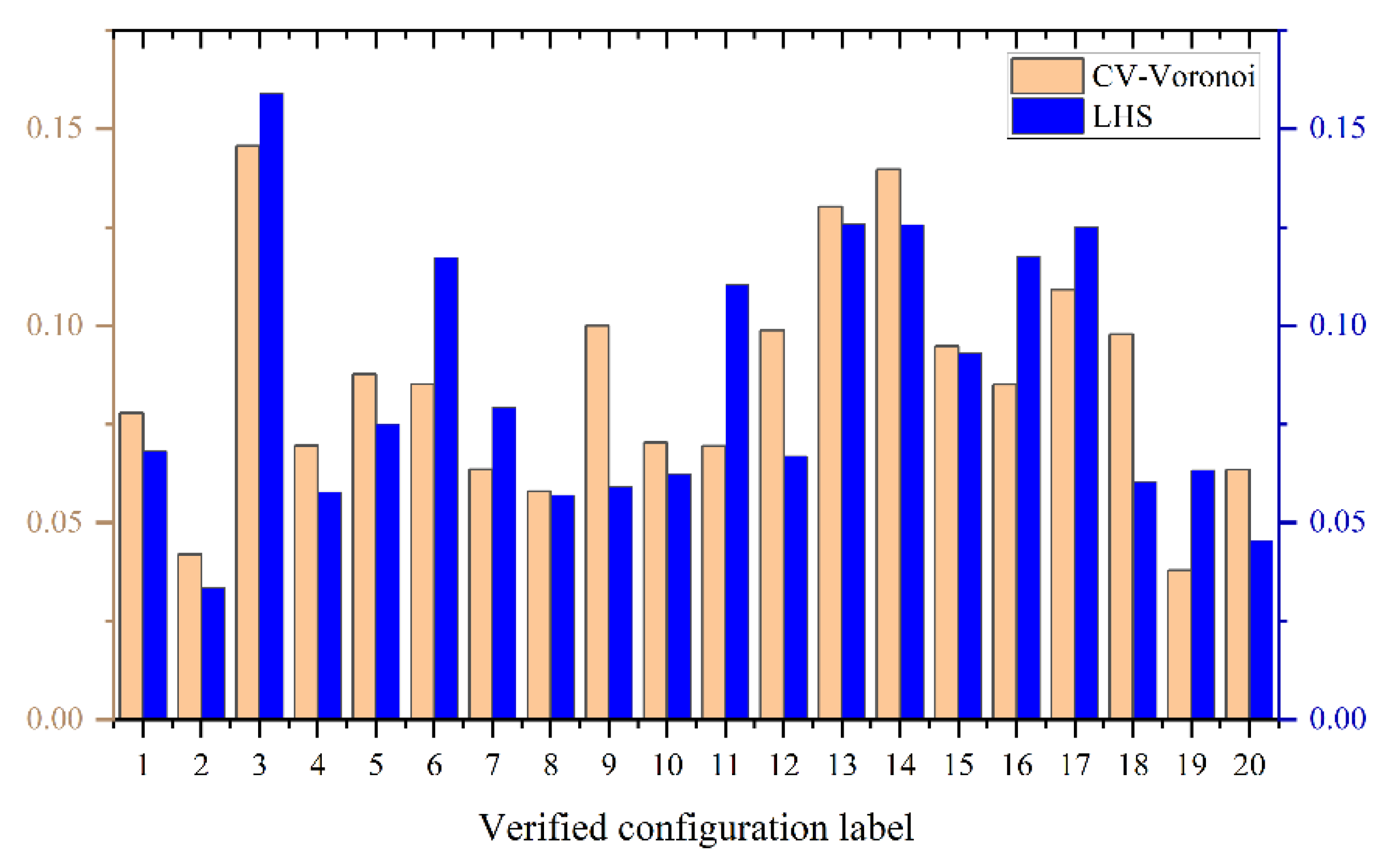
To verify the advantages of the CV–Voronoi sequence sampling method to adaptively update the global POD ROM, LHS is used to directly sample 15 configurations to construct a global POD ROM. Then, the same 20 sample configurations are used to verify the accuracy of the ROM constructed by LHS. The obtained RMSE is compared with that of the ROM constructed adaptively by CV–Voronoi sequence sampling, as shown in Figure 18. The RMSE with the CV–Voronoi sequence sampling method is generally low. The RMSE with LHS method is significantly lower at the 3, 6, 11, 16 and 17 validation configurations. This reflects the advantages of the CV–Voronoi sequence sampling method in constructing the global POD ROM.
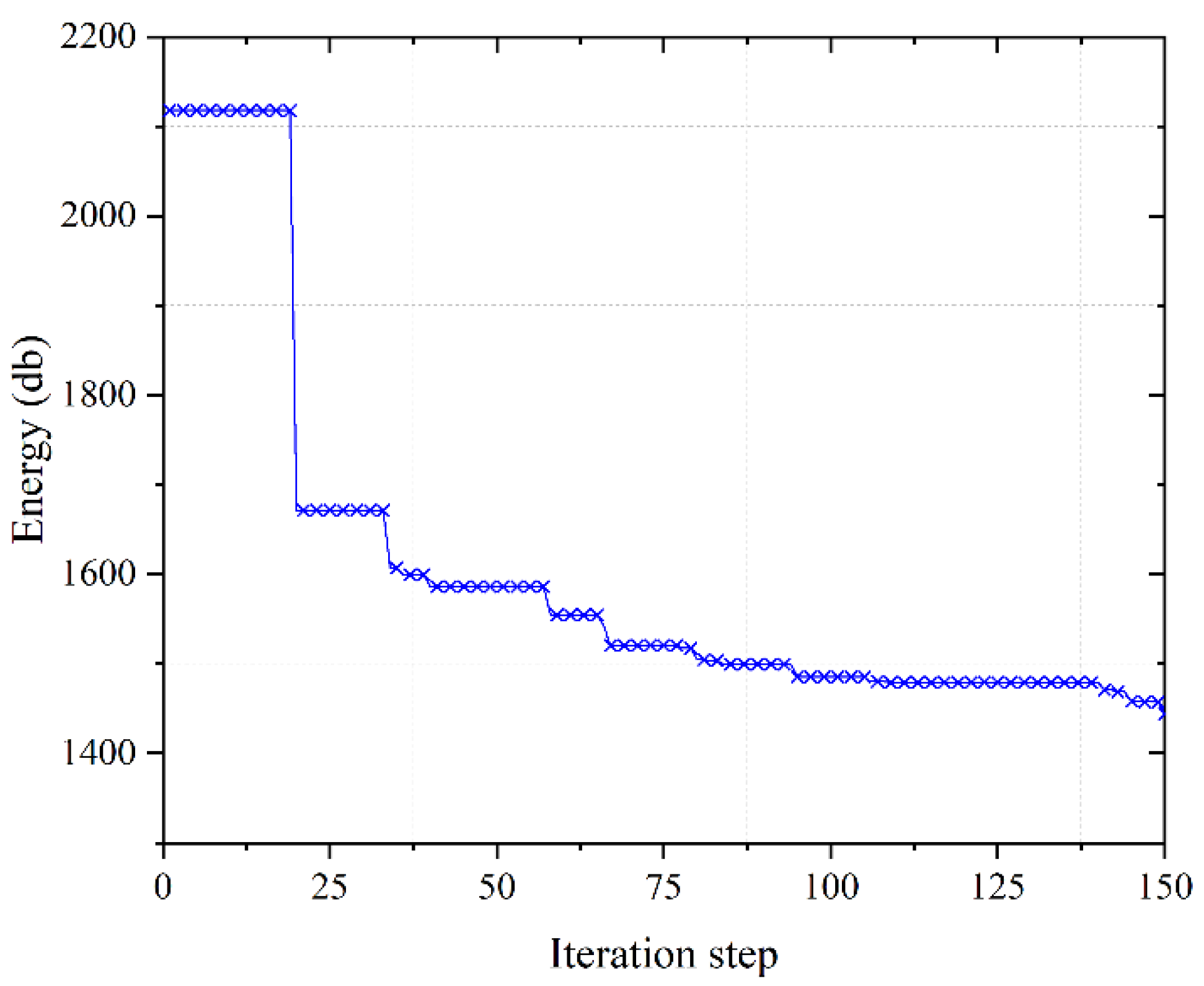
Furthermore, the global POD ROM is used instead of the FOM for the vibration reduction optimization design of the PAF structure. In the optimization design stage, 50 sample configurations are selected to calculate the corresponding responses to construct the initial Kriging surrogate model. The upper limit of iteration is 300. The iteration stops when the maximum number of iteration steps is reached or Formula (27) is satisfied. The iterative convergence curve is shown in Figure 19.
The optimized results are shown in Table 3. The optimized configuration can ensure that the first-order resonant frequency and mass satisfy the constraints, while the energy sum of the interest frequency range decreases significantly. The optimized energy sum of the interest frequency range is 1450.0 db, which is 31.5% lower than the initial value (2117.8 db). The optimized configuration has no resonance frequency in the [95 Hz, 105 Hz], and the energy–frequency curve has no peak value in this frequency range, which is also the main reason why the energy sum of interest decreases significantly. Figure 20 shows the energy–frequency curves before and after the vibration reduction optimization of the PAF structure. The energy–frequency curve of the optimized configuration is calculated based on the global POD ROM and the FOM, which almost completely coincide with each other. The Te is 1439.72 db and 1450.0 db, respectively, and the relative error is only 0.7%. The accuracy and credibility of the optimized analysis results based on the global POD ROM are verified.
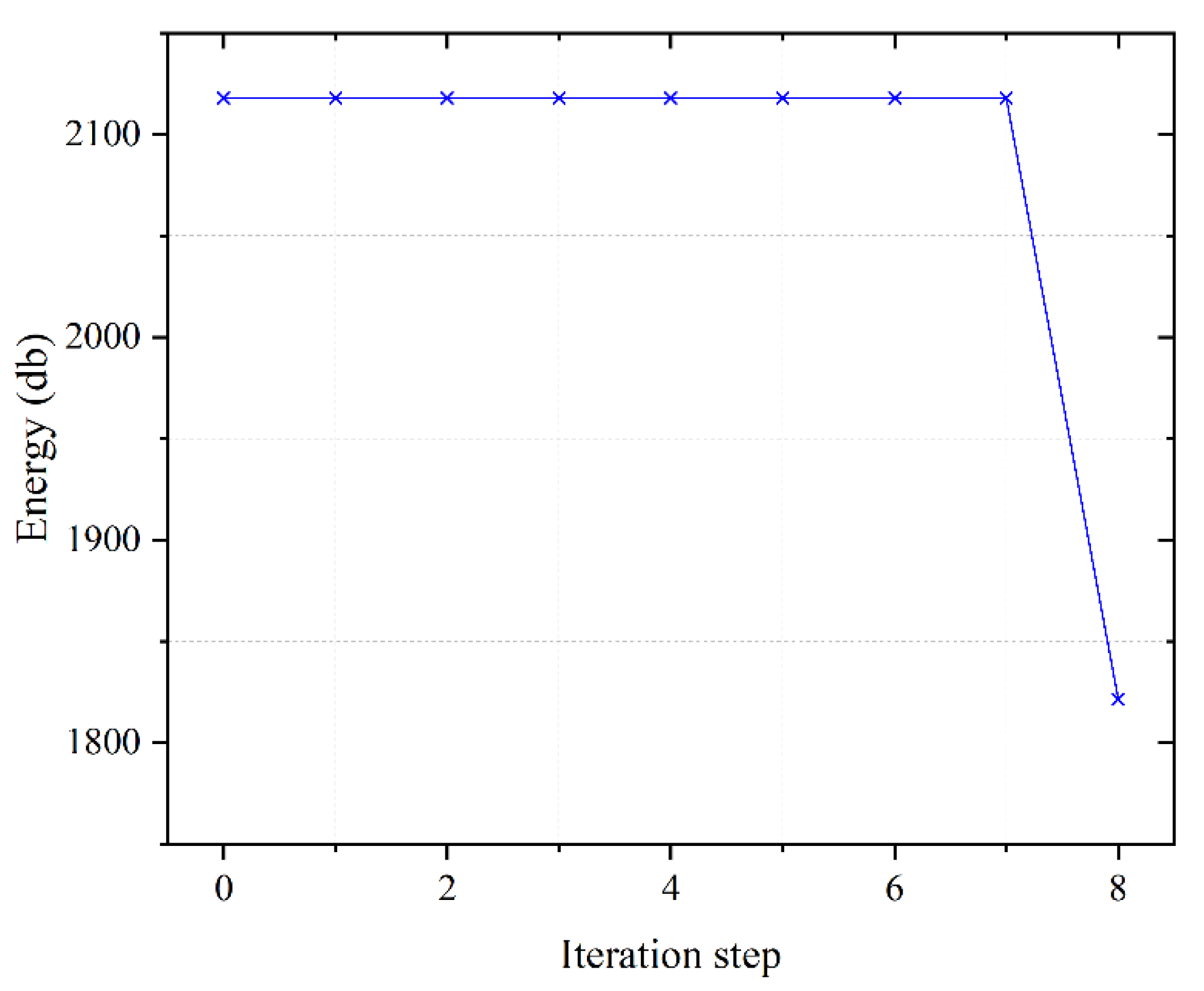
Next, the optimization ability of the global POD ROM is discussed. In the offline stage, it takes 28.4 h to construct the global POD ROM. In the online stage, the vibration reduction optimization based on the global POD ROM uses 50 initial sample configurations to construct the initial surrogate model. The optimization iteration is 150 steps, and the time is 7.7 h, so the total time is 36.1 h. However, with the same time-consuming condition, the FOM can only finish 23 frequency response analyses, and it is difficult to complete the initial sampling if the same 50 initial samples are used. For comparison, 15 sample configurations are used to construct the initial surrogate model, and eight steps of optimization iteration are performed. The convergence curve is shown in Figure 21, and the optimization results are shown in Table 3. By comparison, the vibration reduction optimization result based on the global POD ROM are reduced by 20.0% compared with that directly using the FOM, which verifies that the proposed approach has better optimization ability.

6. Conclusions

This paper proposes a framework for vibration reduction optimization based on the global POD ROM to address the problem of low efficiency in vibration reduction optimization of complex thin-walled aerospace structures. When the frequency response analysis accuracy of the global POD ROM constructed by the initial reduced basis is insufficient, the CV–Voronoi sequence sampling method is used to adaptively update the global POD ROM until it meets the global accuracy requirements of the design space. In the optimization process, the global POD ROM is used to replace the FOM for frequency response analysis, and an EGO algorithm based on the surrogate model is used to accelerate the optimization process. The conclusions of this paper are as follows:
(1)
For the global POD ROM: The calculation accuracy and efficiency of the proposed approach are verified by the vibration reduction optimization examples of the S-shaped curved stiffened shell and PAF. The RMSE of the dynamic response is calculated by random sampling in the design space, which verifies that the global POD ROM has high accuracy in the global design space. Compared with the FOM, the dynamics analysis based on the global POD ROM reduces the single mean calculation time by more than 96.9% and 97.6%, respectively, which has a significant computational efficiency advantage.
(2)
For vibration reduction optimization: In the S-shaped curved stiffened shell and PAF vibration reduction optimization examples, the optimized result in satisfied mass and first resonance frequency constraint decreased by 79.6% and 31.5% of objective energy, respectively, when compared to the initial results. It shows that this method is effective for vibration reduction optimization in complex thin-walled structures. For the vibration reduction optimization of the S-shaped curved stiffened shell, the optimization results of the global POD ROM are reduced by 58.8% in the same time period compared with the FOM method. For PAF structures, compared with the FOM method, the vibration reduction optimization results of the global POD ROM are reduced by 20.0% in the same time period. It shows that the proposed approach has a stronger optimization ability.
The subsequent work will carry out a more efficient research method for adaptively updating global POD ROM, including optimizing the add-point strategy and reduced basis updating scheme and using advanced intelligent algorithms for high-dimensional design space to improve the parameter optimization ability on the current basis.

Author Contributions

Conceptualization, Y.S.; Data curation, Z.K.; Formal analysis, Y.S., Z.K. and P.Z.; Funding acquisition, K.T.; Project administration, Z.K., W.S., Q.Y. and K.T.; Supervision, K.T.; Validation, Y.S. and K.T.; Visualization, Z.K., P.Z. and Y.S.; Writing—original draft, Y.S. and Z.K.; Writing—review & editing, K.T., W.S. and P.Z. All authors have read and agreed to the published version of the manuscript.

Funding

This work was supported by National Key Research and Development Program project of China; Grant Number: 2022YFB3404700. National Natural Science Foundation of China; Grant Number: 11902065. Basic research funds for the central universities of China; Grant Number: DUT21RC(3)013.

Institutional Review Board Statement

Not applicable.

Informed Consent Statement

Not applicable.

Data Availability Statement

The data and procedures of this study are not uploaded to the public website. The research data can be obtained by contacting the corresponding author of this paper via email.

Conflicts of Interest

The authors declare that there are no conflict of interest.

References

  1. Léné, F.; Duvaut, G.; Olivier-Mailhé, M.; Ben Chaabane, S.; Grihon, S. An advanced methodology for optimum design of a composite stiffened cylinder. Compos. Struct. 2009, 91, 392–397. [Google Scholar] [CrossRef]
  2. Tanishima, N.; Okamoto, H.; Iki, K.; Watanabe, K.; Okumura, T.; Kato, H.; Hayashi, M.; Hirano, D. Concept and design of the caging-based debris gripper for PAF capturing. J. Space Saf. Eng. 2020, 7, 358–363. [Google Scholar] [CrossRef]
  3. Chen, S.; Yang, Z.; Ying, M.; Zheng, Y.; Liu, Y.; Pan, Z. Parallel load-bearing and damping system design and test for satellite vibration suppression. Appl. Sci. 2020, 10, 1548. [Google Scholar] [CrossRef] [Green Version]
  4. Tian, K.; Li, H.; Huang, L.; Huang, H.; Zhao, H.; Wang, B. Data-driven modelling and optimization of stiffeners on undevelopable curved surfaces. Struct. Multidiscip. Optim. 2020, 62, 3249–3269. [Google Scholar] [CrossRef]
  5. Hu, W.; Wu, J.; Zhu, Q.; Shen, J.; Zheng, X. Vibration suppression for flexible plate with tunable magnetically controlled joint stiffness/damping. Appl. Sci. 2022, 12, 11483. [Google Scholar] [CrossRef]
  6. Liu, W.; Mahfoze, O.A.; Longshaw, S.M.; Skillen, A.; Emerson, D.R. Simulating slosh induced damping, with application to aircraft wing-like structures. Appl. Sci. 2022, 12, 8481. [Google Scholar] [CrossRef]
  7. Ma, Z.D.; Kikuchi, N.; Cheng, H.C. Topological design for vibrating structures. Comput. Methods Appl. Mech. Eng. 1995, 121, 259–280. [Google Scholar] [CrossRef]
  8. Zargham, S.; Ward, T.A.; Ramli, R.; Badruddin, I.A. Topology optimization: A review for structural designs under vibration problems. Struct. Multidiscip. Optim. 2016, 53, 1157–1177. [Google Scholar] [CrossRef]
  9. Zhao, J.; Wang, C. Dynamic response topology optimization in the time domain using model reduction method. Struct. Multidiscip. Optim. 2016, 53, 101–114. [Google Scholar] [CrossRef]
  10. Liu, H.; Zhang, W.; Gao, T. A comparative study of dynamic analysis methods for structural topology optimization under harmonic force excitations. Struct. Multidiscip. Optim. 2015, 51, 1321–1333. [Google Scholar] [CrossRef]
  11. Li, Z.; Su, X.; Tan, J.; Wang, H.; Wu, W. Multi-objective optimization of the layout of damping material for reducing the structure-borne noise of thin-walled structures. Thin-Walled Struct. 2019, 140, 331–341. [Google Scholar] [CrossRef]
  12. Madeira, J.F.A.; Araújo, A.L.; Soares, C.M.; Soares, C.M. Multiobjective optimization for vibration reduction in composite plate structures using constrained layer damping. Comput. Struct. 2020, 232, 105810. [Google Scholar] [CrossRef]
  13. Xu, Z.D.; Huang, X.H.; Xu, F.H.; Yuan, J. Parameters optimization of vibration isolation and mitigation system for precision platforms using non-dominated sorting genetic algorithm. Mech. Syst. Signal Process. 2019, 128, 191–201. [Google Scholar] [CrossRef]
  14. Wang, W.; Cheng, G.; Li, Q. Fast dynamic performance optimization of complicated beam-type structures based on two new reduced physical models. Eng. Optim. 2013, 45, 835–850. [Google Scholar] [CrossRef]
  15. Feeny, B.F.; Kappagantu, R. On the physical interpretation of proper orthogonal modes in vibrations. J. Sound Vib. 1998, 211, 607–616. [Google Scholar] [CrossRef]
  16. Lu, K.; Jin, Y.; Chen, Y.; Yang, Y.; Hou, L.; Zhang, Z.; Li, Z.; Fu, C. Review for order reduction based on proper orthogonal decomposition and outlooks of applications in mechanical systems. Mech. Syst. Signal Process. 2019, 123, 264–297. [Google Scholar] [CrossRef]
  17. Wu, M.Y.; Wu, Y.; Yuan, X.Y.; Chen, Z.H.; Wu, W.T.; Aubry, N. Fast prediction of flow field around airfoils based on deep convolutional neural network. Appl. Sci. 2022, 12, 12075. [Google Scholar] [CrossRef]
  18. Su, Y.; Di, J.; Li, J.; Xia, F. Wind pressure field reconstruction and prediction of large-span roof structure with folded-plate type based on proper orthogonal decomposition. Appl. Sci. 2022, 12, 8430. [Google Scholar] [CrossRef]
  19. Rowley, C.W.; Colonius, T.; Murray, R.M. Model reduction for compressible flows using POD and Galerkin projection. Phys. D Nonlinear Phenom. 2004, 189, 115–129. [Google Scholar] [CrossRef]
  20. Ghoman, S.; Wang, Z.; Chen, P.; Kapania, R. A POD-based reduced order design scheme for shape optimization of air vehicles. In Proceedings of the 53rd AIAA/ASME/ASCE/AHS/ASC Structures, Structural Dynamics and Materials Conference 20th AIAA/ASME/AHS Adaptive Structures Conference 14th AIAA, Honolulu, HI, USA, 23–26 April 2012. [Google Scholar]
  21. Moore, J.; Cutright, S.; Viken, J.K. Structural design exploration of an electric powered multi-propulsor wing configuration. In Proceedings of the 58th AIAA/ASCE/AHS/ASC Structures, Structural Dynamics, and Materials Conference, Grapevine, TX, USA, 9–13 January 2017. [Google Scholar]
  22. Azam, S.E.; Mariani, S. Investigation of computational and accuracy issues in POD-based reduced order modeling of dynamic structural systems. Eng. Struct. 2013, 54, 150–167. [Google Scholar] [CrossRef]
  23. Benner, P.; Gugercin, S.; Willcox, K. A survey of projection-based model reduction methods for parametric dynamical systems. SIAM Rev. 2015, 57, 483–531. [Google Scholar] [CrossRef]
  24. Baur, U.; Beattie, C.; Benner, P.; Gugercin, S. Interpolatory projection methods for parameterized model reduction. SIAM J. Sci. Comput. 2011, 33, 2489–2518. [Google Scholar] [CrossRef] [Green Version]
  25. Gugercin, S.; Antoulas, A.C. A survey of model reduction by balanced truncation and some new results. Int. J. Control 2004, 77, 748–766. [Google Scholar] [CrossRef]
  26. Bamer, F.; Bucher, C. Application of the proper orthogonal decomposition for linear and nonlinear structures under transient excitations. Acta Mech. 2012, 223, 2549–2563. [Google Scholar] [CrossRef]
  27. Tian, K.; Wang, B.; Zhou, Y.; Waas, A.M. Proper-orthogonal-decomposition-based buckling analysis and optimization of hybrid fiber composite shells. AIAA J. 2018, 56, 1723–1730. [Google Scholar] [CrossRef]
  28. Tian, K.; Ma, X.; Li, Z.; Lin, S.; Wang, B.; Waas, A.M. A multi-fidelity competitive sampling method for surrogate-based stacking sequence optimization of composite shells with multiple cutouts. Int. J. Solids Struct. 2020, 193, 1–12. [Google Scholar] [CrossRef]
  29. Ritto, T.G.; Buezas, F.S.; Sampaio, R. A new measure of efficiency for model reduction: Application to a vibroimpact system. J. Sound Vib. 2011, 330, 1977–1984. [Google Scholar] [CrossRef] [Green Version]
  30. Li, Y.; Tian, K.; Hao, P.; Wang, B. Optimization design for vibration reduction of complex configuration structures via global reduced-order basis. Eng. Optim. 2021, 53, 1819–1833. [Google Scholar] [CrossRef]
  31. Humar, J. Dynamics of Structures, 3rd ed.; CRC Press: Boca Raton, FL, USA, 2012; pp. 399–477. [Google Scholar]
  32. Xu, S.; Liu, H.; Wang, X.; Jiang, X. A robust error-pursuing sequential sampling approach for global metamodeling based on voronoi diagram and cross validation. J. Mech. Des. 2014, 136, 071009. [Google Scholar] [CrossRef]
  33. Amine Bouhlel, M.; Bartoli, N.; Regis, R.G.; Otsmane, A.; Morlier, J. Efficient global optimization for high-dimensional constrained problems by using the Kriging models combined with the partial least squares method. Eng. Optim. 2018, 50, 2038–2053. [Google Scholar] [CrossRef] [Green Version]
  34. Kaymaz, I. Application of kriging method to structural reliability problems. Struct. Saf. 2005, 27, 133–151. [Google Scholar] [CrossRef]
  35. Jeong, S.; Murayama, M.; Yamamoto, K. Efficient optimization design method using kriging model. J. Aircr. 2005, 42, 413–420. [Google Scholar] [CrossRef] [Green Version]
  36. Cheng, W.; Wang, Z.; Zhou, L.; Sun, X.; Shi, J. Influences of shield ratio on the infrared signature of serpentine nozzle. Aerosp. Sci. Technol. 2017, 71, 299–311. [Google Scholar] [CrossRef]
  37. Liu, L.K.; Zheng, G.T. Parameter analysis of PAF for whole-spacecraft vibration isolation. Aerosp. Sci. Technol. 2007, 11, 464–472. [Google Scholar] [CrossRef]
  38. Ariane 5-Payload Adapter. Available online: https://www.esa.int/ESA_Multimedia/Images/2001/11/Ariane_5_-_payload_adapter (accessed on 20 November 2022).
  39. MSG-1 Is Installed on Its Payload Adapter, the ACU 1666 IN S5B Building. Available online: https://www.esa.int/ESA_Multimedia/Images/2002/08/MSG-1_is_installed_on_its_payload_adapter_the_ACU_1666_IN_S5B_building2 (accessed on 11 November 2022).
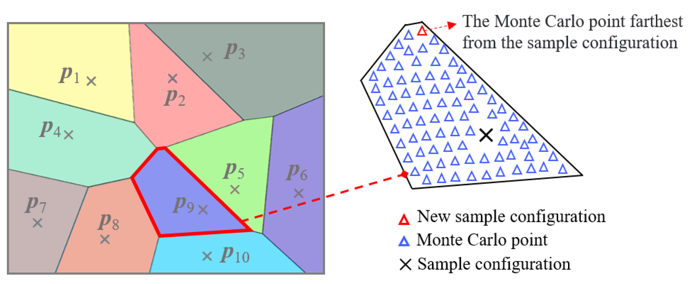
Figure 1. Voronoi diagram in two-dimensional space and Voronoi element by Monte Carlo point description.
Applsci 13 00472 g001
Figure 2. Flowchart of Efficient Global Optimization method.
Applsci 13 00472 g002
Figure 3. Flowchart of vibration reduction optimization approach accelerated by global POD ROM.
Applsci 13 00472 g003
Figure 4. Geometric parameters of the S-shaped curved stiffened shell structure: (a) reference line, and (b) cross-section along the reference line.
Applsci 13 00472 g004
Figure 5. Energy–frequency response of initial configuration calculated by the FOM of the S-shaped curved stiffened shell.
Applsci 13 00472 g005
Figure 6. Accuracy of the verified configurations computed by initial global POD ROM: (a) RMSE values; and (b) energy–frequency curves of the No.1 verified configuration.
Applsci 13 00472 g006
Figure 7. Maximum relative errors of the frequency response energy and the RMSE values of the energy–frequency curves of the FOM and the test ROM.
Applsci 13 00472 g007
Figure 8. Accuracy of the verified configurations computed by updated global POD ROM: (a) RMSE values; and (b) energy–frequency curves of the No.2 verified configuration.
Applsci 13 00472 g008
Figure 9. RMSE of verification configuration calculated by ROM constructed with CV–Voronoi sequence sampling and LHS direct sampling.
Applsci 13 00472 g009
Figure 10. Iterative convergence curve for vibration reduction optimization of the S-shaped curved stiffened shell (ROM).
Applsci 13 00472 g010
Figure 11. Energy–frequency response curves of the S-shaped curved stiffened shell before and after optimizations.
Applsci 13 00472 g011
Figure 12. Iterative convergence curve for vibration reduction optimization of the S-shaped curved stiffened shell (FOM).
Applsci 13 00472 g012
Figure 13. Schematic diagram of PAF [38,39].
Applsci 13 00472 g013
Figure 14. Geometry parameters of PAF.
Applsci 13 00472 g014
Figure 15. Energy frequency response of initial configuration calculated by FOM of PAF.
Applsci 13 00472 g015
Figure 16. Accuracy of the verified configurations computed by initial global POD ROM: (a) RMSE values; and (b) energy–frequency curves of No.13 verified configuration.
Applsci 13 00472 g016
Figure 17. Accuracy of the verified configurations computed by updated global POD ROM: (a) RMSE values; and (b) energy–frequency curves of No.3 verified configuration.
Applsci 13 00472 g017
Figure 18. RMSE of verification configuration calculated by reduced-order model constructed with CV–Voronoi sequence sampling and LHS direct sampling.
Applsci 13 00472 g018
Figure 19. Iterative convergence curve for vibration reduction optimization of the PAF (ROM).
Applsci 13 00472 g019
Figure 20. Energy frequency response of the PAF structure before and after optimization.
Applsci 13 00472 g020
Figure 21. Iterative convergence curve for vibration reduction optimization of the PAF (FOM).
Applsci 13 00472 g021
Table 1. The computation time and the maximum energy relative error of the initial configuration frequency response analysis using different methods.
Global POD ROMModal Superposition MethodModal Acceleration Method
Computation Time [s]114.6436.2562.3
Maximum Energy Relative Error [%]0.5202.32.0
Table 2. Vibration reduction optimization results of the S-shaped curved stiffened shell.
Lower BoundUpper BoundInitial ValueOptimized Value
(ROM)
Optimized Value
(FOM)
S1 [mm]1.504.503.001.50 4.50
S2 [mm]1.504.503.003.68 4.12
S3 [mm]1.504.503.004.48 2.01
S4 [mm]1.504.503.002.93 1.50
S5 [mm]1.504.503.004.50 2.23
T1 [mm]1.504.503.001.50 3.76
T2 [mm]1.504.503.001.70 1.64
T3 [mm]1.504.503.001.66 3.78
T4 [mm]1.504.503.003.43 2.63
T5 [mm]1.504.503.003.11 4.40
Ta [mm]1.504.503.004.23 2.61
Te [db]--1409.2287.0695.8
mass [kg]--657.92657.74635.19
resonant frequency [Hz]--60.160.265.8
Table 3. Vibration reduction optimization results of PAF.
Lower BoundUpper BoundInitial ValueOptimized Value
(ROM)
Optimized Value
(FOM)
T1 [mm]1.504.503.004.504.39
T2 [mm]1.504.503.004.273.39
T3 [mm]1.504.503.003.403.72
T4 [mm]1.504.503.002.562.15
T5 [mm]1.504.503.004.473.74
T6 [mm]1.504.503.003.111.50
T7 [mm]1.504.503.001.502.97
T8 [mm]1.504.503.001.522.94
T9 [mm]1.504.503.001.973.27
Te [db]--2117.81450.01821.4
mass [kg]--5.645.595.59
resonant frequency [Hz]--37.640.639.2
Disclaimer/Publisher’s Note: The statements, opinions and data contained in all publications are solely those of the individual author(s) and contributor(s) and not of MDPI and/or the editor(s). MDPI and/or the editor(s) disclaim responsibility for any injury to people or property resulting from any ideas, methods, instructions or products referred to in the content.