Abstract
This paper proposes a novel scheme titled ‘selective exchange of the worn cutting edge (SEWCE),’ which uses the cutting edge for an extended time by replacing the worn-out edge. This possibility was investigated for single-edge cutting tools for several operations, such as oblique and orthogonal cutting. The unique design of the turning tool incorporating cylindrical inserts was developed, thereby providing new machining possibilities compared to marketed solutions for round inserts. The prototype tool was prepared for the demonstration by using a cylinder with radius rε = 1.5 mm. A detailed analysis of the contact-zone cutting edge was performed considering a theoretical number of edges for different strategies. With this, the possibility for reusing the cutting element by resharpening the rake surface by up to ‘20x’ was achieved. Additionally, round inserts can be efficiently used in this developed scenario by turning them to compensate for the worn parts of the cutting tools. Therefore, by rotating, the deformed section of the cutting tool can be eliminated, and the number of edges can be created, directly reducing tool costs. Ultimately, conserving the health of a cutting tool brings many advantages, such as extending useful remaining lifetime, improving the surface quality and dimensional accuracy of machine parts, etc.
1. Introduction
Environmental issues are linked to modern technology, especially with the need for a significant amount of energy and cost in the manufacturing processes of individual products and the tools used to fabricate them. The tool costs cover a significant part of the total outcome of the machining process. Reduction in these costs is achieved mainly by improving the tools and their geometry [1,2,3], tool materials [1,2,3], lubricating the edge, and optimizing the cutting parameters using artificial intelligence [4,5,6], among others. The techniques used for removing material from the workpiece have a wide span and involve numerous mechanisms/styles with which the cutting tool and workpiece interact. The quality of the machined parts is based on the performance of three elements, such as machine tools, workpiece materials, and cutting tools, as they play a critical role in the capability and performance. Additionally, standard input parameters such as speed, feed, and depth of cut set by experts are equally significant in reducing inconsistency in machining. However, anomalous moments evolved during machining due to the material-based variations, failure of rotating machine elements assisting machining, etc., which are difficult to avoid. In addition, the effect of temperature and pressure on material properties makes machining more complex. This affects overall machining, including cutting tool edges, the surface finish of the workpiece, and ultimately the cost involved. Moreover, owing to their peculiar nature, they are challenging to monitor and forecast. Let it be any operation, such as grinding, milling, broaching, turning, boring, and turning, knowing material properties, machining mechanisms, and technological situations stands inevitable to improve overall performance. Examining this subject from the perspective of diversified modern sectors, such as automotive, space, aeronautics, medicine, medical, etc., the parts manufactured for these areas require excellent surface qualities. To obtain such properties, it is essential to create ideal cutting conditions in terms of the geometry and material of the cutting tool, cooling and lubricating mediums, correctly selected cutting parameters, etc. All these contributors affect the cutting performance slightly or greatly depending on the material properties and type of the process, namely roughing, finishing, precision leveling, etc. In this complex machining technology, tool wear is a critical factor due to its correlation with surface-related characteristics such as roughness, topography, waviness, residual stress, etc. The definition of tool life addresses the helpful utilization of a cutting tool. The conserving the health of the cutting tool is of great importance, not only to benefit from it in maximum time, but also to protect the machined surface from detrimental impacts. Therefore, researchers have repeatedly focused on models to improve the life of the tool.
Using a neural network approach, Laghari et al. [7] investigated life prediction and modeling of a carbide tool during turning of composite material. They stated that the results of the tool-life model calculated with the artificial neural network are very close to the physical experiment results and that the artificial neural network model predicts the experimental results with minimum error. Feito et al. [8] have analyzed the machinability of composite materials using the neural network approach. Kuntoğlu et al. [9] studied surface roughness of AISI 5140, modeling cutting parameters and tool geometry by means of response surface methodology for multicriteria optimization of vibration generated during machining. Younas et al. [10] investigated the optimum cutting parameters required for turning Ti6Al4V material. Their study was carried out in dry cutting conditions using uncoated H13 carbide inserts according to wear rate, specific cutting energy, material removal rate, and roughness. They stated that optimized machining conditions increased material removal rate by 34% and tool life by 7%, while reducing specific cutting energy by 6% and surface roughness by 2%. Singh et al. [11] studied the machining of Inconel 625 alloy under a minimal amount of nanofluid lubrication. The aim of their work was to reduce roughness and wear under several cutting environments. Tool performance was compared with dry and flooded conditions under a minimal amount of nanofluid lubrication, and it was determined that tool life and surface quality gave better results. Alliche et al. [12] investigated the effects of lubrication on machinability by artificial aging applied to A356 casting alloys. They stated that tool life increases at low cutting speeds and dry machining conditions, and that lubrication during the process increases the surface quality and extends the tool life. Orra and Choudhury [13] investigated the tribological aspects of microextrusions with various geometric shapes in the cutting tool in order to improve tool life in hard turning. Fang and Xu [14] in their study, examined the developments in the micro- and nanocutting process according to the effect of material properties and tool edge. Ginting et al. [15] investigated the turning of AISI 4340 material according to the properties of PVD- and CVD-coated carbide tools. The aim of this study was to increase the productivity of coated carbide tools in the machining of hardened steel. Efficiency was evaluated according to material removal rate and removal volume. Agrawal et al. [16] evaluated the comprehensive analysis of surface roughness, tool wear, machining cost, carbon emissions, and tool life in the turning of Ti6Al4V alloy under cryogenic and wet machining conditions. Aramesh et al. [17] conducted experimental studies to increase tool life and reduce chip formation during machining of Inconel 718 superalloy. In their study, they processed an aluminum–silicone workpiece in less than two seconds before machining. Thus, a very thin aluminum–silicone layer was formed on the tool surface during the preprocessing process, and during the Inconel process, aluminum–silicone melted due to high temperatures, channeling itself into microcracks on the tool surface and preventing their spread. As a result, they stated that chip formation was significantly reduced and an overall improvement in tool life occurred. Liu et al. [18] investigated the cutting performance comparison of microtextured WC-10Ni3Al and WC-8Co cutting tools in turning Ti6Al4V material. As a result, they stated that microtextures effectively reduced the cutting temperature and forces, decreased the adhesion on the rake surface, and extended the tool life at high cutting speeds. Varghese et al. [19] studied the performance of maraging steel during milling of AlCrN- and AlTiN-coated, cemented carbide cutting tools in dry, wet, and cryogenic environments. Luo et al. [20] studied the improvement of tool life during multiaxial milling of a nickel-based superalloy with a ball nose cutter based on active cutting-edge shift strategy. Marques et al. [21] evaluated the effect of adding solid lubricant to vegetable base oil applied with MQL when turning Inconel 718 with whisker-reinforced ceramic cutting tools. Their work was evaluated according to tool life, tool wear mechanisms, surface integrity, and cutting force. As a result, they stated that the addition of MoS2 improved the tool life. Mikolajczyk et al. [5] conducted studies to predict cutting tool life in turning operations using image processing and neural networks. Shokrani et al. [22] investigated hybrid cryogenic minimum-quantity lubrication to improve tool life in machining Ti6Al4V alloy. Sirin et al. [23] evaluated the machinability performances of X-750 nickel alloy under dry, minimum-quantity lubrication, and hBN-mixed nanofluid-minimum quantity of lubrication with a SiAlON ceramic cutting tool. In another study, Yıldırım et al. [24] examined the effect of adding hBN nanoparticles to nanofluid-minimum spoilage on tool life, tool-wear patterns, temperature, and roughness in turning Inconel 625. As a result of their studies, they stated that 0.5% vol. hBN nanofluid gives good values for low roughness and tool wear and extended tool life. Parida and Maity [25] conducted an experimental study on chip morphology and cutting tool life in hot machining of Monel-400 material. They carried out their studies according to different processing parameters and heating temperatures. Aramesh et al. [26] carried out a study on the useful tool-life estimation of worn tools with different machining parameters. For the prediction, they developed a proportional hazards model based on Weibull. As a result of their studies, they compared the accuracy of the developed model with the experimental data and stated that it was safe. Khanna et al. [27] studied the drilling of Inconel 718 alloy according to a sustainable manufacturing process to determine the potential for cryogenic machining. They determined that cryogenic machining increased tool life up to 87.50%. As can be understood from this summarized literature review, various options were applied to elongate the tool life in machining operations. This paper proposes a new model for obtaining longer tool life, which is separated from the counterparts as it addresses an easy, effective, and cost-friendly approach.
The development of tools with a specific design using a continuous edge opens the possibility for using a new very effective way of increasing tool life. This method is based on the selective exchange of the worn cutting edge (SEWCE). This method was developed at the Bydgoszcz University of Science and Technology for tools with a continuous cutting edge—without a nose [28,29]. The principle of the SEWCE method is to replace a worn edge by moving it to remove a fragment of the edge that determines the roughness of the machined surface. Oblique cutting with a straight cutting edge is researched both with positive and negative edge inclination angles [29,30]. The SEWCE method was first used for longitudinal oblique turning with a single straight edge (λs = −60°) [28]. In the trial, the wear criterion was VB = 0.2 mm because of the inclination angle and corresponding sliding distance of 0.3 mm. The worn cutting edge was moved in the specified displacement, such as ‘dl’ of the active part of the cutting edge ‘l’. Elongations of dl = (1.0, 0.5, 0.33, and 0.2) were assumed. The results show the possibility for a very significant increase in tool life, especially for dl = 0.2. Tool life for cutting using the SEWCE effect was similar to tool life obtained for the new cutting edge. Using a straight cutting edge, a positive flat angle αf was obtained when the edge was displaced, which promotes its reuse. A virtual model of the special tool for oblique cutting using a straight cutting edge with a special mechanism for moving the cutting insert was represented. The concept of using SEWCE for a circle handle insert was presented in [28]. The paper shows both theories of the SEWCE concept, which uses a circle insert in orthogonal cutting, and the experiment results. Mikolajczyk et al. [28] identify the edge fragment shaping the surface roughness according to the geometric and kinematic mapping of the edge (GKME) as the smallest renewal movement of the edge, and the hatch of the entire contact ensures complete edge replacement. However, the presented test results indicate that a higher edge rotation is necessary. The authors explain this by the influence of additional cutting-edge wear phenomena mainly related to the hardening of the machined surface [3]. The results indicate that it is advisable to conduct further research into the wear process of a continuous edge, and to search for new applications of the presented SEWCE effect for a significant increase in tool life and reduction in its cost.
The paper presents the basis for the optimization of single cutting edges in the shape of a circle using the SEWCE effect developed at the Bydgoszcz University of Science and Technology [28,29]. In the article, based on the practical range of the insert dimensions used, graphs showing the effect of radius of insert and feed f on the angle are presented. The in-depth SEWCE analysis of the phenomenon, based on the existing solutions for the diameters used, represents a significant advance compared with the authors’ previously presented work [28]. It opens a new field of research on implementing the SEWCE effect for marketed tools.
This article shows a design solution for an unconventional folding tool with a cylindrical cutting element. The new tool allows for the use of the SEWCE effect and the possibility to sharpen the tool surface repeatedly to increase tool life. Analyses for a tool with a cylindrical element having radius rε = 1.5 mm are presented. In Section 2, an idea for increasing tool life by different replacement strategies for the active section of the cutting edge is presented. Section 3 presents the idea of a special tool for increasing tool life by using the SEWCE effect. Section 4 contains the development of the new tool and the results of an analysis of the tool’s potential for increased sustainability. Section 5 presents the article’s conclusions.
2. Basis of Increased Tool Life by Selective Exchange of Worn Cutting Edge—SEWCE Effect
Tools are increasingly used with edges in the form of round inserts [1,3,28]. For this insert, it is possible to apply the method of restoration of worn cutting edges by the SEWCE effect [28]. This insert is used especially in and near orthogonal cutting for turning or milling. The main advantage provided by this special tool is to develop an effective cutting ability, producing good surface roughness owing to the large tool tip radius [1,3,28].
Figure 1 shows the edge circle view, which is appropriate to make an analysis of the contact conditions between the cutting edge and the surface area during orthogonal cutting. The arc between points A and B’ limits the contact conditions between the cutting edge and the machined surface. This addresses an angular part of the cutting-edge corners with a radius rβ and an angle α + β. The cutting-edge part—arc BB’ with an angle-2α—is critical to the state of the surface texture formation and in this respect it is the development of surface roughness Rzt, which can be achieved based on geometric and kinematic mapping of the edge GKME from Equation (1) [3,31,32]:
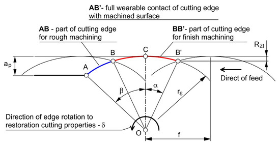
Figure 1.
Presentation of contact conditions between the cutting edge and workpiece surface.
The values for angles α and β can be found according to Equations (2) and (3) [28]:
where rε represents the cutting-edge radius of the cutting tool, f is the feed rate, and ap addresses the depth of cut value.
Based on analysis of Equation (2), we can see that angle α depends on feed f and radius of insert rε. From the analysis of Equation (3), we can observe that the β value depends on ap and rε. Round inserts are produced in a wide range of diameters. For example, Sandvik Coromant produces round inserts: T-Max® P system RCMX type (cylindrical–Figure 2a) for 10, 12, 16, 20, 26, 32 mm diameter; and the CoroTurn® 107 system RCMT-type (cone shape—Figure 2b) for 05, 06, 08, 10, 12, 16, 20, 25, 32 mm diameter. Based on the practical range of insert dimensions used, graphs showing the effect of the radius of insert rand feed f on angle α (Figure 3) and ap on angle β (Figure 4) were drawn. The in-depth SEWCE analysis of the phenomenon, based on the existing solutions for the diameters used, as shown in Figure 3 and Figure 4 and the following figures, represents a significant advance compared with our previous work [28].
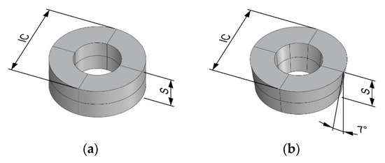
Figure 2.
Round inserts produced by Sandvik Coromant [33]: (a) T-Max® P system RCMX type (IC = 10, 12, 16, 20, 26, 32 mm); (b) CoroTurn® 107 system RCMT type (IC = 05, 06, 08, 10, 12, 16, 20, 25, 32 mm).
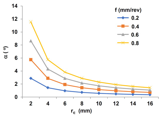
Figure 3.
Effect of insert radius rε and feed f on angle α.

Figure 4.
Effect of insert radius rε and ap on angle β.
We can consider two main cases for replacing a worn edge section:
- Complete, by rotating the insert through the angle δ = α + β;
- Partial, by rotation of the insert through an angle contained within the limits 2α < δ < α + β.
The total variation in the cutting-edge actuation can be obtained by turning the round end tip at a certain angle as can be equated by the formulation of δ = α + β (Figure 1)—the contact conditions between the tool and workpiece. However, this change does not ensure that the intensification of the work structure from the boundary of the cutting movement is cut off [1].
The theoretical number of edges that can be obtained for a full circuit cutting edge (360°) with full exchange of contact can be determined from the following formula [28,29]:
Graphs prepared using Equation (4) are presented in Figure 5.
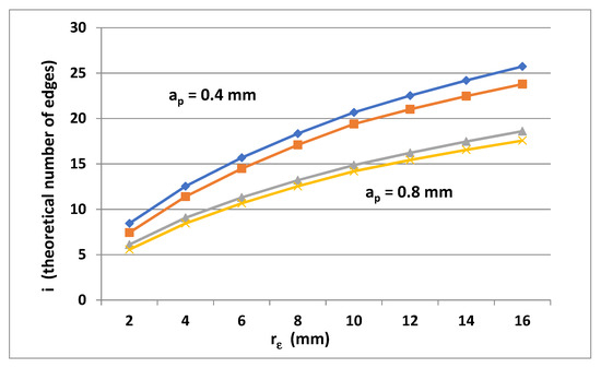
Figure 5.
Theoretical number of edges determined by using the round insert α + β rotation for different rε, f, and ap values.
Based on idea of SEWCE, however, we can change only part of the cutting edge, which creates surface roughness Rzt. The theoretical number of edges achieved using this strategy can determined from:
as presented in the graphs shown in Figure 6.
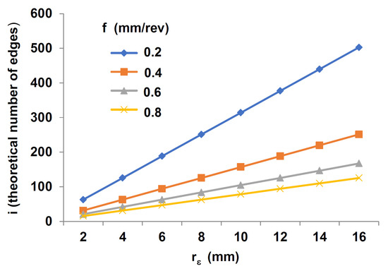
Figure 6.
Theoretical number of edges determined by using the round insert δ = 2α rotation for different rε and f values.
An area of possibility for applying different SEWCE strategies is presented in Figure 7.
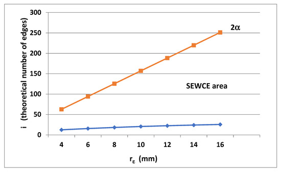
Figure 7.
Example of SEWCE area for a round insert: 2 < rε < 16, for f = 0.4 mm/rev and ap = 0.4 mm.
Restoration of the cutting edge within the GKME does not, however, ensure the displacement of the cutting edge within the scope of concentrated edge wear from the surface of the machined surface [3].
In a previous article [28], research on the minimum round insert rotation for obtaining the initial surface roughness was presented. In the study, a round insert rε = 6 mm (tool-PAFANA SRDCN 2525-12) was used. Machining of C45 steel was performed by using vc = 200 m/min, ap = 0.25 mm, and f = 0.2 mm/rev until the edge was worn out (VB = 0.4 mm) after a cutting time of 50 min. A short section of the surface was cut with the worn edge using different δ rotations of the edge relative to the starting position. The test results are shown in Figure 8 and compared with the calculated values for these trials 2α = 1°44′. We can observe that stabilization of surface roughness was obtained for δ = 4°. This is more than twice the value of 2α.
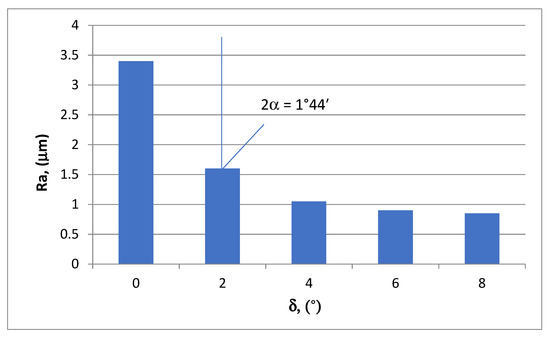
Figure 8.
Influence of the δ angle of rotation on the worn round insert (rε = 6mm). Ra is the surface roughness parameter.
Using larger values for the insert angle rotation permits extra reduction in the machined surface roughness. The cause of this can be explained by the plastic structure of the impact, and also the increasing width for the edge δ = 2α of the angle specified only in theory, resulting in a long processing zone for the dense edge. Further action is appropriate to determine the strength of the diluted boundary edge and the latest information on mechanical progress throughout this process.
3. Concept for a Special Tool to Increase the Tool Life by Considering the SEWCE Effect
The concept of increasing the edge duration by restoring the cutting properties of the edge by partially replacing the worn part of the cutting edge can be applied in practice by using existing tools with round inserts [1,3,32]. Manufactured cutting elements with a cutting edge and a circular arc, however, have a significant radius of cutting edge rε. The inserts used commercially have both a cylindrical and truncated cone shape, which provide a greater angle of attack, owing to the angle of application [28]. This corresponds to the commonly used inserts with straight corner edges [1,3].
Existing tool solutions with cutting edges and round edge, mainly used with a hole for fixing the insert, limits the possibility for reducing the radius of curvature of the circle. It has been proposed to solve this problem by using a cutting element with a different shape in the form of a cylinder, the base of which is the rake surface, and the cutting element can be fixed by a cylindrical surface (Figure 9a).
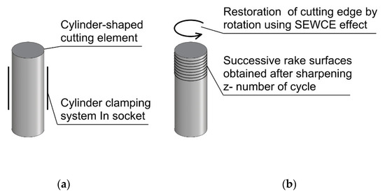
Figure 9.
The essence of restoring cutting-edge properties with a cylindrical cutting element: (a) design concept for the tool; (b) phases of using the rotation of the cutting element and sharpening the rake surface.
This shape of the insert, with its flat contact surface, allows the rotation of the cutting element to be used to reproduce the cutting properties, along with sharpening the contact surface after the entire circumference of the insert has been used and can be reused many times (Figure 9b). This new concept for cutting inserts, due to the clamping method, opens possibilities for reducing the diameter of the cutting element, which can be advantageous for the conditions of surface shaping by turning. This would not have been possible using commercial round plates of a much larger diameter.
In Figure 5 and Figure 6, graphs are presented that show strategies of SEWCE for δ = 2α and δ = α + β (Figure 7), theoretically decreasing the number of edges for the smaller radius rε. This affects the theoretical number of edges, but the use of a cylindrical cutting element in turn allows the entire circumference of the cutting edge to be reused after being worn down by sharpening the cutting edge z times. The number of edges can be determined for the δ = α + β strategy by modifying Equation (4):
where z is the number of resharpenings of the rake surface.
Similarly, Equation (5) for the δ = 2α strategy can be modified:
4. Results and Discussion
The concept for using a new kind of cutting insert based on its cylinder shape is described in this paper. The theory and analysis of this innovative design, which may increase tool life, is presented in this section.
4.1. Design of an Innovative Cutting Tool with a Cylindrical Insert
Based on the concept for using a new shape of cutting insert, the original design of tool was modified. The proposed solution is equipped with a cylindrical cutting element mounted in the holder (Figure 10). The structure developed allows for the rotation of the cutting element in the socket. This ensures that the cutting properties are restored by replacing completely or partially the worn part of the cutting edge.
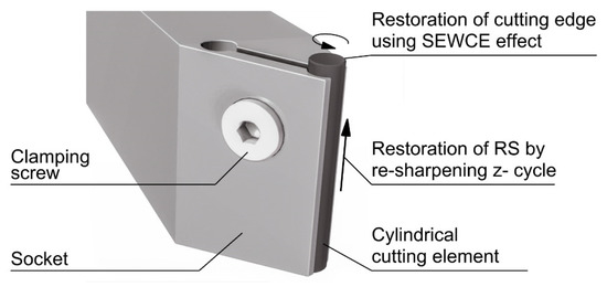
Figure 10.
A virtual model of the tool ensuring the reproduction of cutting properties using the SEWCE effect and resharpening of the rake surface (RS).
The shape of cutting inserts used allowed for a reduction in diameter compared to commercial solutions of round inserts. The smallest diameter—5 mm—holds a round insert CoroTurn® 107 system RCMT 05 02 M0. Based on the design developed, a prototype of a folding tool with a cylindrical element 3 mm in diameter (rε = 1.5 mm) was prepared from sintered carbide S30. The body of the tool was prepared from C45 upgraded steel using a section that was 24 × 22 mm (Figure 11a). The seat of the tool was located at an angle of γp = −6°, and λs = −6° was used for the tip of the cutting edge (point C) (Figure 11).
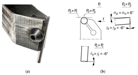
Figure 11.
Prototype of the special tool with its cylindrical insert: (a) view of tool prepared using ATOS II Triple Scan; (b) geometry of cutting edge.
The holder was prepared by making a hole with a diameter of 3 mm, the positioning of the hole axis was determined according to the adopted values for angles λs = −6° and γp = −6° (Figure 11b); along the axis of the socket, a 22 mm deep cut was made. A hole with a diameter of 3.5 mm was drilled in the tool holder parallel to the axis of the cutting element socket, thus ensuring that the socket could be deformed. Perpendicular to the surface of the cut, a through-going hole was drilled from the outside and then tapped. An M5 countersunk screw with a hexagonal socket was used for clamping.
The geometry of the tools was checked using ATOS II Triple Scan with two cameras 2 × 5,000,000 pixels (Figure 12). The measurement resulted in a stereo lithography file STL characterized by a dense mesh. The average mesh vertex distance for the surface of the cutting element was 0.08 mm. The measurements were taken using Rhinoceros 7 software. An example of the measuring procedure is presented in Figure 12b for angle ap. In order to measure the ap angle, a reference surface was determined, in this case the bottom surface of the tool body. The position of this surface was determined from the position of the extreme vertices of the mesh surface. A group of mesh surface vertices representing the extreme area at the bottom and top parts of the cutting element was then determined. For these points, a straight line was determined for which the ap angle was measured. Results of the measurements are shown in Table 1, which indicate high measurement accuracy and precision.
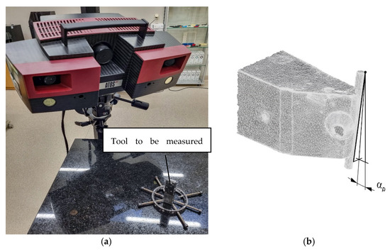
Figure 12.
ATOS II Triple Scan: (a) view of measuring setup, (b) an example showing the measurement of angle αp.

Table 1.
Results of cutting-edge geometry measurement.
A cylindrical element with a length of 35 mm was used. For the proposed tool design, this allows about z = 20 edge resharpenings, considering the part of the element necessary for attachment in the holder.
This tool was used for preliminary experiments of turning on a TUD 50 lathe (Figure 13). In the experiments, C45 steel was machined, with ap = 0.2 mm, cutting speed vc = 206.4 m/min, and different feed rates: f = 0.08, 0.19, and 0.27 mm/rev. In the trials, a microscopic method with a marker was used to control the position before and after rotation. Before rotation, the cylinder was unclamped by gripping the protruding part, rotated, and reclamped. Work is underway on a practical solution to control the rotation of the component. Measurements of the surface roughness parameter Ra were performed using a Mahr Gd 120 profilografometer (Figure 14) equipped with a magnetically fixed measuring needle (MFW 250B).
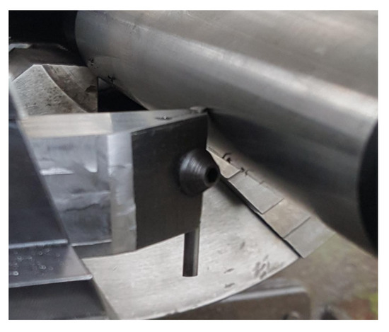
Figure 13.
Tool mounted in the holder of the TUD 50 lathe.
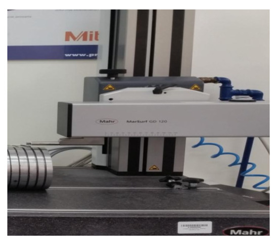
Figure 14.
Mahr Gd 120 profilografometer equipped with a magnetically fixed measuring needle (MFW 250B).
Results of the experiment are presented in Figure 15 and compared with theoretical values calculated using Equation (1) and divided by 4. This is the coefficient usually used. Note that the surface roughness decreases for the smallest values of feed. This can be explained by the effect of the minimum uncut chip thickness (MUCT), which causes that the height of the bumps can increase because of the influence of MUCT hmin [31,32] for small feed values. For rε = 1.5 mm feed, 0.08 mm/rev and 0.19 mm/rev are low values [32].
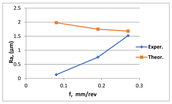
Figure 15.
Comparison of experimental and theoretical values for the surface roughness Ra parameter.
4.2. Analysis of Theoretical Possibility for Increased Tool Life by Using the Developed Tool
An analysis of the contact conditions between the cutting element and the machined surface was carried out for the developed tool.
Given the radius of the tool with a cylindrical element (rε = 1.5 mm), the values for 2α (Equation (1)) and α + β (Equation (2)) angles were calculated for different values of feed f. Figure 16 and Figure 17 show graphs of the results.
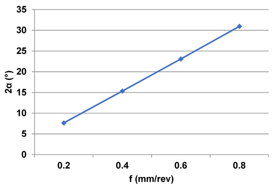
Figure 16.
Effect of feed on the 2α angle for rε = 1.5 mm.
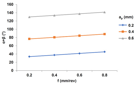
Figure 17.
Effect of feed on the α + β angle for rε = 1.5 mm.
Results of calculating the theoretical number of edges for the developed tool with a cylindrical element and rε = 1.5 mm are presented in Figure 18 for the δ = 2α strategy and in Figure 19 for the δ = α + β strategy. The theoretical results are presented from f = 0.2 mm/rev because, owing to the minimum uncut chip thickness effect of MUCT, it is not advisable to use small feed rates, as this increases the surface roughness, especially for a larger corner radius rε [31,32]. Different values for the resharpening number of cycles are presented. Because the β angle does not depend on feed, we can observe a very small effect of feed on i for the δ = α + β strategy. Figure 18 and Figure 19 were prepared using a different scales for i. For directly comparing the theoretical number of edges using SEWCE strategy, Figure 20 presents a comparison of results for the δ = 2α and δ = α + β strategies, given the middle value of z = 10 and feed f = 0.4 mm/rev.
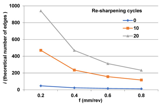
Figure 18.
Influence of feed rate on edges using the δ = 2α strategy for application of rε = 1.5 mm insert with a different number of resharpening cycles z.
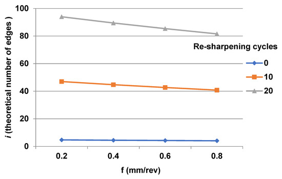
Figure 19.
Influence of feed rate on edges using the δ = α + β strategy for application of rε = 1.5 mm insert with a different number of resharpening cycles z.
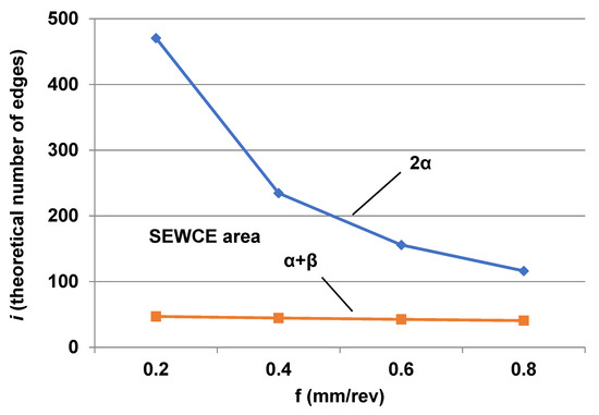
Figure 20.
Example of SEWCE area for the developed tool (rε = 1.5 mm) for z = 10 and ap = 0.4 mm.
This is only a theoretical comparison of a possible number of edges using SEWCE and the resharpening effect in applying the tool. Of course, to find the optimal solution, subsequent experimental research is needed to understand the actual process of cutting-edge wear and the application of the SEWCE effect. Previous research [28] found that it needs to use more than two times δ = 2α rotation to obtain surface roughness similar to the new edge. This ensures multiple increases in the hypothetical number of edges that can be obtained with the reproduction of cutting properties by partially replacing the worn part of the cutting edge. It also allows the entire cutting edge to be restored by sharpening the rake surface, ensuring a repeat cycle. The analysis of the developed tool shows the advantages of the new solution and demonstrates the possibilities for re-creating the cutting properties of its cutting edge. However, this requires confirmation through experimental studies. At the same time, the usefulness of the solution presented should be emphasized owing to obtaining a tool with a relatively small, i.e, much smaller than commercial, cutting-edge radius rε. This creates new opportunities for shaping the surface with cutting edges with a circular arc. The solution is characterized by a simple design ensuring a significant reduction in tool costs. The article opens a new area in research for achieving savings in cutting materials for environmental protection and reducing machining costs. Using a new tool solution with a cylindrical cutting element of a small diameter extends the possibilities for finishing with a circular cutting edge. The SEWCE presented for increasing tool life and reducing cost appears more effective than the conventional methods. It should be noted that this also applies to tools with a straight cutting edge.
This proposed concept for using the SEWCE effect for increasing tool life by controlled movement of a round continuous edge is presented in the article for point tools, but, of course, it is also possible to implement this solution for other multipoint tools that are equipped in round inserts. Additional research is needed to obtain optimal results. Perhaps this article cannot answer all enquiries, but this issue opens the field of research, which will enable significant savings to be achieved for the benefit of the environment by seeking to optimize the use of blade material while maintaining product quality.
5. Conclusions
Tool and machining cost reductions can be achieved by developing the current state of the tool and cutting element design, cutting materials, and optimizing machining conditions. This article presents a new way to re-create the cutting properties of cutting continuous edges with an arc-shaped cutting edge in orthogonal cutting. This is accomplished by using a selective exchange of the worn cutting edge—SEWCE. The scope of commercial round inserts with a large radius of rε (2.5 to 16 mm) and a specially developed tool with rε = 1.5 mm is analyzed in this article. The following items are the article’s main findings for edges with a curved cutting edge:
- The overall contact between the edge and the workpiece includes a fragment defined by angle 2α, which shapes the roughness of the machined surface through geometric and kinematic mapping of the edge (GKME) and part described by the β − α angle, which removes the machining allowance ap.
- The equations presented show that fragment 2α depends on feed rate f and radius of the cutting edge rε (Equation (2)), while part β − α depends on the depth of cut ap and the radius of the cutting edge rε (Equation (3)).
- We consider two boundary possibilities for opening the cutting properties of an edge: complete replacement of the edge contact by rotating the edge through an angle δ = α + β, and in the GKME area by rotation δ = 2α. The area between these strategies is referred to as the SEWCE area. Reducing the edge radius rε significantly reduces the theoretical number of edges i.
- Calculations of the theoretical number of edges i indicate that a very high number of edges is obtained, especially for strategy δ = 2α, while preliminary results available in the literature indicate that a higher value of δ angle rotation is needed due to edge wear in the theoretical contact.
- This paper presents an original solution for a tool with an circle-shaped cutting edge using a cylindrical cutting element with radius rε = 1.5 mm. This creates additional application possibilities for surface machining in comparison to marketed round inserts with larger rε.
- By using this new tool, the possibility for applying the SEWCE effect and, in addition, the possibility for reusing the cutting element by resharpening the rake surface by up to 20x was achieved. In this way, the possibility for obtaining a large number of edges has been achieved despite using a small radius for the cutting edge rε.
- The issue presented opens a new area of research in terms of exploring the possibility for a considerable increase in tool life using the application of the SEWCE effect for edges with a continuous cutting edge and by application of a cylindrically shaped insert. Future research should cover wear, machinability indexes, and the search for new design solutions.
Author Contributions
Conceptualization, T.M. and T.P.; methodology, T.M. and T.P.; software, T.M. and T.P.; validation, T.M., T.P., M.K., A.D.P. and R.B.; formal analysis, T.M., T.P., M.K., A.D.P. and R.B.; investigation, M.K., A.D.P. and R.B.; resources, T.M., T.P., M.K., A.D.P. and R.B.; data curation, T.M. and T.P.; writing—original draft preparation, T.M., T.P., M.K., A.D.P. and R.B.; writing—review and editing, T.M., T.P., M.K., A.D.P. and R.B.; visualization, T.M. and T.P.; supervision, T.M. and T.P.; project administration, T.M. and T.P.; funding acquisition, T.M. and T.P. All authors have read and agreed to the published version of the manuscript.
Funding
This research received no external funding.
Institutional Review Board Statement
Not applicable.
Informed Consent Statement
Not applicable.
Data Availability Statement
Not applicable.
Conflicts of Interest
The authors declare no conflict of interest.
Abbreviations
| GKME | geometric and kinematic mapping of the edge |
| MUCT | minimum uncut chip thickness |
| RS | rake surface |
| SEWCE | selective exchange of worn cutting edge |
| STL | stereo-lithography file |
| ap | deep of cut, mm |
| F | feed rate, mm/rev |
| rε | radius of cutting edge, mm |
| 2α | angle of finishing part of circle cutting edge, ° |
| β | angle of rough machining part of circle cutting edge, ° |
| α + β | angle of contact zone of edge with machined surface, ° |
| δ | angle of rotation of cutting element for obtain SEWCE effect, ° |
| i | number of edges on one cutting edge |
| z | number of resharpening cycles of rake surface |
| γo | angle of rake surface, ° |
| λs | angle of inclination of cutting edge, ° |
| hmin | minimal value of uncut chip thickness, μm |
References
- Cichosz, P. Cutting Tools; WNT: Warsaw, Poland, 2006. [Google Scholar]
- Latos, H. Geometric and Kinematic Flexibility of Cutting Tools; Publishing House of the Technical and Agricultural Academy: Bydgoszcz, Poland, 1997. [Google Scholar]
- Grzesik, W. Fundamentals of Cutting Construction Materials; WNT: Warsaw, Poland, 2018. [Google Scholar]
- Mikołajczyk, T.; Nowicki, K.; Kłodowski, A.; Pimenov, D.Y. Neural network approach for automatic image analysis of cutting edge wear. Mech. Syst. Signal Process. 2017, 88, 100–110. [Google Scholar] [CrossRef]
- Mikołajczyk, T.; Nowicki, K.; Bustillo, A.; Pimenov, D.Y. Predicting tool life in turning operations using neural networks and image processing. Mech. Syst. Signal Process. 2018, 104, 503–513. [Google Scholar] [CrossRef]
- Kuntoğlu, M.; Aslan, A.; Sağlam, H.; Pimenov, D.Y.; Giasin, K.; Mikolajczyk, T. Optimization and analysis of surface roughness, flank wear and 5 different sensorial data via tool condition monitoring system in turning of AISI 5140. Sensors 2020, 20, 4377. [Google Scholar] [CrossRef] [PubMed]
- Laghari, R.A.; Li, J.; Laghari, A.A.; Mia, M.; Wang, S.-q.; Aibo, W.; Poonam, K. Carbide tool life prediction and modeling in SiCp/Al turning process via artificial neural network approach. In IOP Conference Series: Materials Science and Engineering; IOP Publishing: Bristol, UK, 2019; Volume 600, p. 012022. [Google Scholar]
- Feito, N.; Muñoz-Sánchez, A.; Díaz-Álvarez, A.; Loya, J.A. Analysis of the machinability of carbon fiber composite materials in function of tool wear and cutting parameters using the artificial neural network approach. Materials 2019, 12, 2747. [Google Scholar] [CrossRef]
- Kuntoğlu, M.; Aslan, A.; Pimenov, D.Y.; Giasin, K.; Mikolajczyk, T.; Sharma, S. Modeling of cutting parameters and tool geometry for multi-criteria optimization of surface roughness and vibration via response surface methodology in turning of AISI 5140 steel. Materials 2020, 13, 4242. [Google Scholar] [CrossRef]
- Younas, M.; Jaffery, S.H.I.; Khan, M.; Khan, M.A.; Ahmad, R.; Mubashar, A.; Ali, L. Multi-objective optimization for sustainable turning Ti6Al4V alloy using grey relational analysis (GRA) based on analytic hierarchy process (AHP). Int. J. Adv. Manuf. Technol. 2019, 105, 1175–1188. [Google Scholar] [CrossRef]
- Singh, T.; Dureja, J.S.; Dogra, M.; Bhatti, M.S. Environment friendly machining of Inconel 625 under nano-fluid minimum quantity lubrication (NMQL). Int. J. Precis. Eng. Manuf. 2018, 19, 1689–1697. [Google Scholar] [CrossRef]
- Alliche, M.A.; Djebara, A.; Zedan, Y.; Songmene, V. Effect of Artificial Aging Treatment and Lubrication Modes on the Machinability of A356 Cast Alloys. Preprints 2019, 2019120338. [Google Scholar] [CrossRef][Green Version]
- Orra, K.; Choudhury, S.K. Tribological aspects of various geometrically shaped micro-textures on cutting insert to improve tool life in hard turning process. J. Manuf. Process. 2018, 31, 502–513. [Google Scholar] [CrossRef]
- Fang, F.; Xu, F. Recent advances in micro/nano-cutting: Effect of tool edge and material properties. Nanomanufacturing Metrol. 2018, 1, 4–31. [Google Scholar] [CrossRef]
- Ginting, A.; Skein, R.; Cuaca, D.; Masyithah, Z. The characteristics of CVD-and PVD-coated carbide tools in hard turning of AISI 4340. Measurement 2018, 129, 548–557. [Google Scholar] [CrossRef]
- Agrawal, C.; Wadhwa, J.; Pitroda, A.; Pruncu, C.I.; Sarikaya, M.; Khanna, N. Comprehensive analysis of tool wear, tool life, surface roughness, costing and carbon emissions in turning Ti–6Al–4V titanium alloy: Cryogenic versus wet machining. Tribol. Int. 2021, 153, 106597. [Google Scholar] [CrossRef]
- Aramesh, M.; Montazeri, S.; Veldhuis, S.C. A novel treatment for cutting tools for reducing the chipping and improving tool life during machining of Inconel 718. Wear 2018, 414, 79–88. [Google Scholar] [CrossRef]
- Liu, X.; Liu, Y.; Li, L.; Tian, Y. Performances of micro-textured WC-10Ni3Al cemented carbides cutting tool in turning of Ti6Al4V. Int. J. Refract. Met. Hard Mater. 2019, 84, 104987. [Google Scholar] [CrossRef]
- Varghese, V.; Akhil, K.; Ramesh, M.; Chakradhar, D. Investigation on the performance of AlCrN and AlTiN coated cemented carbide inserts during end milling of maraging steel under dry, wet and cryogenic environments. J. Manuf. Process. 2019, 43, 136–144. [Google Scholar] [CrossRef]
- Luo, M.; Luo, H.; Zhang, D.; Tang, K. Improving tool life in multi-axis milling of Ni-based superalloy with ball-end cutter based on the active cutting edge shift strategy. J. Mater. Process. Technol. 2018, 252, 105–115. [Google Scholar] [CrossRef]
- Marques, A.; Suarez, M.P.; Sales, W.F.; Machado, Á.R. Turning of Inconel 718 with whisker-reinforced ceramic tools applying vegetable-based cutting fluid mixed with solid lubricants by MQL. J. Mater. Process. Technol. 2019, 266, 530–543. [Google Scholar] [CrossRef]
- Shokrani, A.; Al-Samarrai, I.; Newman, S.T. Hybrid cryogenic MQL for improving tool life in machining of Ti-6Al-4V titanium alloy. J. Manuf. Process. 2019, 43, 229–243. [Google Scholar] [CrossRef]
- Şirin, Ş.; Sarıkaya, M.; Yıldırım, Ç.V.; Kıvak, T. Machinability performance of nickel alloy X-750 with SiAlON ceramic cutting tool under dry, MQL and hBN mixed nanofluid-MQL. Tribol. Int. 2021, 153, 106673. [Google Scholar] [CrossRef]
- Yıldırım, Ç.V.; Sarıkaya, M.; Kıvak, T.; Şirin, Ş. The effect of addition of hBN nanoparticles to nanofluid-MQL on tool wear patterns, tool life, roughness and temperature in turning of Ni-based Inconel 625. Tribol. Int. 2019, 134, 443–456. [Google Scholar] [CrossRef]
- Parida, A.K.; Maity, K. Experimental investigation on tool life and chip morphology in hot machining of Monel-400. Eng. Sci. Technol. Int. J. 2018, 21, 371–379. [Google Scholar] [CrossRef]
- Aramesh, M.; Attia, M.; Kishawy, H.; Balazinski, M. Estimating the remaining useful tool life of worn tools under different cutting parameters: A survival life analysis during turning of titanium metal matrix composites (Ti-MMCs). CIRP J. Manuf. Sci. Technol. 2016, 12, 35–43. [Google Scholar] [CrossRef]
- Khanna, N.; Agrawal, C.; Gupta, M.K.; Song, Q. Tool wear and hole quality evaluation in cryogenic Drilling of Inconel 718 superalloy. Tribol. Int. 2020, 143, 106084. [Google Scholar] [CrossRef]
- Mikolajczyk, T.; Romanowski, Ł. Optimisation of single edge tools exploitation process. Appl. Mech. Mater. 2013, 332, 431–436. [Google Scholar] [CrossRef]
- Mikolajczyk, T. Edge Properties Restoration in Cutting with Single Edge Tool. Acad. J. Manuf. Eng. 2013, 11, 72–77. [Google Scholar]
- Grzesik, W.; Żak, K. Investigations of surface textures produced by oblique machining of different workpiece materials. Arch. Mater. Sci. Eng. 2011, 52, 46–53. [Google Scholar]
- Wojciechowski, S. Estimation of Minimum Uncut Chip Thickness during Precision and Micro-Machining Processes of Various Materials—A Critical Review. Materials 2021, 15, 59. [Google Scholar] [CrossRef]
- Mikolajczyk, T. Modeling of minimal thickness cutting layer influence on surface roughness in turning. Appl. Mech. Mater. 2014, 656, 262–269. [Google Scholar] [CrossRef]
- Sandvik Coromant Turning Tool. T-Max® P, Round Inserts. CoroTurn® 107, Round Inserts. 2022. Available online: https://www.indiamart.com/svik-asia/sandvik-turning-tools.html (accessed on 27 November 2022).
Disclaimer/Publisher’s Note: The statements, opinions and data contained in all publications are solely those of the individual author(s) and contributor(s) and not of MDPI and/or the editor(s). MDPI and/or the editor(s) disclaim responsibility for any injury to people or property resulting from any ideas, methods, instructions or products referred to in the content. |
© 2022 by the authors. Licensee MDPI, Basel, Switzerland. This article is an open access article distributed under the terms and conditions of the Creative Commons Attribution (CC BY) license (https://creativecommons.org/licenses/by/4.0/).