Article

Slagging Characteristics of a Steam Boiler Furnace with Flare Combustion of Solid Fuel When Switching to Composite Slurry Fuel

by
Dmitrii Glushkov
*,
Kristina Paushkina
,
Ksenia Vershinina
and
Olga Vysokomornaya
Heat and Mass Transfer Laboratory, National Research Tomsk Polytechnic University, 634050 Tomsk, Russia
*
Author to whom correspondence should be addressed.
Appl. Sci. 2023, 13(1), 434; https://doi.org/10.3390/app13010434
Submission received: 18 November 2022 / Revised: 23 December 2022 / Accepted: 26 December 2022 / Published: 29 December 2022
(This article belongs to the Special Issue Fuel Combustion Mechanisms, Characteristics and Emission Analysis)

Abstract

:
Two interconnected mathematical models have been developed to describe slagging of a steam boiler furnace at the macro and micro levels. The macro-level model is implemented in Ansys Fluent. Using the fuel characteristics and temperature in the furnace, this model can predict the characteristics of ash formation on heat exchanger tubes when the melting temperature of the mineral part of solid fossil fuel is exceeded. The obtained values of slagging rates are used as initial data in the software implementation of the original Matlab microlevel model. Under conditions of dynamic change in the thickness of the slag layer, this model can evaluate the heat transfer characteristics in the hot gas/slag layer/tube wall/water coolant system. The results showed that switching a coal-fired boiler from a solid fossil fuel to a fuel slurry will improve stability and uninterrupted boiler operation due to a lower slagging rate. The combustion of coal water slurries with petrochemicals compared with coal–water fuel is characterized by higher maximum temperatures in the furnace (13–38% higher) and a lower average growth rate of slag deposits (5% lower), which reduces losses during heat transfer from flue gases to water coolant by 2%.

Graphical Abstract

1. Introduction

Composite fuels based on carbon-containing industrial waste and wastewaters, including those containing oil products, are promising for practical use in conditions of shortage and rising prices of traditional energy resources [1,2]. The following various solid and liquid components can be used as fuel components: coal sludge, coal refining waste (coal slurry), waste process oils, oil extraction and oil refining waste, chemical waste, various types of biomass [3,4,5].
Involvement of coal and oil refining wastes in the form of coal water slurries (CWS) and coal water slurries with petrochemicals (CWSP) in industrial thermal power engineering will reduce the environmental burden not only by reducing the area of landfills for waste storage [3,6], but also due to the reduction in greenhouse gas emissions [7,8]. This effect is achieved by increasing the completeness of the slurry fuel components burnout due to the secondary atomization of inhomogeneous droplets during intense heating [9,10,11]. Components (solid and liquid) of the composite fuel droplets are heated at different rates. As a result, local vaporization centers can appear at the boundary of their contact (including mutually insoluble liquids) [9,10]. An increase in stress near the interface between the components (especially solid and liquid ones) can cause a microexplosion, as a result of which a droplet is dispersed into tens and hundreds of finely dispersed fragments [11,12,13]. Droplet fragmentation increases the surface area of heat exchange between the fuel and the heated air, thereby intensifying the evaporation and thermal decomposition of the fuel components, and, consequently, ignition and combustion. In addition, the presence of water in the fuel is a favorable factor for intense oxidative reactions and neutralization of harmful substances occurring at relatively high temperatures in boiler furnaces. At a relatively high temperature, water vapor thermally dissociates, resulting in the release of oxygen and hydrogen molecules. These molecules intensify the oxidation process, thereby improving the completeness of fuel burnout [14,15]. Aditionally, favorable factors for replacing coal with CWS and CWSP include a reduction in fire hazards (due to the presence of water in the fuel composition) at the stages of preparation, transportation and storage, as well as lower fuel costs [16].
Combustion of composite fuels with solid components in their composition (in the form of slurries), as well as the use of solid fuels in their initial form, is accompanied by the formation of a solid residue in the form of ash and slag. Formation intensity and ash residue proportion depend on the elemental composition of the solid component. The higher the content of the mineral part in the fuel composition, the higher this characteristic. Slagging is aggravated if the coal contains pyrite (iron disulfide) [17].
Ash and slag deposits are formed not only in the lower part of the boiler furnace, but also directly on the heat exchange surfaces in the radiative and convective parts of the furnace. Build-up of softened or molten fly ash on heat exchanger tubes occurs when the temperature regime of the boiler furnace deviates (increases) from the design one, as well as when the main fuel is replaced with an alternative one without adjusting the temperature regime. Ash and slag deposits in boiler furnaces on the surface of heat exchanger tubes are a serious problem. They cause high-temperature corrosion of the metal, which threatens to cause accidents. Slag is characterized by relatively low thermal conductivity, so the intensity of heat transfer from the source (hot gases) to the coolant through the slagged surfaces is significantly reduced [18]. This leads to an increase in the temperature of the flue gases above the design values, a decrease in the overall efficiency of the boiler and excessive fuel consumption. Violations of the aerodynamic regime on the side of flue gases are possible, due to a decrease in the gap between the heat exchanger tubes.
Steam blowing of waterwall tubes is used as the main tool to reduce slagging [19]. Usually, the process of furnace cleaning from slag deposits occurs at a given frequency, which is not always effective. Excessive use of steam blowing leads to intensive wear of the waterwall tubes, and too lengthy breaks between blowings negatively affect the boiler efficiency. A promising solution to the problem of removing slag deposits from the surfaces is the individual selection of the cleaning mode, considering the features of deposit formation for a specific fuel composition and specified design parameters of the boiler. Creation of such regime charts is possible using mathematical modeling tools that allow prediction of the characteristics of ash and slag deposits’ formation [20,21].
The results of numerical studies using different methods are known. For example, within the framework of computational fluid dynamics (CFD), there are two main approaches: steady [22] and transient [23,24]. Steady models save computation time, as they track only a specific number of particles in the combustion products but do not consider the dynamics of changes in the thickness of the sediment layer. The characteristics of this process can be controlled within the framework of transient models, but this approach requires a large number of calculations at a small time step, which leads to large computational resources.
The authors of [25,26] present a complex approach to the development of a mathematical model for the formation of slag deposits on the heat exchange surface during the combustion of solid fossil fuel. As a condition for ash particles’ build-up, critical values of viscosity were used, which, in turn, were obtained from the results of experimental studies. The developed model [25] is represented by several sub-models for calculating the characteristics of the various following stages of slagging: the formation and transport of fly ash particles, particle build-up to the surface and growth of the sediment layer and particle collision. Chernetskiy and Butakov [25] obtained a good qualitative agreement between the theoretical and experimental results, but due to the multifactorial nature of the process (the formation of ash primary layer, the variability of the slag particles properties, the spontaneous deposits destruction, etc.), the quantitative results differ.
The review [27] presents general recommendations for improving mathematical models of heat exchange surfaces slagging. The following areas for improvement have been highlighted [27]: to increase the reliability, it is necessary to complicate the models, including by refining the spatial grid and the integration step; for an adequate description of real physical processes, it is necessary to carefully choose the criteria of build-up particles, to consider the non-uniformity and variability of their viscosity; it is necessary to consider the formed deposits’ structure, the processes of erosion and spontaneous shedding [27].
Given the wide variety of processes occurring during boiler slagging, as well as the recommendations formulated above, it can be concluded that there is a need for complex mathematical models of slagging. They should describe the processes occurring during the combustion of fuel in the boiler at the macro level (on the scale of the entire furnace) and on the micro level (on the scale of one particle or one element of the heat exchanger). It should be noted that recently, an urgent task in practice is the transfer of coal-fired steam boilers to fuel mixtures, including in the form of slurries. Therefore, the mechanisms for a reliable assessment of the dynamics of heating surfaces’ slagging are the basis for the development of scientifically based practical measures aimed at changing the thermal regime of the boiler.
When boilers are transferred to non-design composite fuels containing low-grade combustible components and water, the flame temperature, as a rule, decreases. At the same time, the problem of slagging remains relevant, as many components of multicomponent fuels (for example, some industrial waste and biomass) are characterized by a relatively high content of alkali and alkaline earth metals [28,29]. The structure of ash and slag deposits forming during combustion of CWS and CWSP can be multi-layered and heterogeneous in chemical composition, which complicates the fight against this negative phenomenon by standard means.
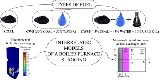
The objectives of this work are as follows: (1) the development of two interrelated mathematical models of slagging in the furnace of a steam boiler with flame combustion of a fuel; (2) study of the effect of combustion parameters for three fuels (coal dust, droplets of CWS and CWSP) on the slagging characteristics of heating surfaces. The developed predictive complex is one of the components of a comprehensive algorithm for assessing the prospects of the practical use of composite fuels instead of solid fossil fuels.

2. Mathematical Modeling

2.1. Slagging of the Boiler Furnace at the Macro-Level

The object of the study was the steam boiler furnace BKZ-210-140F, made in Russia, with following main parameters of superheated steam [30,31,32,33]: Dss = 210 t/h, Pss = 14 MPa, Tss = 560 °C. The inner surfaces of the furnace, with sizes of 7424 mm × 7808 mm × 24,000 mm (Figure 1a), are completely shielded by tubes with a diameter of 60 mm (wall thickness of 5.5 mm) with step of 64 mm. The front and rear walls form a slope of a cold funnel in the lower part of the furnace. At the top of the furnace, the rear wall forms aerodynamic protrusion (Figure 1a). The platen superheater is located above the aerodynamic protrusion inside the furnace space. The furnace is equipped with four direct-flow burners with five secondary air channels and four primary air channels alternating in height (Figure 1b). The burners are located in one tier at the corners of the furnace and are directed tangentially to a conditional circle in the center of the furnace with a diameter of 900 mm (Figure 1c). The fuel and air supply devices are installed in an area with a size of 670 mm × 2270 mm (Figure 1b).
Numerical modeling of the combustion process in the furnace was carried out for the following three fuels:
-
lignite of the Bolshesyrskoye deposit, Kansk-Achinsk coal mine, Krasnoyarsk region, Russian Federation (hereinafter—coal);
-
coal water slurry (hereinafter—CWS), a fuel blend consisting of 50 wt% of coal and 50 wt% of water;
-
coal water slurry with petrochemicals (hereinafter—CWSP), a fuel blend consisting of 45 wt% of coal, 45 wt% of water and 10 wt% of used engine oil.
The thermal characteristics of these fuels are presented in Table 1 [34,35,36]. Within the framework of the developed mathematical model, the water added during the preparation of CWS and CWSP, when fuels are sprayed by nozzles, is modeled as a liquid that is concentrated on the surface of coal particles. The evaporation of this moisture from the surface of coal particles is described by the droplet evaporation model [12]. An oil in the composition of CWSP is described in the mathematical model as a component of volatile substances in the composition of solid fossil fuel.
The fusibility characteristics of the coal ash (Table 2) are taken in accordance with the reference data [35]. The initial deformation temperature, hemispherical temperature and flow temperature were determined in accordance with the procedures described in [37,38,39].
In the boiler BKZ-210-140F, to reduce emissions of nitrogen oxides and reduce furnace slagging, “burner not in operation” technologises were applied. Primary air with fuel is supplied through burners B, C and D (Figure 1c), while secondary air is supplied to all four burners. This creates a lack of oxygen for the burners “in operation”. The flow rate and temperature of primary and secondary air in all calculation options are taken constant. The consumption of each type of fuel was set based on the required steam output of the boiler at an identical load. Boundary conditions for all calculation options are presented in Table 3. The platen superheater (Figure 1a) is modeled by a spatial domain with a volumetric heat absorption of 12.4 MW, according to boiler operating data [31,40].
The sizes of finely dispersed fuel particles were set by the Rosin–Rammler distribution [41]. It was assumed that the fineness of coal or the coal component of CWS and CWSP corresponds to the grinding of solid fuel in fan mills (Table 4). Typical values for the grinding parameters of industrial fan mills have been taken in accordance with the data [30,31]. Numerical modeling was carried out for ten fuel fractions, the size of which was determined automatically by Ansys Fluent computational algorithms. The supply of CWS and CWSP into the furnace simulates the injection of liquid fuel through nozzles installed in the middle of each primary air channel. The spray angle of the nozzles is assumed to be 30°, the speed of the fuel slurry in the narrow section of the nozzle is assumed to be 250 m/s.
Numerical studies were performed using the commercial package Ansys Fluent. The flame of the fuel–air mixture in the furnace was specified in the model as a two-phase turbulent flow system consisting of gas and a solid phase. For a gas, the time-averaged equations of conservation of mass (1), motion (2), and energy (3) were formulated using the Euler approach, considering the interfacial interaction.
( ρ v ) = S m ;
( ρ v v ) = P + τ + S v ;
( ρ v h ) = ( k eff T g i h i J i ) + S h + S hr + S h c r .
For the solid phase, the particle trajectories were calculated using the random wandering model of particles (Lagrangian approach), considering thermophoresis and the lifetime of random vortices [42]. Particles’ combustion of the solid phase in the model is implemented in the form of the following sequence of stages: inert heating, evaporation of moisture, release of volatiles, combustion and combustion of coke residue. Physical and chemical processes and the corresponding numerical submodels built into Ansys Fluent are presented in Table 5 [42].
Accounting for the radiation component of the heat flux is performed under the following conditions: the particle emissivity factor ε = 0.85; the radiation scattering coefficient by particles is assumed to be 0.6; the absorption coefficient of the gaseous medium corresponded to a mixture of “gray” gases.
The kinetic parameters of chemical reactions are presented in the Table 6. The ratio of carbon, hydrogen and oxygen in the volatile matter (first reaction, Table 6) was determined in accordance with the chemical composition of fuel.
Slagging of furnace walls is described by the original mathematical model using the user-defined function in Ansys Fluent. In the function, the probability of an ash particle build-up to the furnace wall depends on its temperature and burnout degree, as well as the ash fusibility characteristics [27]. The incompleteness of fuel combustion (0.5%) was taken as a criterion for particle burnout; i.e., when the degree of burnout is more than 99.5%, the adhesion of a particle to the wall becomes possible, otherwise it is reflected from the wall according to the elastic collision law. For the burnt fuel particles, the probability of sticking to the furnace walls depends on temperature and ash fusibility characteristics, which are presented in Table 2. When developing the mathematical model, a linear increase in the probability of particle build-up was assumed depending on temperature (Table 2): at particle temperature T = TA, the probability of build-up is equal to 0; at particle temperature T = TC the probability is equal to 1 [52].
Building a finite element mesh is an important step for obtaining reliable simulation results. To assess the influence of the grid element sizes on the simulation results, a series of calculations was carried out with a gradual increase in the number of elements. By refining the meshes near the burners, the calculations were carried out for grids consisting of 0.25 × 10⁶, 0.5 × 10⁶ and 1 × 10⁶ elements (Table 7). The grid convergence index (GCI) is calculated according to recommended procedure for estimation of discretization error [53,54]. The number of elements and the characteristic size of the computational grid were considered optimal when the corresponding convergence criteria were met (GCI ≤ 0.05%). Grid 2 satisfies this condition (Table 7).

2.2. Slagging of the Boiler Furnace at the Micro-Level

Figure 2 shows the area for solving the task of the heating surface slagging (on the example of a tube) in the boiler furnace when burning three different fuels (coal, CWS, and CWSP). It was assumed (Figure 2a) that a tube with a diameter of d = 60 mm at the initial time t = 0 is in a heated gaseous medium T = Tg. During fuel combustion (t > 0), a slag layer with a thickness δa gradually forms on the tube surface (Figure 2b). The limiting value of the slag layer thickness was set to 7 mm, because further increase in the layer is limited by the inter-tube distance [55]. The rates of a slag layer formation when burning different fuels were taken from the results of numerical studies via the model described in Section 2.1. Temperature (Ts = 560 °C) and pressure (Ps = 14 MPa) of the steam–water mixture inside the shielding tubes were set according to [35]. The heat transfer coefficient α1 from the steam–water medium to the inner wall of the tube was taken according to [56]. The thermophysical properties of the tube material (steel) corresponded to the data of [35]. The wall thickness δs of the steel tubes was 5.5 mm. The ash thermophysical properties were taken according to the data of [57]; the thermophysical properties of the air corresponded to the data of [58]. The heat transfer coefficient α2 from the flue gases to the outer wall of the shielding tubes and the flue gases’ emissivity factor were taken according to the recommendations [35]. Heat transfer through the heat exchange surface was considered in a planar formulation (for an infinite plate), since the ratio of the outer and inner diameters of the tube is less than 1.8 [56].
The solution area of the formulated task included the following three zones (Figure 2b): steel, slag and flue gases. The total size of the entire system L was 10 mm. The complexity of solving the formulated task consisted in the dynamic change in the slag layer thickness over time (the position of a border between ash layer and heated flue gases shifted).
The processes of heat and mass transfer in the region of solving the task of slagging tubes in the boiler furnace (Figure 2) are described by a system of partial differential equations written in the Cartesian coordinate system. The mathematical model is formulated in a one-dimensional formulation due to the uniformity of heat supply to the tube surface.
The algorithm for solving the formulated problem assumed the implementation of several computational schemes. Each of the schemes was determined by the geometry of the solution area corresponding to the different stages of the slagging of the pipe surface over time (Figure 2). Within each step mentioned below, the coordinates of the different regions’ boundaries of the steel tube wall/ash layer/heated flue gases system were numbered from the origin of coordinates in the direction of the solution area outer boundary (x = L).
First stage at 0 < tt1 (Figure 2a).
Heat equation for tube wall (0 < x < x1):
ρ 1 C 1 T 1 t = λ 1 2 T 1 x 2 .
Heat equation for heated flue gases (x1 < x < L):
ρ 3 C 3 T 3 t = λ 3 2 T 3 x 2 .
Initial conditions:
T1 = T0; T3 = Tg.
Boundary conditions:
x = 0 :   λ 1 T 1 x = α 1 ( T s T ) ,     t > 0 , α 1 > 0 ;
x = x 1 :   λ 1 T 1 x = λ 3 T 3 x + α 2 ( T s T ) + ε σ ( T s 4 T 4 ) ,     t > 0 , α 2 > 0 ;
x = L :   T x = 0 .
Second stage at t1 < tt* (Figure 2b).
Heat equation for tube wall (0 < x < x1):
ρ 1 C 1 T 1 t = λ 1 2 T 1 x 2 .
Heat equation for slag layer (x1 < x < x2):
ρ 2 C 2 T 2 t = λ 2 2 T 2 x 2 .
Heat equation for heated flue gases (x2 < x < L):
ρ 3 C 3 T 3 t = λ 3 2 T 3 x 2 .
The initial conditions correspond to the end conditions of the previous stage. Boundary conditions:
x = 0 :   λ 1 T 1 x = α 1 ( T s T ) , t > 0 , α 1 > 0 ;
x = x 1 :   λ 1 T 1 x = λ 2 T 2 x , T 1 = T 2 ;
x = x 2 :   λ 2 T 2 x = λ 3 T 3 x + α 2 ( T s T ) + ε σ ( T s 4 T 4 ) , t > 0 , α 2 > 0 ;
x = L :   T x = 0 .
To solve a system of non-linear transient partial differential equations with appropriate initial and non-linear boundary conditions, an algorithm has been developed based on the group of numerical methods: finite differences, locally one-dimensional and iterative and sweep methods using a four-point implicit difference scheme. The solution algorithm assumed a sequential check at each time step of the conditions, corresponding to the implementation of each of the calculation process main stages.
Verification of the developed mathematical model (4)–(16) and numerical solution algorithm is performed by checking the difference scheme conservative. The error of fulfilling the heat conversation law in the region of solving the heat transfer task (Figure 2) was calculated at each time step. When varying in a fairly wide range of step values along the spatial coordinate (Δx = 10–100 µm) and time step (Δt = 0.001–10 ms), a relatively small error was found in performing the energy balance (the integral value did not exceed 2.5%) in the considered system (Figure 2); additionally, low computational costs for determining the characteristics of heat transfer through the heat exchanger slagged surface is achieved at steps Δx = 25 µm and Δt = 1 ms.
Numerical modeling of the heat transfer process under the conditions of shielding tubes’ slagging during the combustion of various fuels was performed for a steel pipe/ash layer/heated flue gases system (Figure 2), with the thermophysical properties of substances and materials given in Table 8. The size of the task solution region L = 10 mm; tube wall thickness δs = 5.5 mm; initial wall temperature T0 = 293 K; flue gas temperature Tg = 1200–1500 K; heat transfer coefficient from the steam–water medium to the inner wall of the tube α1 = 2·105 W/(m2·K); heat transfer coefficient from flue gases to the outer wall of the tube α2 = 50 W/(m2·K); flue gas emissivity factor ε = 0.8; Stefan–Boltzmann constant σ = 5.67·10−8 W/(m2·K4); according to the results of calculating the characteristics of the boiler furnace slagging, obtained within the framework of the Ansys Fluent macro model (Table 9). The mass rate of the slag layer formation during fuel combustion follows: coal—wm = 38.061·10−3 kg/(m2·s); CWS—wm = 3.255·10−3 kg/(m2·s); CWSP—wm = 3.101·10−3 kg/(m2·s).

3. Results and Discussion

3.1. Boiler Furnace Slagging

Figure 3, Figure 4, Figure 5, Figure 6, Figure 7 and Figure 8 illustrate typical temperature fields in a boiler furnace and typical fields of slagging rates of furnace walls for the three fuels being burned. Table 9 presents the average growth rate of slag deposits on the furnace walls and the conversion degree of the fuel coke residue.
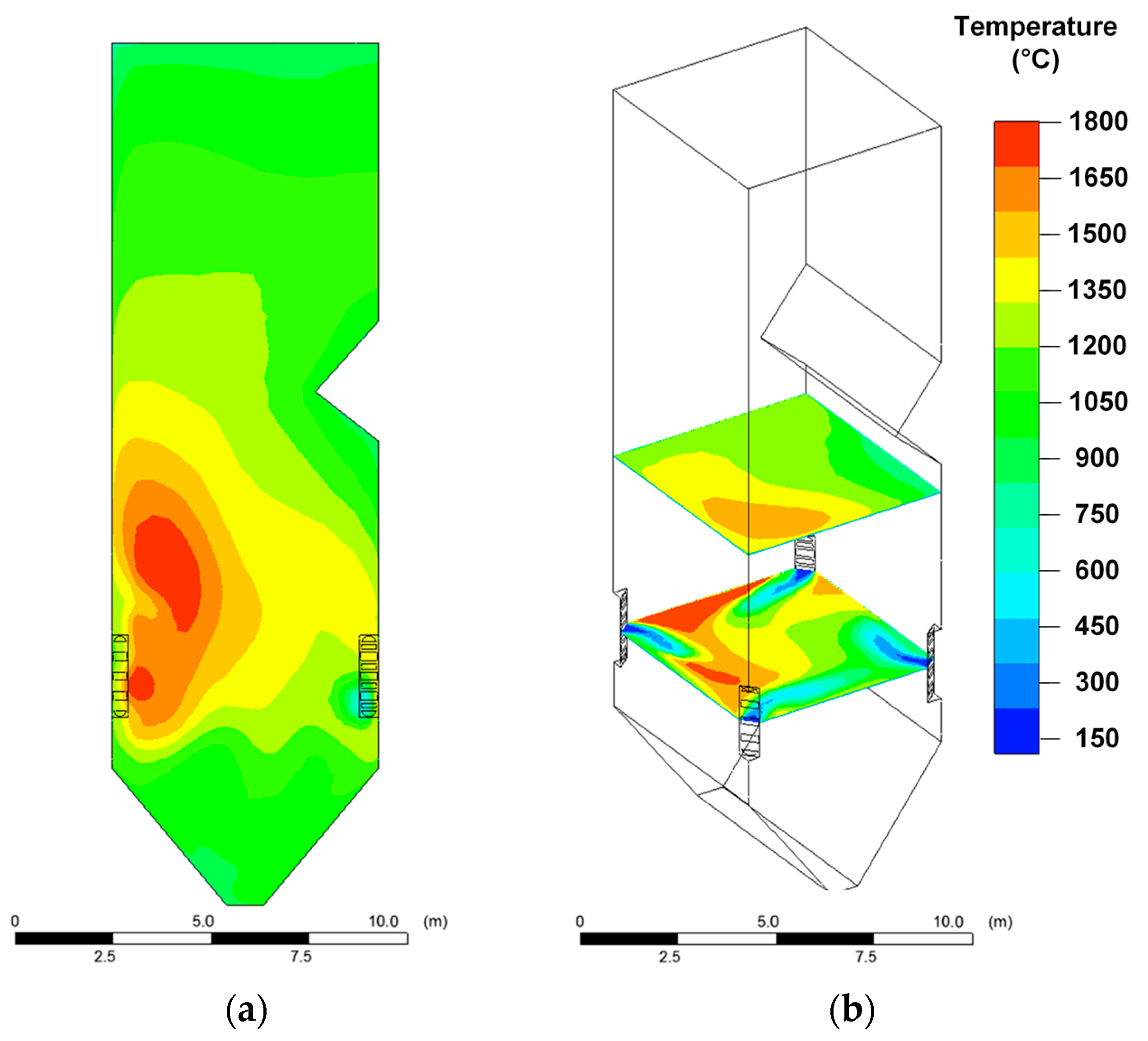
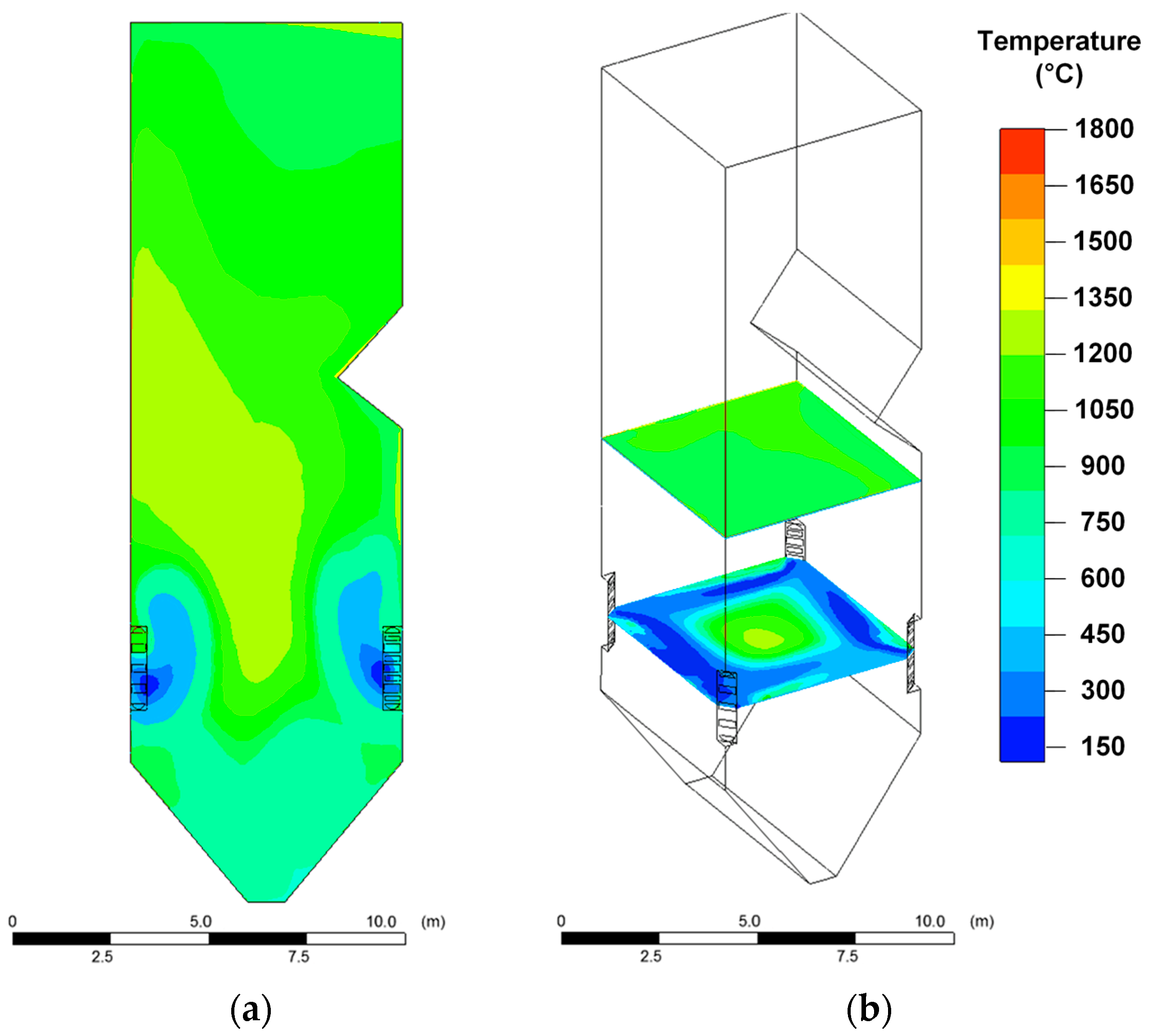
Relatively high temperatures in the boiler furnace are achieved when dry coal dust is burned (Figure 3). In this case, in different areas of the furnace, the temperature varied in the widest range of 300–1800 °C (
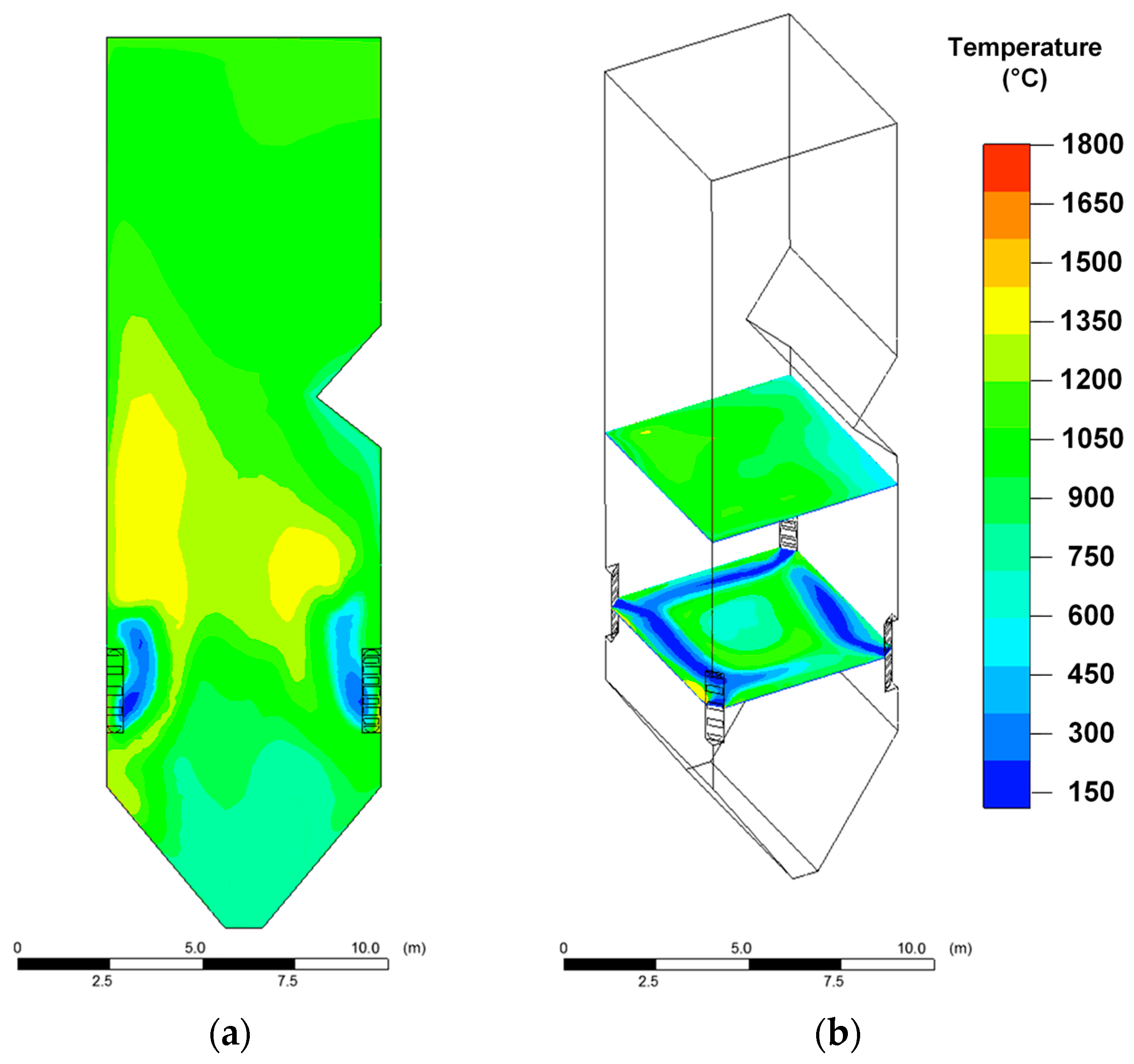
Figure 3) compared with other fuels (CWS and CWSP). When CWS is burned, the temperature varied from 200 °C to 1200 °C (Figure 4); when CWSP is burned, from 200 °C to 1350 °C (Figure 5). At the same time, the flue gas temperatures in the upper part of the furnace near the platen superheaters had fairly close values (1000–1050 °C) for all three fuels under consideration (Figure 3, Figure 4 and Figure 5).
When CWS and CWSP are burned, the relatively low temperature zones (200–600 °C) near the fuel burners are much wider than when coal dust is burned. This is especially noticeable when analyzing the temperature distribution in the cross section of the furnace (Figure 4 and Figure 5). The result is due to the relatively high moisture content in the composition fuel slurries. When injected into the furnace, a droplet of a slurry, in contrast to a particle of dry coal, undergoes a relatively long evaporation stage, accompanied by thermal energy consumption and, as a consequence, a decrease in the gas temperature. This suggests that particles of softened ash falling into these zones will harden, i.e., the intensity of formation of the slag layer on the furnace heating surfaces and on the burners themselves may be less than when burning coal dust.
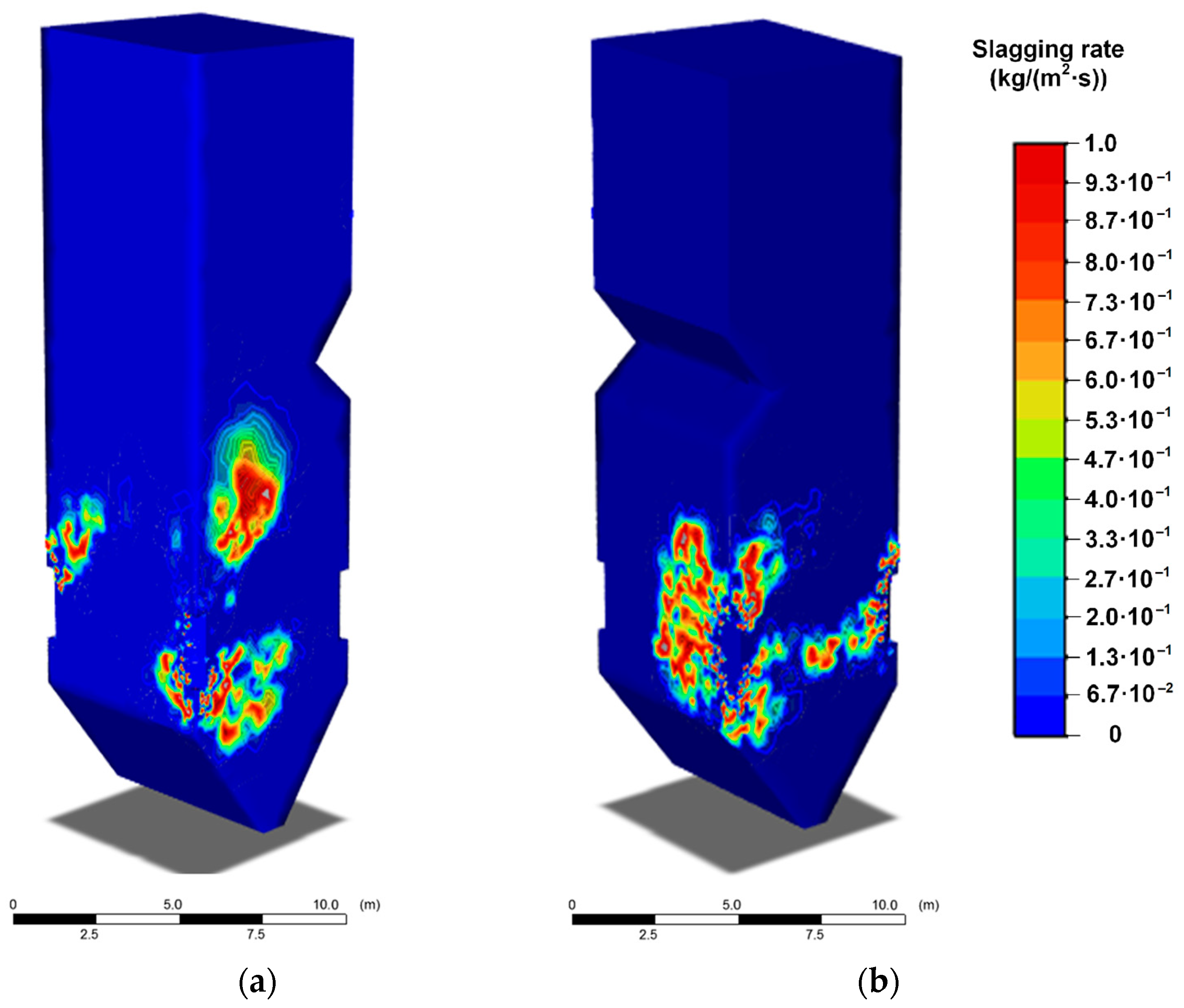
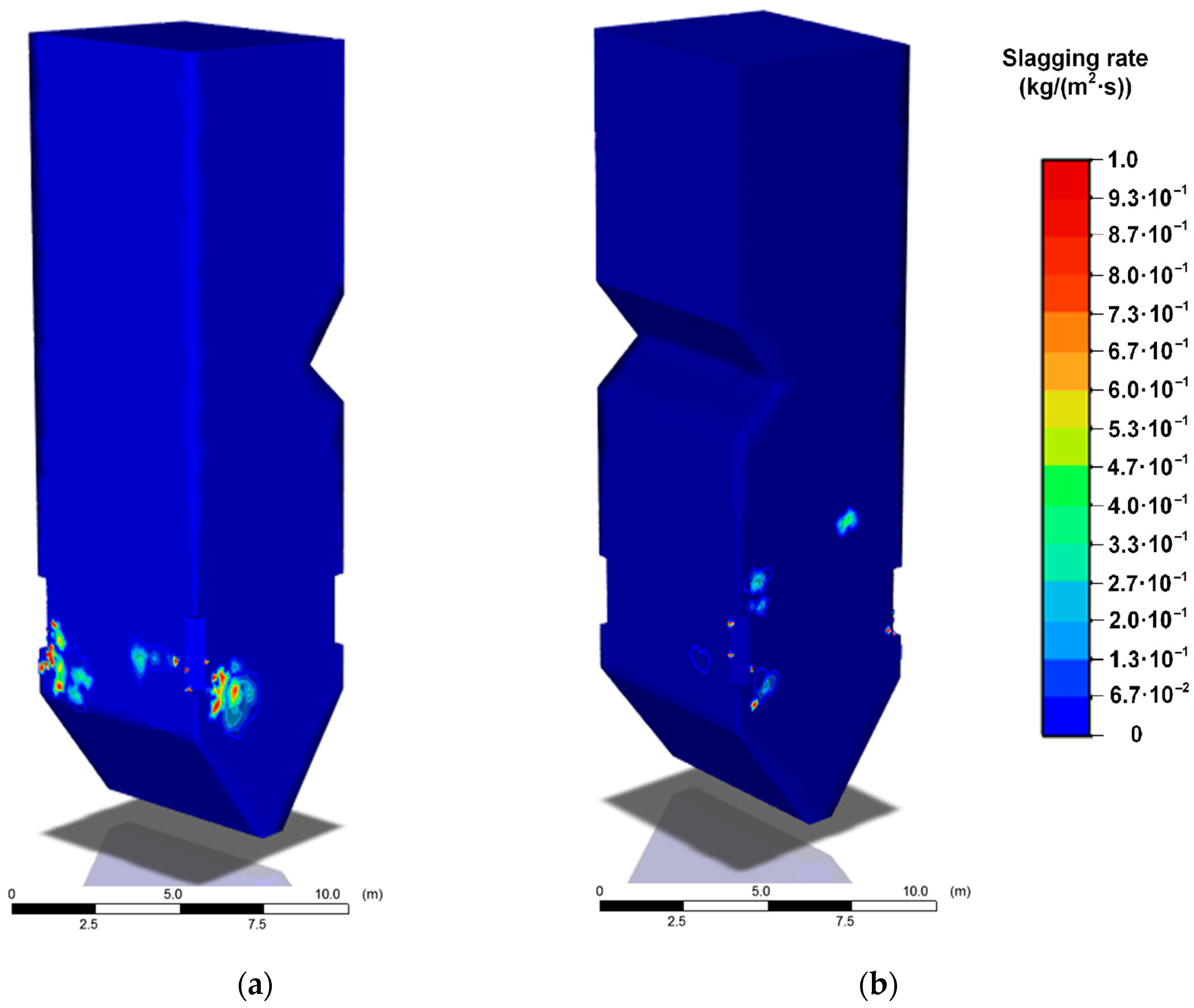
The temperature distribution inside the boiler furnace is one of the factors that determine the slagging intensity of heating surfaces. As can be seen from Figure 6, Figure 7 and Figure 8, the areas of high slagging rates are the most extensive in the case of coal dust combustion (
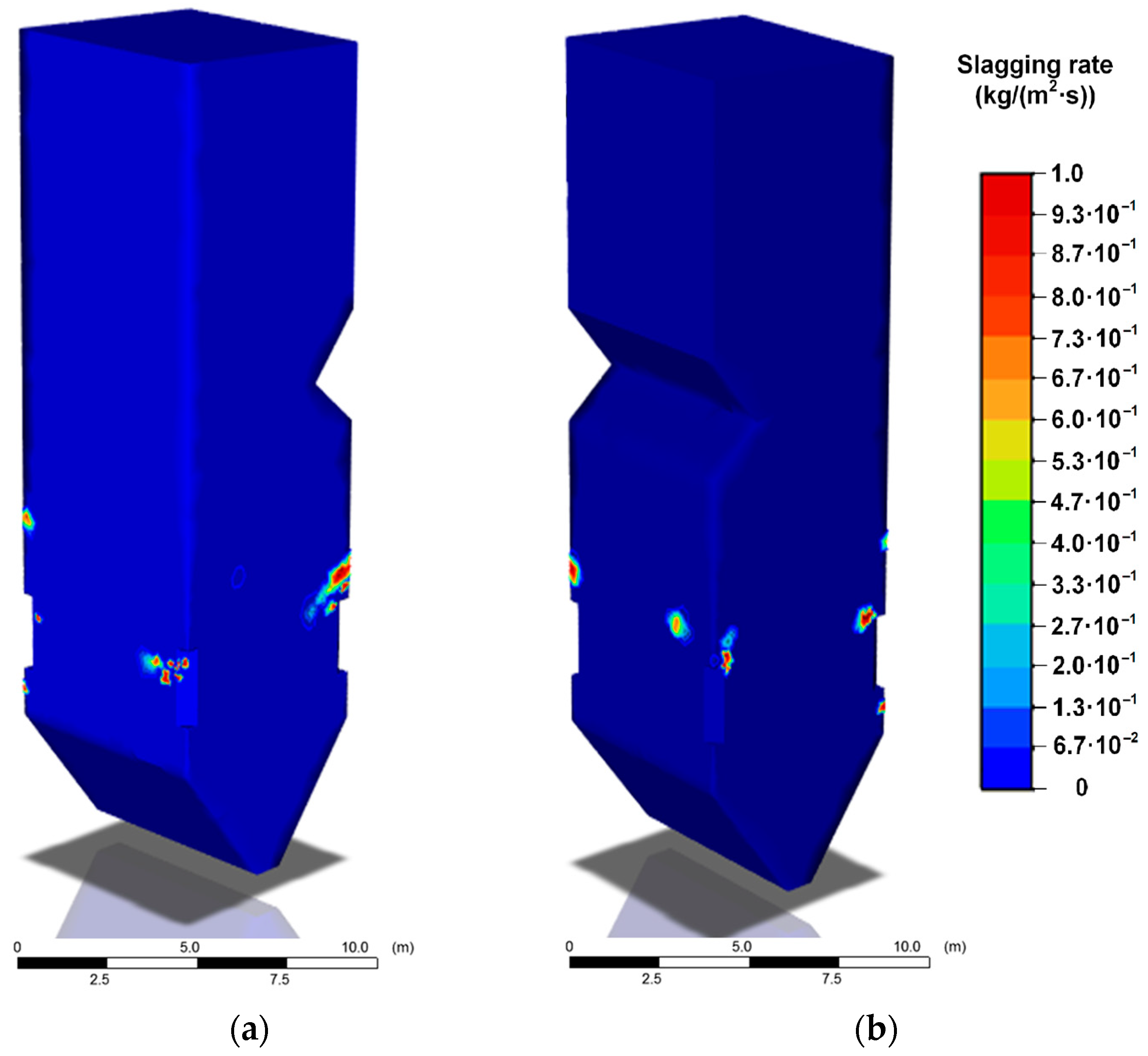
Figure 6). These areas are concentrated in the lower and middle parts of the furnace in the radiation heat exchange zone. It is during the coal dust combustion that the temperatures of the gases are significantly higher than the softening temperature of the ash (1120 °C). When CWS and CWSP are burned, the well-defined areas of slagging (Figure 7 and Figure 8) are characterized by lower rates of this process. In addition, the zones of slag formation are localized on small areas of heating surfaces. Table 9 provides the average growth rates of slag deposits on the furnace walls for different fuels being burned.
As can be seen from the above results, coal combustion provides the highest peak temperatures in the boiler and the most complete fuel burnout. However, in this case, the slagging rate will be maximum. The use of CWS instead of coal makes it possible to reduce the average rate of slagging of furnace surfaces by almost 12 times. However, combustion of CWS is characterized by rather low temperatures in the furnace and a low degree of burnout compared with pulverized coal, due to a significant proportion of water in the composition. To improve the energy characteristics of CWS, including the combustion temperature and completeness of burnout, additives of liquid combustible organic components are used.
As the simulation results show, in addition to an increase in peak temperatures in the furnace by 13–38%, the average rate of slag deposit growth decreases by 5% when burning CWS compared to CWSP. The latter result is explained by the difference in the component composition of these fuels. CWSP contains fewer components that form ash residue during combustion.

3.2. Heat Transfer through the Tube Wall of the Heat Exchanger When Slagging

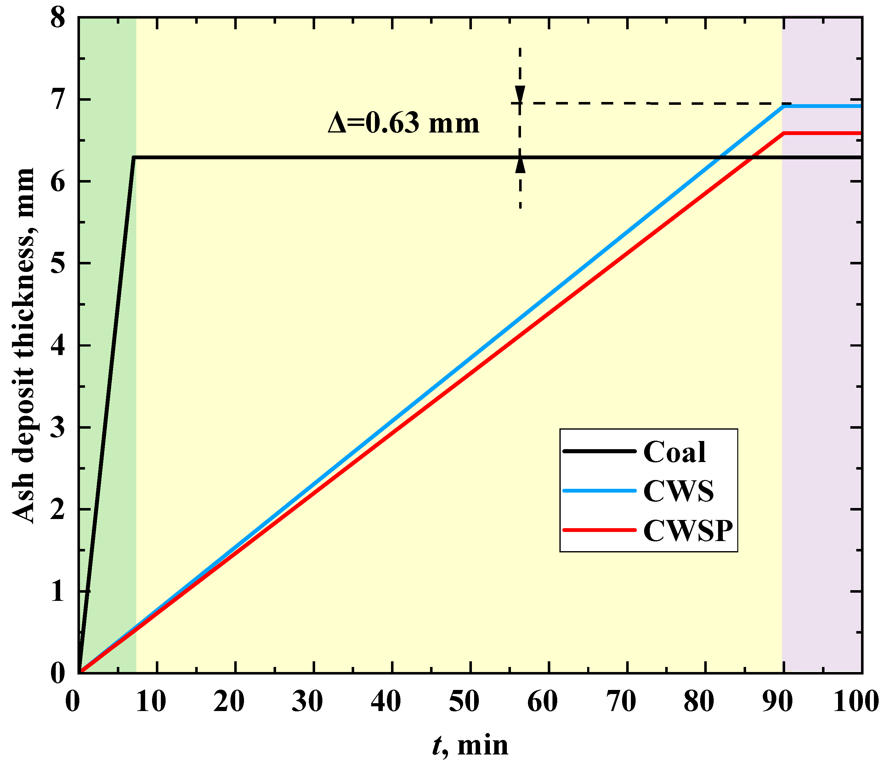
Figure 9 illustrates the change in the thickness of a slag layer on the surface of the heat exchanger tube during combustion of different fuels. When burning coal, the limiting value of the ash deposit thickness of 6.3 mm is reached in 7 min (areas in the boiler furnace subject to the most intense slagging, see Figure 6). When CWS and CWSP are burned, the formation of an ash layer in similar areas (Figure 7 and Figure 8) occurs at a slower rate (a possible maximum is reached in 90 min). When burning coal, the growth rate of the slag layer thickness is 0.90 mm/min. When burning CWS and CWSP, this parameter is 0.077 mm/min and 0.072 mm/min, respectively.
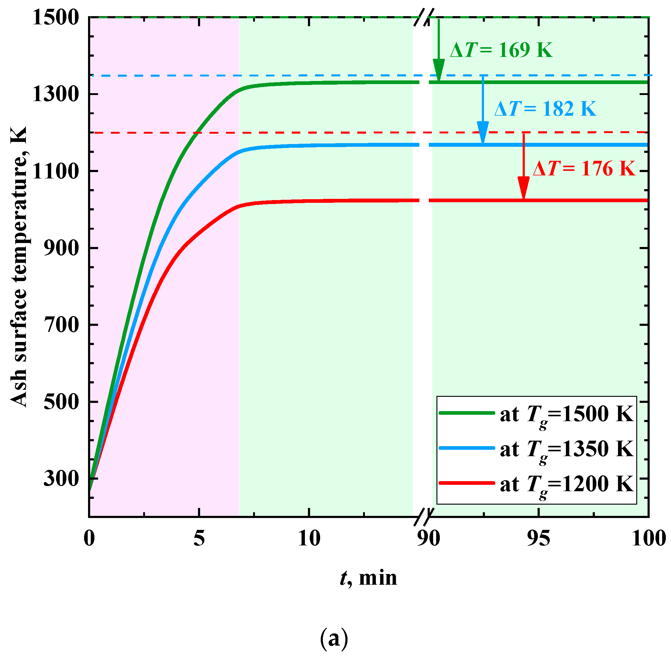
Figure 10 shows the trends in the surface temperature of the slag layer at different temperatures of the combustion products. An intense temperature increase is most typical at the stages of formation and growth of a slag layer (Figure 10) on the heat exchanger surface. A constant surface temperature is reached after the completion of the slag layer formation. The time delay (about 6 min) between the moments of stabilization of the surface temperature and the thickness of the slag layer is because the thermal conductivity of the latter increases with an increase in the degree of ash sintering under the heating by flue gas [59,60].
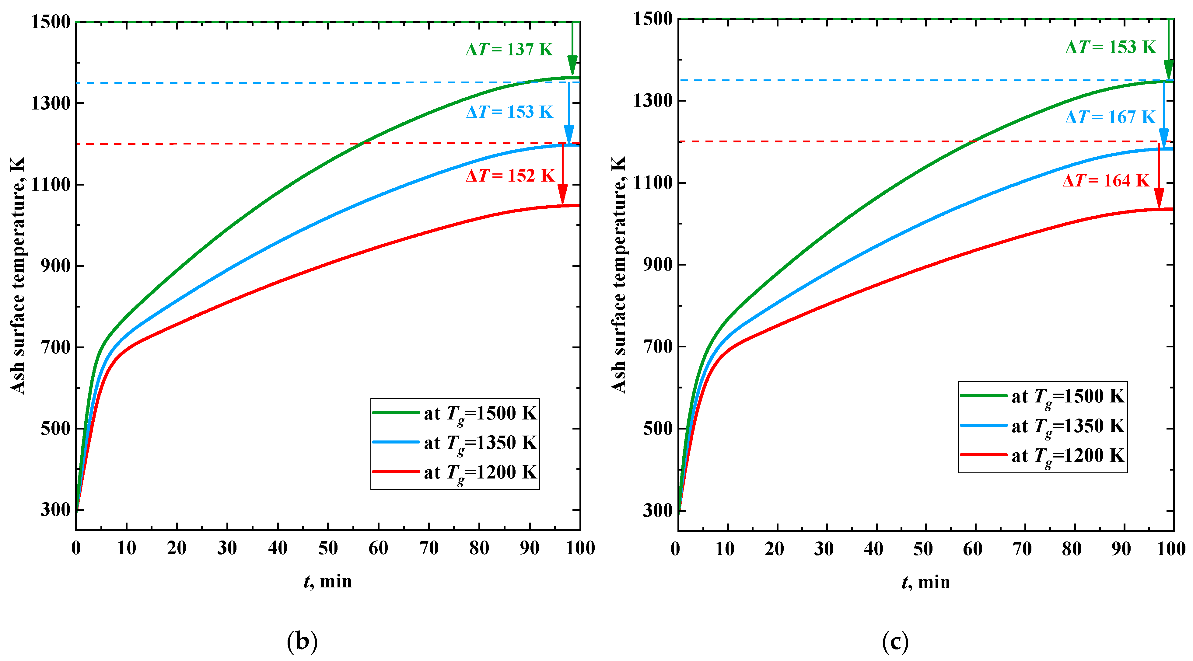
When burning coal, the calculated rate of increase in the slag surface temperature was about 140 K/min (Figure 10a). During the combustion of CWS and CWSP (Figure 10b,c), the increase in the surface temperature of the ash layer was non-monotonic. At the beginning of the process, the average temperature growth rate was about 70 K/min. After 5–7 min and until the values stabilized, the average rate of temperature increase in the ash layer was about 5 K/min. In this case, the higher the temperature of the surrounding gas, the higher the intensity of heating of the ash layer surface.
After stabilization of the thickness of the ash layer, the temperature of its surface no longer reaches the temperature of the surrounding high-temperature gases. Temperature losses during slagging of heating surfaces are 13–17% when coal is burned, 10–15% when CWS is burned, and 11–16% when CWSP is burned. Thus, the maximum difference between the temperature of the gases and the surface of the ash layer can be expected during the combustion of coal dust. For slurry fuels, this difference is expressed to a lesser extent. The results obtained suggest that, in terms of the ash layer thermal diffusivity, the combustion of CWS or CWSP is more efficient than coal combustion.
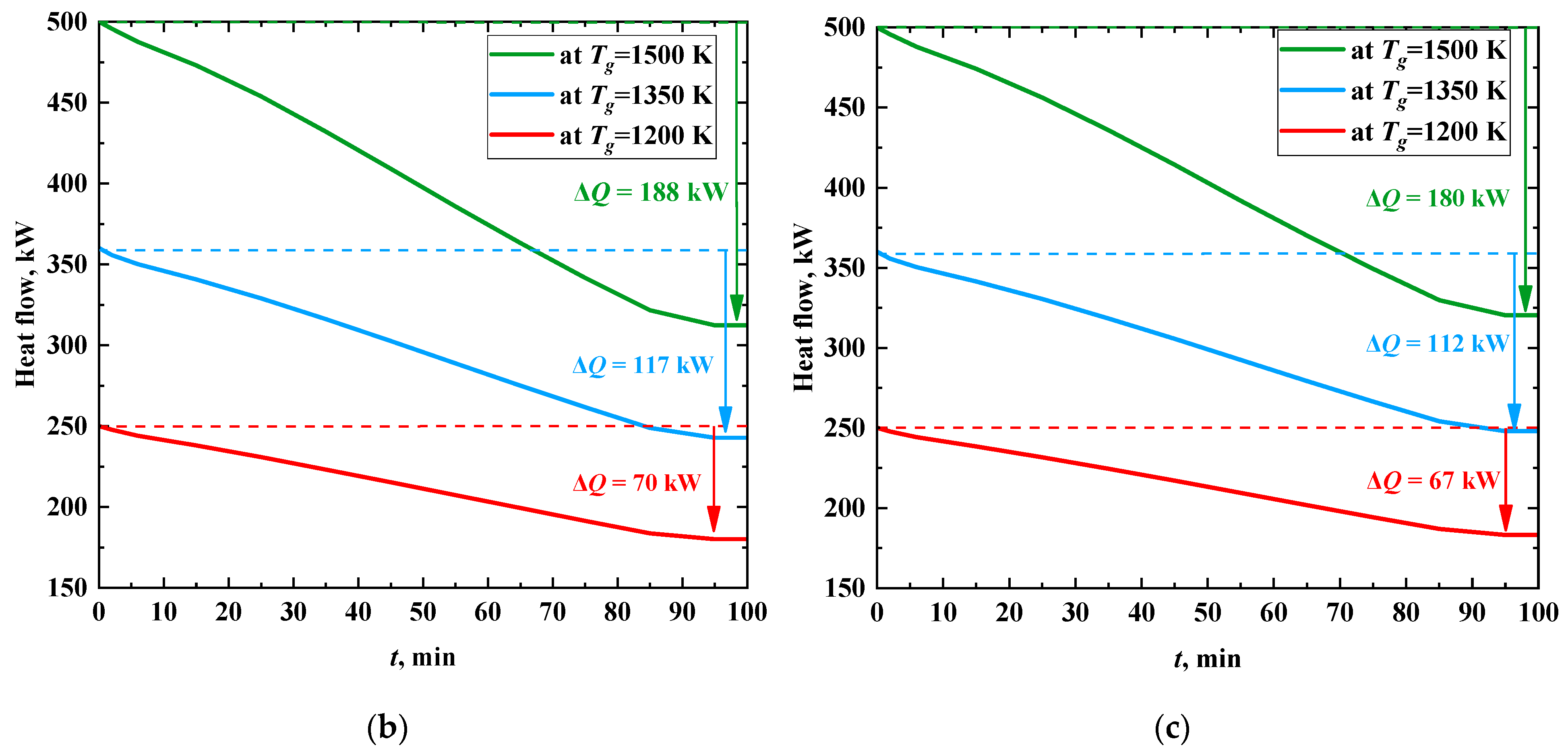
Figure 11 shows the time change of the heat flux to a heat transfer fluid when burning different fuels at several temperatures of the gases. As the thickness of the ash layer increases, the heat flux decreases significantly and stabilizes after the formation of the layer, similarly to the ash surface temperature. The heat flow is reduced due to insulation of heat exchanger tubes during their slagging by 33–50% when coal is burned, and by 39–60% and 35–55%, when CWS and CWSP are burned, respectively. The intensity of heat flux decrease is at its maximum in the first 7 min of the process. When coal dust is burned (Figure 11a), the values of this parameter vary from 9.14 to 24.57 kW/min. Further, the value of the heat flux takes a steady value and does not change (Figure 11a). If CWS or CWSP are burned (Figure 11b,c), the decrease in heat flux is much slower (0.67–1.87 kW/min).
The considered composite fuels contain one common component: lignite with the ash deformation temperature of 1120 °C. However, the presence of a large proportion of moisture in lignite based CWS and CWSP leads to strong differences in the temperature field in the boiler furnace when such fuel slurries are burned, compared with dry coal. Therefore, the tendencies to slagging when replacing coal with CWS and CWSP will differ. Flame temperatures during coal combustion can reach 1800 °C, while during combustion of CWS and CWSP, the maximum temperature in the furnace did not exceed 1200 °C and 1350 °C, respectively. When burning coal dust, the zones of intense slagging are predominantly located along the line of burners, as well as above and below it. When CWS and CWSP are burned, the areas of intense slagging are many times smaller. The average growth rate of the slag layer during coal combustion is almost 12 times higher than when slurries are burned. Modeling the dynamics of the formation of ash layer and its temperature characteristics showed that when coal dust is burned, negative processes proceed at a faster rate.
When burning CWS and CWSP, an ash layer of critical thickness is formed almost 13 times slower than when dry coal dust is burned. Even though the heat flux through the heat exchanger wall is at its maximum during coal combustion, in this case it is possible to predict a greater decrease in heat transfer with an increase in slag layer thickness. The results of numerical simulation showed that the difference between the temperature of the gases and the surface of the ash layer in the case of CWS and CWSP combustion is 3–5% less than in the case of coal combustion. Thus, it can be assumed that when burning slurries, the risks associated with the effect of slagging on the efficiency and functionality of a boiler will be less than when burning coal dust. Since slurries are less harmful with respect to slagging, smaller furnaces can be used for their combustion than for coal combustion (in this case, the issue of the efficiency of burning slurry droplets in small furnaces requires a separate study). The data obtained in this work can be used to develop technologies for controlling and preventing slagging, in particular, for adjusting the temperature regime, the boiler load, the frequency of cleaning and the placement of blowers. The developed algorithm is quite universal and is a concept for a comprehensive study of the characteristics of the boiler furnace slagging at different discretization levels. To ensure the reliability of the forecast results for specific boiler furnaces and fuels, it is necessary to perform new calculations. Each such calculation is moderately time consuming and can be performed in a relatively short time on a modern PC. In the future, the presented algorithm may become the basis of a commercial product that will be applicable for solving the problems of predicting the characteristics of slagging and setting up systems for automated cleaning of heating surfaces.

4. Conclusions

Mathematical models were developed to describe slagging in the furnace of a steam boiler with flame combustion of coal dust and promising slurry fuels (CWS and CWSP). The results of numerical simulation showed that the combustion of CWS and CWSP instead of dry coal dust is characterized by a temperature decrease in the boiler furnace by 450–600 °C. Calculations showed that the completeness of solid particle burnout during CWS combustion is minimal, and amounts to 94.5%. When burning CWSP, this characteristic corresponds to the burnout degree of dry coal particles (about 97%).
The combustion of CWSP, in comparison with CWS, is characterized by higher temperatures in the boiler furnace (higher by 13–38%), a lower average growth rate of the ash layer (lower by 5%) and lower losses of a heat flux (lower by 2%) from flue gases to a heat transfer fluid. In the context of slagging impact, replacing coal with slurry fuel is likely to improve the stability and reliability of a boiler operation, due to a lower slagging rate and the smaller areas subject to this process.

Author Contributions

Conceptualization, K.V.; data curation, K.P.; formal analysis, O.V.; investigation, K.V.; funding acquisition, K.V.; software, K.P.; project administration, O.V.; supervision, D.G.; writing—original draft, K.V.; writing—review and editing, D.G. All authors have read and agreed to the published version of the manuscript.

Funding

This research was supported by the Russian Science Foundation [grant number 22-23-00040, https://rscf.ru/project/22-23-00040/ (accessed on 25 December 2022)].

Institutional Review Board Statement

Not applicable.

Informed Consent Statement

Not applicable.

Data Availability Statement

Data available within the article.

Conflicts of Interest

The authors declare no conflict of interest.

Abbreviations

Abbreviations
CFDcomputational fluid dynamics
CWScoal water slurry
CWSPcoal water slurry with petrochemicals
DTGdifferential thermogravimetric analysis
Nomenclature
Adash (%)
Cheat capacity (J/(m3·K))
Cdaf, Hdaf, Ndaf, Odaf, Sdaffraction of carbon, hydrogen, nitrogen, oxygen and sulfur in the coal converted to a dry ash-free state (%)
Dssfuel consumption in a boiler (t/h)
dcontact diameter (mm)
dmin, dmax, dmeanminimum, maximum and average dispersion of coal (μm)
Fintegral area (mm2)
henthalpy (J/kg)
Jidiffusion flow of i-th component (kg/(m2∙s))
keffeffective heat transfer coefficient (W/(m∙K))
Lsolution region size (mm)
ngrindability index of fuel (dimensionless parameter)
Ppressure (Pa)
Pssteam-water mixture pressure inside shielding tubes (Pa)
Pssboiler furnace pressure (Pa)
Qas,Vhigher heating value (J/kg)
Δr spatial coordinate step (µm)
Rmaxmaximum weight loss (%/min)
Rminminimal weight loss (%/min)
Sburning index (%2/(min2∙°C3))
Shenthalpy change due to interfacial interaction (W/m3)
Shcrenthalpy change due to chemical reactions (W/m3)
Shrenthalpy change due to radiative heat transfer (W/m3)
Smmass change due to interfacial interaction (kg/(m3∙s))
Sνmoment change due to interfacial interaction (N/m3)
Ttemperature (°C)
TAinitial deformation temperature (°C)
Taheated air temperature (°C)
TBhemispherical temperature (°C)
Tbburnout temperature (°C)
TCflow temperature (°C)
Tggas temperature (K)
Tiignition temperature (°C)
Tssteam-water mixture temperature inside shielding tubes (°C)
Tssboiler furnace temperature (°C)
ttime (s)
Δttime increment (s)
TAtemperature of ash deformation initiation (°C)
TBmolten ash hemisphere formation temperature (°C)
TCmolten ash flow temperature (°C)
tdignition delay time (s)
νvelocity (m/s)
Vvolume (µL)
Vaair flow velocity (m/s)
Vdafvolatile content (%)
Vpfuel particle velocity (m/s)
wlinear growth rate of a slag layer (m/s)
Wahumidity (%)
wmmass rate of ash formation during fuel combustion (kg/(m2·s))
xspatial coordinate (µm)
Δx coordinate increment (µm)
Greek symbol
αheat transfer coefficient (W/(m2·K))
δathickness of a slag layer on the tube surface (mm)
δstube wall thickness (mm)
εemissivity factor (dimensionless parameter)
θcontact angle (°)
λthermal conductivity coefficient (W/(m·K))
ρdensity (kg/m3)
τstress tensor (Pa)
σthe Stefan–Boltzmann constant (W/(m2·K4))

References

  1. Zhang, K.; Hou, Y.; Ye, Z.; Wang, T.; Zhang, X.; Wang, C. Interactions of Coal Pitch with Amphoteric Polycarboxylate Dispersant in Coal Pitch–Water Slurry: Experiments and Simulations. Fuel 2022, 318, 123608. [Google Scholar] [CrossRef]
  2. Du, L.; Zhang, G.; Hu, S.; Luo, J.; Zhang, W.; Zhang, C.; Li, J.; Zhu, J. Upgrade of Low Rank Coal by Using Emulsified Asphalt and Its Application for Preparation of Coal Water Slurry with High Concentration. J. Dispers. Sci. Technol. 2021, 1–10. [Google Scholar] [CrossRef]
  3. Zhou, L.; Li, X.; Zhang, R.; Zhou, W.; Jin, J.; Wang, C.; Tian, Y.; Zhang, K. New Method for Utilizing Waste Tire Pyrolysis Residue to Prepare Slurry Fuel: Adsorption and Slurry Characteristics. Powder Technol. 2021, 386, 236–246. [Google Scholar] [CrossRef]
  4. Al-Lwayzy, S.H.; Yusaf, T.; Saleh, K.; Yousif, B. The Influence of Emulsified Water Fuel Containing Fresh Water Microalgae on Diesel Engine Performance, Combustion, Vibration and Emission. Energies 2019, 12, 2546. [Google Scholar] [CrossRef] [Green Version]
  5. Ma, Y.; Huang, R.; Huang, S.; Zhang, Y.; Xu, S.; Wang, Z. Experimental Investigation on the Effect of N-Pentanol Blending on Spray, Ignition and Combustion Characteristics of Waste Cooking Oil Biodiesel. Energy Convers. Manag. 2017, 148, 440–455. [Google Scholar] [CrossRef]
  6. Mohanty, J.K.; Guru, S.R.; Dash, P.; Pradhan, P.K. Fly Ash Management and Condition Monitoring of Ash Pond. Earth Syst. Environ. 2021, 5, 445–457. [Google Scholar] [CrossRef]
  7. Gonzalez-Salazar, M.A.; Kirsten, T.; Prchlik, L. Review of the Operational Flexibility and Emissions of Gas- and Coal-Fired Power Plants in a Future with Growing Renewables. Renew. Sustain. Energy Rev. 2018, 82, 1497–1513. [Google Scholar] [CrossRef]
  8. Guttikunda, S.K.; Jawahar, P. Atmospheric Emissions and Pollution from the Coal-Fired Thermal Power Plants in India. Atmos. Environ. 2014, 92, 449–460. [Google Scholar] [CrossRef]
  9. Feoktistov, D.V.; Glushkov, D.O.; Kuznetsov, G.V.; Orlova, E.G.; Paushkina, K.K. Ignition and Combustion Enhancement of Composite Fuel in Conditions of Droplets Dispersion during Conductive Heating on Steel Surfaces with Different Roughness Parameters. Fuel 2022, 314, 122745. [Google Scholar] [CrossRef]
  10. Glushkov, D.O.; Paushkina, K.K.; Pleshko, A.O.; Vysokomorny, V.S. Characteristics of Micro-Explosive Dispersion of Gel Fuel Particles Ignited in a High-Temperature Air Medium. Fuel 2022, 313, 123024. [Google Scholar] [CrossRef]
  11. Castanet, G.; Antonov, D.V.; Strizhak, P.A.; Sazhin, S.S. Effects of Water Subdroplet Location on the Start of Puffing/Micro-Explosion in Composite Fuel-Water Droplets. Int. J. Heat Mass Transf. 2022, 186, 122466. [Google Scholar] [CrossRef]
  12. Fedorenko, R.M.; Antonov, D.V.; Strizhak, P.A.; Sazhin, S.S. Time Evolution of Composite Fuel/Water Droplet Radii before the Start of Puffing/Micro-Explosion. Int. J. Heat Mass Transf. 2022, 191, 122838. [Google Scholar] [CrossRef]
  13. Rao, D.C.K.; Karmakar, S.; Basu, S. Atomization Characteristics and Instabilities in the Combustion of Multi-Component Fuel Droplets with High Volatility Differential. Sci. Rep. 2017, 7, 8925. [Google Scholar] [CrossRef] [Green Version]
  14. Baranova, M.P.; Kulagina, T.A.; Lebedev, S.V. Combustion of Water and Coal Suspension Fuels of Low-Metamorphized Coals. Chem. Pet. Eng. 2009, 45, 554–557. [Google Scholar] [CrossRef]
  15. Antonov, D.V.; Valiullin, T.R.; Iegorov, R.I.; Strizhak, P.A. Effect of Macroscopic Porosity onto the Ignition of the Waste-Derived Fuel Droplets. Energy 2017, 119, 1152–1158. [Google Scholar] [CrossRef]
  16. Glushkov, D.O.; Kuznetsov, G.V.; Paushkina, K.K. Switching Coal-Fired Thermal Power Plant to Composite Fuel for Recovering Industrial and Municipal Waste: Combustion Characteristics, Emissions, and Economic Effect. Energies 2020, 13, 259. [Google Scholar] [CrossRef] [Green Version]
  17. Bilirgen, H. Slagging in PC Boilers and Developing Mitigation Strategies. Fuel 2014, 115, 618–624. [Google Scholar] [CrossRef]
  18. Park, H.Y.; Lee, J.E.; Kim, H.H.; Park, S.; Baek, S.H.; Ye, I.; Ryu, C. Thermal Resistance by Slagging and Its Relationship with Ash Properties for Six Coal Blends in a Commercial Coal-Fired Boiler. Fuel 2019, 235, 1377–1386. [Google Scholar] [CrossRef]
  19. Shi, Y.; Li, Q.; Wen, J.; Cui, F.; Pang, X.; Jia, J.; Zeng, J.; Wang, J. Soot Blowing Optimization for Frequency in Economizers to Improve Boiler Performance in Coal-Fired Power Plant. Energies 2019, 12, 2901. [Google Scholar] [CrossRef] [Green Version]
  20. Shi, Y.; Li, M.; Wen, J.; Yang, Y.; Cui, F.; Zeng, J. Heat Transfer Efficiency Prediction of Coal-Fired Power Plant Boiler Based on CEEMDAN-NAR Considering Ash Fouling. Energies 2021, 14, 4000. [Google Scholar] [CrossRef]
  21. Lin, X.; Xi, W.; Dai, J.; Wang, C.; Wang, Y. Prediction of Slag Characteristics Based on Artificial Neural Network for Molten Gasification of Hazardous Wastes. Energies 2020, 13, 5115. [Google Scholar] [CrossRef]
  22. Losurdo, M.; Spliethoff, H.; Kiel, J. Ash Deposition Modeling Using a Visco-Elastic Approach. Fuel 2012, 102, 145–155. [Google Scholar] [CrossRef]
  23. Yang, X.; Ingham, D.; Ma, L.; Zhou, H.; Pourkashanian, M. Understanding the Ash Deposition Formation in Zhundong Lignite Combustion through Dynamic CFD Modelling Analysis. Fuel 2017, 194, 533–543. [Google Scholar] [CrossRef]
  24. García Pérez, M.; Vakkilainen, E.; Hyppänen, T. The Contribution of Differently-Sized Ash Particles to the Fouling Trends of a Pilot-Scale Coal-Fired Combustor with an Ash Deposition CFD Model. Fuel 2017, 189, 120–130. [Google Scholar] [CrossRef]
  25. Chernetskiy, M.Y.; Butakov, E.B. Mathematical Model for Predicting the Formation of Ferrous Deposits during Coal Combustion. J. Phys. Conf. Ser. 2020, 1677, 012102. [Google Scholar] [CrossRef]
  26. Chernetskiy, M.Y.; Butakov, E.B.; Kuznetsov, V.A. Calculation on Ash Deposit Formation during Pulverized Coal Combustion in a Large-Scale Laboratory Furnace. Trans. Acad. 2020, 58, 95–106. [Google Scholar] [CrossRef]
  27. Kleinhans, U.; Wieland, C.; Frandsen, F.J.; Spliethoff, H. Ash Formation and Deposition in Coal and Biomass Fired Combustion Systems: Progress and Challenges in the Field of Ash Particle Sticking and Rebound Behavior. Prog. Energy Combust. Sci. 2018, 68, 65–168. [Google Scholar] [CrossRef]
  28. Wei, Y.; Wang, Y.; Guo, Q.; Cao, Y.; Lai, J. Comparative Study on Ash Deposit Mechanism and Characteristics of Eucalyptus Bark and Bagasse-Firing on Boiler Superheater. Int. J. Press. Vessel. Pip. 2022, 196, 104626. [Google Scholar] [CrossRef]
  29. Pronobis, M. The Influence of Biomass Co-Combustion on Boiler Fouling and Efficiency. Fuel 2006, 85, 474–480. [Google Scholar] [CrossRef]
  30. Dik, E.P.; Soboleva, A.N. Slagging Properties of Irsha-Borodino and Berezovo Coals from the Kansk-Achinsk Coal Field. Therm. Eng. 2004, 51, 716–721. [Google Scholar]
  31. Marshak, Y.L.; Pronin, M.S.; Protsaylo, M.Y.; Vasil’yev, V.V. Experimental Combustion of the Berezovskiy Coal in a Semiopen Eddy Furnace with Liquid Slag Removal. Therm. Eng. 1982, 5, 24–28. [Google Scholar]
  32. Osintsev, K.V.; Prikhodko, Y.S.; Dudkin, M.M. The Influence of Burner Design on Efficiency of Electric Power Plant. In Smart Innovation, Systems and Technologies; Springer: Singapore, 2022; Volume 272, pp. 317–325. [Google Scholar]
  33. Kuzmin, V.A.; Zagrai, I.A.; Desiatkov, I.A. Investigation of Emission Characteristics and Temperature of Furnace Gases in BKZ-210-140F Steam Boiler: Milled Peat Combustion and Support Flaming with Natural Gas. Thermophys. Aeromech. 2021, 28, 281–290. [Google Scholar] [CrossRef]
  34. Khzmalyan, D.M.; Kagan, Y.A. Combustion Theory and Furnace Devices; Energiya: Moscow, Russia, 1976. (In Russian) [Google Scholar]
  35. Kagan, G.M. Thermal Calculation of Boilers (Normative Method), 3rd ed.; Revised and Expanded; All-Russia Thermal Engineering Institute: St. Petersburg, Russia, 1998. (In Russian)
  36. Glushkov, D.O.; Matiushenko, A.I.; Nurpeiis, A.E.; Zhuikov, A.V. An Experimental Investigation into the Fuel Oil-Free Start-up of a Coal-Fired Boiler by the Main Solid Fossil Fuel with Additives of Brown Coal, Biomass and Charcoal for Ignition Enhancement. Fuel Process. Technol. 2021, 223, 106986. [Google Scholar] [CrossRef]
  37. GOST 2057-94 (ISO 540-81); Solid Mineral Fuel. Methods for Determination of Ash Fusibility. iTeh Standard: Etobicoke, ON, Canada, 1996; p. 16.
  38. Van Dyk, J.C.; Benson, S.A.; Laumb, M.L.; Waanders, B. Coal and Coal Ash Characteristics to Understand Mineral Transformations and Slag Formation. Fuel 2009, 88, 1057–1063. [Google Scholar] [CrossRef]
  39. Wu, X.; Zhang, Z.; Piao, G.; He, X.; Chen, Y.; Kobayashi, N.; Mori, S.; Itaya, Y. Behavior of Mineral Matters in Chinese Coal Ash Melting during Char-CO2/H2O Gasification Reaction. Energy Fuels 2009, 23, 2420–2428. [Google Scholar] [CrossRef]
  40. Marshak, Y.L.; Kozlov, S.G.; Dik, E.P.; Suchkov, S.I. Slag Formation of Furnace Chamber When Burning Berezovsk Coal. Therm. Eng. 1980, 1, 16–22. [Google Scholar]
  41. Scott, G.S. Application of the Rosin-Rammler Law to the “Missing Sizes” in Screened Coal; U.S. Department of the Interior, Bureau of Mines: Washington, DC, USA, 1943; Volume 3732. [Google Scholar]
  42. Ranade, V.V.; Gupta, D.F. Computational Modeling of Pulverized Coal Fired Boilers; CRC Press: Boca Raton, FL, USA, 2014; ISBN 9781482215359. [Google Scholar]
  43. McAllister, S.; Chen, J.-Y.; Fernandez-Pello, A.C. Chemical Kinetics. In Fundamentals of Combustion Processes; Springer: New York, NY, USA, 2011; pp. 49–73. [Google Scholar]
  44. Xie, J.; Zhong, W.; Jin, B.; Shao, Y.; Huang, Y. Eulerian–Lagrangian Method for Three-Dimensional Simulation of Fluidized Bed Coal Gasification. Adv. Powder Technol. 2013, 24, 382–392. [Google Scholar] [CrossRef]
  45. Arena, U. Process and Technological Aspects of Municipal Solid Waste Gasification. A Review. Waste Manag. 2012, 32, 625–639. [Google Scholar] [CrossRef]
  46. Salomatov, V.V.; Kuznetsov, G.V.; Syrodoy, S.V. Influence of the Degree of Coal Metamorphism on Characteristics and Conditions of Ignition of Coal-Water Fuel Drops. Thermophys. Aeromech. 2018, 25, 773–788. [Google Scholar] [CrossRef]
  47. Zhang, Q.; Dor, L.; Fenigshtein, D.; Yang, W.; Blasiak, W. Gasification of Municipal Solid Waste in the Plasma Gasification Melting Process. Appl. Energy 2012, 90, 106–112. [Google Scholar] [CrossRef]
  48. Donskoy, I.G. Numerical Study on the Efficiency of Biomass and Municipal Waste Fixed-Bed Co-Gasification. E3S Web Conf. 2019, 114, 06006. [Google Scholar] [CrossRef]
  49. Chen, C.J.; Hung, C.I.; Chen, W.H. Numerical Investigation on Performance of Coal Gasification under Various Injection Patterns in an Entrained Flow Gasifier. Appl. Energy 2012, 100, 218–228. [Google Scholar] [CrossRef]
  50. Guan, Y.; Luo, S.; Liu, S.; Xiao, B.; Cai, L. Steam Catalytic Gasification of Municipal Solid Waste for Producing Tar-Free Fuel Gas. Int. J. Hydrogen Energy 2009, 34, 9341–9346. [Google Scholar] [CrossRef]
  51. Wickramaarachchi, W.A.M.K.P.; Narayana, M. Pyrolysis of Single Biomass Particle Using Three-Dimensional Computational Fluid Dynamics Modelling. Renew. Energy 2020, 146, 1153–1165. [Google Scholar] [CrossRef]
  52. Wieland, C.; Kreutzkam, B.; Balan, G.; Spliethoff, H. Evaluation, Comparison and Validation of Deposition Criteria for Numerical Simulation of Slagging. Appl. Energy 2012, 93, 184–192. [Google Scholar] [CrossRef]
  53. Celik, I.B.; Ghia, U.; Roache, P.J.; Freitas, C.J.; Coleman, H.; Raad, P.E. Procedure for Estimation and Reporting of Uncertainty Due to Discretization in CFD Applications. J. Fluids Eng. Trans. ASME 2008, 130, 0780011–0780014. [Google Scholar] [CrossRef]
  54. Fugmann, H.; Schnabel, L.; Frohnapfel, B. Heat Transfer and Pressure Drop Correlations for Laminar Flow in an In-Line and Staggered Array of Circular Cylinders. Numer. Heat Transf. Part A Appl. 2019, 75, 1–20. [Google Scholar] [CrossRef]
  55. Zhou, H.; Zhang, K.; Li, Y.; Zhang, J.; Zhou, M. Simulation of Ash Deposition in Different Furnace Temperature with a 2D Dynamic Mesh Model. J. Energy Inst. 2019, 92, 1743–1756. [Google Scholar] [CrossRef]
  56. Wong, H.Y. Handbook of Essential Formulae and Data on Heat Transfer for Engineers; Longman: London, UK, 1977; ISBN 0582460506. [Google Scholar]
  57. Robinson, A.L.; Buckley, S.G.; Baxter, L.L. Experimental Measurements of the Thermal Conductivity of Ash Deposits: Part 1. Measurement Technique. Energy Fuels 2001, 15, 66–74. [Google Scholar] [CrossRef] [Green Version]
  58. Kuznetsov, G.V.; Sheremet, M.A. Difference Methods for Solving Heat Conduction Problems; TPU: Tomsk, Russia, 2007. (In Russian) [Google Scholar]
  59. Zhou, H.; Zhou, B.; Li, L.; Zhang, H. Investigation of the Influence of the Furnace Temperature on Slagging Deposit Characteristics Using a Digital Image Technique. Energy Fuels 2014, 28, 5756–5765. [Google Scholar] [CrossRef]
  60. Brink, A.; Laurén, T.; Yrjas, P.; Hupa, M.; Friesenbichler, J. Development and Evaluation of a Long-Term Deposit Probe for on-Line Monitoring of Deposit Growth. Fuel Process. Technol. 2007, 88, 1129–1135. [Google Scholar] [CrossRef]
Figure 1. Scheme of the steam boiler furnace BKZ-210-140F (a), burner configuration (b), furnace cross-section (c).
Applsci 13 00434 g001
Figure 2. Area for solving the problem of heat transfer from an energy source to a coolant during the formation of a slag layer on a tube surface: (a) initial moment of time (t = 0); and (b) moment in the process of a slag layer formation (t > 0). Designations: 1—steel tube wall; 2—slag layer; 3—heated flue gases.
Applsci 13 00434 g002
Figure 3. Typical temperature fields in the boiler furnace when burning coal: in the longitudinal section (a); in the cross sections (b).
Applsci 13 00434 g003
Figure 4. Typical temperature fields in the boiler furnace when burning CWS: in the longitudinal section (a); in the cross sections (b).
Applsci 13 00434 g004
Figure 5. Typical temperature fields in the boiler furnace when burning CWSP: in the longitudinal section (a); in the cross sections (b).
Applsci 13 00434 g005
Figure 6. Typical fields of slagging rates of furnace walls when burning coal: from the front side of the furnace (a); from the back side of the furnace (b).
Applsci 13 00434 g006
Figure 7. Typical fields of slagging rates of furnace walls when burning CWS: from the front side of the furnace (a); from the back side of the furnace (b).
Applsci 13 00434 g007
Figure 8. Typical fields of slagging rates of furnace walls when burning CWSP: from the front side of the furnace (a); from the back side of the furnace (b).
Applsci 13 00434 g008
Figure 9. Typical change in the thickness of the slag layer on the surface of the heat exchanger tube when burning different fuels.
Applsci 13 00434 g009
Figure 10. Ash surface temperature trends when burning different fuels: (a) coal, (b) CWS, (c) CWSP.
Applsci 13 00434 g010aApplsci 13 00434 g010b
Figure 11. Time change of heat flux to a water coolant when burning different fuels: (a) coal, (b) CWS, (c) CWSP.
Applsci 13 00434 g011aApplsci 13 00434 g011b
Table 1. Main fuel characteristics.
CoalCWSCWSP
Thermal characteristics
Operating humidity, %20.860.454.36
Operating ash content, %6.23.12.8
Volatile yield, %32.5616.2824.65
High calorific value, MJ/kg21.4110.714.03
Ultimate analysis (for dry ash-free state)
Cdaf, %74.174.177.4
Hdaf, %555.5
Ndaf, %0.90.90.74
Sdaf, %0.30.30.24
Odaf, %19.719.716.12
Thermal characteristics (for dry state)
Density, kg/m312201220 *1220 *
Heat capacity, J/(kg·°C)11301130 *1130 *
*—characteristic values are similar to those of coal, which is the solid fuel base of CWS and CWSP.
Table 2. Fusibility characteristics of coal ash [35].
FuelTA, °CTB, °CTC, °C
Coal112011801200
Table 3. Boundary conditions.
CharacteristicsCoalCWSCWSP
Fuel consumption, kg/s7.30414.60811.140
Fuel temperature, °C1405050
Primary air flow, kg/s11.53
Primary air temperature, °C140
Secondary air flow, kg/s51.35
Secondary air temperature, °C320
Water temperature in the furnace walls, °C350
Emissivity factor of the furnace walls0.8
Steam temperature in ceiling superheater, °C370
Emissivity factor of ceiling superheater0.6
Table 4. Grindability index of fuels.
Characteristicsdmin, μmdmax, μmdmean, μmn
Coal11000750.9
Table 5. Numerical models.
ProcessModel
Turbulencek-ε model
Radiative heat transferModel of discrete ordinates and interaction of particles with radiation
Volatile yieldOne-stage model according to the Arrhenius equation
Homogeneous combustion considering the influence of turbulenceCombination of the kinetic model of combustion of gaseous components with the model of “vortex shedding”
Heterogeneous combustionDiffusion-kinetic model
Table 6. Kinetic parameters of chemical reactions.
ReactionArEr (kJ/(mol·K))Ref.
Homogeneous combustion
Volatile + 1.706O2 = CO2 + 1.543H2O2.1 × 1011202.7[43,44]
H2 + ½O2 = H2O2.1 × 1014129.8[44,45,46]
2CO + O2 = 2CO21.4 × 101396.8[44,45,46]
Heterogeneous combustion
C + O2 = CO22 × 101260.6[45,47,48]
C + ½O2 = CO2 × 101260.6[44,45,48,49]
C + CO2 = 2CO1.3 × 107259[44,45,48,49,50,51]
Table 7. Grid convergence analysis.
ParametersGrid 1Grid 2 (Examined)Grid 3
Number of cells0.25 × 1060.5 × 1061 × 106
Minimum element size, mm705010
Average element size, mm500260130
Slagging rate of coal, g/(m2·s)35.61838.06141.308
GCI (%)0.0820.0460.001
Table 8. Components’ thermophysical properties in the system of steel tube/ash layer/heated flue gases.
Materialλ, W/(m·K)ρ, kg/m3C, J/(m3·K)
Steel467800530
Ash325401040
Flue gases0.09150.2391210
Table 9. Average slagging rates of furnace walls when burning different fuels.
FuelCoalCWSCWSP
Slagging rate, g/(m2·s)38.0613.2553.101
Conversion degree of coke residue of fuel particles, %97.194.597
Disclaimer/Publisher’s Note: The statements, opinions and data contained in all publications are solely those of the individual author(s) and contributor(s) and not of MDPI and/or the editor(s). MDPI and/or the editor(s) disclaim responsibility for any injury to people or property resulting from any ideas, methods, instructions or products referred to in the content.

