Article

Acoustic Properties Comparison of Ti6Al4V Produced by Conventional Method and AM Technology in the Aspect of Ultrasonic Structural Health Monitoring of Adhesive Joints

1
Faculty of Civil and Transport Engineering, Institute of Machines and Motor Vehicles, Poznan University of Technology, 60-965 Poznan, Poland
2
Faculty of Mechanical Engineering, Division of Virtual Engineering, Poznan University of Technology, 60-965 Poznan, Poland
3
Faculty of Mechanical Engineering, Wroclaw University of Science and Technology, 50-371 Wroclaw, Poland
*
Author to whom correspondence should be addressed.
Appl. Sci. 2023, 13(1), 371; https://doi.org/10.3390/app13010371
Submission received: 1 December 2022 / Revised: 19 December 2022 / Accepted: 23 December 2022 / Published: 28 December 2022
(This article belongs to the Special Issue Structural Health Monitoring: Latest Applications and Data Analysis)

Abstract

:
The article presents the results of ultrasonic testing of Ti6Al4V material produced by the conventional method and the laser bed fusion method. Modern manufacturing techniques, such as additive manufacturing, allow the production of parts with complex shapes. It is important to control the condition of such components throughout their lifetime. The purpose of this article was to determine the basic acoustic properties of Ti6Al4V material produced by two different methods—bar drawing and the additive manufacturing method. On this basis, an inspection scheme was developed for adhesive joints, the components of which are made by additive manufacturing technology. The decibel drops in the amplitudes of pulses reflected from the boundary of the adhesive-Ti6Al4V-AM and adhesive-Ti6Al4V joints were determined. The decibel drops for the connection of materials made with additive technology are higher than for the material made in a conventional way. The difference in decibel drop in the amplitudes of the additive manufactured material versus the drawn rod, depending on the ultrasonic head, can be up to 60%. The results of the study provide an important practical guideline for testing adhesive joints of parts made with additive manufacturing technology.

1. Introduction

Modern techniques for the manufacturing process of machine components allow for reducing material consumption [1,2] which leads to a reduction in waste and toxic compounds emitted into the atmosphere [3,4]. In addition to the environmental aspect, it is also important to match the final product as closely as possible in terms of both shape and properties [5]. Therefore, the use of additive manufacturing technology (AM) for the production of machine components has recently gained importance [6].
Research on the application of this technology includes the optimization of final products in terms of the amount of material used (losses associated with the supporting structure), strength, durability as well as the reduction of defects [7,8,9]. One of the materials manufactured with this technology is Ti6Al4V [10]. Ti6Al4V alloy is widely used in the aerospace [11] and medical industries [12] because of the properties of the finished product. The main advantages of this titanium alloy include low weight and high strength, as well as corrosion resistance [13].
Research on titanium alloys is carried out for both material produced by conventional technology and additive manufacturing method (laser bed fusion—LBF). One direction of research is to apply coatings with specific properties or surface treatment to modify the top layer of the alloy [14,15]. This results in better strength or anti-corrosion properties [16]. On the other hand, the influence of the microstructure of the Ti6Al4V alloy material on the micro-milling process was also studied. Four different structures (bimodal, fully equiaxed, fully lamellar and mill annealed) were obtained from different heat treatments, and the microhardness of each was tested. The authors concluded that fully lamellar microstructures allow to lower cutting forces and reduce tool wear [17]. Other studies related to the machining of this alloy were connected to machining process parameters such as cutting speeds, depth of cut, and the use of cooling substances [18,19,20].
Da Costa et al. [21] evaluate the influence of surface roughness, defect size and location on fatigue strength for Ti6Al4V produced by the additive manufacturing method. Based on the study, the surface roughness of the samples has a significant effect on the initiation of surface and subsurface cracks. Similar conclusions were observed in articles [22,23,24] in which a correlation between fatigue cracking of Ti6Al4V material made with additive manufacturing technology and material fracture, surface roughness and residual stresses was shown. Liu et al. [25] investigated the fracture mechanism of Ti6Al4V alloy fabricated using the laser powder bed fusion method and found that due to the LPBF process and fatigue loading, microvoids are formed, which then merge and accelerate the microcracking process.
Another research direction that has not been widely disseminated at present is the evaluation of parts made with additive manufacturing technology using nondestructive testing techniques [26]. Kim et al. [27] investigated the effect of defects and structure in AM 316L steel on the properties of the ultrasonic wave beam, including phase velocity. The authors of this article confirmed that the phase velocity depends on the pore geometry and crystallographic texture. In addition, it was proven that the phase velocity of the ultrasonic wave is sensitive to changes in anisotropic elastic constants. Other studies have evaluated defects in IN 625 alloy [28]. The study used the Phase array technique to detect deep, cylindrical defects in thin-walled components. The results confirmed the ability to detect cylindrical defects less than 1 mm in diameter in components with flat surfaces. It was further found that these techniques are difficult to apply to assess the condition of additively manufactured parts with a curved surface. Lopez et al. [29] have proven that ultrasound studies using a laser beam have fewer limitations than studies using standard techniques with a coupling agent. In addition, the significance of surface roughness on ultrasonic testing results was recognized, as well as the accuracy of laser ultrasonic inspection of additive manufactured components with cylindrical defects [30].
Ultrasonic testing is also used in assessing the condition of components made of Ti6Al4V alloy. The few scientific articles that describe ultrasonic testing of additive technology parts made of Ti6Al4V alloy present the detection of structural defects [31]. The authors presented the possibility of using laser ultrasonic testing to detect internal holes with a diameter of 0.8 mm. Generating an ultrasonic wave using a laser beam has been used for many years and is constantly being improved [32], but this method has some limitations and is mainly used in laboratory conditions. Therefore, the authors decided to use ultrasonic testing with standard heads and a coupling agent to determine the properties of Ti6Al4V alloy made both by additive manufacturing technology and conventional process. This kind of approach can find application in continuous condition monitoring of parts made by additive manufacturing technology from Ti6Al4V alloy.
The main objective of the research presented in this article is to determine the basic acoustic properties of Ti6Al4V material produced by the conventional method (drawn rod) and by additive manufacturing technology. The comparison of these properties will form the basis for the study of joints that have been made using just this type of material. A novelty included in this article is the evaluation of the condition of adhesive joints of additively manufactured materials using the ultrasonic echo technique. The results of ultrasonic testing provide the basis for developing a new algorithm for evaluation of adhesive joints made with additive manufacturing technology. The new algorithm for evaluating the condition of adhesive joints can also be applied to continuously monitor the condition of the joint (structural health monitoring) and detect defects occurring at the boundary of the adhesive surface of a component made with additive manufacturing technology. A measure of the quality of the adhesive joint, which is the decibel drop between the amplitude of the first two pulses reflected from the boundary of the adhesive–substrate interface, was determined. This was possible due to the previous determination of the basic parameters of the ultrasonic longitudinal wave propagating in the material itself. The results of the study have an important practical aspect. According to the methodology proposed in the article, the evaluation of adhesive joints of materials made with different technologies can be conducted.

2. Ultrasonic Testing of Materials

Modern machines and vehicles increasingly use components made of titanium. Therefore, the research was conducted on the material Ti6Al4V, both made by additive manufacturing technology (Ti6Al4V-AM bars manufactured by laser bed fusion (LPBF) method) and conventionally (drawn rod—Ti6Al4V). Both materials made with different technologies had similar densities. The density for the material made with additive manufacturing technology equals 4.43 g/cm3, and the density for the material made with conventional methods was 4.40 g/cm3.
LPBF-made Ti6Al4V bars were manufactured using an SLM 280 2.0 machine (SLM Solutions Group AG, Lübeck, Germany) and SLM Solutions Ti6Al4V ELI (Grade 23) powder with a powder size distribution of 20–63 µm. Bars were printed vertically using process parameters provided by the powder and machine supplier, i.e., layer height of 60 µm, laser power of 350 W, scanning speed of 1100 mm/s, hatch distance of 0.12 mm, and stripe length of 10 µm. LPBF-made Ti6Al4V bars were tested in as-built conditions.
A rod with a diameter of 25 mm and three different thicknesses (10, 25 and 40 mm) was used. This diameter was selected taking into account the ultrasonic heads used in the laboratory and industrial conditions—the possibility of generating a beam of ultrasonic wave in the tested material. Heads with frequencies from 2 to 20 MHz and a maximum transducer diameter of 12 mm were selected. The basic parameters of the ultrasonic heads used in the study, as well as the selected values of the propagating wave beam in the material, are summarized in Table 1 and Table 2. The diameter of the ultrasonic wave beam for the selected heads was determined based on the relationship:
B = 2 s t g ( a r c sin ( k c f 0.97 D ) )
where:
  • B—beam diameter mm,
  • s—distance from the ultrasonic transducer mm,
  • k—coefficient of amplitude decrease across the beam width by 6 dB (k = 0.5) and by 10 dB (k = 0.87),
  • c—wave velocity in the material m/s,
  • f—head frequency 1/s,
  • D—transducer diameter mm.
Table 1. Characteristics of the ultrasonic heads used in the study of basic acoustic parameters of Ti6Al4V manufactured in conventional process.
Parameter/Head NameMB2SKD1-6KD0.8-3MB4SKD4-12KD6-16GE20
Number of Ultrasonic Transducer1234567
frequency MHz2.002.402.754.0012.514.0020.00
transducer diameter mm10.0012.0012.0010.006.003.003.00
effective diameter of the beam mm9.7011.6411.649.705.822.912.91
mean wave velocity in tested material m/s5418541854185418541854185418
wavelength mm2.712.261.971.360.430.390.27
near field mm8.0014.4016.7017.0019.405.407.70
decibel drop ratio K0.870.870.870.870.870.870.87
sin beam divergence angle0.240.170.150.120.060.120.08
divergence angle°14.069.718.476.983.716.644.65
Table 2. Characteristics of the ultrasonic heads used in the study of basic acoustic parameters of Ti6Al4V-AM produced by additive manufacturing technology.
Parameter/Head NameMB2SKD1-6KD0.8-3MB4SKD4-12KD6-16GE20
Number of Ultrasonic Transducer1234567
frequency MHz2.002.402.754.0012.514.0020.00
transducer diameter mm10.0012.0012.0010.006.003.003.00
effective diameter of the beam mm9.7011.6411.649.705.822.912.91
mean wave velocity in tested material m/s5513551355135513551355135513
wavelength mm2.802.302.001.400.400.400.30
near field mm7.8014.2016.4016.7019.105.307.60
decibel drop ratio K0.870.870.870.870.870.870.87
sin beam divergence angle0.250.170.150.120.070.120.08
divergence angle°14.319.898.627.103.786.764.73
The k factor is the coefficient of amplitude decrease across the width of the beam. In industrial tests, k = 0.5 is assumed, which means a 6 dB decrease in amplitude value. In more accurate laboratory tests, k = 0.87 can be assumed, which means a decibel drop of 10 dB in the amplitude value.
The data in Table 1 and Table 2 allowed us to calculate the diameter of the ultrasonic wave beam for all tested samples and all used ultrasonic transducers. The results of calculations using relation (1) are shown in Table 3.
It can be seen from Table 3 that the largest beam diameter was 20.4 mm for the additively manufactured specimens, which means that the specimen diameter of 25 mm was chosen correctly.
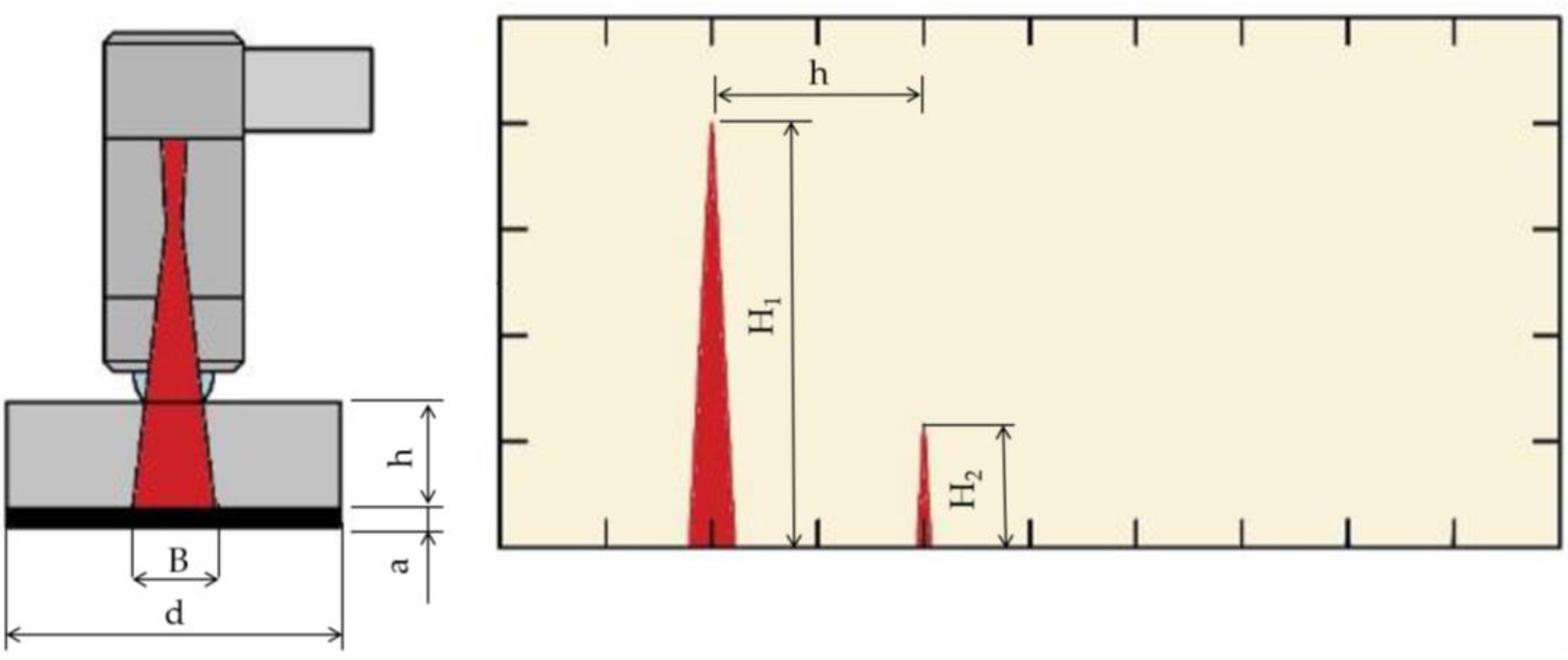
The tests were carried out using the echo technique, applying the head to the material, and generating a beam of ultrasonic waves that propagated through the material. The beam is then reflected from the bottom of the sample and returned to the ultrasonic head. The image of the wave was visualized on the screen of the ultrasonic flaw detector as a sequence of reflections with decreasing amplitude (Figure 1). GE Krautkramer’s USM 35XS ultrasonic flaw detector during the study was used. Ultrasonic testing was preceded by measurements and calibration performed on reference samples. Calibration included settings for ultrasonic wave gain, ultrasonic wave speed, pulse width, head and delay matching. The ultrasonic wave pulse amplification parameters were selected experimentally in such a way as to obtain at least two reflections from the bottom of the sample or the boundary of the adhesion joint. In addition, it is shown later in the article that the gain of the ultrasonic wave pulse has no significant effect on the obtained measurement results.
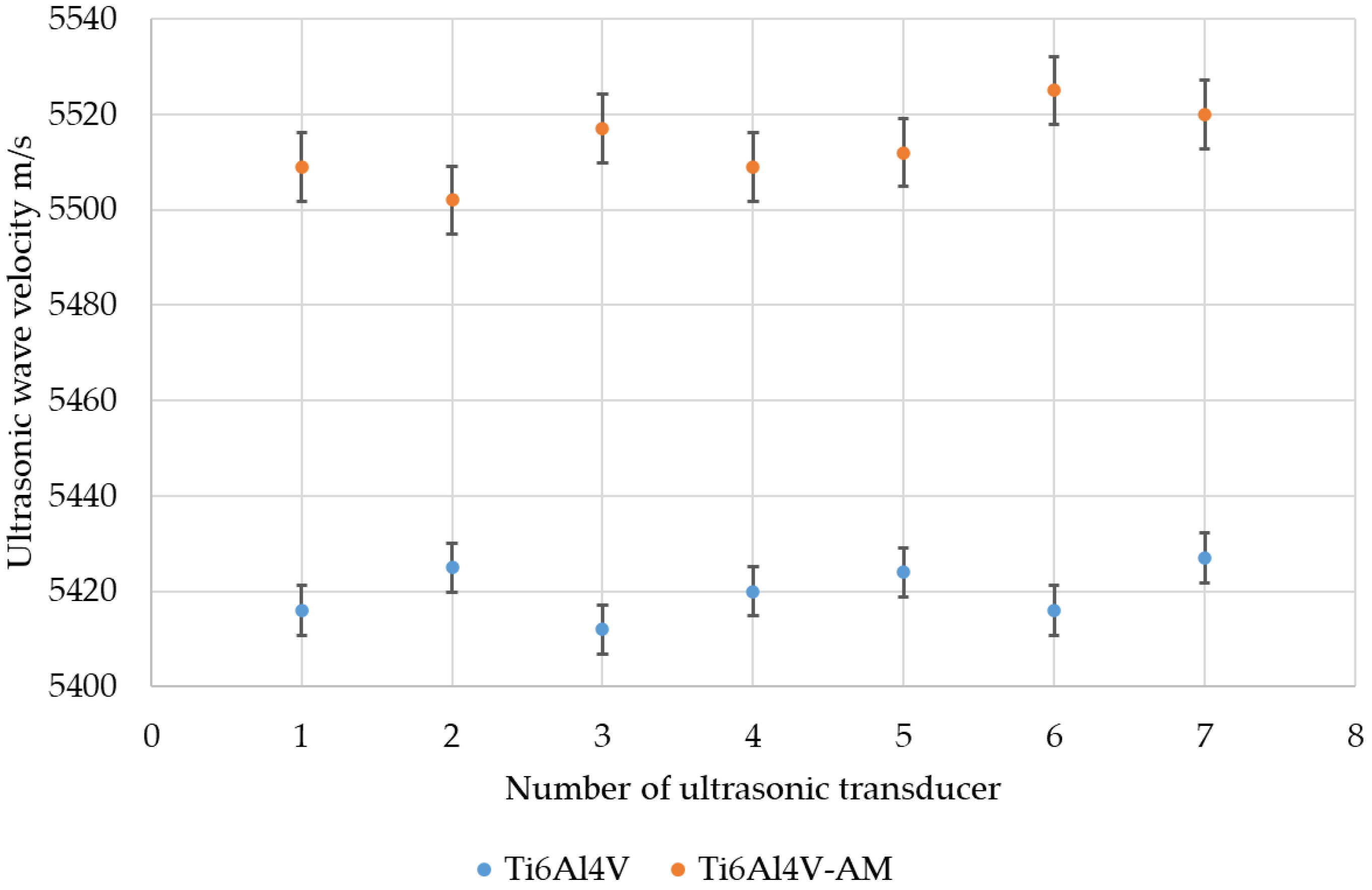
The obtained values of the mean ultrasonic wave velocity in two different materials (shown in Table 1 and Table 2) were determined from 10 measurements for each ultrasonic head. A summary of the individual wave velocity values for each head is shown in Figure 2. Higher values of ultrasonic wave velocity can be seen for the material produced by additive manufacturing technology. The difference in wave velocity is equal to around 2%. It may be caused by the different densities of the material and the more compact structure for Ti6Al4V-AM, which is formed due to the melting of individual layers during the manufacturing process.
In the next stage of the research, the effect of ultrasonic longitudinal wave pulse gain on the damping coefficient values in the tested materials was verified. For this purpose, 10 measurements of ultrasonic wave parameters were made for 25 mm thick specimens. The amplitudes of the first two pulses obtained from the bottom of the sample were recorded, and then the value of the damping coefficient was determined (Figure 3). The damping coefficient was determined based on the relationship:
α f = 20 2 · h · l o g ( H 1 H 2 )
where: H1, H2—percentage height (the amplitude value) of the first and second pulse from the bottom of the tested element, respectively, h—thickness of the element.
The gain of the ultrasonic wave pulse was also varied in the 1 dB from 20 to 35 dB range. This was the range that allowed us to obtain diagnostically useful ultrasonic longitudinal wave pulses. In this stage of ultrasonic testing, 160 measurements of wave parameters were made for the material Ti6Al4V-AM (10 measurements for each ultrasonic wave gain).
Based on the results, it was concluded that the effect of changing the pulse gain of the ultrasonic longitudinal wave on the damping coefficient is small and does not significantly affect the obtained measurement results. Moreover, this influence will also be negligible during the test of materials and joints made with additive manufacturing technology. Therefore, in the last stage of the acoustic properties study, the damping coefficients for Ti6Al4V and Ti6Al4V-AM material were determined.
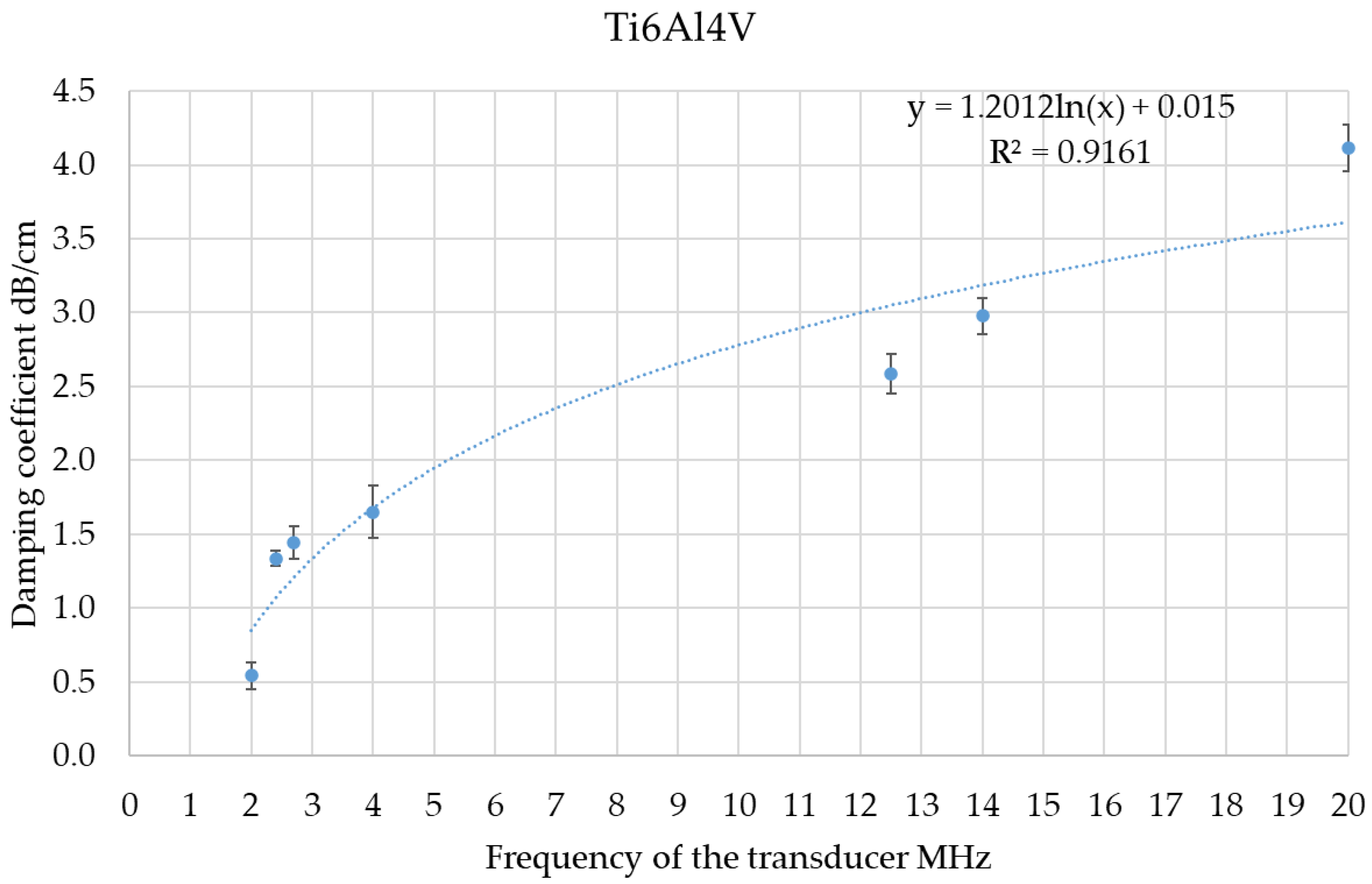
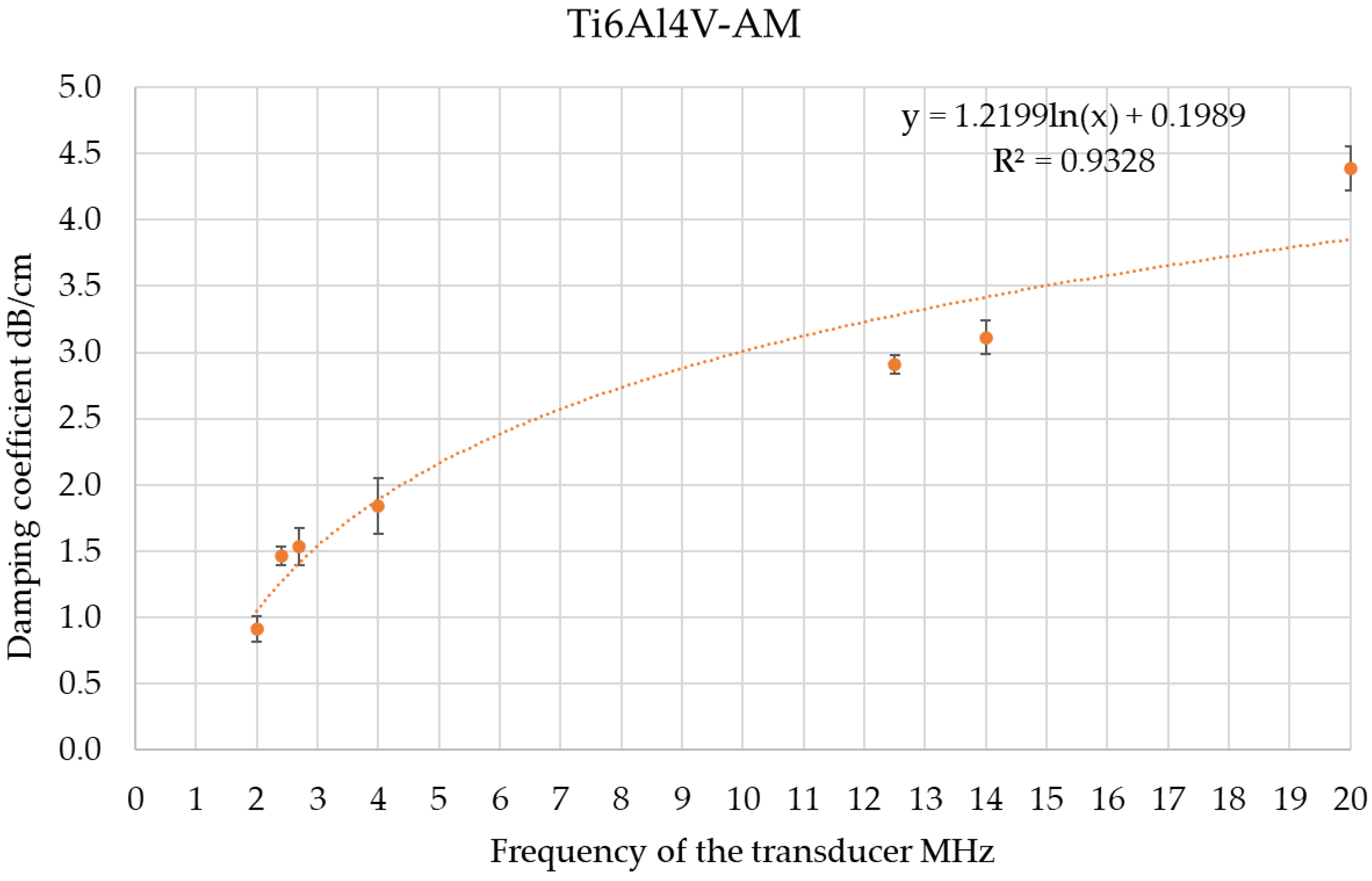
Damping tests were conducted for all three thicknesses of material made by additive manufacturing and conventional technology. As in the earlier stage of ultrasonic testing, relation 2 was used to determine the damping coefficient. For both materials and each ultrasonic head, 20 measurements of this coefficient were made. Due to the high frequency of the wave beam generated by the GE20 ultrasonic transducer, it was not possible to obtain a sequence of return echoes for the 25 and 40-mm-thick material. This high damping of the wave beam causes the lack of imaging of the second pulse of the ultrasonic wave on the screen of the ultrasonic flaw detector. The results of all damping coefficient measurements for Ti6Al4V and Ti6Al4V-AM materials, depending on the frequency of the ultrasonic transducer, are shown in Figure 4 and Figure 5.
An increase in the damping coefficient for the material made with additive manufacturing technology relative to conventional manufacturing technology was noted in each of the tested samples. The largest increase in damping coefficient for the material made with additive manufacturing technology relative to conventional technology was observed for the frequency of 2 MHz and amounted to 68%. However, for the other frequencies of ultrasonic heads, the values of the damping coefficient were at similar levels, regardless of the manufacturing process of the sample. The differences ranged from about 5% to 12%, with the material made by the conventional manufacturing process always having lower values for this parameter. The detailed differences in the damping coefficient determined for the two tested materials and ultrasonic heads at different frequencies are as follows:
  • MB2S → 67.87%,
  • KD1-6 → 9.84%,
  • KD0.8-3 → 6.12%,
  • MB4S → 11.60%,
  • KD4-12 → 12.46%,
  • KD6-16 → 4.60%,
  • GE20 → 6.67%.
The damping coefficient results are similar for the Ti6Al4V-AM and Ti6Al4V materials. Nevertheless, higher damping coefficient values were always determined for Ti6Al4V-AM. The regression curve determined from the measurement results for different frequency values of the ultrasonic transducer has a similar shape, and the coefficient of determination R2 reaches values of 0.92 and 0.93, which indicates a very good fit of the mathematical model to the damping coefficient measurement results.
The increase in damping for the highest frequencies of the ultrasonic heads used is relatively small (about five percent), which means that it should not affect the possibility of ultrasonic testing using this type of transducer. Evaluation of the type of manufacturing technology (additive manufacturing technology or conventional process) can be carried out with a low-frequency ultrasonic head (up to 2 MHz).

3. Evaluation of Adhesive Joints by Ultrasonic Method

Monitoring the condition of adhesive joints (including bonding technology) is important for their operation and durability. Destructive methods are not applicable in monitoring the condition of adhesive joints because the effect of such testing is damage to the joint. Therefore, it is important to control the condition of adhesive joints by nondestructive testing methods, including ultrasound.
The use of different manufacturing technologies in the industry requires the adaptation of inspection methods, including nondestructive methods, to the structure and properties of the materials or connections. Therefore, the authors of the article determined the possibility of using ultrasonic testing in the evaluation of the bonding connection between the Ti6Al4V as well as Ti6Al4V-AM material with 3M 490 Scotch-Weld structural adhesive. Ultrasonic testing was conducted using seven heads and two types of specimens (with three different thicknesses), as described in Section 2.
A 1 mm thick adhesive layer was applied to each sample. Before applying the adhesive, the surface of the sample was sanded with an abrasive disc and cleaned. The adhesive was applied at 20 °C and 50% humidity. Equal atmospheric conditions were maintained during the bonding of the adhesive to the sample surface. The setting time was about 24 h. Ultrasonic testing of the decibel pulse drop was then performed, as shown in Figure 6.
Twenty ultrasonic measurements of the amplitude of the first two return echoes from the adhesive joint boundary were made for each head and each sample thickness of Ti6Al4V and Ti6Al4V-AM material. The decibel drop between the first and second pulses of the ultrasonic wave from the adhesive-sample boundary was determined by:
R = 20 × log ( H 1 H 2 )
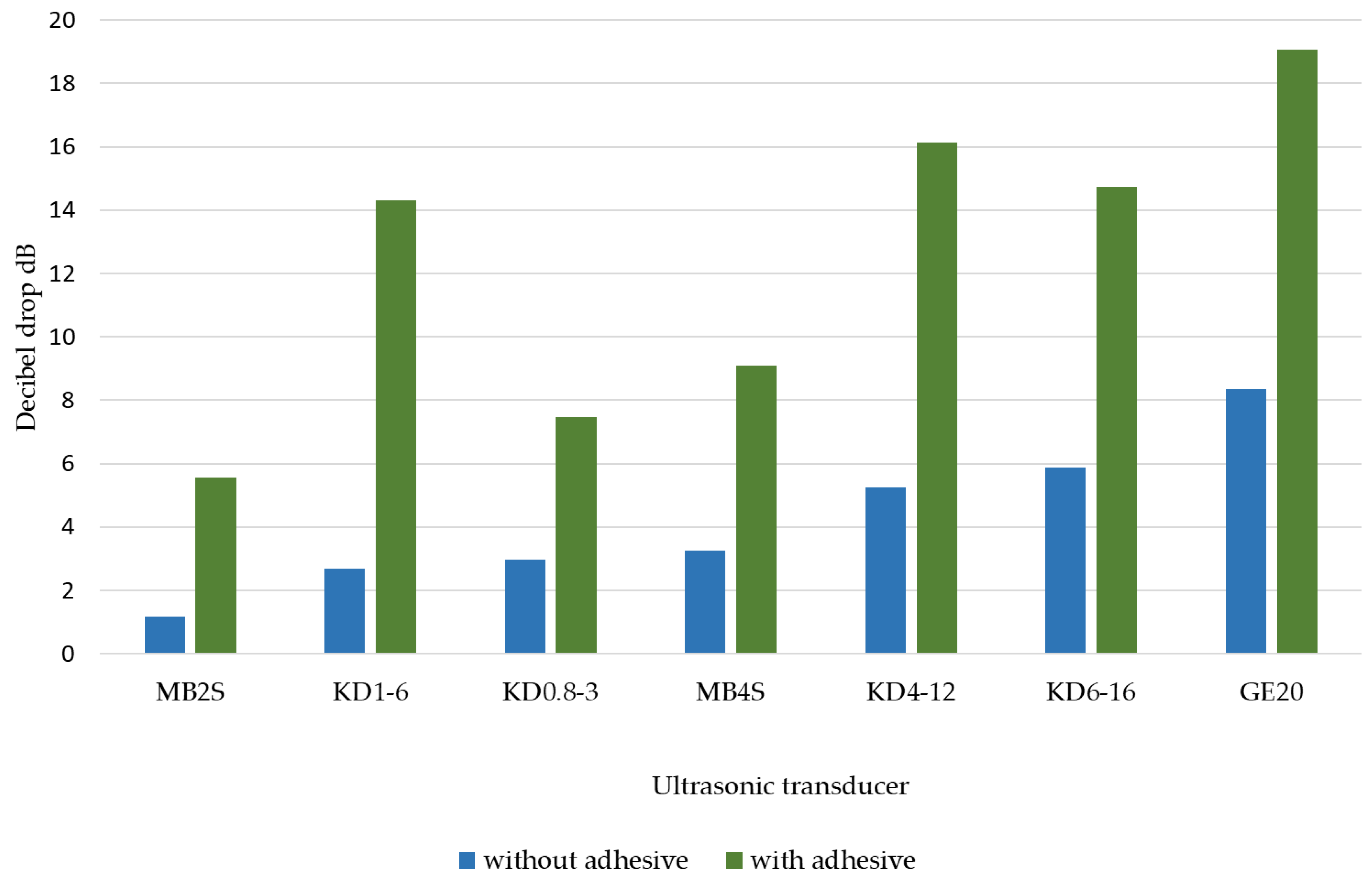
The aggregate results of the decibel drop in the amplitude of the H1 and H2 pulses for the additively and conventionally manufactured adhesive-sample joint are shown in Figure 7 and Figure 8.
Based on the test results, it should be concluded that the application of an adhesive layer causes an increase in decibel drops regardless of the material and the ultrasonic heads used during the experiment. The higher the frequency of the ultrasonic transducer, the decibel drop is also higher. The highest difference in decibel drop was obtained for the MB2S ultrasonic transducer at 2 MHz. The adhesive applied to the sample made with additive manufacturing technology caused a more than 60% increase in attenuation in such a joint in comparison with Ti6Al4V material produced by conventional methods. For the other heads, the increases in the discussed ultrasonic parameter ranged from 3 to about 20%. Nevertheless, each time, higher attenuation was obtained for the printed material than for the samples made with conventional technology. This is mainly due to the more fine-grained structure of the printed material, which results in greater energy loss of the ultrasonic wave beam propagating through the sample material [33].

4. Discussion

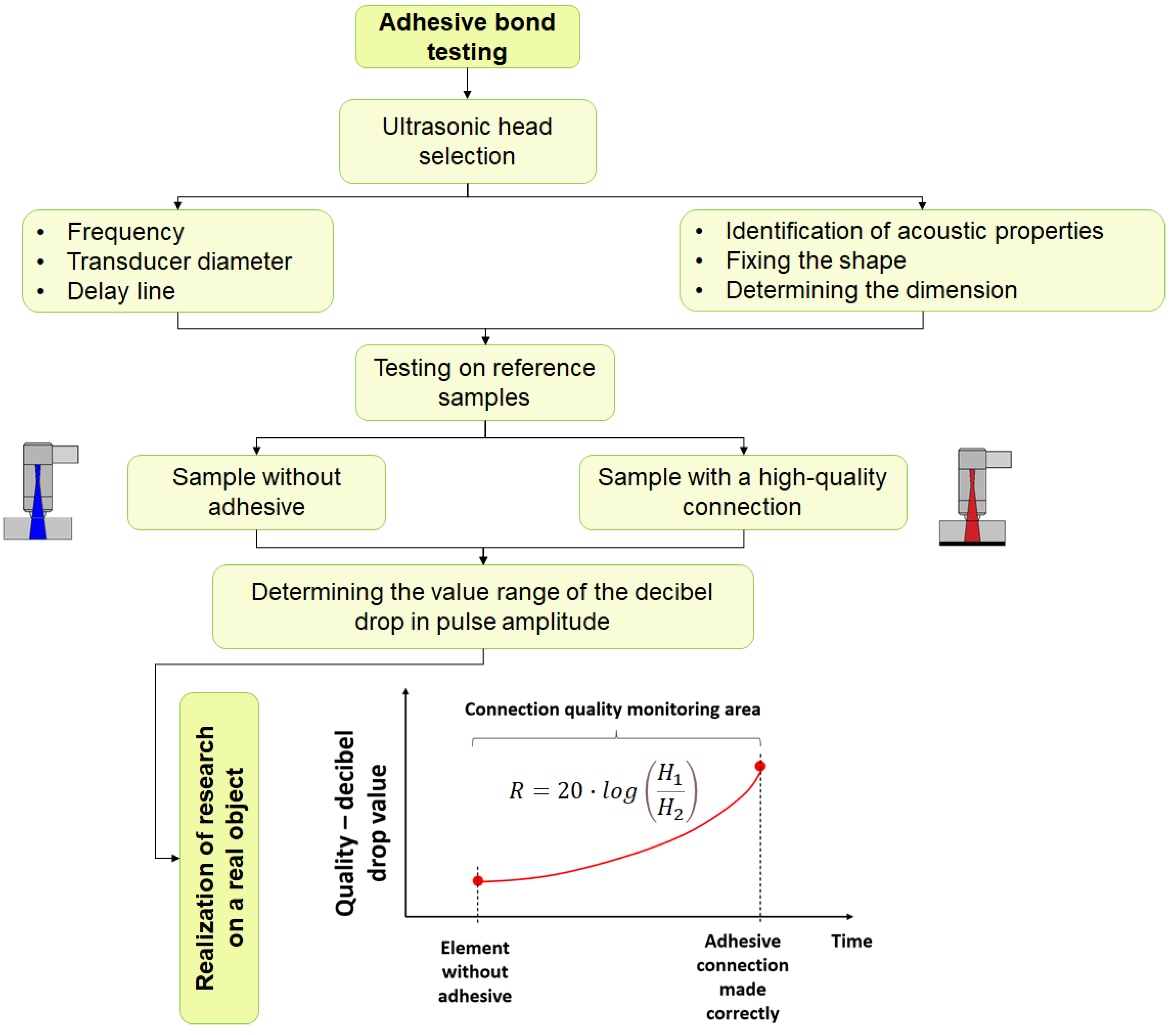
Based on the ultrasonic measurements of Ti6Al4V alloy and the determined basic acoustic properties, tests on the adhesive-sample joints were performed. Decibel drop was determined as a coefficient that can be used to evaluate and monitor the condition of the structural adhesive-alloy Ti6Al4V joint made both by modern 3D printing technology and in a standard way. This made it possible to develop guidelines applicable to the condition monitoring procedure for this type of joint, which is shown in Figure 9.
The procedure for monitoring the condition of an adhesive joint requires the selection of an ultrasonic transducer head with the appropriate frequency as well as transducer diameter depending on the type and parameters of the tested material. In addition, it is important to determine the basic acoustic parameters on a reference sample of the material made by additive manufacturing technology. Monitoring the condition of the joint involves checking the decibel drop for selected areas of the joint and comparing the obtained values with those determined on the reference sample. This type of approach gives quantitative results in terms of the adhesion of the adhesive to the material surface. This is a different proposal for locating defects or monitoring the condition of components compared to those in publications [34,35] and focuses primarily on qualitative evaluation and visualization of defects in the material structure. Lamb waves [36], as well as guided waves [37,38], are also used in adhesive bond testing. However, it is important to expand testing capabilities using longitudinal waves propagating through the adhesive joint area.
The proposed method for continuous monitoring of the condition of an adhesive joint or a component made with additive manufacturing technology is primarily applicable at the operation stage of parts and machines. In the literature [39,40,41], there are known methods for monitoring the condition of parts made by 3D metal printing technology that allow non-contact evaluation of individual layers and existing defects in the manufactured part. Nevertheless, this is possible only in the laboratory and under constant conditions [42]. Determination of decibel drop measure is possible under various conditions and can be carried out periodically or continuously with a remote data transmission method for assessing the condition of the adhesive bond and other parts manufactured with additive manufacturing technology. Similar conclusions from the use of decibel drop measure were obtained by the authors of the paper [43].

5. Conclusions

The article presents the results of tests on Ti6Al4V material produced using additive manufacturing technology as well as the conventional production method (rod drawing). In the first stage of the research, the basic acoustic properties were determined for selected ultrasonic heads with frequencies in the range of 2–20 MHz. The effective diameter of the transducer for the tested samples was determined, as well as the speed of the ultrasonic wave and its damping. The conclusion of this stage of the research is the determined dependence of the ultrasonic wave damping coefficient on the ultrasonic head transducer frequency for both Ti6Al4V and Ti6Al4V-AM samples.
The second stage of the study used the decibel drop between the amplitudes of the first two return pulses to evaluate the adhesive joint of Ti6Al4V and Ti6Al4V-AM material to a structural adhesive widely used in industry. The results of the study confirmed that a higher decibel drop was observed for the samples made with additive manufacturing technology, which may be due to the structure of the Ti6Al4V-AM material.
In the next stages of the study, the authors plan to perform an evaluation of acoustic properties for other materials made with additive manufacturing technology (e.g., IN 718, AlSi10Mg) in order to expand the knowledge of properties of materials made by conventional technology and using the laser bed fusion method. In addition, further studies of adhesive joints of materials made with different technologies are planned to develop nondestructive measures and methods to control the quality and monitor the condition of the adhesive joint during the operation of the machines.

Author Contributions

Conceptualization, J.K., M.J. and D.U.; methodology, J.K., M.J. and M.N.; software, K.S. and K.G.; validation, J.K., D.U. and T.K.; formal analysis, M.J. and K.G.; investigation, J.K.; resources, K.S., T.K., K.G. and M.N.; data curation, J.K.; writing—original draft preparation, J.K. and D.U.; writing—review and editing, J.K., D.U. and M.J.; visualization, J.K. and K.S.; supervision, M.J., T.K. and M.N.; project administration, K.S.; funding acquisition, M.N., K.G. and T.K. All authors have read and agreed to the published version of the manuscript.

Funding

This work was supported by the Polish National Centre for Research and Development under the grant—decision no. DWP/TECHMATSTRATEG-III/136/2020.

Institutional Review Board Statement

Not applicable.

Informed Consent Statement

Not applicable.

Data Availability Statement

The data presented in this study are available on request from the corresponding author.

Conflicts of Interest

The authors declare no conflict of interest.

References

  1. Sanchez, A.; Smith, P.; Xu, Z.; Gaspard, G.; Hyde, C.J.; Wits, W.W.; Ashcroft, I.A.; Chen, H.; Clare, A.T. Powder Bed Fusion of nickel-based superalloys: A review. Int. J. Mach. Tools Manuf. 2021, 165, 103729. [Google Scholar] [CrossRef]
  2. Hosseini, E.; Popovich, V. A review of mechanical properties of additively manufactured Inconel 718. Addit. Manuf. 2019, 30, 100877. [Google Scholar] [CrossRef]
  3. Warguła, Ł.; Kaczmarzyk, P. Legal Regulations of Restrictions of Air Pollution Made by Mobile Positive Pressure Fans—The Case Study for Europe: A Review. Energies 2022, 15, 7672. [Google Scholar] [CrossRef]
  4. Warguła, Ł.; Kukla, M.; Wieczorek, B.; Krawiec, P. Energy consumption of the wood size reduction processes with employ-ment of a low-power machines with various cutting mechanisms. Renew. Energy 2022, 181, 630–639. [Google Scholar] [CrossRef]
  5. Bartkowski, D.; Bartkowska, A.; Jurči, P.; Przestacki, D. Influence of Manufacturging Parameters on Microstructure, Chemical Composition, Microhardness, Corrosion and Wear Resistance of ZrC Coatings Produced on Monel®400 Using Laser Processing Technology. Coatings 2022, 12, 651. [Google Scholar] [CrossRef]
  6. Sharma, S.K.; Grewal, H.S.; Saxena, K.K.; Mohammed, K.A.; Prakash, C.; Davim, J.P.; Buddhi, D.; Raju, R.; Mohan, D.G.; Tomków, J. Advancements in the Additive Manufacturing of Magnesium and Aluminum Alloys through Laser-Based Approach. Materials 2022, 15, 8122. [Google Scholar] [CrossRef]
  7. Bhavar, V.; Kattire, P.; Patil, V.; Khot, S.; Gujar, K.; Singh, R. A review on powder bed fusion technology of metal additive manufacturing. In Additive Manufacturing Handbook; CRC Press: Boca Raton, FL, USA, 2017; pp. 251–261. [Google Scholar]
  8. Frazier, W.E. Metal Additive Manufacturing: A Review. J. Mater. Eng. Perform. 2014, 23, 1917–1928. [Google Scholar] [CrossRef]
  9. du Preez, W.B. Towards Qualification of Additively Manufactured Ti6Al4V (ELI) Medical Implants. JOM 2018, 71, 655–661. [Google Scholar] [CrossRef]
  10. Ramosena, L.A.; Dzogbewu, T.C.; du Preez, W. Direct Metal Laser Sintering of the Ti6Al4V Alloy from a Powder Blend. Materials 2022, 15, 8193. [Google Scholar] [CrossRef]
  11. Liu, Z.; Lyu, T.; Zou, Y. A Review on Additive Manufacturing of Titanium Alloys for Aerospace Applications: Directed Energy Deposition and Beyond Ti-6Al-4V. Process.-Microstruct.-Prop. Relatsh. Addit. Manuf. Ti Alloys 2021, 73, 1804–1818. [Google Scholar] [CrossRef]
  12. Olmo, J.A.; Alosno, J.M.; Ronco-Campana, A.; Saez-Martinez, V.; Perez-Gonzalez, R.; Rothie, A.J.; Tighe, B.J.; Vilas-Vilela, J.L.; Perez-Avarez, L. Effectiveness of physicochemical techniques on the activation of Ti6Al4V surface with improved bio-compatibility and antibacterial properties. Surf. Coat. Technol. 2022, 447, 128821. [Google Scholar] [CrossRef]
  13. Bocchetta, P.; Chen, L.-Y.; Tardelli, J.; Reis, A.; Almeraya-Calderón, F.; Leo, P. Passive Layers and Corrosion Resistance of Biomedical Ti-6Al-4V and β-Ti Alloys. Coatings 2021, 11, 487. [Google Scholar] [CrossRef]
  14. Chen, L.-Y.; Cui, Y.-W.; Zhang, L.-C. Recent Development in Beta Titanium Alloys for Biomedical Applications. Metals 2020, 10, 1139. [Google Scholar] [CrossRef]
  15. Shukla, K.A.; Balasubramaniam, R. Effect of surface treatment on electrochemical behavior of CP Ti, Ti–6Al–4V and Ti–13Nb–13Zr alloys in simulated human body fluid. Corros. Sci. 2006, 48, 1696–1720. [Google Scholar] [CrossRef]
  16. Zhou, Y.L.; Niinomi, M.; Akahori, T.; Fukui, H.; Toda, H. Corrosion resistance and biocompatibility of Ti–Ta alloys for bio-medical applications. Mater. Sci. Eng. A 2005, 398, 28–36. [Google Scholar] [CrossRef]
  17. Attanasio, A.; Gelfi, M.; Pola, A.; Ceretti, E.; Giardini, C. Influence of Material Microstructures in Micromilling of Ti6Al4V Alloy. Materials 2013, 6, 4268–4283. [Google Scholar] [CrossRef] [Green Version]
  18. Lekkala, R.; Bajpai, V.; Singh, R.K.; Joshi, S.S. Characterization and modeling of burr formation in micro-end milling. Precis. Eng. 2011, 35, 625–637. [Google Scholar] [CrossRef]
  19. Wu, H.; Zhang, S. Effects of cutting conditions on the milling process of titanium alloy Ti6Al4V. Int. J. Adv. Manuf. Technol. 2014, 77, 2235–2240. [Google Scholar] [CrossRef]
  20. Li, K.-M.; Chou, S.-Y. Experimental evaluation of minimum quantity lubrication in near micro-milling. J. Mater. Process. Technol. 2010, 210, 2163–2170. [Google Scholar] [CrossRef]
  21. da Costa, P.R.; Sardinha, M.; Reis, L.; Freitas, M.; Fonte, M. Ultrasonic fatigue testing in as-built and polished Ti6Al4V alloy manufactured by SLM. Forces Mech. 2021, 4, 100024. [Google Scholar] [CrossRef]
  22. Spierings, A.; Starr, T.; Wegener, K. Fatigue performance of additive manufactured metallic parts. Rapid Prototyp. J. 2013, 19, 88–94. [Google Scholar] [CrossRef]
  23. Li, P.; Warner, D.; Fatemi, A.; Phan, N. Critical assessment of the fatigue performance of additively manufactured Ti–6Al–4V and perspective for future research. Int. J. Fatigue 2016, 85, 130–143. [Google Scholar] [CrossRef]
  24. Mian, J.; Razmi, J.; Ladani, L. Defect analysis and fatigue strength prediction of as-built Ti6Al4V parts, produced using electron beam melting (EBM) AM technology. Materialia 2021, 16, 101041. [Google Scholar] [CrossRef]
  25. Liu, F.; Chen, Y.; Li, L.; Wang, C.; Wang, Q.; Liu, Y. Interior defect-induced crack initiation mechanism and initial growth behavior for Ti6Al4V alloy fabricated using laser powder bed fusion. J. Mater. Res. Technol. 2022, 21, 2089–2104. [Google Scholar] [CrossRef]
  26. Szymanik, B.; Psuj, G.; Hashemi, M.; Lopato, P. Detection and Identification of Defects in 3D-Printed Dielectric Structures via Thermographic Inspection and Deep Neural Networks. Materials 2021, 14, 4168. [Google Scholar] [CrossRef]
  27. Kim, C.; Yin, H.; Shmatok, A.; Prorok, B.C.; Lou, X.; Matlack, K.H. Ultrasonic nondestructive evaluation of laser powder bed fusion 316L stainless steel. Addit. Manuf. 2021, 38, 101800. [Google Scholar] [CrossRef]
  28. Allam, A.; Alfahmi, O.; Patel, H.; Sugino, C.; Harding, M.; Ruzzene, M.; Erturk, A. Ultrasonic testing of thick and thin In-conel 625 alloys manufactured by laser powder bed fusion. Ultrasonics 2022, 125, 106780. [Google Scholar] [CrossRef]
  29. Lopez, A.; Bacelar, R.; Pires, I.; Santos, T.G.; Sousa, J.P.; Quintino, L. Non-destructive testing application of radiography and ultrasound for wire and arc additive manufacturing. Addit. Manuf. 2018, 21, 298–306. [Google Scholar] [CrossRef]
  30. Davis, G.; Nagarajah, R.; Palanisamy, S.; Rashid, R.A.R.; Rajagopal, P.; Balasubramaniam, K. Laser ultrasonic inspection of additive manufactured components. Int. J. Adv. Manuf. Technol. 2019, 102, 2571–2579. [Google Scholar] [CrossRef]
  31. Yu, J.; Zhang, D.; Li, H.; Song, C.; Zhou, X.; Shen, S.; Zhang, G.; Yang, Y.; Wang, H. Detection of Internal Holes in Additive Manufactured Ti-6Al-4V Part Using Laser Ultrasonic Testing. Appl. Sci. 2020, 10, 365. [Google Scholar] [CrossRef]
  32. Chen, S.-L. Review of Laser-Generated Ultrasound Transmitters and Their Applications to All-Optical Ultrasound Transducers and Imaging. Appl. Sci. 2016, 7, 25. [Google Scholar] [CrossRef]
  33. Nguyen, H.D.; Pramanik, A.; Basak, A.; Dong, Y.; Prakash, C.; Debnath, S.; Shankar, S.; Jawahir, I.; Dixit, S.; Buddhi, D. A critical review on additive manufacturing of Ti-6Al-4V alloy: Microstructure and mechanical properties. J. Mater. Res. Technol. 2022, 18, 4641–4661. [Google Scholar] [CrossRef]
  34. Liu, Y.; Yang, S.; Liu, X. Detection and Quantification of Damage in Metallic Structures by Laser-Generated Ultrasonics. Appl. Sci. 2018, 8, 824. [Google Scholar] [CrossRef] [Green Version]
  35. Lu, Q.Y.; Wong, C.H. Additive manufacturing process monitoring and control by non-destructive testing techniques: Challenges and in-process monitoring. Virtual Phys. Prototyp. 2018, 13, 39–48. [Google Scholar] [CrossRef]
  36. Marks, R.; Clarke, A.; Featherston, C.; Paget, C.; Pullin, R. Lamb Wave Interaction with Adhesively Bonded Stiffeners and Disbonds Using 3D Vibrometry. Appl. Sci. 2016, 6, 12. [Google Scholar] [CrossRef] [Green Version]
  37. Leiderman, R.; Braga, A.M. Scattering of guided waves by defective adhesive bonds in multilayer anisotropic plates. Wave Motion 2017, 74, 93–104. [Google Scholar] [CrossRef]
  38. Leiderman, R.; Figueroa, J.C.; Braga, A.M.B.; Rochinha, F.A. Scattering of ultrasonic guided waves by heterogeneous inter-faces in elastic multi-layered structures. Wave Motion 2016, 63, 68–82. [Google Scholar] [CrossRef]
  39. Everton, S.K.; Hirsch, M.; Stravroulakis, P.; Leach, R.K.; Clare, A.T. Review of in-situ process monitoring and in-situ metrol-ogy for metal additive manufacturing. Mater. Des. 2016, 95, 431–445. [Google Scholar] [CrossRef]
  40. Gomez, C.; Guardia, A.; Mantari, J.L.; Coronado, A.M.; Reddy, J.N. A contemporary approach to the MSE paradigm powered by Artificial Intelligence from a review focused on Polymer Matrix Composites. Mech. Adv. Mater. Struct. 2021, 29, 3076–3096. [Google Scholar] [CrossRef]
  41. Honarvar, F.; Varvani-Farahani, A. A review of ultrasonic testing applications in additive manufacturing: Defect evaluation, material characterization, and process control. Ultrasonics 2020, 108, 106227. [Google Scholar] [CrossRef]
  42. Yang, C.H.; Jeyaprakash, N.; Chan, C.K. Inhomogeneous mechanical properties in additively manufactured parts characterized by nondestructive laser ultrasound technique. NDTE Int. 2020, 116, 102340. [Google Scholar] [CrossRef]
  43. Yilmaz, B.; Asokkumar, A.; Jasiūnienė, E.; Kažys, R.J. Air-Coupled, Contact, and Immersion Ultrasonic Non-Destructive Testing: Comparison for Bonding Quality Evaluation. Appl. Sci. 2020, 10, 6757. [Google Scholar] [CrossRef]
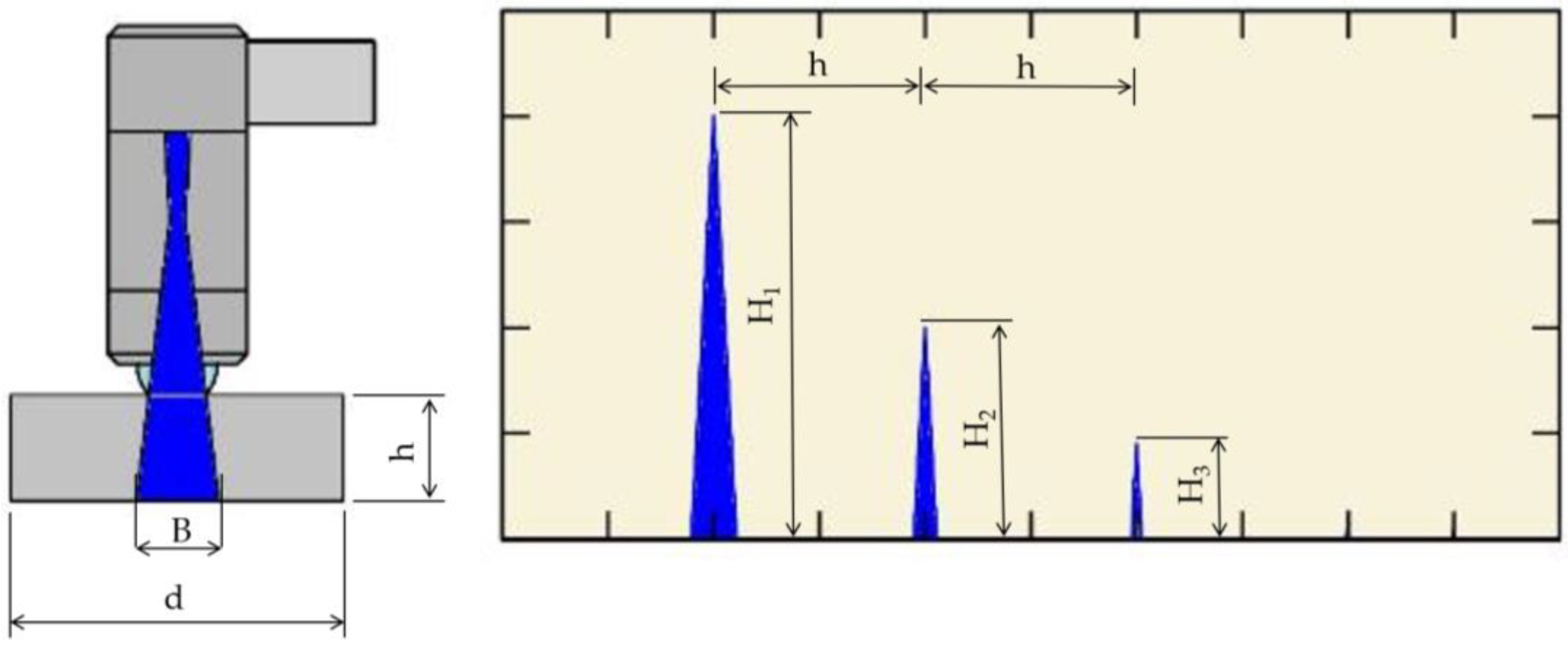
Figure 1. Ultrasonic testing—scheme; h = 10, 25 and 40 mm, d = 25 mm, B—beam diameter in mm, H1, H2, H3—amplitude of pulses from the bottom of the specimen.
Applsci 13 00371 g001
Figure 2. Average ultrasonic wave velocity values for the material Ti6Al4V and Ti6Al4V-AM.
Applsci 13 00371 g002
Figure 3. Dependence of the gain of the wave pulse on the attenuation of an ultrasonic wave in a material.
Applsci 13 00371 g003
Figure 4. Dependence of the ultrasonic transducer frequency on damping coefficient for Ti6Al4V material.
Applsci 13 00371 g004
Figure 5. Dependence of the ultrasonic transducer frequency on damping coefficient for Ti6Al4V-AM material.
Applsci 13 00371 g005
Figure 6. Ultrasonic testing of adhesive joint—scheme; h = 10, 25 and 40 mm, d = 25 mm, a = 1 mm.
Applsci 13 00371 g006
Figure 7. Decibel drop for samples with and without adhesive of Ti6Al4V material.
Applsci 13 00371 g007
Figure 8. Decibel drop for samples with and without adhesive of Ti6Al4V-AM material.
Applsci 13 00371 g008
Figure 9. A procedure during monitoring the condition of the adhesive bond by ultrasonic method.
Applsci 13 00371 g009
Table 3. The diameter of the ultrasonic wave beam B at the bottom of the tested samples.
Ti6Al4V—Beam
Diameter mm
Ti6Al4V-AM—Beam
Diameter mm
Sample Height—h102540102540
MB2S5.012.520.05.112.820.4
KD1-63.48.613.73.58.713.9
KD0.8-33.07.411.93.07.612.1
MB4S2.46.19.82.56.210.0
KD4-121.33.25.21.33.35.3
KD6-162.35.89.32.45.99.5
GE201.64.16.51.74.16.6
Disclaimer/Publisher’s Note: The statements, opinions and data contained in all publications are solely those of the individual author(s) and contributor(s) and not of MDPI and/or the editor(s). MDPI and/or the editor(s) disclaim responsibility for any injury to people or property resulting from any ideas, methods, instructions or products referred to in the content.