
A Novel Strategy for Automatic Mode Pairing on the Model Updating of Railway Systems with Nonproportional Damping


Abstract
:1. Introduction
- -
- The development of a mode-pairing formulation dedicated to complex modes based on an energy-based criterion and relying on a state-space formulation. The existing criteria for complex mode shapes reveal weaknesses and tend to fail in several situations;
- -
- The evaluation of the performance of the developed mode-pairing criterion based on a case study involving a highly complex FE model of a railway vehicle and experimental modal parameters. In the existing mode pairing criteria, the validation is usually performed based on simple numerical or analytical examples. Additionally, the experimental restrictions associated with the positioning and number of sensors, noise and environmental interference create more challenging conditions to evaluate the performance of the pairing criteria.
2. Review of Existing Mode-Pairing Criteria
2.1. Modal Assurance Criterion (MAC)
2.2. Extended Modal Assurance Criterion (MACX)
2.3. Frequency Domain Assurance Criterion (FDAC)
3. Mode Pairing Using the Energy-Based Modal Assurance Criterion (EMAC)
3.1. Real Modes
3.2. Complex Modes
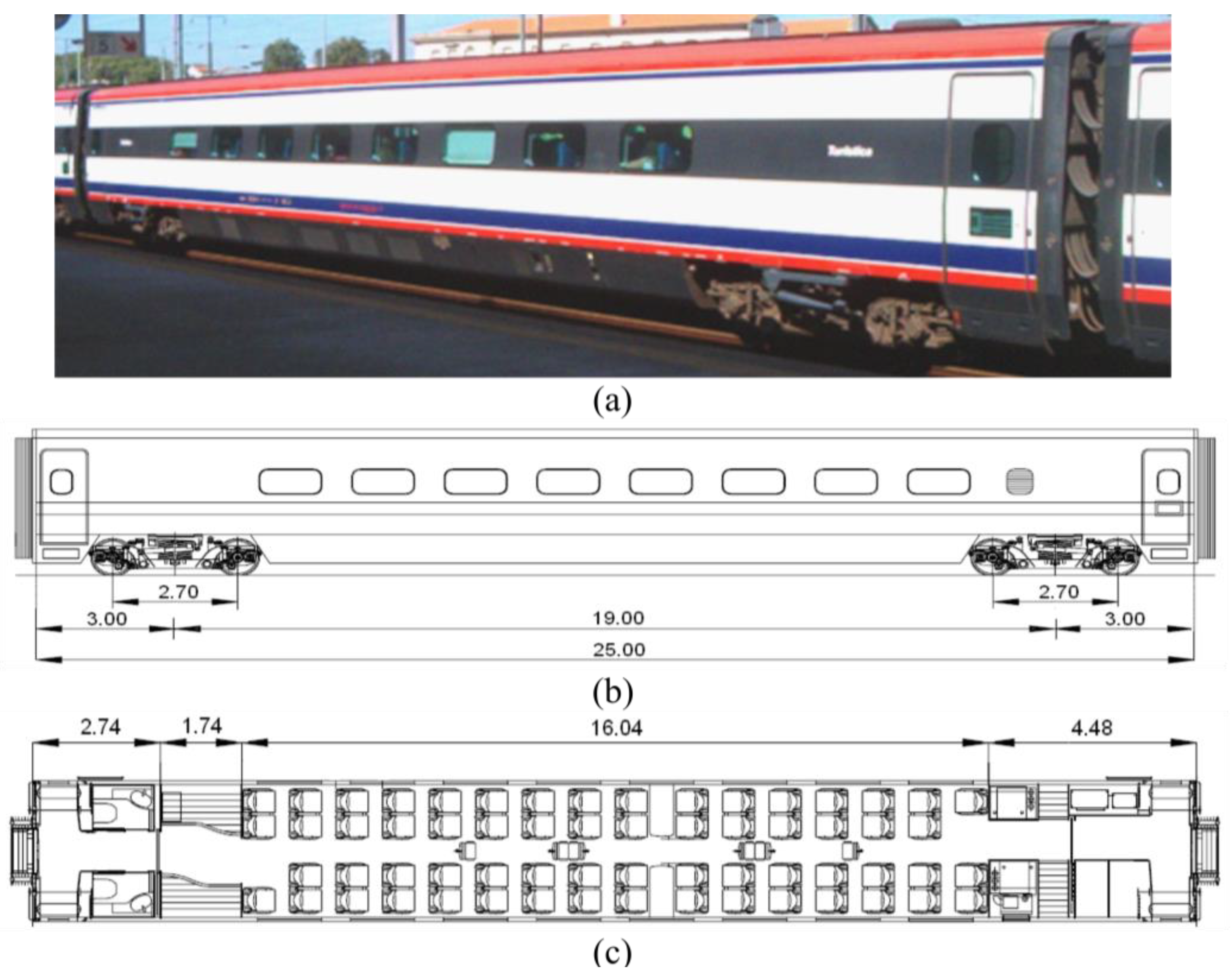
4. Case Study
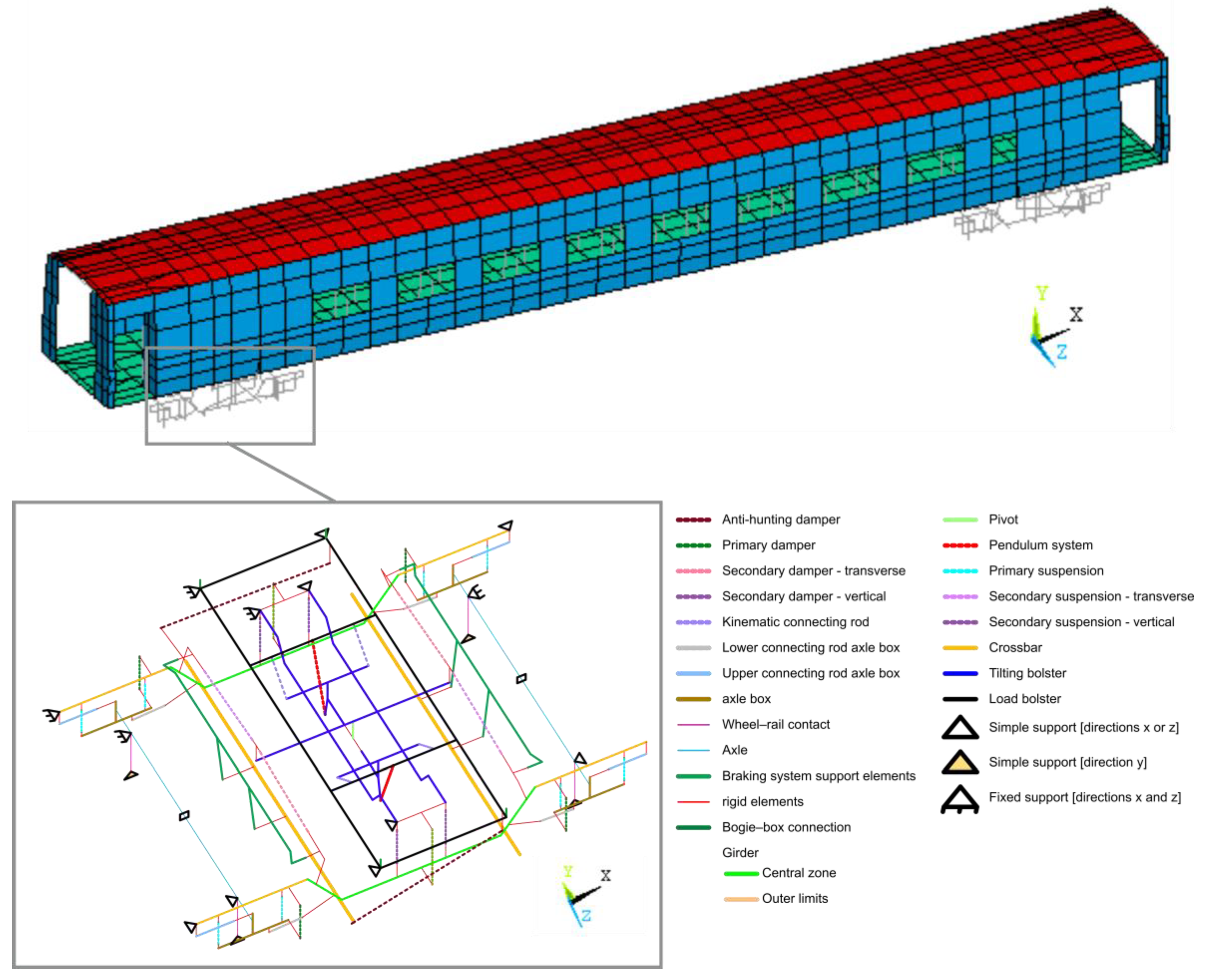
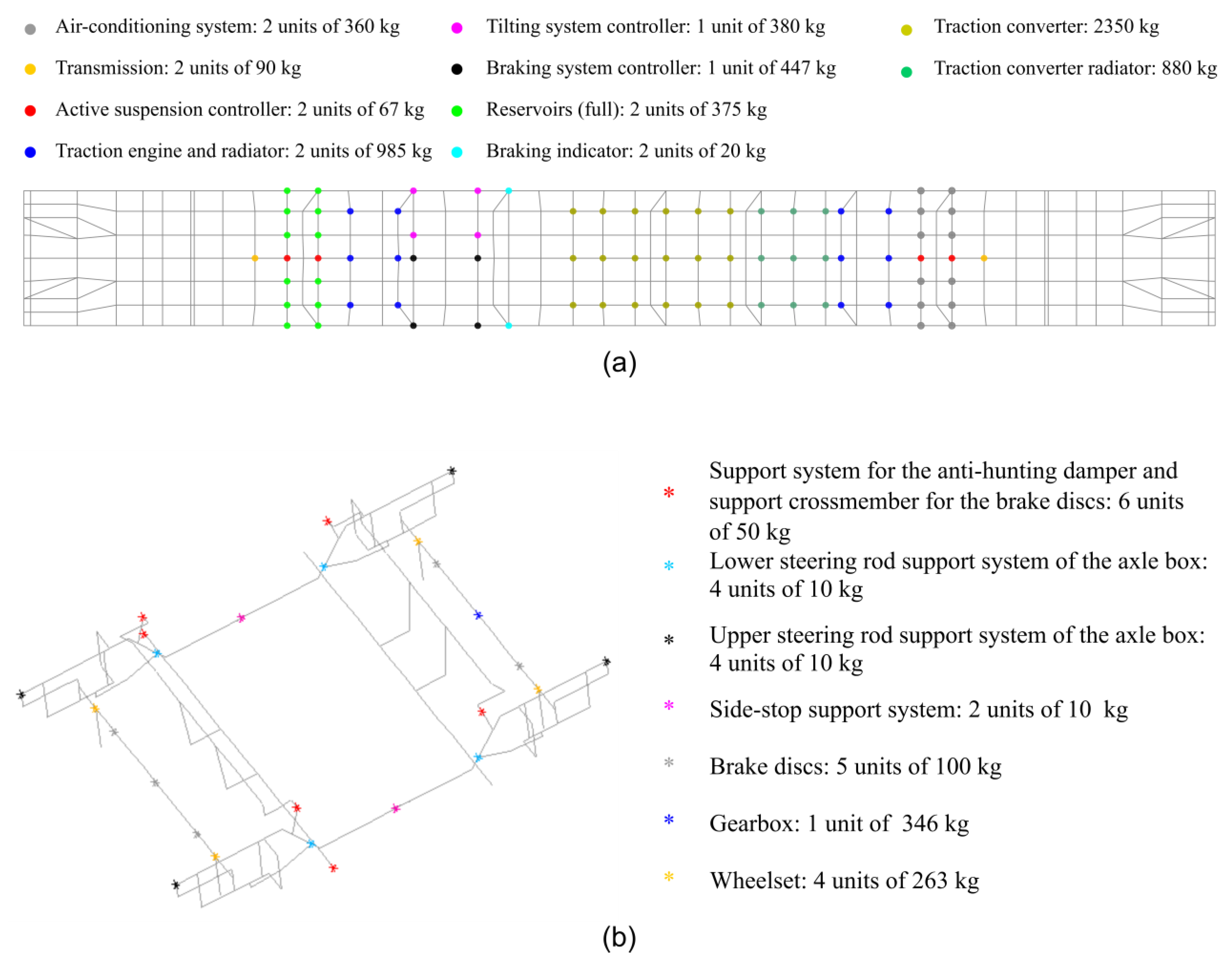
4.1. Numerical Model
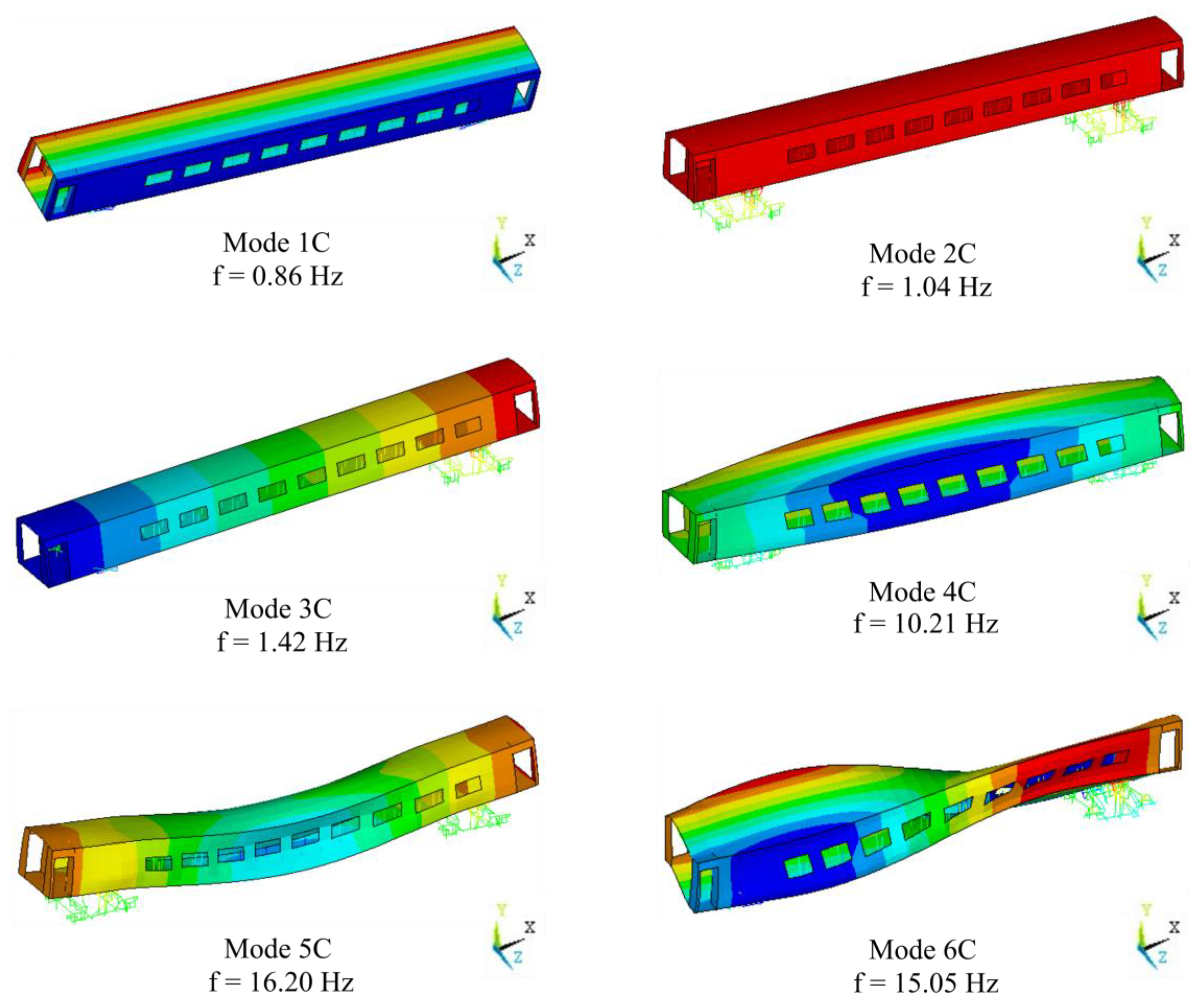
4.2. Mode Pairing
5. Conclusions
Author Contributions
Funding
Institutional Review Board Statement
Informed Consent Statement
Data Availability Statement
Conflicts of Interest
References
- Bragança, C.; Neto, J.; Pinto, N.; Montenegro, P.A.; Ribeiro, D.; Carvalho, H.; Calçada, R. Calibration and Validation of a Freight Wagon Dynamic Model in Operating Conditions Based on Limited Experimental Data. Veh. Syst. Dyn. 2022, 60, 3024–3050. [Google Scholar] [CrossRef]
- Silva, R.; Ribeiro, D.; Bragança, C.; Costa, C.; Arêde, A.; Calçada, R. Model Updating of a Freight Wagon Based on Dynamic Tests under Different Loading Scenarios. Appl. Sci. 2021, 11, 10691. [Google Scholar] [CrossRef]
- Ribeiro, D.; Calçada, R.; Delgado, R.; Brehm, M.; Zabel, V. Finite Element Model Updating of a Bowstring-Arch Railway Bridge Based on Experimental Modal Parameters. Eng. Struct. 2012, 40, 413–435. [Google Scholar] [CrossRef]
- Ribeiro, D.; Calçada, R.; Delgado, R.; Brehm, M.; Zabel, V. Finite-Element Model Calibration of a Railway Vehicle Based on Experimental Modal Parameters. Veh. Syst. Dyn. 2013, 51, 821–856. [Google Scholar] [CrossRef]
- Meixedo, A.; Ribeiro, D.; Calçada, R.; Delgado, R. Global and Local Dynamic Effects on a Railway Viaduct with Precast Deck. In Proceedings of the 2nd International Conference on Railway Technology: Research, Development and Maintenance, Ajaccio, France, 8–11 April 2014. [Google Scholar] [CrossRef]
- Ribeiro, D.; Bragança, C.; Costa, C.; Jorge, P.; Silva, R.; Arêde, A.; Calçada, R. Calibration of the Numerical Model of a Freight Railway Vehicle Based on Experimental Modal Parameters. Structures 2022, 38, 108–122. [Google Scholar] [CrossRef]
- Clementi, F.; Pierdicca, A.; Formisano, A.; Catinari, F.; Lenci, S. Numerical Model Upgrading of a Historical Masonry Building Damaged during the 2016 Italian Earthquakes: The Case Study of the Podestà Palace in Montelupone (Italy). J. Civ. Struct. Health Monit. 2017, 7, 703–717. [Google Scholar] [CrossRef]
- Costa, C.; Ribeiro, D.; Jorge, P.; Silva, R.; Arêde, A.; Calçada, R. Calibration of the Numerical Model of a Stone Masonry Railway Bridge Based on Experimentally Identified Modal Parameters. Eng. Struct. 2016, 123, 354–371. [Google Scholar] [CrossRef]
- Pierdicca, A.; Clementi, F.; Fortunati, A.; Lenci, S. Tracking Modal Parameters Evolution of a School Building during Retrofitting Works. Bull. Earthq. Eng. 2019, 17, 1029–1052. [Google Scholar] [CrossRef]
- Alves, V.N.; de Oliveira, M.M.; Ribeiro, D.; Calçada, R.; Cury, A. Model-Based Damage Identification of Railway Bridges Using Genetic Algorithms. Eng. Fail. Anal. 2020, 118, 104845. [Google Scholar] [CrossRef]
- Huang, M.-S.; Gül, M.; Zhu, H.-P. Vibration-Based Structural Damage Identification under Varying Temperature Effects. J. Aerosp. Eng. 2018, 31, 04018014. [Google Scholar] [CrossRef]
- Brehm, M.; Zabel, V.; Bucher, C. An Automatic Mode Pairing Strategy Using an Enhanced Modal Assurance Criterion Based on Modal Strain Energies. J. Sound Vib. 2010, 329, 5375–5392. [Google Scholar] [CrossRef]
- Ewins, D.J. Model Validation: Correlation for Updating. Sadhana Acad. Proc. Eng. Sci. 2000, 25, 221–234. [Google Scholar] [CrossRef]
- Lein, C.; Beitelschmidt, M. Comparative Study of Model Correlation Methods with Application to Model Order Reduction. In Proceedings of the ISMA 2014—International Conference on Noise and Vibration Engineering and USD 2014–International Conference on Uncertainty in Structural Dynamics, Leuven, Belgium, 15–17 September 2014; pp. 2683–2700. [Google Scholar]
- Pascual, R.; Golinval, J.C.; Razeto, M. A Frequency Domain Correlation Techinique for Model Correlation and Updating. In Proceedings of the 15th International Modal Analysis Conference (IMAC XV), Orlando, FL, USA, 3–7 February 1997. [Google Scholar]
- Allemang, R.J.; Brown, D.L. Correlation Coefficient for Modal Vector Analysis. In Proceedings of the International Modal Analysis Conference & Exhibit, Orlando, FL, USA, 6–9 February 1982; pp. 110–116. [Google Scholar]
- Ewins, D.J. Modal Testing: Theory, Practice and Application, 2nd ed.; Wiley: Baldock, UK, 2009; ISBN 978-0863802188. [Google Scholar]
- Pastor, M.; Binda, M.; Harčarik, T. Modal Assurance Criterion. Procedia Eng. 2012, 48, 543–548. [Google Scholar] [CrossRef]
- Heylen, W.; Janter, T. Extensions of the Modal Assurance Criterion. J. Vib. Acoust. Trans. ASME 1990, 112, 468–472. [Google Scholar] [CrossRef]
- Vacher, P.; Jacquier, B.; Bucharles, A. Extensions of the MAC Criterion to Complex Modes. In Proceedings of the ISMA 2010–International Conference on Noise and Vibration Engineering, including USD 2010, Leuven, Belgium, 20–22 September 2010; pp. 2713–2725. [Google Scholar]
- Allemang, R.J. The Modal Assurance Criterion–Twenty Years of Use and Abuse. Sound Vib. 2003, 37, 14–21. [Google Scholar]
- Sternharz, G.; Kalganova, T.; Mares, C.; Meyeringh, M. Comparative Performance Assessment of Methods for Operational Modal Analysis during Transient Order Excitation. Mech. Syst. Signal Process. 2022, 169, 108719. [Google Scholar] [CrossRef]
- Ticona Melo, L.R.; Ribeiro, D.; Calçada, R.; Bittencourt, T.N. Validation of a Vertical Train–Track–Bridge Dynamic Interaction Model Based on Limited Experimental Data. Struct. Infrastruct. Eng. 2020, 16, 181–201. [Google Scholar] [CrossRef]
- Ribeiro, D.; Calçada, R.; Brehm, M.; Zabel, V. Calibration of the Numerical Model of a Track Section over a Railway Bridge Based on Dynamic Tests. Structures 2021, 34, 4124–4141. [Google Scholar] [CrossRef]
- Brehm, M. Vibration-Based Model Updating: Reduction and Quantification of Uncertainties; Bauhaus Universitat Weimar: Weimar, Germany, 2011. [Google Scholar]
- Jaishi, B.; Ren, W.-X. Structural Finite Element Model Updating Using Ambient Vibration Test Results. J. Struct. Eng. 2005, 131, 617–628. [Google Scholar] [CrossRef]
- Akiyama, Y.; Tomioka, T.; Takigami, T.; Aida, K.; Kamada, T. A Three-Dimensional Analytical Model and Parameter Determination Method of the Elastic Vibration of a Railway Vehicle Carbody. Veh. Syst. Dyn. 2020, 58, 545–568. [Google Scholar] [CrossRef]
- Pereira, S.; Magalhães, F.; Gomes, J.P.; Cunha, Á. Modal Tracking under Large Environmental Influence. J. Civ. Struct. Health Monit. 2022, 12, 179–190. [Google Scholar] [CrossRef]
- Bonisoli, E.; Lisitano, D.; Vigliani, A. Damping Identification and Localisation via Layer Method: Experimental Application to a Vehicle Chassis Focused on Shock Absorbers Effects. Mech. Syst. Signal Process. 2019, 116, 194–216. [Google Scholar] [CrossRef]
- Pérez, M.A.; Serra-López, R. A Frequency Domain-Based Correlation Approach for Structural Assessment and Damage Identification. Mech. Syst. Signal Process. 2019, 119, 432–456. [Google Scholar] [CrossRef]
- Van Der Auweraer, H.; Iadevaia, M.; Emborg, U.; Gustavsson, M.; Tengzelius, U.; Horlin, N. Linking Test and Analysis Results in the Medium Frequency Range Using Principal Field Shapes. In Proceedings of the the 23rd International Conference on Noise and Vibration Engineering, ISMA, Leuven, Belgium, 16–18 September 1998; pp. 129–136. [Google Scholar]
- Cuadrado, M.; Pernas-Sánchez, J.; Artero-Guerrero, J.A.; Varas, D. Detection of Barely Visible Multi-Impact Damage on Carbon/Epoxy Composite Plates Using Frequency Response Function Correlation Analysis. Measurement 2022, 196, 111194. [Google Scholar] [CrossRef]
- Pérez, M.A.; Manjón, A.; Ray, J.; Serra-López, R. Experimental Assessment of the Effect of an Eventual Non-Invasive Intervention on a Torres Guitar through Vibration Testing. J. Cult. Herit. 2017, 27, S103–S111. [Google Scholar] [CrossRef]
- Pascual, R.; Razeto, M.; Golinval, J.C.; Schalchli, R. A Robust FRF-Based Technique for Model Updating. In Proceedings of the International Conference on Noise and Vibration Engineering ISMA, Leuven, Belgium, 16–18 September 2002; pp. 1037–1045. [Google Scholar]
- Magalhães, F.M.R.L. de Identificação Modal Estocástica Para Validação Experimental de Modelos Numéricos; Universidade do Porto: Porto, Portugal, 2004. [Google Scholar]
- Craig, R.R., Jr.; Kurdila, A.J. Fundamentals of Structural Dynamics, 2nd ed.; John Wiley & Sons: Hoboken, NJ, USA, 2006; ISBN 0471430447. [Google Scholar]
- ANSYS Inc. ANSYS® Theory Reference Manual; ANSYS Inc: Canonsburg, PA, USA, 2007. [Google Scholar]
- ARTeMIS. ARTeMIS Extractor Pro–Academic License, User’s Manual; SVS: Aalborg, Denmark, 2009. [Google Scholar]


| Parameter | Designation | Adopted Value | Unit | |
|---|---|---|---|---|
| Carbody | ||||
| KS1 | Vertical secondary suspension stiffness | Front bogie | 256.4 | kN/m |
| KS2 | Rear bogie | |||
| cS | Vertical secondary suspension damping | 35 | kNm/s | |
| KST | Transverse secondary suspension stiffness | 2500 | kN/m | |
| cST | Transverse secondary suspension damping | 17.5 | kNm/s | |
| KPend | Rigidity of the pendulum system | 0 (at rest) | kN/m | |
| cAL | Anti-hunting suspension damping | 400 | kNm/s | |
| Kb | Stiffness of the tilting bolster–load bolster connection rod | 20,000 | kN/m | |
| Δalum | Aluminum density | 2700 | kg/m3 | |
| Ealum | Aluminum deformability module | Dir x | 70 | GPa |
| Dir z | 54.2 | GPa | ||
| RMIb | Corrective factor of the moment of inertia | Floor | 90 | - |
| RMIp | Walls | 114 | - | |
| RMIc | Roof | 386 | - | |
| ΔMb | Additional mass | Floor | 70 | % |
| ΔMp | Walls | 20 | % | |
| ΔMc | Roof | 10 | % | |
| ebas | Equivalent thickness | Floor | 10.2 | mm |
| epar | Walls | 10.3 | mm | |
| ecob | Roof | 8.8 | mm | |
| Bogies | ||||
| KP | Primary suspension stiffness | 564 | kN/m | |
| cP | Primary suspension damping | 18 | kNm/s | |
| Kbls | Axle-box connecting rod stiffness | Top | 6.5 | MN/m |
| Kbli | Bottom | 25 | MN/m | |
| Krc | Stiffness of the wheel–rail contact | 1.5674 × 10⁹ | N/m | |
| ΔMlc | Additional mass | Girder (central zone) | 42 | kg/m |
| ΔMle | Girder (extremities) | 38 | kg/m | |
| ΔMt | Crossmember | 92 | kg/m | |
| ΔMe | Axles | 271 | kg/m | |
Disclaimer/Publisher’s Note: The statements, opinions and data contained in all publications are solely those of the individual author(s) and contributor(s) and not of MDPI and/or the editor(s). MDPI and/or the editor(s) disclaim responsibility for any injury to people or property resulting from any ideas, methods, instructions or products referred to in the content. |
© 2022 by the authors. Licensee MDPI, Basel, Switzerland. This article is an open access article distributed under the terms and conditions of the Creative Commons Attribution (CC BY) license (https://creativecommons.org/licenses/by/4.0/).
Share and Cite
Ribeiro, D.; Bragança, C.; Brehm, M.; Zabel, V.; Calçada, R. A Novel Strategy for Automatic Mode Pairing on the Model Updating of Railway Systems with Nonproportional Damping. Appl. Sci. 2023, 13, 350. https://doi.org/10.3390/app13010350
Ribeiro D, Bragança C, Brehm M, Zabel V, Calçada R. A Novel Strategy for Automatic Mode Pairing on the Model Updating of Railway Systems with Nonproportional Damping. Applied Sciences. 2023; 13(1):350. https://doi.org/10.3390/app13010350
Chicago/Turabian StyleRibeiro, Diogo, Cássio Bragança, Maik Brehm, Volkmar Zabel, and Rui Calçada. 2023. "A Novel Strategy for Automatic Mode Pairing on the Model Updating of Railway Systems with Nonproportional Damping" Applied Sciences 13, no. 1: 350. https://doi.org/10.3390/app13010350
APA StyleRibeiro, D., Bragança, C., Brehm, M., Zabel, V., & Calçada, R. (2023). A Novel Strategy for Automatic Mode Pairing on the Model Updating of Railway Systems with Nonproportional Damping. Applied Sciences, 13(1), 350. https://doi.org/10.3390/app13010350