Article

Vibration Characteristics and Experimental Research of an Improved Bistable Piezoelectric Energy Harvester

1
College of Mechanical Engineering, Xi’an University of Science and Technology, Xi’an 710054, China
2
Shaanxi Key Laboratory of Mine Electromechanical Equipment Intelligent Monitoring, Xi’an University of Science and Technology, Xi’an 710054, China
*
Author to whom correspondence should be addressed.
Appl. Sci. 2023, 13(1), 258; https://doi.org/10.3390/app13010258
Submission received: 2 December 2022 / Revised: 18 December 2022 / Accepted: 21 December 2022 / Published: 25 December 2022

Abstract

:

Featured Application

In this paper, an improved bistable piezoelectric energy harvester (IBPEH) suitable for a vibration environment is studied. It can replace polluting batteries to supply power for low-power sensors. The linear-arch composite beam in this paper solves the defect that the traditional piezoelectric energy trap can only collect vibration energy in a single direction and further enhances the collection efficiency of the bistable piezoelectric energy harvester by optimizing the potential well. The energy harvest proposed in this paper provides an application for the intelligent development of dangerous places such as coal mines.

Abstract

Bistable piezoelectric energy harvester (BPEH) can remove mechanical energy waste, which is expected to realize the self-power supply of wireless sensors. To further improve the energy harvesting efficiency, we designed an improved bistable piezoelectric energy harvester (IBPEH). The restoring force model of the composing beam is acquired based on fitting experimental data, and the nonlinear magnetic model is obtained by using the magnetic dipole method. The electromechanical coupling dynamics model of the system is established based on Newton’s second law and Kirchhoff’s law. Based on the control variable method, the influences of excitation frequency and excitation amplitude on the vibration characteristics of IBPEH and BPEH are compared in simulation analysis. Moreover, the correctness of the theoretical analyses is verified by experiments. The results show that variations in the number of magnets and appropriate adjustments in their positions can broaden the operating frequency bandwidth of the bistable piezoelectric energy harvester, and realize large-amplitude periodic motion at lower excitation amplitudes. IBPEH can yield a higher voltage than BPEH under the same excitation conditions. This paper provides a theoretical basis for optimizing the potential well and further improving the electric energy harvest efficiency of the bistable piezoelectric energy harvester device.

1. Introduction

In recent years, wireless sensor technology has been widely used in various industries [1,2], but the energy supply problem of nodes has always restricted its development. The use of a chemical battery power supply is easy to cause pollution to the environment, and the cost of replacing the battery is high. There is a large amount of vibrational energy in the environment [3,4,5], and harvesting vibration energy from the environment to power wireless sensors is becoming a popular research activity. At present, vibration energy harvesting technologies include electrostatic [6], electromagnetic [7], and piezoelectric. Among them, piezoelectric energy harvesting technology has the characteristics of easy application and high output voltage and has become a reliable means of energy supply [8].
The early piezoelectric energy harvesting technology was mainly researched on linear systems, but the linear piezoelectric energy harvester is affected by the natural frequency, and it is difficult to adapt to the environment of wide frequency. To solve the problem of the narrow operating frequency bandwidth of the linear piezoelectric energy harvester, the array method [9,10] and the special-shaped beam method [11] have become popular methods for the linear piezoelectric energy harvester to broaden the operating frequency band. However, these energy harvesters have disadvantages such as large structure size and low energy density.
Compared with linear piezoelectric energy harvesters, nonlinear piezoelectric energy harvesters can harvest energy in a wider frequency range. Syta [12] investigated an energy harvester based on bistable laminated plates by utilizing material properties, and experimental results show that this piezoelectric energy harvester can output higher voltages at multiple excitation frequencies. However, special carbon fiber materials can only be completed after complex processing. Masana [13] designed a piezoelectric energy harvester with variable axial stress, which effectively broadened the operating frequency bandwidth of the system. Mak [14] developed a cantilever piezoelectric energy harvester with a limiter. The numerical simulation results show that the nonlinear behavior of the system can broaden the working frequency bandwidth of the energy harvester. Tang [15] fabricated a piezoelectric energy harvester with an elastic amplifier on the base, and simulated and analyzed the effect of springs on the performance of the piezoelectric energy harvester. The results show that this structure can improve harvesting efficiency. However, the spring will swing during the vibration process, which will damage the stability of the system operation. The above-mentioned researchers have broadened the operating frequency bandwidth of piezoelectric energy harvesters by changing material properties or using spring structures, but these methods pose challenges to the fabrication of materials and the stability of system operation.
In the current research on nonlinear piezoelectric energy harvesters, the introduction of magnetic force into piezoelectric energy harvesters is considered an effective way to broaden the operating frequency bandwidth and improve energy output [16,17]. Among various stable piezoelectric energy harvesters, bistable piezoelectric energy harvesters have become one of the most popular research areas [18,19]. Stanton [20] constructed a common bistable piezoelectric energy harvester by using magnets with opposite axes, and this structure has a wide operating frequency bandwidth. Wang [21] improved the output efficiency of the piezoelectric energy harvester by properly adjusting the position of the fixed-end magnet in the vertical direction. On this basis, Abdelkefi [22] placed the magnet at the fixed end on top of the magnet at the end of the cantilever beam and established a system model based on the Euler–Bernoulli beam theory. Electric energy harvesters are capable of energy harvesting in a wide operating frequency bandwidth. Zhou [23] replaced the traditional rigid fixed end with a flexible cantilever beam, which is beneficial for the piezoelectric energy harvester system to realize the large-amplitude motion, and the output voltage can be increased by 22.58%. Rui [24] proposed a magnetically coupled piezoelectric energy trap with the addition of an auxiliary beam and developed a centralized parametric model that broadened the operating bandwidth of the piezoelectric energy trap by 66.7% and improved the energy harvesting efficiency by 35% compared to that before the magnet was introduced. Fan [25] developed a piezoelectric energy harvester with two fixed magnets. This research showed that the operating frequency can be adjusted to between 22 and 32 Hz with suitable magnet spacing. Lan [26] added a small magnet based on the traditional bistable piezoelectric energy harvester. The simulation results show that the reduction in the system potential barrier height can enable the piezoelectric energy harvester to operate at a lower excitation level. A large response output is achieved under excitation conditions. Compared with the non-magnetic piezoelectric energy harvester, the bistable piezoelectric energy harvester with the introduction of magnetic coupling has superior output performance.
The above-mentioned scholars have found that changing the number of magnets and the spacing of magnets can affect the distribution of potential wells in the system. Based on the research of the research group [27], we found that there is an optimal distance between the magnets in the BPEH system, and under this condition, the system performance will be the best. Is there any way to further improve the performance of the bistable piezoelectric energy harvester? This paper proposes an IBPEH to broaden the operating frequency bandwidth and enhance the response output of the bistable piezoelectric energy harvester. In Section 2, the structural models of BPEH and IBPEH are given, the restoring force of the composite beam is fitted, the magnetic force on magnet A is calculated by the magnetic dipole theory, and the lumped parameter model of the IBPEH system is established. In Section 3, based on the control variable method, the nonlinear equations are solved by the Newton–Raphson iteration method, and the optimal positions of the magnets C and D are obtained, the vibration characteristics of the BPEH and IBPEH systems are analyzed by numerical simulation, and the output performance of the system under different excitation frequencies and excitation amplitudes is compared. In Section 4, an experiment is designed to verify the correctness of the theoretical analysis. The conclusion follows in Section 5.

2. Structure and Mathematic Model

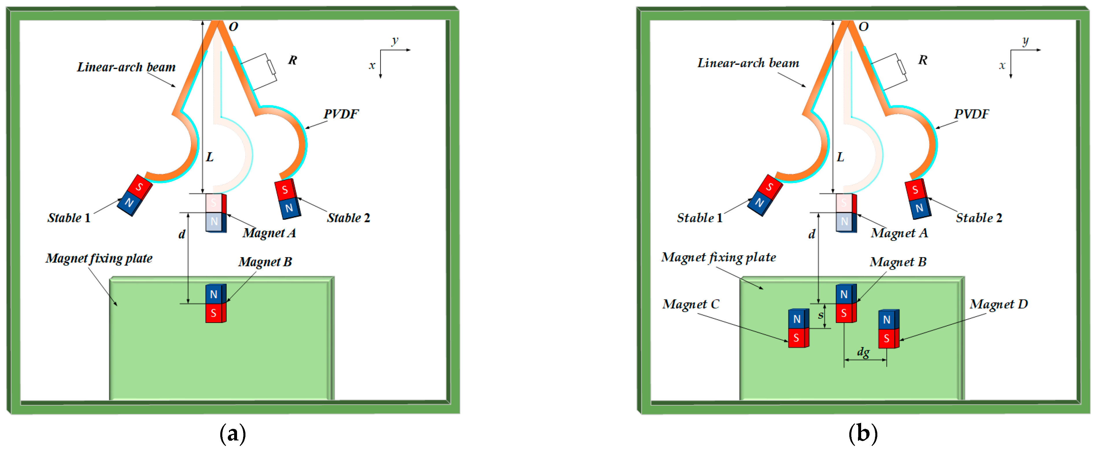
2.1. Structure of the BPEH and IBPEH

Figure 1a is a structural model of the BPEH. BPEH is mainly composed of a base, a magnet fixing plate, a linear-arch composite beam, a magnet, piezoelectric material PVDF, and an external resistor R . One end of the composite beam is fixed on the top of the base, the other end is glued with magnet A, and magnet B is placed on the fixing plate. In particular, magnet A and magnet B maintain a mutually repelling relationship. The total length of the composite beam is L , the height is h S , the width is b s , the arc-shaped radius is R s , and the distance between the centers of magnet A and magnet B is d . Based on this structural model, magnets C and D are added, and magnets C and D are placed symmetrically concerning magnet B, thereby developing the IBPEH, as shown in Figure 1b. All magnets are made of NdFeB. The vertical distance between the centers of magnet B and magnet C is s, and the horizontal distance is d g . Adjusting the positions of magnet C and magnet D properly can change the magnetic force received by magnet A, effectively affecting the nonlinearity of the system.

2.2. Modeling of Restoring Force

This paper uses the dynamometer YLK-10 to measure the restoring force at the end of the composite beam. After fitting the experimental data, the restoring force model diagram of the composite beam, as shown in Figure 2, is obtained. It can be seen from Figure 2 that the structural restoring force F r of the composite beam and its end displacement y show a nonlinear relationship, which is caused by the existence of an arched structure in the composite beam.
The restoring force expression of the composite beam is
F r = α 1 y 3 ( t ) + α 2 y ( t )
in the formula, α 1 = 23894.2927 N/m3, α 2 = 29.3491 N/m3. The restoring force potential energy of the composite beam can be expressed by the above-restoring force integral
U r = F r d y

2.3. Modeling of the Nonlinear Magnetic Model

In this paper, the magnetic dipole theory is used to establish a nonlinear magnetic model. Figure 3 is a diagram of the magnetic force model of IBPEH, in which r i j represents the direction vector of the magnetic force that magnet A receives. As can be seen from the figure, in the IBPEH system, magnet A is subjected to the magnetic force of magnets B, C, and D. For the BPEH system, magnet A is only subjected to the magnetic force of magnet B.
The repulsion force of magnet A by magnet B is
F m 1 = μ 0 M A S A M B S B 4 π   { σ 1 ( d 2 + σ 1 2 ) 3 2 + σ 1 [ ( h a + d ) 2 + σ 1 2 ] 3 2 + σ 2 [ ( d h a ) 2 + σ 2 2 ] 3 2 σ 2 ( d 2 + σ 2 2 ) 3 2 }
The repulsion force of magnet A by magnet C is
F m 2 = μ 0 M A S A M C S C 4 π   { σ 3 ( ( d + s ) 2 + σ 3 2 ) 3 2 + σ 3 [ ( h a + d + s ) 2 + σ 3 2 ] 3 2 + σ 4 [ ( d + s h a ) 2 + σ 4 2 ] 3 2 σ 4 ( ( d + s ) 2 + σ 4 2 ) 3 2 }
The repulsion force of magnet A by magnet D is
F m 3 = μ 0 M A S A M D S D 4 π   { σ 5 ( ( d + s ) 2 + σ 5 2 ) 3 2 + σ 5 [ ( h a + d + s ) 2 + σ 5 2 ] 3 2 + σ 6 [ ( d + s h a ) 2 + σ 6 2 ] 3 2 σ 6 ( ( d + s ) 2 + σ 6 2 ) 3 2 }
For the BPEH system, the magnetic force received by magnet A is F m 1 , while in the IBPEH system, the total magnetic force received by magnet A is
F m = F m 1 + F m 2 + F m 3
In the formula, σ 1 = y ( t ) , σ 2 = y ( t ) + h a θ , σ 3 = y ( t ) + d g , σ 4 = y ( t ) + h a θ + d g , σ 5 = y ( t ) d g , σ 6 = y ( t ) + h a θ d g . The displacement of the free end of the composite beam in the y-axis direction at time t is y ( t ) . M A , M B , M C , and M D are the magnetization of magnets A, B, C, and D, respectively. S B , S C , S D , and S A are the surface areas of magnets B, C, D, and A facing each other, and the deflection angle θ of magnet A and displacement y ( t ) satisfy the following relationship:
θ ( t ) = arctan ( y ( t ) )
where y ( t ) = y ( t ) x .
The potential energy generated between the magnets in the piezoelectric energy harvester system can be obtained by integrating the magnetic force. For the BPEH system, the potential energy generated between the magnets is
U m 1 = F m 1 d y
For the IBPEH system, the potential energy generated between the magnets is
U m 2 = F m d y

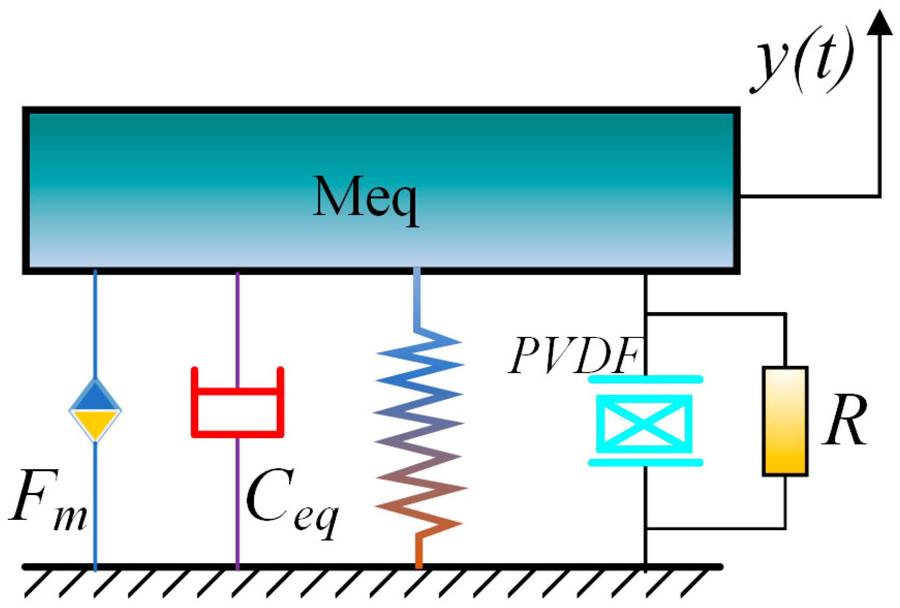
2.4. Dynamic Model of IBPEH

When the composite beam is in the first-order bending vibration mode, the piezoelectric energy harvester obeys the law of energy conservation, and the IBPEH model can be equivalently transformed into a lumped parameter model. Figure 4 is the lumped parameter model diagram of the IBPEH system, where M e q represents the equivalent mass of the system, C e q represents the equivalent damping of the system, R represents the PVDF external resistance, and F m represents the magnetic force received by the magnet A.
According to the equivalent model of lumped parameters of the piezoelectric energy harvester, based on Newton’s second law and Kirchhoff’s law, the nonlinear motion control equation of IBPEH system is established:
M e q y ( t ) ¨ + c y ( t ) ˙ ϑ v ( t ) + F r + F m = γ z ( t ) ¨
ϑ y ( t ) ˙ + C p v ( t ) ˙ + v ( t ) R = 0
where v ( t ) is the voltage across the load resistor R , and y ( t ) is the displacement of the end of the composite beam at time t . z ( t ) = ¨ A c o s ( 2 π f t ) , where z ( t ) is the base vibration displacement, A is the excitation amplitude, and f is the excitation frequency. The parameters of the lumped parameter model of the piezoelectric energy harvester are
ϑ = β ϑ e 31 b ( h p + h s ) L
C p = ε 33 s b L h p
In the formula, A s = b ( h s + 2 h p ) , where ϑ represents the equivalent electromechanical coupling coefficient of the system. e 31 and ϵ 33 s represent the piezoelectric constant and clamping permittivity of the piezoelectric material PVDF, respectively. β ϑ represents the correlation coefficient, and h p represents the thickness of PVDF.

3. Numerical Simulations

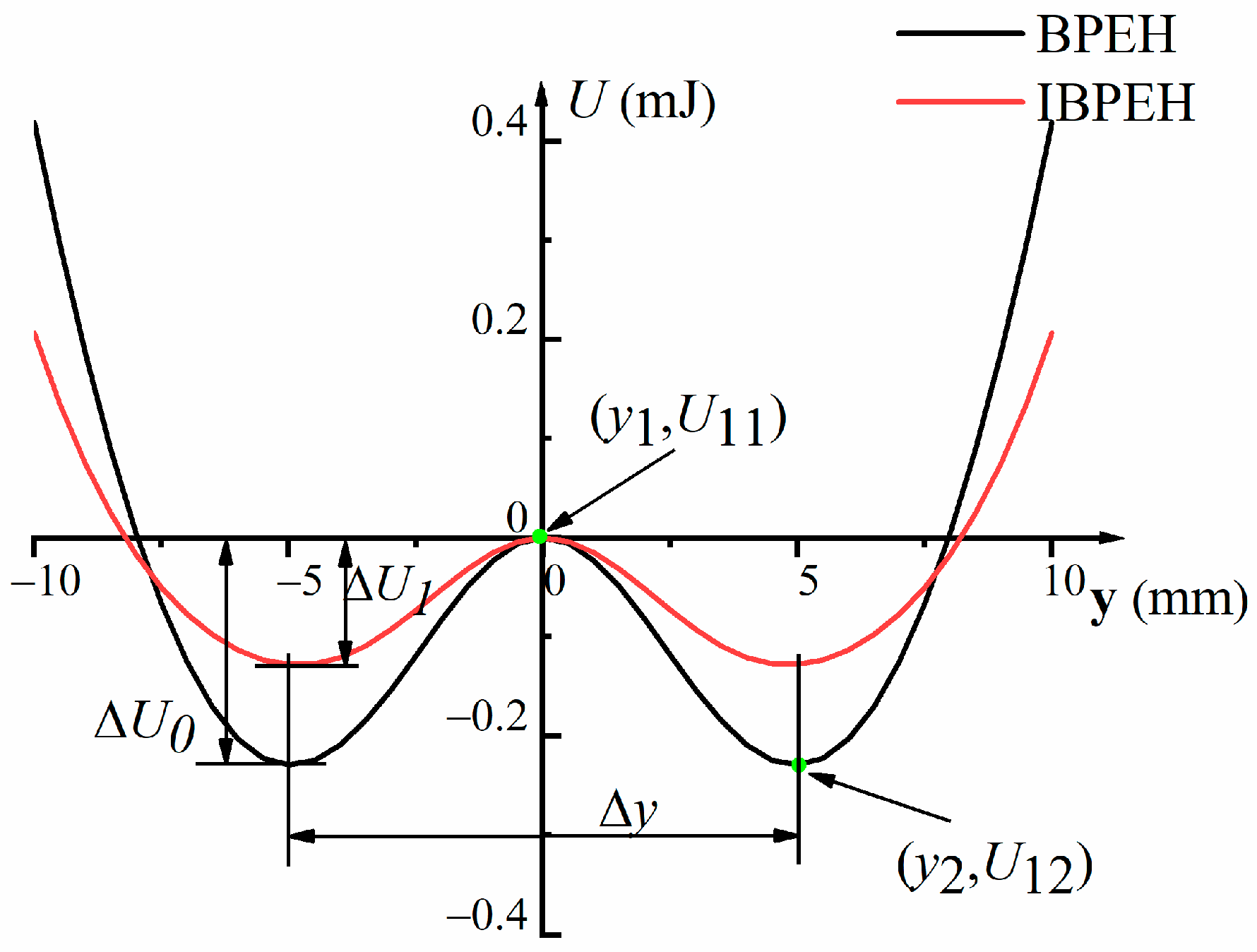
3.1. Potential Energy Analysis of the System

In order to analyze the influence of system parameters on the vibration characteristics of BPEH and IBPEH systems, the potential energy characteristics of the system are first analyzed, and the structural parameters of the BPEH and IBPEH are shown in Table 1.
The depth of the system potential well has a certain influence on the output of the piezoelectric energy harvester. The potential well of the potential energy of the BPEH system is deep at this time, and a large excitation is required to realize the motion between the wells. In this paper, based on the control variable method, by adjusting the positions of magnets C and D, the distance between the BPEH and IBPEH wells are kept the same, and the height of the potential barrier is reduced.
The total potential energy of the BPEH system is U 1 = U m 1 + U r . We selected d = 18 mm and set the highest point of the barrier ( y 1 , U 11 ) and the lowest point of the potential well ( y 2 , U 12 ). From the potential energy curve of the BPEH system, we can obtain
{ U 11 ( y 1 ) = F m 1 ( y 1 ) + F r = 0 U 12 ( y 2 ) = F m 1 ( y 2 ) + F r = 0
Since the potential energy curve of the system is symmetric about the U axis, the values of y 1 and the lowest point y 2 of the potential well on either side are substituted into the following equation:
{ U 21 ( y 1 ) = F m ( y 1 , d g , s ) + F r = 0 U 22 ( y 2 ) = F m ( y 2 , d g , s ) + F r = 0
When the position of magnet C and magnet D is greater than a certain distance from magnet A, magnet A is not affected by the magnetic force of magnet C and magnet D. At this time, the potential energy curves of IBPEH and BPEH systems are consistent, and the equations have countless solutions. Therefore, within a certain range, the initial value is based on the fact that the distances between magnets C and D and magnet B are zero, respectively. We take the values near s = 0 mm and d g = 4 mm as the initial values, use the Newton–Raphson iteration method to solve the nonlinear equation system through MATLAB, and obtain the distance value when the system potential well is the shallowest through verification:
{ s = 2   mm d g = 8.5   mm
Figure 5 shows the potential energy curve of the system when d = 18 mm, s = 2 mm, and d g = 8.5 mm. It can be seen from Figure 5 that the potential well depth of the BPEH system is 0.23 mJ, while that of IBPEH system is 0.12 mJ.

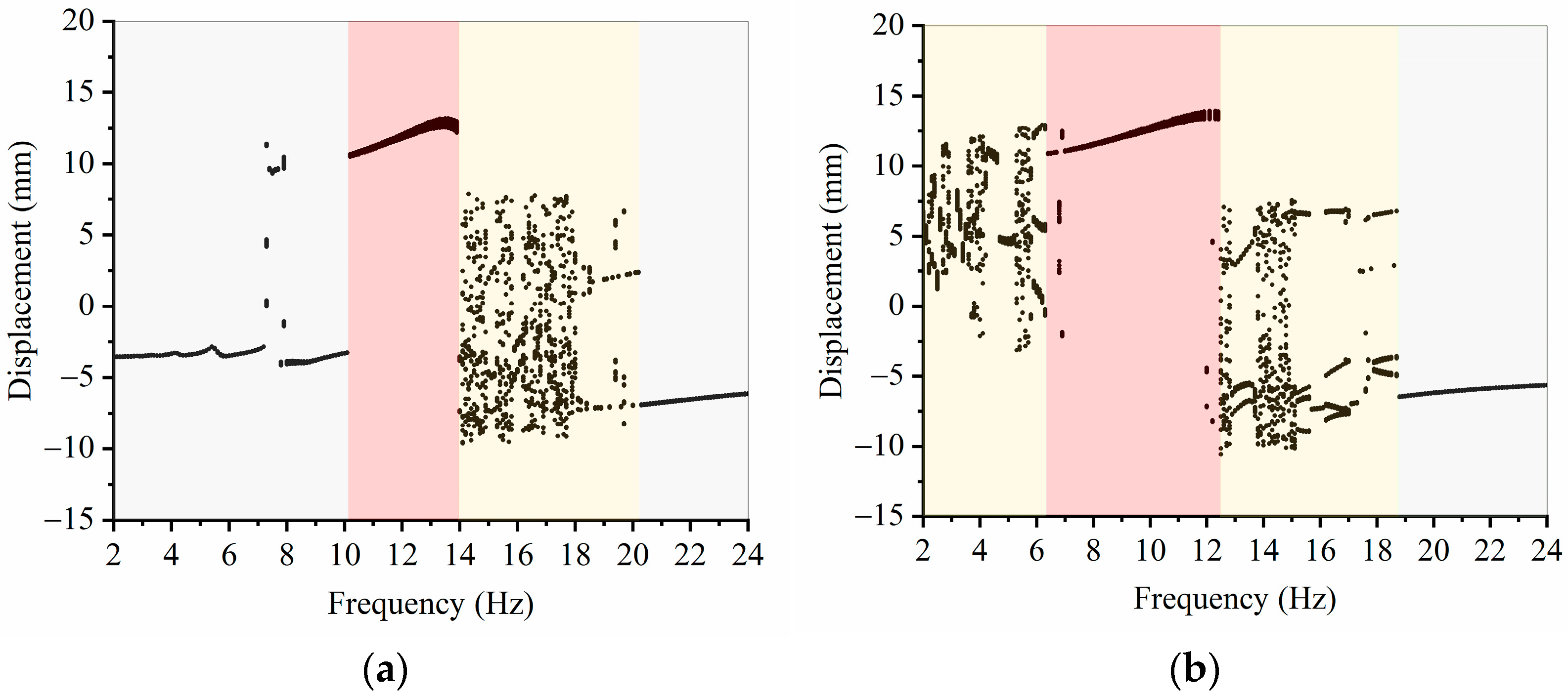
3.2. Influence of Excitation Frequency on Vibration Characteristics

In order to study the output performance of IBPEH and BPEH, we set d = 18 mm, unchanged, and take s = 2 mm and d g = 8.5 mm. Under different excitation frequencies and excitation amplitudes, the Runge–Kutta algorithm is used to numerically solve the dynamic equations, and the vibration characteristics of IBPEH and BPEH are analyzed and compared.
In order to compare and analyze the influence of different excitation frequencies on the response characteristics of BPEH and IBPEH, we set A = 14 m/s2, unchanged, and study the system performance through numerical simulation. Figure 6 shows bifurcation diagrams of BPEH and IBPEH systems with excitation frequency as the parameter. It can be seen from Figure 6 that the change in excitation frequency causes the piezoelectric energy harvester to exhibit diverse motion states. It can be seen from Figure 6a that BPEH experiences small-amplitude intrawell, large-amplitude interwell, chaos, and small-amplitude intrawell various motion states. It can be seen from Figure 6b that IBPEH undergoes complex motion states such as chaos, large-amplitude interwell, chaos, and small-amplitude intrawell oscillation in sequence. To further explore the response output of the piezoelectric energy harvester, the root mean square (RMS) voltage is used for comparison, and the calculation formula is as follows:
U R M S = i = 1 n U i 2 n
In the formula, n is the total number of sampling points, and U i represents the real-time voltage of the i -th sampling point. Sampling in the range of excitation frequency under study, the RMS voltage diagram with excitation frequency as a parameter is obtained in Figure 7.
It can be seen from Figure 6 that when the excitation frequency is in the range of 2–6.3 Hz, the BPEH system performs small-amplitude intrawell oscillation, and the IBPEH system performs chaotic motion. Combined with Figure 7, it can be seen that the RMS voltage produced by IBPEH is larger than that of BPEH, which is caused by the existence of some large-amplitude interwell and small-amplitude intrawell motions in chaotic motion. When the excitation frequency is greater than 6.3 Hz, IBPEH can adapt to this excitation frequency, and the system changes from chaotic motion to large-amplitude interwell periodic motion. Combined with Figure 7b, it can be seen that the RMS voltage produced by IBPEH is improved, while BPEH still maintains small-amplitude intrawell oscillation. When the excitation frequency continues to increase to f = 10.2 Hz, BPEH transitions from small-amplitude intrawell motion to large interwell periodic motion state and the RMS voltage increases significantly, while the IBPEH system continues to maintain large-amplitude interwell periodic oscillation. The operating frequency bandwidth of BPEH is 3.2 Hz in the state of large-amplitude interwell periodic motion, and the operating frequency bandwidth of IBPEH is 6.1 Hz. Continuing to increase the excitation frequency, after the large-amplitude interwell periodic motion of the system ends, the BPEH and IBPEH will decay from the large-amplitude interwell periodic motion state to the chaotic motion state. Because the system is difficult to adapt to the higher excitation frequency, small-amplitude intrawell motion is finally performed. The above analysis shows that before the system realizes large-amplitude motion, the IBPEH behaves in a state of chaotic motion. In this state, the response output of the energy harvester is between the motion state of small-amplitude intrawell and large-amplitude interwell. Compared with BPEH, IBPEH can achieve high-energy yield at a lower excitation frequency, and the operating frequency bandwidth is broadened by 93.55 % .
In order to further explore the influence of the excitation frequency on the output of the piezoelectric energy harvester, keep A = 14 m/s2 unchanged, in the excitation frequency range studied, and take f = 6 Hz, f = 9 Hz, and f = 12 Hz for comparative analysis. Figure 8a,b shows the simulation results of time-domain velocity versus the displacement and voltage–time diagram with the conditions of A = 14 m/s2 and f = 6 Hz, respectively. It can be seen from Figure 8 that the BPEH system performs small-amplitude intrawell periodic oscillation, and the IBPEH system performs chaotic motion. In some periods, the response speed and vibration displacement amplitude of IBPEH are larger. Under this excitation condition, the RMS voltage produced by IBPEH is 16.96 V, while that BPEH is only 2.65 V.
Increase the excitation frequency to f = 9 Hz, and keep A = 14 m/s2 unchanged. Figure 9a,b shows the simulation results of time-domain velocity versus the displacement and voltage–time diagram under this condition. It can be seen from Figure 9 that compared with the small-amplitude intrawell motion state of BPEH, IBPEH can realize a large-interwell periodic motion state, and the response displacement and speed have been greatly improved. In this case, IBPEH can yield a higher voltage, and the RMS voltage is 6.21 times that of BPEH.
Continue to increase the excitation frequency to f = 12 Hz, and keep A = 14 m/s2. Figure 10a,b shows the simulation results of time-domain velocity versus the displacement and voltage–time diagram, respectively. From this figure, it can be seen that both BPEH and IBPEH systems can achieve large-amplitude interwell period motion, and the response displacement and speed of the system have been greatly improved. Compared with BPEH, the RMS voltage of the IBPEH is increased by 23.51 % .
It can be seen from the above analysis that different excitation frequencies have a significant influence on the output efficiency of the piezoelectric energy harvester. Compared with BPEH, IBPEH can adapt to lower excitation frequency and has wider operating frequency bandwidth. Piezoelectric energy harvesters are capable of generating higher and more intensive electrical energy in large-amplitude interwell period motion than in chaotic motion.

3.3. Influence of Excitation Amplitude on Vibration Characteristics

In order to study the influence of excitation amplitude on piezoelectric energy harvesters, under the condition of f = 11 Hz, the influence of different excitation amplitudes on the response produced by IBPEH and BPEH is compared and analyzed. Figure 11 is a bifurcation diagram with excitation amplitude as a parameter. Figure 12 is the RMS voltage diagram. It can be seen from Figure 11 that BPEH and IBPEH can always achieve a large-amplitude interwell motion state with the increase in excitation amplitude. When the excitation amplitude is in the range of 4–9.7 m/s2, it is difficult for the BPEH system to obtain enough energy to eliminate the limitation of the potential well and to oscillate within the well. However, IBPEH presents a state of chaotic motion. Chaotic motion is an irregular motion that is composed of small-amplitude intrawell and large-amplitude interwell. Although it is difficult for IBPEH to maintain high-energy yield, the RMS voltage produced by IBPEH is greater than that of BPEH. Increasing the excitation amplitude to more than 9.7 m/s2, the BPEH maintains a small-amplitude intrawell motion, and the IBPEH system has enough energy to cross the bistable potential barrier to achieve a large-amplitude periodic oscillation; therefore, the piezoelectric energy harvester can continuously produce high energy. Continuing to increase the excitation amplitude, when A = 12.2 m/s2, BPEH can end the small-amplitude intrawell motion state, and the transition realizes the large-amplitude interwell periodic motion state. After that, with the increase in excitation amplitude, the piezoelectric energy harvester will continuously output high energy. Within the analyzed excitation amplitude range, the excitation level threshold for the BPEH system to enter a large-amplitude interwell periodical motion is A = 12.2 m/s2, and when A = 9.7 m/s2, IBPEH can continuously output high energy. Compared with BPEH, the excitation amplitude threshold of IBPEH to achieve a large-amplitude periodic motion state is reduced by 2.5 m/s2.
To further explore the influence of excitation amplitude on the response of BPEH and IBPEH, and keep f = 11 Hz unchanged, based on the above research and analysis, within the range of excitation amplitudes studied, we take excitation amplitudes A = 8 m s 2 ,   A = 11 m s 2 ,   and   A = 14   m / s 2 . When f = 11 Hz and A = 8 m/s2, Figure 13a,b shows the simulation results of time-domain velocity versus the displacement and the voltage–time diagram, respectively. It can be seen from Figure 13a and the bifurcation diagram in Figure 11 that IBPEH is a chaotic motion state under the action of this low excitation level, while BPEH is a small-amplitude intrawell oscillation state, and the response displacement and vibration velocity are much smaller than IBPEH. It can be seen from Figure 13b that the RMS voltage produced by IBPEH is 13.18 V, while that of BPEH is only 2.14 V.
When f = 11 Hz, increase the excitation amplitude to A = 11 m/s2. Figure 14a,b shows the simulation results of time-domain velocity versus the displacement and the voltage–time diagram, respectively. It can be seen from Figure 14a that the BPEH is still in a small-amplitude intrawell motion state, while IBPEH has achieved a large-amplitude interwell periodical motion state, and the response displacement and velocity have been greatly improved. Combined with Figure 14b, IBPEH can continuously produce voltage with high energy, and the RMS voltage produced is 8.07 times that of BPEH. It fully demonstrates the performance of IBPEH that can achieve high efficiency produced under the condition of lower excitation amplitude.
When f = 11 Hz, continue to increase the excitation amplitude to the condition of A = 14 m/s2. Figure 15a,b shows the simulation results of time-domain velocity versus the displacement and the voltage–time diagram, respectively. It can be seen from Figure 15a combined with the bifurcation diagram in Figure 11 that both BPEH and IBPEH are in a state of large-amplitude interwell periodic motion under this excitation condition. Concerning Figure 15b, it can be seen that BPEH and IBPEH can continuously yield voltage with high energy. Compared with BPEH, the RMS voltage produced by IBPEH increased by 24.56%.
For a bistable energy harvesting system, the bistable large-amplitude period oscillation is a motion state in which the energy harvester operates with high efficiency. It can be seen from the above analysis that with the increase in the excitation amplitude, the kinetic energy obtained by the system increases, which will help the piezoelectric energy harvester to achieve a large-amplitude periodic motion state. In addition, compared with BPEH, IBPEH can achieve a large-amplitude periodic oscillation motion state at a lower excitation level, and within the range of excitation amplitude studied, IBPEH can produce a higher voltage.

4. Experimental Validation and Discussion

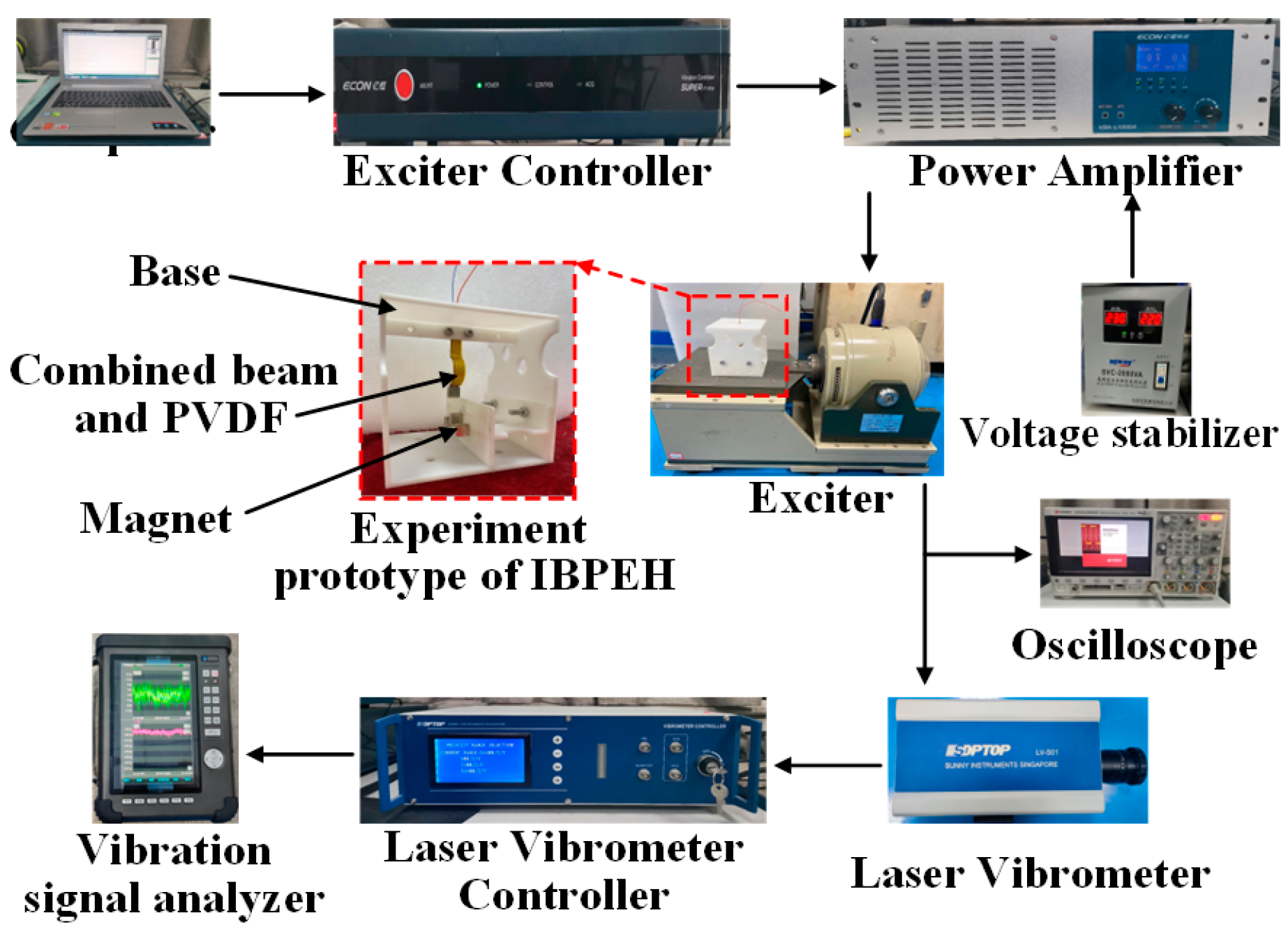
4.1. Experimental Prototype and Experimental Platform

In order to verify the correctness of the simulation results, an experimental prototype is made and an experimental platform is built in this paper. Figure 16 shows the experimental prototype and experimental platform. On this basis, magnet C and magnet D are removed as the BPEH system test platform. The IBPEH system test platform is mainly composed of a computer, voltage stabilizer, exciter controller (VT-9008, ECON, Hangzhou, China), power amplifier (VSA-1000A, ECON, Hangzhou, China), exciter (LT-50ST, ECON, Hangzhou, China), oscilloscope (DSOX3024T, KEYSIGHT, Santa Rosa, CA, USA), laser vibrometer (LV-S01, SDPTOP, Shanghai, China), laser vibrometer controller (LV-S01, SDPTOP, Shanghai, China), and vibration signal analyzer (COCO80X, CRYSTAL, Silicon Valley, CA, USA). The experimental prototype consists of a base, a linear-arch composite beam, a PVDF film, and a magnet. PVDF is evenly bonded to the surface of the composite beam. One end of the composite beam is fixed on the top of the base, and the other end is bonded with magnet A. Magnet B is placed on the fixed end of the base, and magnet C and magnet D are placed symmetrically on both sides of magnet B.
During the experiment, the experimental prototype was installed on the exciter, and the computer control software issued control commands to control the exciter through the exciter controller and power amplifier. In particular, the stable output of the power amplifier was ensured by connecting a voltage stabilizer. The experimental prototype vibrated under the action of the exciter, and the generated voltage data were collected by the oscilloscope. The vibration speed of the composite beam passed through the laser vibrometer and its controller and was finally recorded by the vibration signal analyzer.

4.2. Discussion of Excitation Frequency on Vibration Characteristics

In order to verify the influence of excitation frequency on the performance of the piezoelectric energy harvester, we first set the excitation amplitude to 14 m/s2, and measured the response output characteristics under the conditions of f = 6 Hz, f = 9 Hz, and f = 12 Hz.
Figure 17a–c shows the simulation results of time-domain velocity versus the displacement when A = 14 m/s2 and the excitation frequency is 6 Hz, 9 Hz, and 12 Hz, respectively. Figure 18a–c shows the voltage–time diagrams of A = 14 m/s2 and excitation frequency of 6 Hz, 9 Hz, and 12 Hz, respectively. It can be seen from Figure 17 combined with Figure 18 that the IBPEH system exhibits chaotic motion under the condition of an excitation frequency of 6 Hz, and the RMS voltage produced by IBPEH is 15.42 V. BPEH is small-amplitude intrawell motion state, and the RMS voltage is only 2.32 V. When the excitation frequency is increased to 9 Hz, the IBPEH system can adapt to this frequency and perform large-amplitude interwell motion, and the RMS voltage is 22.32 V, while the BPEH still maintains small-amplitude intrawell motion, and the RMS voltage is only 3.52 V. The RMS voltage of IBPEH is 6.64 times and 6.34 times that of BPEH RMS voltage in turn. Continuing to increase the excitation frequency to 12 Hz, both BPEH and IBPEH show a state of large-amplitude intrawell periodic motion, the RMS voltage produced by BPEH is 20.81 V, and the IBPEH is 27.02 V. Under this excitation condition, the RMS voltage produced by IBPEH is 29.84% higher than that of BPEH, and the experimental results are in agreement with the theoretical analysis results.

4.3. Discussion of Excitation Amplitude on Vibration Characteristics

In order to verify the influence of the excitation amplitude on the performance of the piezoelectric energy harvester, the excitation frequency is set to 11Hz, and the response and output characteristics of the piezoelectric energy harvester were measured under the conditions of A = 8 m/s2, A = 11 m/s2, and A = 14 m/s2.
Figure 19a–c shows the simulation results of time-domain velocity versus the displacement when f = 11 Hz and the excitation amplitude is 8 m/s2, 11 m/s2, and 14 m/s2, respectively. Figure 20a–c shows the voltage–time diagrams when f = 11 Hz and the excitation amplitude is 8 m/s2, 11 m/s2, and 14 m/s2, respectively. Under the excitation conditions of A = 8 m/s2 and A = 11 m/s2, the RMS voltages produced by BPEH are 2.03 V and 3.22 V, while IBPEH is 10.47 V and 25.29 V, respectively. The RMS voltage of the yield of the IBPEH is 5.15 times and 6.85 times that of the RMS voltage of the output of the BPEH in turn. When the excitation amplitude is 14 m/s2, the RMS voltages of the BPEH and IBPEH are 19.77 V and 26.37 V, respectively, and the output of IBPEH is 33.38% higher than that of BPEH. Compared with the simulation results, when the excitation frequency is 11 Hz and the excitation amplitude is 8m/s2, although the IBPEH shows a chaotic motion state in both the simulation and the experiment, the RMS voltage output in the experiment is low, which is why there are more small-amplitude intrawell motions in the experiment, resulting in a less high-energy output of IBPEH. The experimental results show that the response output characteristics of IBPEH are always higher than those of BPEH under different excitation amplitudes, and that IBPEH can achieve sustained high-energy output at lower excitation amplitude.

5. Conclusions

In this work, we designed an improved magnetic coupling bistable piezoelectric energy harvester. The electromechanical coupling dynamics model was established, the nonlinear equation system was solved by the Newton–Raphson iteration method, the distribution of potential wells was improved by adjusting the magnet spacing, and the influences of excitation frequency and excitation amplitude on the vibration characteristics of BPEH and IBPEH were compared and analyzed by numerical simulation. Finally, an experimental platform was designed and built to verify the simulation results. The following main conclusions are drawn from the simulation and experiment:
(1)
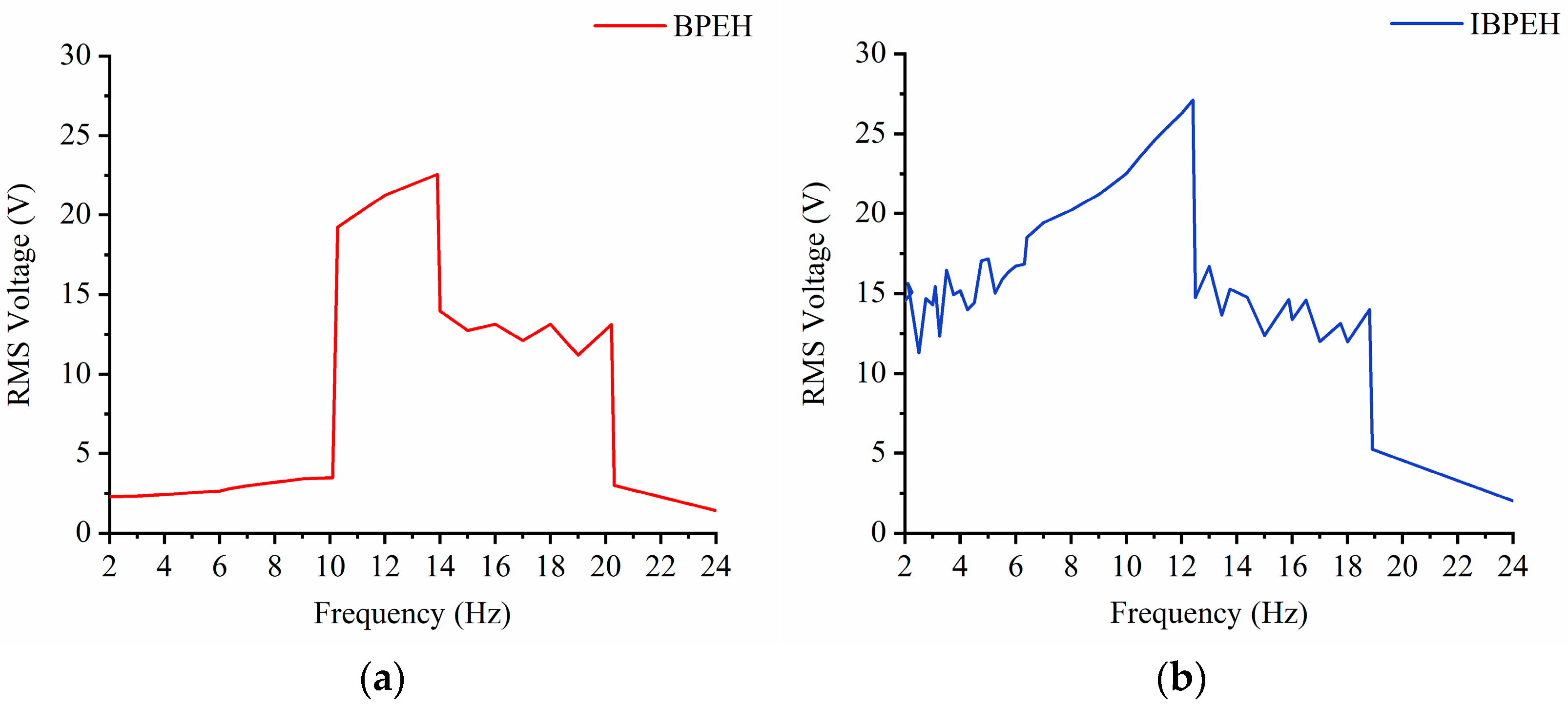
IBPEH has a wider operating frequency bandwidth. In particular, when the excitation amplitude is 14 m/s2, the operating frequency bandwidth of BPEH is only 3.2 Hz, while that of IBPEH is 6.1 Hz, which is a 93.55% improvement.
(2)
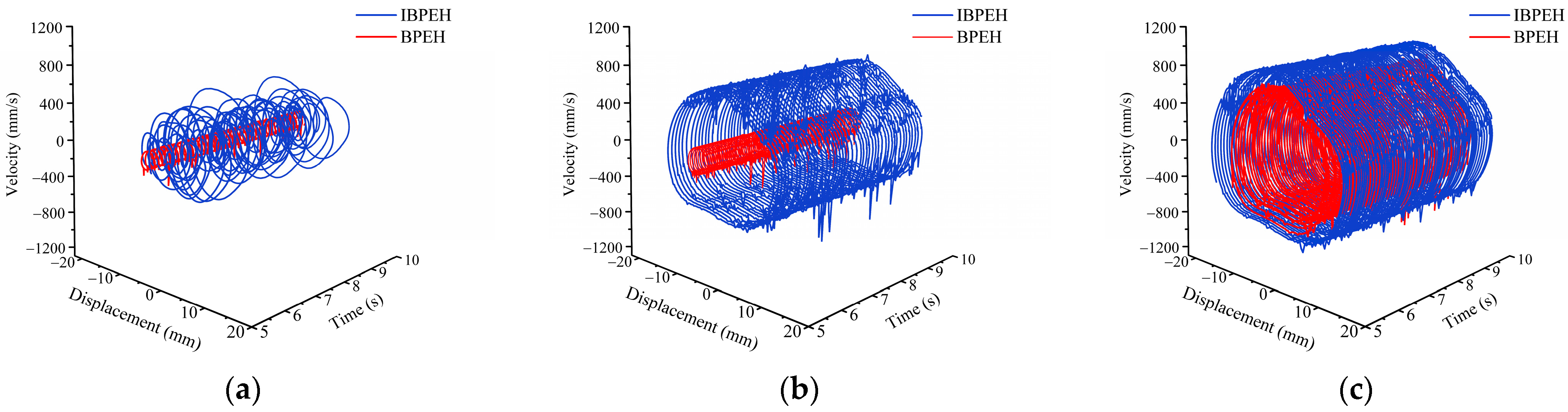
For BPEH, adding magnets and properly adjusting the magnet spacing can make the potential well of the system shallow, and thus optimize the potential well. Compared with BPEH, IBPEH relieves the low excitation threshold to achieve large amplitude cross-hole periodic motion and can achieve dense high-energy output at low excitation amplitude.
(3)
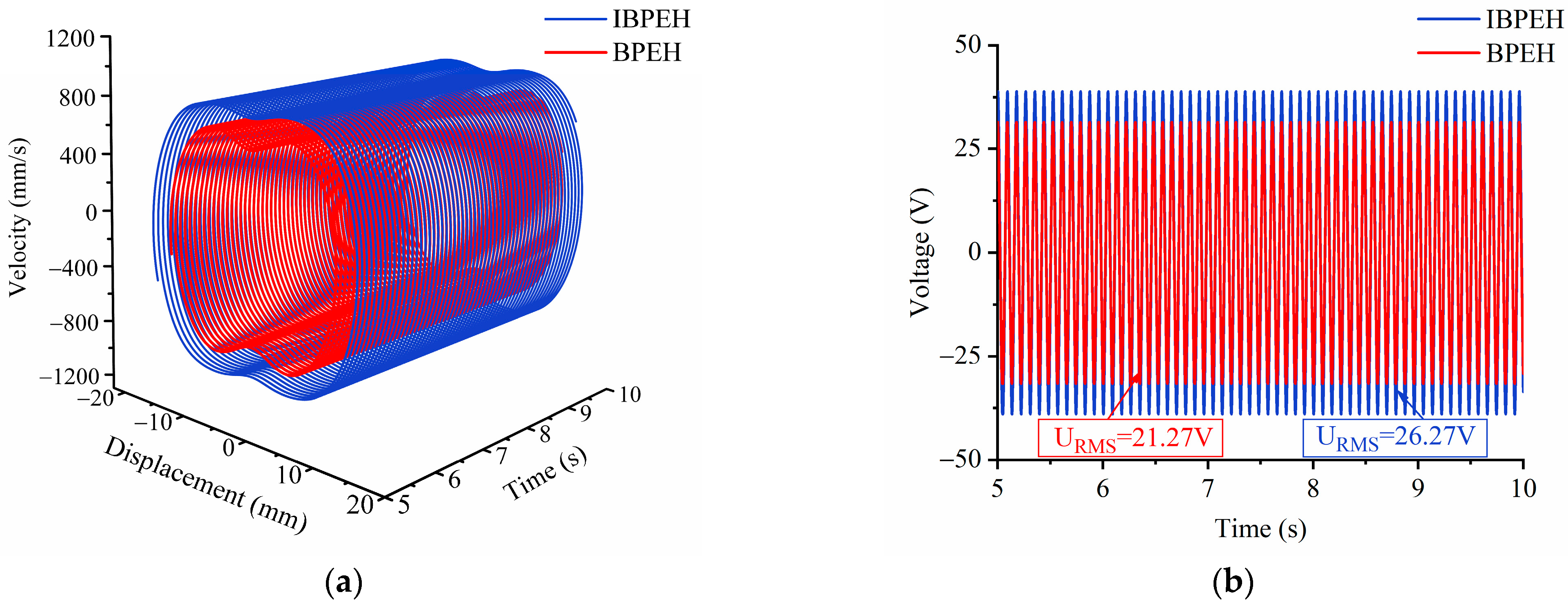
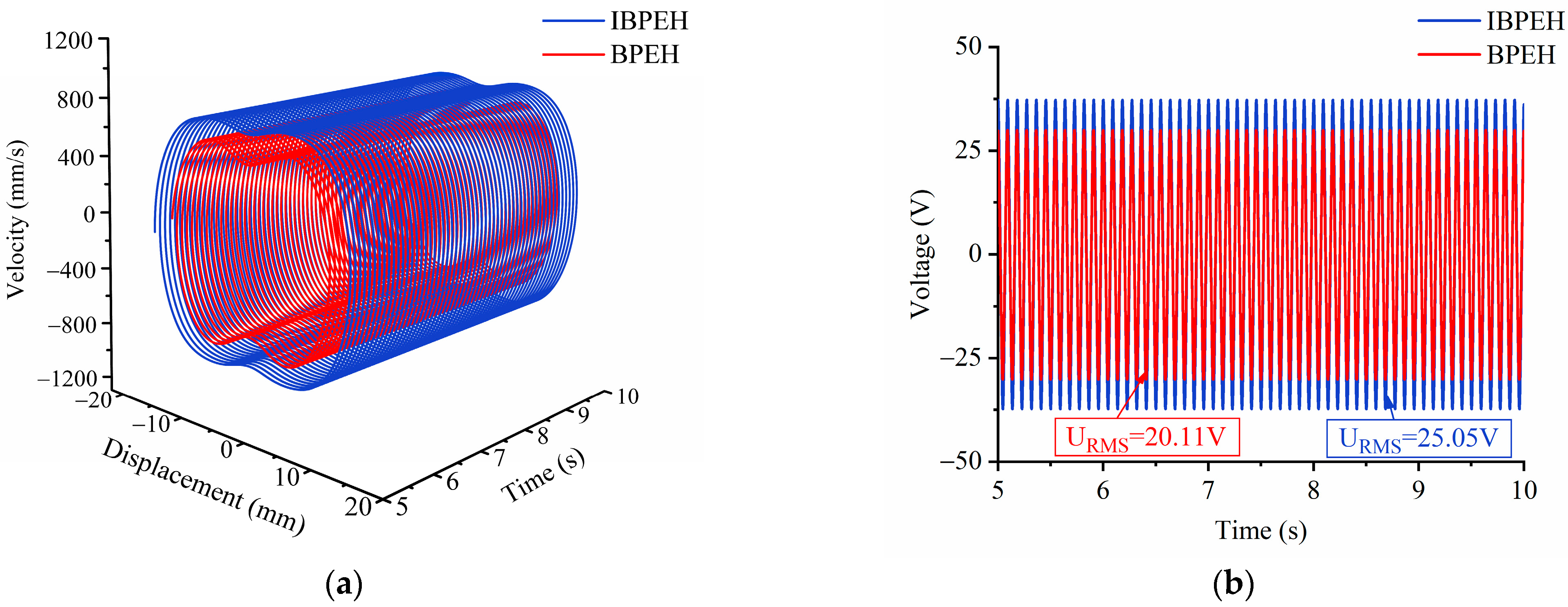
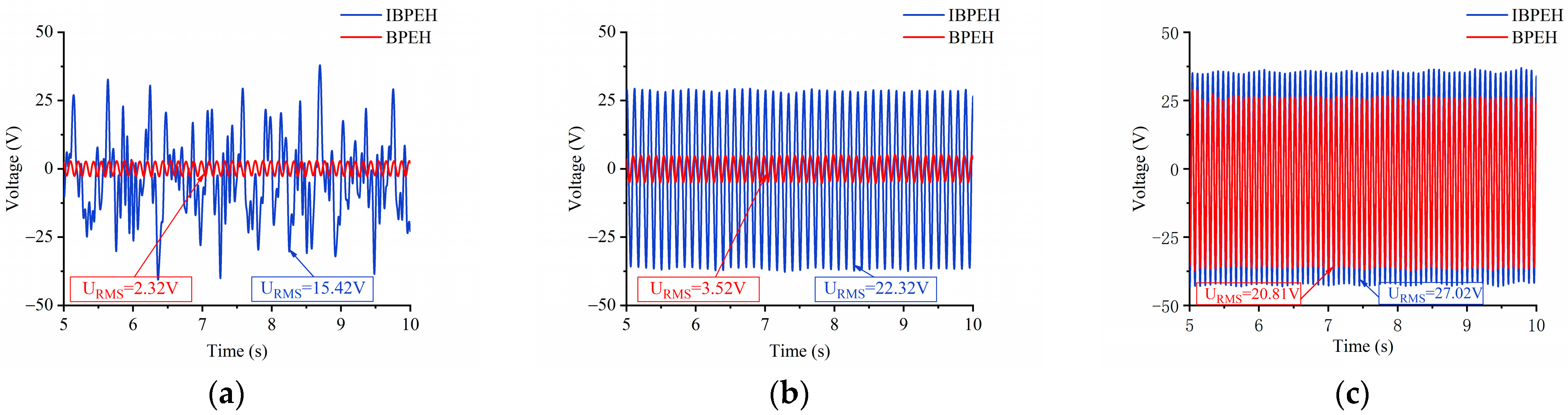
IBPEH can remove the restriction of BPEH potential well depth and improve the power output. In the whole range of excitation frequency and amplitude, the voltage generated by IBPEH is always higher than that of BPEH under the same excitation conditions. This further proves that the change in nonlinearity can affect the collection efficiency of piezoelectric energy harvesters.

Author Contributions

Conceptualization, X.Z. and H.T.; Methodology, H.T.; Software, H.T. and J.P.; Validation, X.C. and H.X.; Writing—original draft preparation, H.T.; Writing—review and editing, F.Z.; Visualization, Y.G.; Supervision, H.T. and M.H.; Project administration, X.Z.; Funding acquisition, X.Z. All authors have read and agreed to the published version of the manuscript.

Funding

This research was funded by the National Natural Science Foundation of China (grant no. 51974228), the Shaanxi Coal Joint Fund Project (grant no. 2021JLM-03), The National Green Manufacturing System Integration Project (grant no. 2017-327), the Shaanxi Innovative Talent Plan Project (grant no. 2018TD-032), and the Key R&D project in Shaanxi (grant no. 2018ZDCXL-GY-06-04).

Institutional Review Board Statement

Not applicable.

Informed Consent Statement

Not applicable.

Data Availability Statement

Not applicable.

Acknowledgments

The authors acknowledge the support from the students Xiaoyu Chen, Mengyao Huang, Fulin Zhu, and Hengtao Xu for their assistance in the modeling and experiments.

Conflicts of Interest

The authors declare no conflict of interest.

References

  1. Muduli, L.; Mishra, D.P.; Jana, P.K. Application of wireless sensor network for environmental monitoring in underground coal mines. J. Netw. Comput. App. 2018, 106, 48–67. [Google Scholar] [CrossRef]
  2. Du, Y.; Zhou, S.; Jing, X. Damage detection techniques for wind turbine blades: A review. Mech. Syst. Signal Process. 2020, 141, 106445. [Google Scholar] [CrossRef]
  3. Tran, N.; Ghayesh, M.H.; Arjomandi, M. Ambient vibration energy harvesters: A review on nonlinear techniques for performance enhancement. Int. J. Eng. Sci. 2018, 127, 162–185. [Google Scholar] [CrossRef]
  4. Daqaq, M.F.; Masana, R.; Erturk, A. On the role of nonlinearities in vibratory energy harvesting: A critical review and discussion. Appl. Mech. Rev. 2014, 66, 4. [Google Scholar] [CrossRef]
  5. Liu, W.; Badel, A.; Formosa, F. A comprehensive analysis and modeling of the self-powered synchronous switching harvesting circuit with electronic breakers. IEEE Trans. Ind. Electron. 2017, 65, 3899–3909. [Google Scholar] [CrossRef] [Green Version]
  6. Mitcheson, P.D.; Miao, P.; Stark, B.H. MEMS electrostatic micropower generator for low frequency operation. Sens. Actuators A Phys. 2004, 115, 523–529. [Google Scholar] [CrossRef] [Green Version]
  7. Arnold, D.P. Review of microscale magnetic power generation. IEEE Trans. Magn. 2007, 43, 3940–3951. [Google Scholar] [CrossRef]
  8. Parinov, I.A.; Cherpakov, A.V. Overview: State-of-the-Art in the energy harvesting based on piezoelectric devices for last decade. Symmetry 2022, 14, 765. [Google Scholar] [CrossRef]
  9. Zhao, X.; Shang, Z.; Luo, G. A vibration energy harvester using AlN piezoelectric cantilever array. Microelectron. Eng. 2015, 142, 47–51. [Google Scholar] [CrossRef]
  10. Shahruz, S.M. Design of mechanical band-pass filters for energy scavenging. J. Sound Vib. 2006, 292, 987–998. [Google Scholar] [CrossRef]
  11. Liu, D.; Al-Haik, M.; Zakaria, M. Piezoelectric energy harvesting using L-shaped structures. J. Intel. Mat. Syst. Str. 2018, 29, 1206–1215. [Google Scholar] [CrossRef]
  12. Syta, A.; Bowen, C.R.; Kim, H.A. Experimental analysis of the dynamical response of energy harvesting devices based on bistable laminated plates. Meacanica 2015, 50, 1961–1970. [Google Scholar] [CrossRef] [PubMed] [Green Version]
  13. Masana, R.; Daqaq, M.F. Electromechanical modeling and nonlinear analysis of axially loaded energy harvesters. J. Vib. Acoust. 2011, 133, 011007. [Google Scholar] [CrossRef]
  14. Mak, K.H.; McWilliam, S.; Popov, A.A. Performance of a cantilever piezoelectric energy harvester impacting a bump stop. J. Sound Vib. 2011, 330, 6184–6202. [Google Scholar] [CrossRef]
  15. Tang, L.; Wang, J. Modeling and analysis of cantilever piezoelectric energy harvester with a new-type dynamic magnifier. ACTA Mech. 2018, 229, 4643–4662. [Google Scholar] [CrossRef]
  16. Ferrari, M.; Bau, M.; Guizzetti, M. A single-magnet nonlinear piezoelectric converter for enhanced energy harvesting from random vibrations. Sens. Actuators A Phys. 2011, 172, 287–292. [Google Scholar] [CrossRef]
  17. Singh, K.A.; Kumar, R.; Weber, R.J. A broadband bistable piezoelectric energy harvester with nonlinear high-power extraction. IEEE Trans. Power Electr. 2015, 30, 6763–6774. [Google Scholar] [CrossRef]
  18. Sun, S.; Cao, S.Q. Analysis of chaos behaviors of a bistable piezoelectric cantilever power generation system by the second-order Melnikov function. Acta Mech. Sinica-PRC 2017, 33, 200–207. [Google Scholar]
  19. Cai, W.; Harne, R.L. Characterization of challenges in asymmetric nonlinear vibration energy harvesters subjected to realistic excitation. J. Sound Vib. 2020, 482, 115460. [Google Scholar] [CrossRef]
  20. Stanton, S.C.; McGehee, C.; Mann, B.P. Nonlinear dynamics for broadband energy harvesting: Investigation of a bistable piezoelectric inertial generator. Physica D 2010, 239, 640–653. [Google Scholar] [CrossRef]
  21. Wang, H.; Tang, L. Modeling and experiment of bistable two-degree-of-freedom energy harvester with magnetic coupling. Mech. Syst. Signal Process. 2017, 86, 29–39. [Google Scholar] [CrossRef]
  22. Abdelkefi, A.; Barsallo, N. Nonlinear analysis and power improvement of broadband low-frequency piezomagnetoelastic energy harvesters. Nonlinear Dynam. 2016, 83, 41–56. [Google Scholar] [CrossRef]
  23. Zhou, Z.; Qin, W.; Du, W. Improving energy harvesting from random excitation by nonlinear flexible bi-stable energy harvester with a variable potential energy function. Mech. Syst. Signal Process. 2019, 115, 162–172. [Google Scholar] [CrossRef]
  24. Rui, X.; Li, Y.; Liu, Y. Experimental study and parameter optimization of a magnetic coupled piezoelectric energy harvester. Appl. Sci. 2018, 8, 2609. [Google Scholar] [CrossRef] [Green Version]
  25. Fan, K.; Tan, Q.; Liu, H. Improved energy harvesting from low-frequency small vibrations through a monostable piezoelectric energy harvester. Mech. Syst. Signal Process. 2019, 117, 594–608. [Google Scholar] [CrossRef]
  26. Lan, C.; Qin, W. Enhancing ability of harvesting energy from random vibration by decreasing the potential barrier of bistable harvester. Mech. Syst. Signal Process. 2017, 85, 71–81. [Google Scholar] [CrossRef]
  27. Zhang, X.; Zhu, F.; Chen, L. Dynamic characteristics and experimental research of linear-arch Bi-stable piezoelectric energy harvester. Micromachines 2022, 13, 814. [Google Scholar] [CrossRef]
Figure 1. Structural models of the BPEH and IBPEH: (a) BPEH; (b) IBPEH.
Applsci 13 00258 g001
Figure 2. Restoring force model of the composite beam.
Applsci 13 00258 g002
Figure 3. Magnetic force model of IBPEH.
Applsci 13 00258 g003
Figure 4. Lumped parameter model of IBPEH.
Applsci 13 00258 g004
Figure 5. Potential energy curve of the system.
Applsci 13 00258 g005
Figure 6. Bifurcation diagram with excitation frequency as parameter: (a) BPEH; (b) IBPEH.
Applsci 13 00258 g006
Figure 7. RMS voltage diagram with excitation frequency as parameter: (a) BPEH; (b) IBPEH.
Applsci 13 00258 g007
Figure 8. Simulation results of time-domain velocity versus the displacement and voltage–time diagram when A = 14 m/s2 and f = 6 Hz. (a) Simulation results of time-domain velocity versus the displacement; (b) voltage–time diagram.
Applsci 13 00258 g008
Figure 9. Simulation results of time-domain velocity versus the displacement and voltage–time diagram when A = 14 m/s2 and f = 9 Hz. (a) Simulation results of time-domain velocity versus the displacement; (b) voltage–time diagram.
Applsci 13 00258 g009
Figure 10. Simulation results of time-domain velocity versus the displacement and voltage–time diagram when A = 14 m/s2 and f = 12 Hz. (a) Simulation results of time-domain velocity versus the displacement; (b) voltage–time diagram.
Applsci 13 00258 g010
Figure 11. Bifurcation diagram with excitation amplitude as parameter: (a) BPEH; (b) IBPEH.
Applsci 13 00258 g011
Figure 12. RMS voltage diagram with excitation amplitude as parameter: (a) BPEH; (b) IBPEH.
Applsci 13 00258 g012
Figure 13. Simulation results of time-domain velocity versus the displacement and voltage–time diagram when f = 11 Hz and A = 8 m/s2. (a) Simulation results of time-domain velocity versus the displacement; (b) voltage–time diagram.
Applsci 13 00258 g013
Figure 14. Simulation results of time-domain velocity versus the displacement and voltage–time diagram when f = 11 Hz and A = 11 m/s2. (a) Simulation results of time-domain velocity versus the displacement; (b) voltage–time diagram.
Applsci 13 00258 g014
Figure 15. Simulation results of time-domain velocity versus the displacement and voltage–time diagram when f = 11 Hz and A = 14 m/s2. (a) Simulation results of time-domain velocity versus the displacement; (b) voltage–time diagram.
Applsci 13 00258 g015
Figure 16. Experimental prototype and experimental platform.
Applsci 13 00258 g016
Figure 17. Simulation results of time-domain velocity versus the displacement when A = 14 m/s2: (a) f = 6 Hz; (b) f = 9 Hz; (c) f = 12 Hz.
Applsci 13 00258 g017
Figure 18. Voltage–time diagram when A = 14 m/s2: (a) f = 6 Hz; (b) f = 9 Hz; (c) f = 12 Hz.
Applsci 13 00258 g018
Figure 19. Simulation results of time-domain velocity versus the displacement when f = 11 Hz: (a) A = 8 m/s2; (b) A = 11 m/s2; (c) A = 14 m/s2.
Applsci 13 00258 g019
Figure 20. Voltage–time diagram when f = 11 Hz: (a) A = 8 m/s2; (b) A = 11 m/s2; (c) A = 14 m/s2.
Applsci 13 00258 g020
Table 1. Structural parameters of BPEH and IBPEH.
ParameterSymbolValueUnit
Substrate layer
Density ρ s 8300 kg/m3
Arc-shaped radius R s 10 × 10 3 m
Length L 40 × 10 3 m
Height h s 2 × 10 4 m
Width b s 8 × 10 3 m
PVDF
Density ρ p 1780 kg/m3
Length L p 40 × 10 3 m
Height h p 1.1 × 10 4 m
Width b p 8 × 10 3 m
Magnet
Mass m 0 3.8 × 10 3 kg
Length l a , l b , l c , l d 4 × 10 3 m
Height h a , h b , h c , h d 10 × 10 3 m
Width w a , w b , w c , w d 10 × 10 3 m
Magnetization strength M a , M b , M c , M d 5.5 × 10 5 A/m
Vacuum permeability μ 0 4 π × 10 7 H/m
Disclaimer/Publisher’s Note: The statements, opinions and data contained in all publications are solely those of the individual author(s) and contributor(s) and not of MDPI and/or the editor(s). MDPI and/or the editor(s) disclaim responsibility for any injury to people or property resulting from any ideas, methods, instructions or products referred to in the content.

