Article

Joule Heating and Arc-Fault-Induced Electrical Fires for Commercial-Grade Copper and Brass in Low-Voltage Electrical Systems

by
Sittichai Wangwiwattana
* and
Koike Yoshikazu
Shibaura Institute of Technology, Tokyo 135-8548, Japan
*
Author to whom correspondence should be addressed.
Appl. Sci. 2022, 12(9), 4710; https://doi.org/10.3390/app12094710
Submission received: 29 March 2022 / Revised: 1 May 2022 / Accepted: 4 May 2022 / Published: 7 May 2022

Abstract

:
Electrical fires are usually caused by contact heating, for which the mechanism of heat accumulation is currently not well understood. Previous studies done by many researchers were able to recognize the pattern of the electrical waveform, but the actual mechanism behind such phenomenon is still a mystery. This research focuses on electrical plugs and sockets made from copper and electrical brass, which are the main components where unsupervised electrical fires often occur due to mechanical wear and electrical breakdown. We performed experiments using commercial-grade replacement electrical sockets and plugs made primarily to be compliant with Japan Industrial Standards. Oxides of the materials were formed by subjecting the samples to variable amounts of current and repeatedly making and breaking contact to create an electrical discharge. The copper(I) oxide that formed due to electrical discharge was found to have intrinsic semiconductor properties that played a critical role in electrical fires involving copper components. Poor contacts exhibited distinct behavior, such as contact vibration which also exacerbated the deterioration. From these findings, we concluded that any contact surface made of copper or a copper alloy may have a greater risk of starting an electrical fire than other types of material when a certain arcing condition is met.

1. Introduction

The majority of house fires in Japan are caused by electrical fires [1]. Electrical safety has been greatly improved by electrical fire protections, such as the GFCI outlet, but the number of fire incidents has not steadily decreased, but rather has fluctuated without exhibiting any significant improvement [2]. In this paper, we will divide household electrical fires into two main categories. The first is those caused by human error, which includes fires that are due to reasons such as a faulty setup or product mishandling. The second category includes fires that are caused by mechanical or electrical breakdown from prolonged usage and those caused by faults acquired during the manufacturing process. These types of electrical fires are difficult to prevent due to the nature of the breakdown involved, which is inherently unpredictable. In addition to manufacturing defects, faults can also be induced by occasional product mishandling.

Glowing Condition and Arc Fault

In this paper, we will focus on series-type low-current arc faults in commercial electrical appliances [3]. It is well known that a worn-out electrical socket or plug has the possibility of causing a fire due to poor contact conditions. The glowing condition occurs when electrical current flows between two contact points that are composed either of different or the same materials. The contact point accumulates heat from the Joule heating effect, itself a result of contact resistance. Contact resistance is the actual resistance at the contact point or, if contact is small, the conducting spot between two points. In classical contact theory, as it relates to electrical fires, the amount of heat that is generated by contact resistance is proportional to the amount of current passing through the contact point [4]. If the contact point has a high resistance, then more power will be dissipated at the contact area, eventually causing the material to glow “red hot”. The material around the glowing area is composed of molten oxides of the original construction material, such as iron oxides for the screw and nut fixtures and copper oxides for the wire terminals. High temperatures at the contact points can create a fire hazard if any flammable materials are near them when they begin to glow and become molten: wire housing insulation, which is usually made from wool and cloth, is just such a material. The heat from the glowing area can also conduct outward, thus heating the whole conducting area and creating secondary glowing conditions near the primary one. The glowing connection phenomenon frequently happens in areas with a loose connection near the electrical terminal and is even more common when the construction material for the terminal is less conductive, such as the steel used for the screws. Terminals with steel screws can be found in older residential areas, the same areas where electrical fires are most likely to occur. Newer electrical terminals in modern buildings are made of electrical-grade brass or copper to reduce contact resistance, which likewise reduces the chance of initiating a glow. However, electrical contacts made from copper or an alloy of copper are responsible for glowing connections more so than any other type of connector, a point which will be discussed further in this paper. The primary hazard associated with glowing connections is the subtlety of the phenomenon. A device or an appliance could have a glowing connection but appear as though it were functioning normally. The only way to detect this phenomenon is to monitor the current that is delivered to the load and look for an abnormal level of current draw. Such monitoring is used only in places such as factory settings where the environment contains something that could be a fire hazard (wheat dust, saw dust, etc.). When the critical temperature is reached, both the terminal and any electrical device connected to it will still function normally, but the high temperature from the glow can damage the insulation and the area around the affected point, thus creating a fire hazard.
In addition to contact resistance, a glowing condition can also be caused by an arc fault. Arc faults can be divided into two main categories: series arc faults and parallel arc faults. In most circumstances, arc faults occur on high-voltage switching boards where the voltage between ground and the live wire is high enough that the air between the two points of contact becomes ionized, resulting in an electrical discharge. This discharge can release an extreme amount of energy, to the point where the heat at the arcing point can damage the insulation and the support structure. In a high voltage setting, such as that at a power station, the arc-fault discharge is capable of inflicting severe burns within a fraction of a second to people who are exposed to it without protective gear. The low-voltage arc-fault mechanism is similar to its high-voltage counterpart, but the discharge is not energetic enough to produce large arcs that can cause burns to objects in the surrounding environment. However, even though the low-voltage discharge is not intense enough to melt and break open the electrical contact, it can still be hazardous. The low-power electrical discharge can continuously accumulate heat at the affected area, resulting in the build-up of oxide layers. The oxides created by an arc fault can then induce glowing conditions, which eventually lead to an ignition when the temperature becomes higher than the flashpoint of the material surrounding the contact point. This includes the plastic housing and insulation that surrounds old electrical wires. The first type of arc fault is called short-circuit arcing, which is categorized as a type of parallel arc fault. This phenomenon occurs when the live electrical wire is exposed due to mechanical failure or the degradation of the insulating and protective layers surrounding it. The live wire is then loosely connected to either a hot-to-neutral or a hot-to-ground cable. If two wires are tightly connected, then the connection can generate a substantial amount of heat proportional to the amount of current at the load center, which is enough to cause an extreme fire hazard. On the other hand, if two wires are loosely connected, then it is possible to obtain what is known as a “sputtering arc”. This type of parallel arcing is a low-current arcing between two wires that can generate enough heat to damage the insulation around the affected area. Once the majority of the insulation is damaged, it opens a path through which a high amount of current can flow. Modern electrical breakers can reliably detect this type of arcing, greatly reducing the fire hazard risk associated with this phenomenon. The second type of arc fault is called a series arc fault. It is a relatively new phenomenon and the least understood of the arc-fault types. Series arcing occurs when a broken wire arcs to itself in a colinear fashion. The electrical spark caused from the broken contact of the wire is perceived as an arc. This kind of arcing is relatively low-current compared to a parallel arc fault. However, the heat generated by it is sufficient to damage or destroy the surrounding insulation and to ignite any flammable substances near the arcing area. In a controlled experiment testing series arcing at sea level and at atmospheric pressure, according to the Paschen curve, the lowest breakdown voltage is 327 V, which is higher than the electrical sources used by household devices. Having a lower breakdown voltage is possible, but the distance between the two gaps must be extremely small and the wires must be passing the original AC signal. Since the voltage in an alternating current is not constant, neither is the arcing. DC series arcing is often not a concern as a potential fire hazard since high-voltage DC systems are not widely used in residential areas. In factories, high-voltage DC systems are usually well monitored, and they tend to have protections built into them to prevent damage to machines.
It is difficult to detect a fire hazard from a low AC voltage, such as the 100 V power sources that are widely employed in Japanese consumer products, and to predict when and where it will happen. Electrical devices that change their current draw based on temperature can falsely identify a hazard as a glowing connection. Placing a temperature sensor near the electrical contact point is not a reliable solution since a glowing connection can happen at any point where there is a loose connection. This includes places within the machine or within the construction wall where a wire has broken. Series arc faults are also difficult to detect since a device has to be able to distinguish differences in the RF (Radio Frequency) component of the waveform between normal operation and operation after an arc fault has developed. There are many electrical devices that have an RF component that is similar to that of a series arc fault, which is what makes this differentiation a difficult task. The type of contact present at the arc fault’s location also has a major effect on the pattern of the RF waveform, and this too must be sorted out by the detection system. This paper will elaborate further on the mechanisms behind series arc faults in copper-based connections.

2. Previous Work by Other Researchers

Since electrical appliances first became common in households, researchers have conducted many studies on glowing conditions and arc faults. One such study by Meese and Beausoliel [4] in 1976 investigated glowing electrical contacts by passing an electrical current through the point of contact between two conducting materials. The contact point produced a substantial amount of heat, enough to enable it to emit a glow. They also made some observations of the electrical discharge at the affected area. Hereafter, an electrical discharge from loosely connected parts will be referred to as an arc fault. An arc fault usually occurs at points where contacts are loosely attached. Meese and Beausoliel also claimed that their results were applicable for 120 V, the amount found in a nominal voltage setting. Research done by Hagimoto [5,6] demonstrated that an arc fault cannot be sustained unless there is some external perturbation to the contact surface. Oxides of the contact material are formed by the high temperatures in the glowing portion of the contact spot. Shea [7] reported that the oxide bridge that is formed between the two contacts is the primary cause of the glowing condition. The contact material from which the oxides are formed is usually copper based. Stainless steel, which is used for the nuts and bolts that tie down electrical contacts, and cast iron rarely create oxides. To sustain a glowing contact, there must be oxygen present in the environment to oxidize the copper material and create an insulation bridge. Oxidized copper materials include copper(II) oxide, CuO, and copper(I) oxide, Cu2O. Cu2O behaves as a semiconductor. When glowing connections occur, CuO behaves as an insulator and increases the overall contact resistance. Since a high resistance at the contact surface produces Joule heating, the temperature there increases around the oxide bridge. Eventually, the temperature of Cu2O reaches a point where the contact material is able to oxidize, thus causing more oxides to be generated at the contact point. Subsequently, the overall contact resistance decreases as the temperature rises. The research done by Urbas [8] has shown that a current below 1 Arms can create glowing connections in commercial-grade household switches where the appliance is constantly perturbed by vibrations. He concluded that the push-in connection between the wire and the switch must be poor to create a glowing connection in the switch and suggested that the actual contact points in commercial-grade switches be plated with silver. We can deduce from Urbas’ setup that the glowing connection in his work is an electrical discharge from two conductors making and breaking contact, thus creating an electrical arc. This type of electrical arc can heat the point of contact to its glowing temperature. Glowing conditions for this type of contact do not follow classical electrical contact theory [9,10,11]. This theory is mostly concerned with a single type of conductive layer at a conduction spot with a continuous flow of electrons. In actuality, the electron flow is more likely to bounce off conductors in small contact spots. As a result, the actual electron flow produces Sharvin resistance, which then increases the overall contact resistance. Other researchers [12,13,14] were able to replicate a low voltage arc fault and devised a method to detect the phenomenon from the pattern of the waveform. They were able to recreate with a specific setup with various types of electrodes. However, the waveforms of the low voltage arc fault from each type of the material are different [15,16]. Shea [16] deduced that the voltage waveform of copper-based material is the same where other types of contact, such as steel, are to be grouped differently, but they were still not able to create an explanation of why the two types have different behavior. Therefore, the actual mechanism behind such a phenomenon is still inconclusive.
We will investigate the mechanics of series arc faults with commercial plugs and sockets as a baseline for the material.

3. Characteristic of Glowing Connections and Arc Faults

A common misconception is that glowing connections and arc faults are similar. However, an arc fault is a continuous electrical discharge between two conducting points [17] that produces heat from an ionizing spark, whereas a glowing connection consists of purely resistive heating [18]. At a very high current, glowing connections can emit a bright light and be misidentified as an arc fault. As mentioned earlier, arc faults themselves can induce a glowing connection. In this research, we will focus on arc faults that can lead to a glowing connection or both phenomena at the same time.

Producing Low-Voltage Arc Faults

Based on previous studies by many researchers, there are specific environmental parameters and conditions for the contact point that must be met. If any of the conditions listed below are not present in the testing environment, then the arc fault will be much more difficult to produce. The voltage and current used in the experiment were set to common household levels, as suggested by Urbas [8] and Hagimoto [5]. The glow can occur at low power, but the energy released from it and the arcing is high enough to ignite the surrounding material. The conditions for the production of the oxide bridge are as follows:
  • The atmosphere must contain oxygen so that the copper-based material can be oxidized.
  • The conductor material should be of a type that has a high melting point and that behaves as an electrical insulator after it has been oxidized.
  • The two electrical conductors must have a poor contact spot so as to increase contact resistance [19] and Sharvin resistance, thus creating the Joule heating effect.
  • The electrical current passing through the contact spot should not be higher than the current capacity of the oxide or the contact spot, and it should not be lower than the threshold where electrical discharge becomes impossible for certain gap distances between the conductors.
To sustain an arc fault, an oxide bridge must be created from the conductor material.

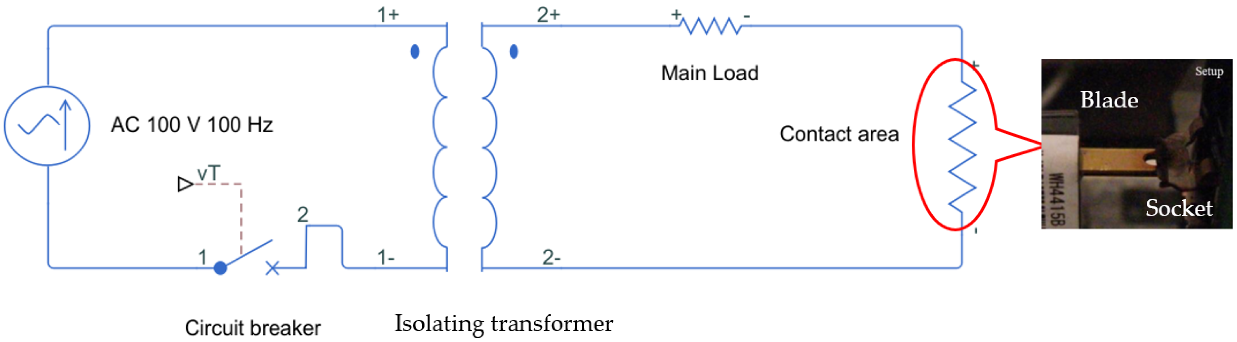
4. Experiment Configuration

The experiment configuration is presented in Figure 1. The electrical socket and electrical plug blade are held tightly in place by a movable clamper. To produce the initial oxide bridge, an electrical current is passed through the conductor with a resistive load. By continuously making and breaking contact between the conductors, small arcing is produced and creates oxide patches at the contact area. Contact wear on the surface is accelerated by arcing [20] when the conductor makes contact. A small amount of mass is lost with each arcing instance, creating holes and an uneven contact surface. In an AC system, where the electrical current fluctuates between two peak values, if the conductors make contact at the zero-crossing point, then the discharge arc may not be present. To reliably monitor the lifetime of an electrical socket, the action of making and breaking contact must be performed at the peak voltage level of the AC system where the discharge is the most energetic.

Experiment Samples and Current Source

The samples used for the electrical socket were made of Electrolytic Tough Pitch (ETP) Copper (C1100), which is a type of oxygen-free copper. This type of copper is commonly used as an electrical conductor due to its purity and low oxygen content. It also exhibits high ductility and high impact strength, qualities that increase its lifetime as a contact surface. Another material used as a conductor in the experiment was an unknown alloy of electrical brass. It adhered to the Japanese Industrial Standards for electrical receptacles (JIS C 8303:2007) and is shown in Figure 2. The experiment used an isolation transformer to protect the building fuse. However, due to the parasitic inductance of the transformer, the voltage and current were out of phase. The load used in the experiment was a set of wire-wound resistors with resistances of 12 Ω, 25 Ω, and 100 Ω, respectively. All of the resistors exhibited insignificant parasitic inductance at 100 V and 50 Hz. The justification for choosing resistors with these values is that they are typical of what is commonly found in electrical appliances that are used in household environments. The current is measured using a clamper probe, and the voltage is measured between the two contact points. An oscilloscope is used to measure the voltage drop when an electrical discharge is present. Previous studies made use of a movable electrode. The two electrodes then repeatedly make and break contact until the oxide bridge is formed. To accelerate the creation of the oxide bridge, a small amount of copper oxide powder is created by putting the same type of copper used in electrical sockets into a furnace. The copper socket part was heated to 800 °C for 30 min. The black residue on the surface of the treated copper was then removed and pulverized into a fine powder. This powder was then applied to the electrical discharge spot of the contact surface. The heat from the electrical discharge is sufficient to melt the fine copper oxide powder and form the oxide bridge. Once a glowing state is achieved, the oxide bridge can leech copper from the surrounding area to form a larger bridge.

5. Arcing Characteristics

Once the process explained in the above section has been fulfilled. The contact points glow into a bright spot with visible arcing. The arcing strength largely depends on the amount of current passing through the contact point, but the size of the oxide bridge and the glow filament path, as mentioned by Shea, can also dictate the energy released as heat. We grouped the characteristic of the glowing and arcing connection into three sections. The waveform of the connection when an arc fault is present, the vibration at the contact point, and the relation of the arcing process to the temperature.
The arc was observed using a CASIO EX-F1 high-speed camera set to its highest recording setting of 1200 frames per second. Arcing from all types of contact exhibited a pulsating discharge at twice the frequency of the AC system. In the DC system, as shown in Figure 3, the arc fault normally discharged from one end of the electrode to the other in a continuous manner. The possible explanation for the pulsating discharge in the AC system is that each period of the waveform contains two voltage peaks, one positive and one negative. Once the breakdown voltage is reached, the air around the arc spot is ionized, and electrons move through the air with much lower resistance. However, the actual causes of the arc flashes at every specific interval were not caused by the breakdown voltage between the air gap—this will be explained in the “Relation to Temperature” subsection and the discussion section. The voltage drop is shown in Figure 4 at the point where arcs occur. The waveform of the current was measured using a current probe (A622, Tektronix Inc., Beaverton, OR, USA). The current waveform exhibits a small “shoulder” where the current level remains constant. The arc duration varies from 13 to 16.5 ms, and it is extinguished when the zero-crossing point is reached. The arc resumes once the current approaches its peak and crest. The experiment was performed at 1 A, 4 A, and 8.33 A, respectively.

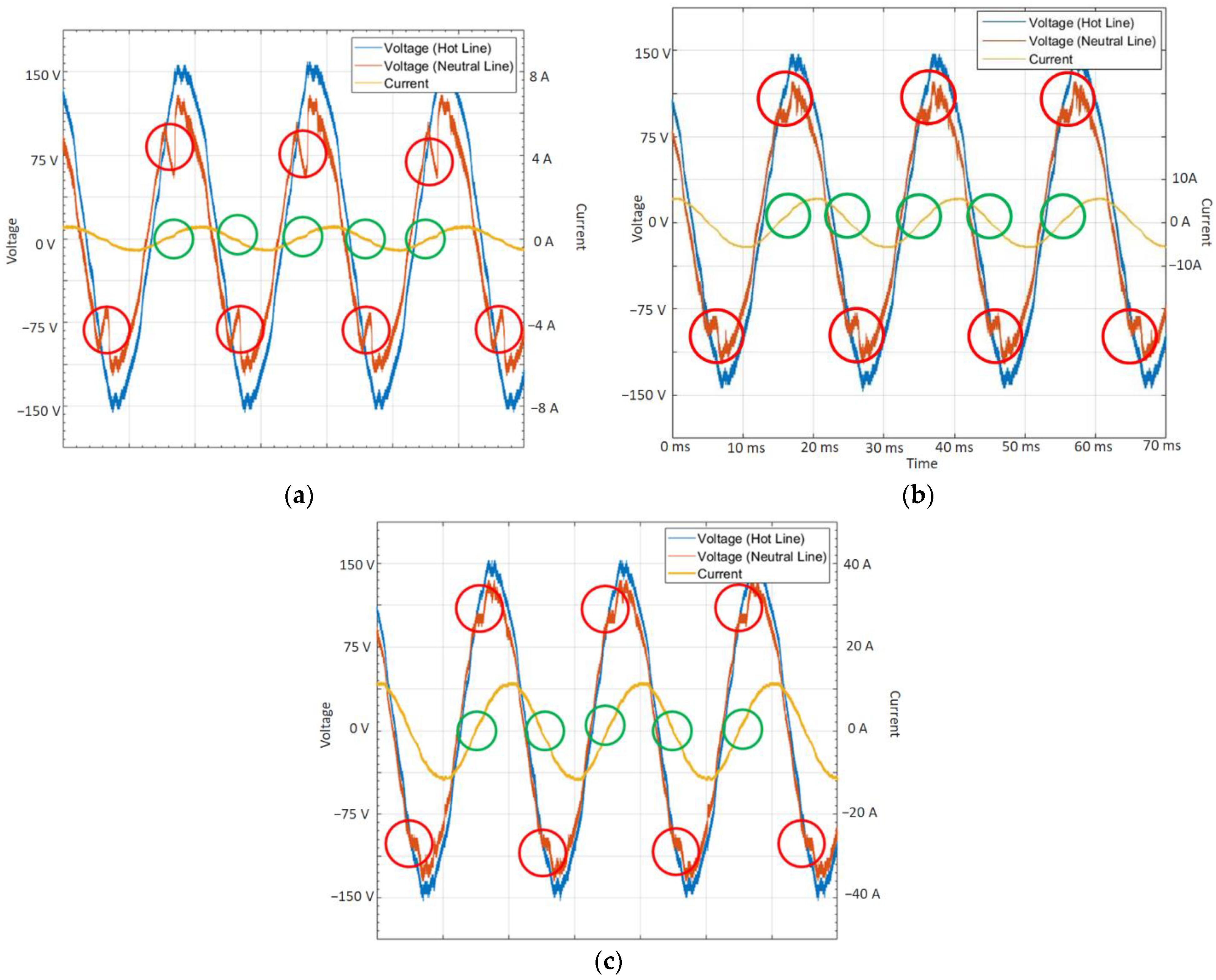
5.1. Characteristics of the Waveform for the Glowing Connection

As shown in Figure 4a, at 1 A, the waveform exhibits a voltage drop for both probes near the zero-crossing of the current. At 8.33 A and 4 A, as shown in Figure 4b,c, respectively, the waveform exhibits the same pattern as the lower-current setup but with a significantly lower voltage drop. The waveform for the higher-current setup also exhibits much more distortion at the zero-crossing of the current. It has been suggested that the voltage drop as shown in red circle results from the inability of current to pass through the oxide bridge at the zero-crossing point. Therefore, the circuit is cut open momentarily which creates a current shoulder as shown in Figure 4 in the green circle. The power flow resumes once the current level is high enough. The waveform at the top of the voltage drops and at the current shoulder was also observed. The neutral line exhibited a large voltage drop compared to the voltage from the hot line. The power that was to be delivered into the main load was instead dissipated at the contact point and could be recorded by a simple detection device for observing arc fault incidents at low voltages.

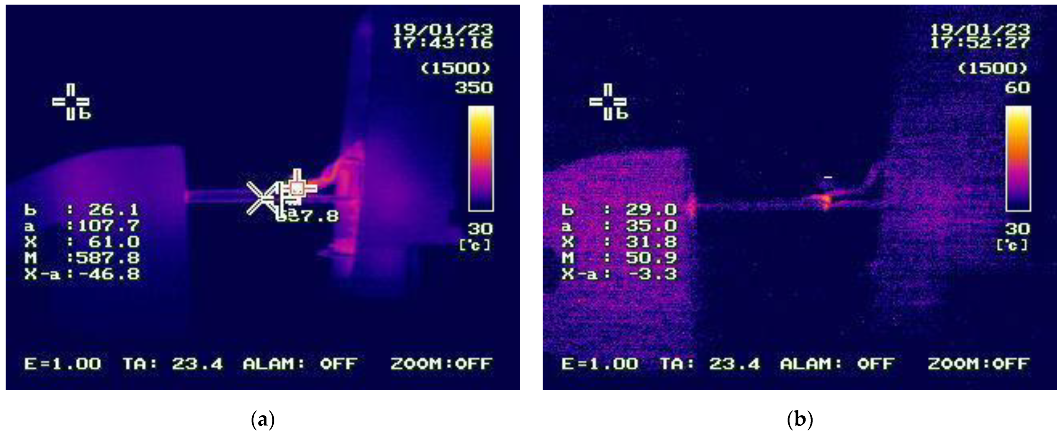
5.2. Relation to Temperature

The resistance of the contact area was measured between two contact points at various temperatures using an infrared thermal imaging camera (G100EX, Nippon Avionics Co., Ltd., Yokohama, Japan) and is shown in Figure 5. The current flow between the two contact points was set to 8.33 A. The reason for using a current of 8.33 A is that the generated arc fault is usually energetic enough to increase the temperature at the contact point beyond 600 °C. At 600 °C, the heat is sufficient to generate copper oxide. At a lower current setting, such as 4 A, the arc fault is not sporadic enough to raise the temperature of the contact area above 600 °C. The temperature data was taken from room temperature at 21 °C up to the highest temperature possible. Upon initiation of the arc-fault state, the temperature rapidly increased to around 130 °C then gradually rose to 700 °C. Two multimeter probes (FLUKE 8846A Precision Digital Multimeter, Fluke Co., Ltd., Washington, DC, USA) were inserted to measure the resistance between the two points of contact. The results show that when the temperature between the two points of contact was higher, the resistance was lower than it was at room temperature. This is shown in Table 1. The oxide bridge at the contact points acts as an electrical insulator. When the contact was perturbed while making and breaking the contact arc, the arc fault became self-sustaining. When the contact point reached a temperature at and above 520 °C, the resistance fluctuated between 1 kΩ and less than 100 Ω. Therefore, in this experiment, the resistance value was measured for temperatures ranging from 21 °C to 520 °C. It was observed that at around 300 °C, the resistance value fell to the kiloohm range, indicating that there were semiconductor properties at the contact point. The semiconductor properties of copper oxide, which has a negative temperature coefficient, are well understood. The results we gathered indicate that current flow may be facilitated by the semiconductor properties of the contact surface.

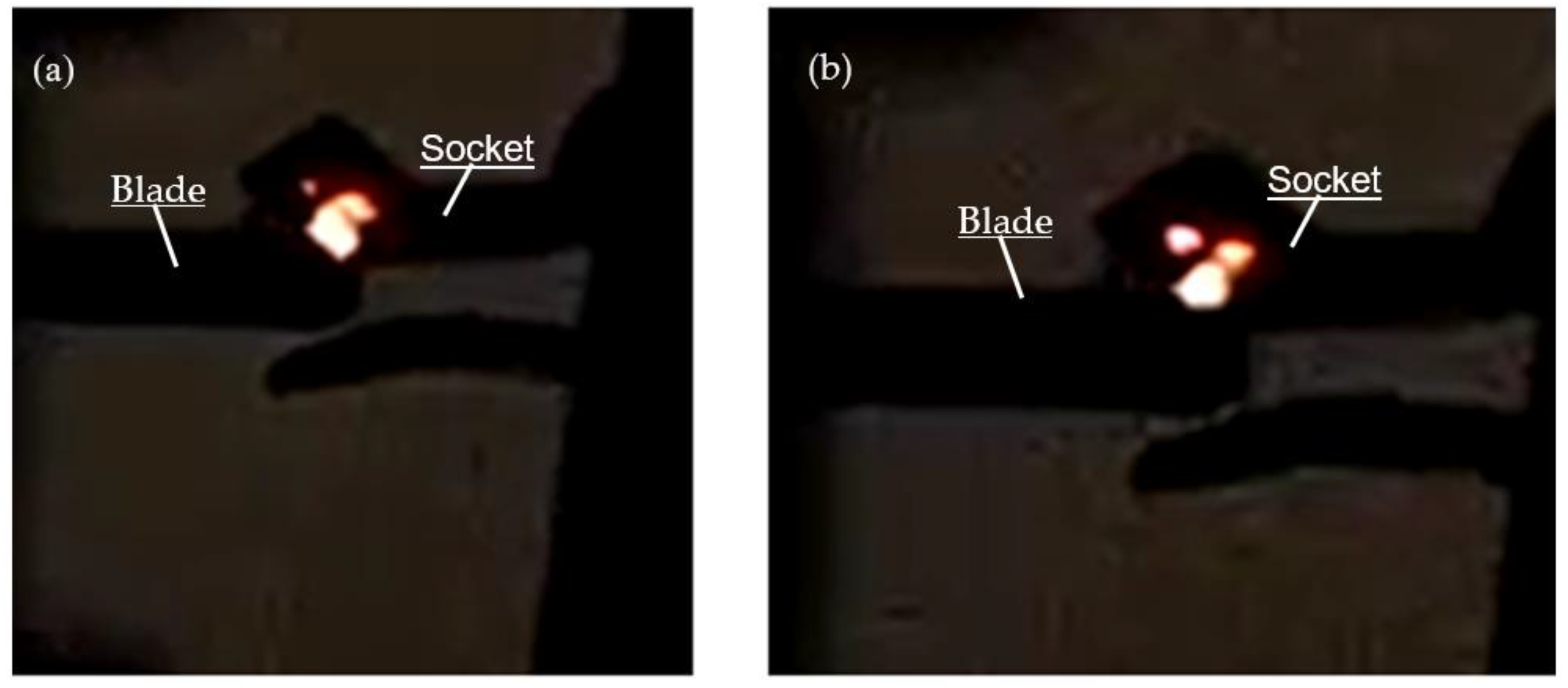
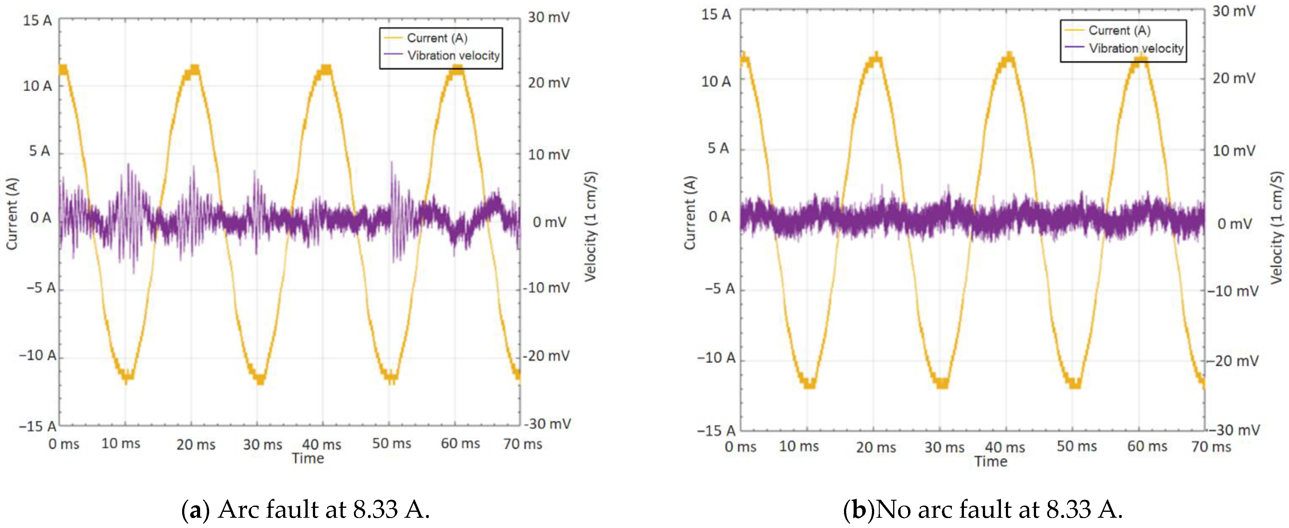
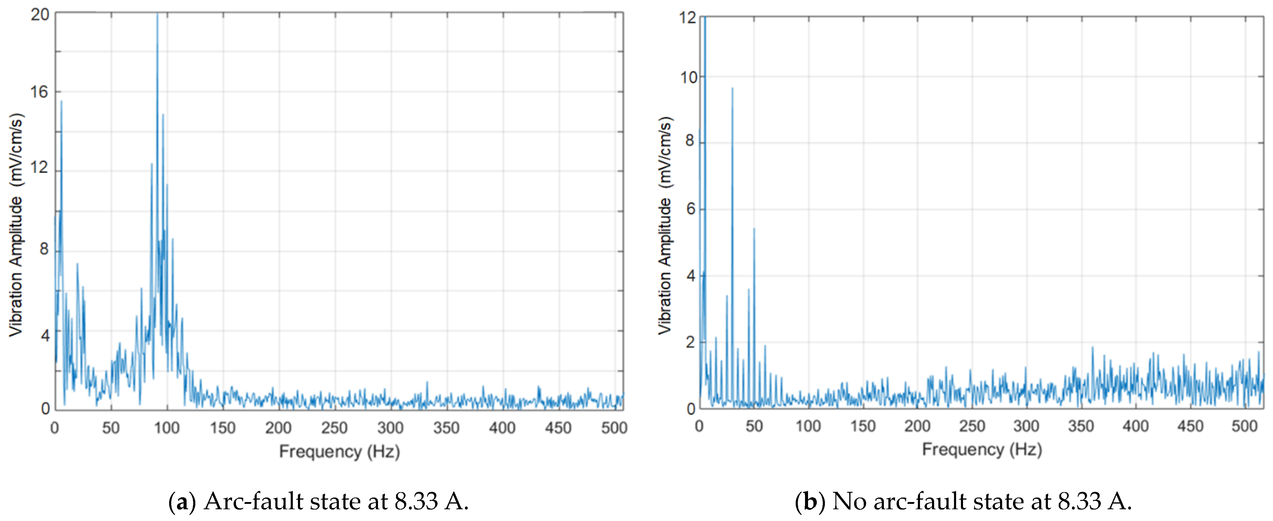
5.3. Arcing Vibration

When an arc fault occurs, sound is emitted from the contact point of the plug. The vibration at the contact point was measured using a laser Doppler vibrometer (LV-1300, Ono-sokki Co., Ltd., Yokohama, Japan). Although it is hard to create identical arc-fault states, the vibration at the contact point is always observed. Typical results for this measurement are shown in Figure 6. According to these results, the vibration strength is directly proportional to the amount of current that is being passed through the contact spot. However, the variations in the vibration velocity every period are due to the contact surface area. The vibration strengthens when the arcing condition is present at the connection. Figure 7 shows an FFT analysis of the vibration velocity waveform in Figure 6. It also shows that the contact area will vibrate at twice the frequency of the AC. The strongest vibration would occur every time the current reached the zero-crossing point. Vibrations that are caused by poor contact may not be present in the direct current setup due to its continuous discharge. This phenomenon is poorly understood due to the difficulties presented by the microscopic scale of the contact area in it. We were unable to make measurements of the thickness, width, and girth of the contact point. The amount of current that flows through that small contact area will need to be simulated by computer analysis in future research. Given what we know, there are two possible explanations for the vibration phenomenon. The first explanation attributes it to thermal expansion, and the second explanation attributes it to the electromagnetic field change within the small contact area. We will explain the thermal expansion explanation first. The strength of the vibration in the arc fault depends on multiple factors. The first factor is the amount of heat that is generated and dissipated in the contact area. It is directly proportional to the amount of current that passes through the contact spot and the resistance of the contact area. The second factor is the thickness of the oxide at the location where the current is flowing. As mentioned earlier, the arc fault extinguishes itself or is dimmed at every zero-crossing point and near the points where the current shoulder and voltage drop are observed. It is assumed that the temperature at the affected area initially decreases but then increases again when the arc fault is reinitiated. If the heat affects a large enough area, it may cause thermal expansion when the arc state flashes up. Consequently, the arc state will increase the size of the affected area and push away both contacts. When the arc extinguishes itself at the zero-crossing point, the affected area shrinks in size due to the reduction in temperature. This back-and-forth expansion may also initiate a secondary making or breaking of the contact spark, and it can also reinitiate the arc-fault state if the temperature falls too low near the new contact area. This means that in every arc-fault state, even if the setup is running with the same amount of current, the vibration strength would not be equal in every experiment due to the changes in the contact area. To replicate the vibration strength, the size of the copper oxide bridge at the contact area must always be the same. The other explanation is the electromagnetic field change. A sudden field change is experienced when the arc extinguishes and reignites and is similar to rapidly switching the circuit on and off. This produces an electromagnetic force that can attract the two contacts together.

6. Discussion

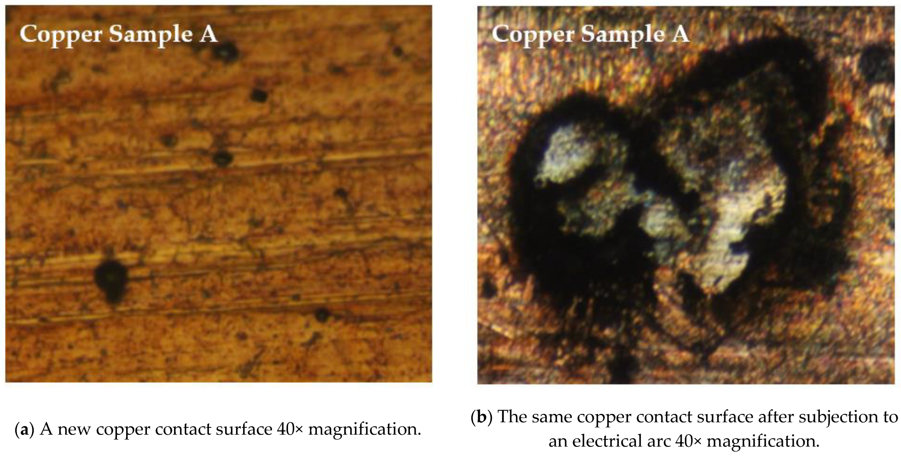
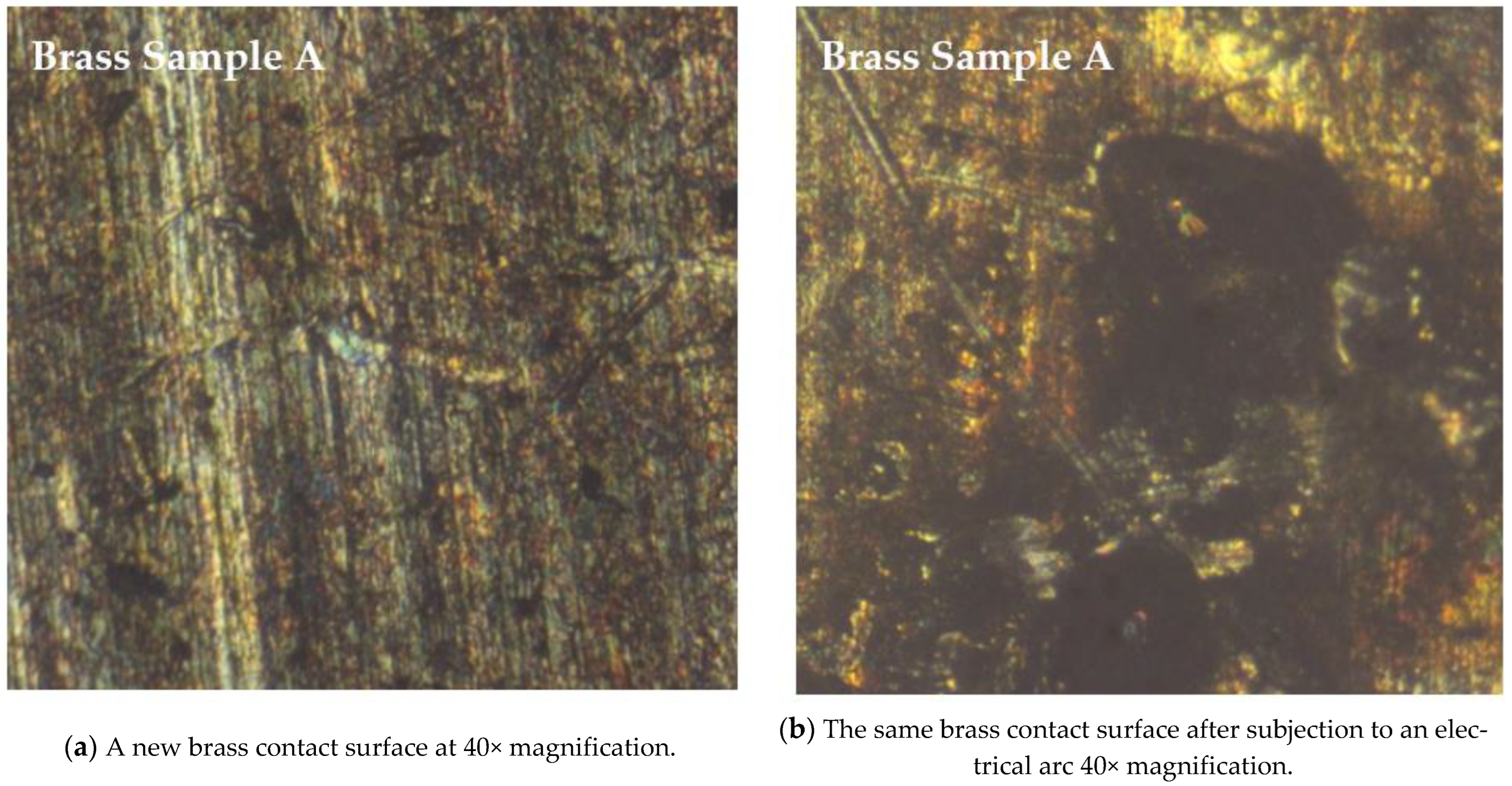
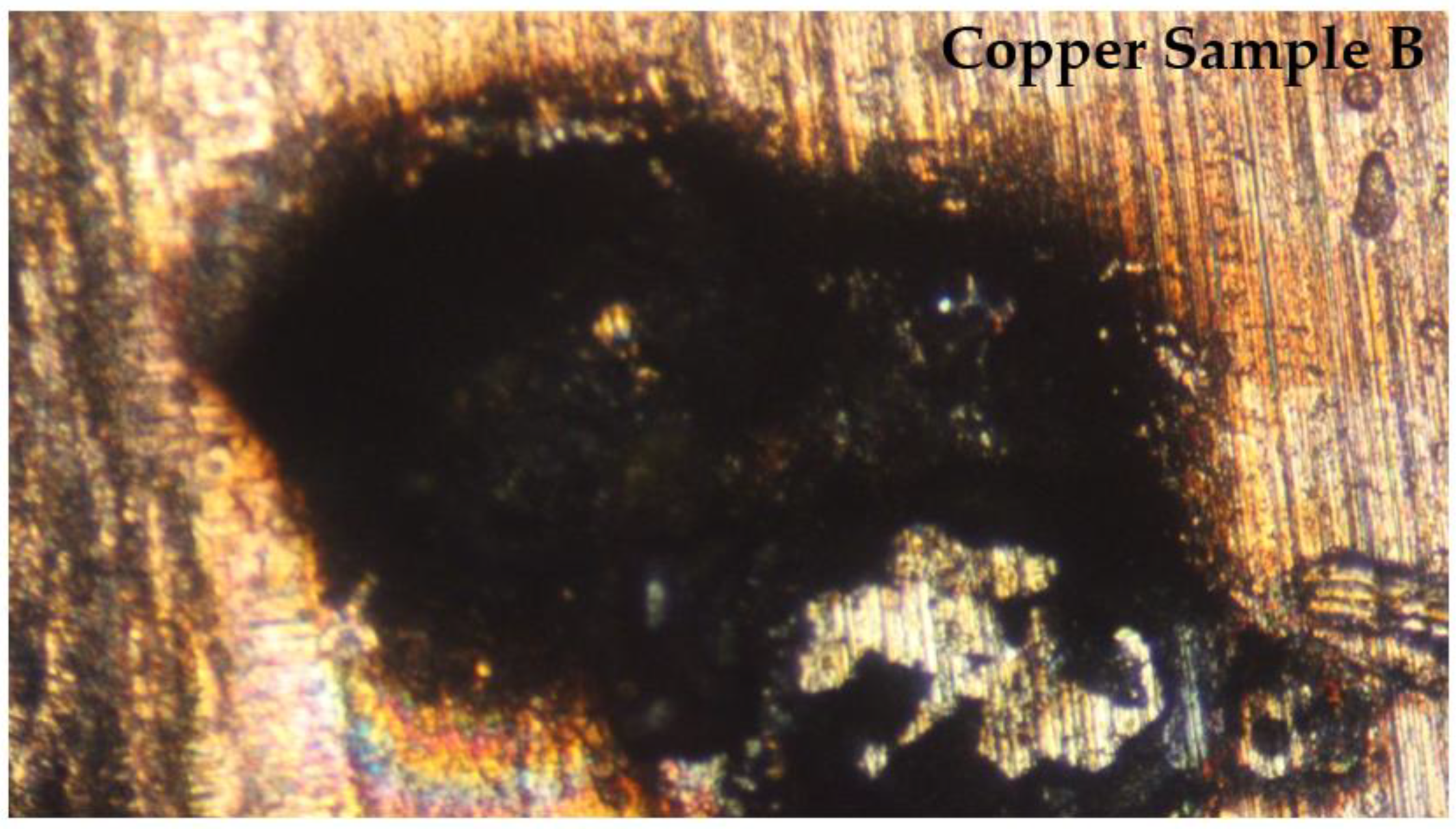
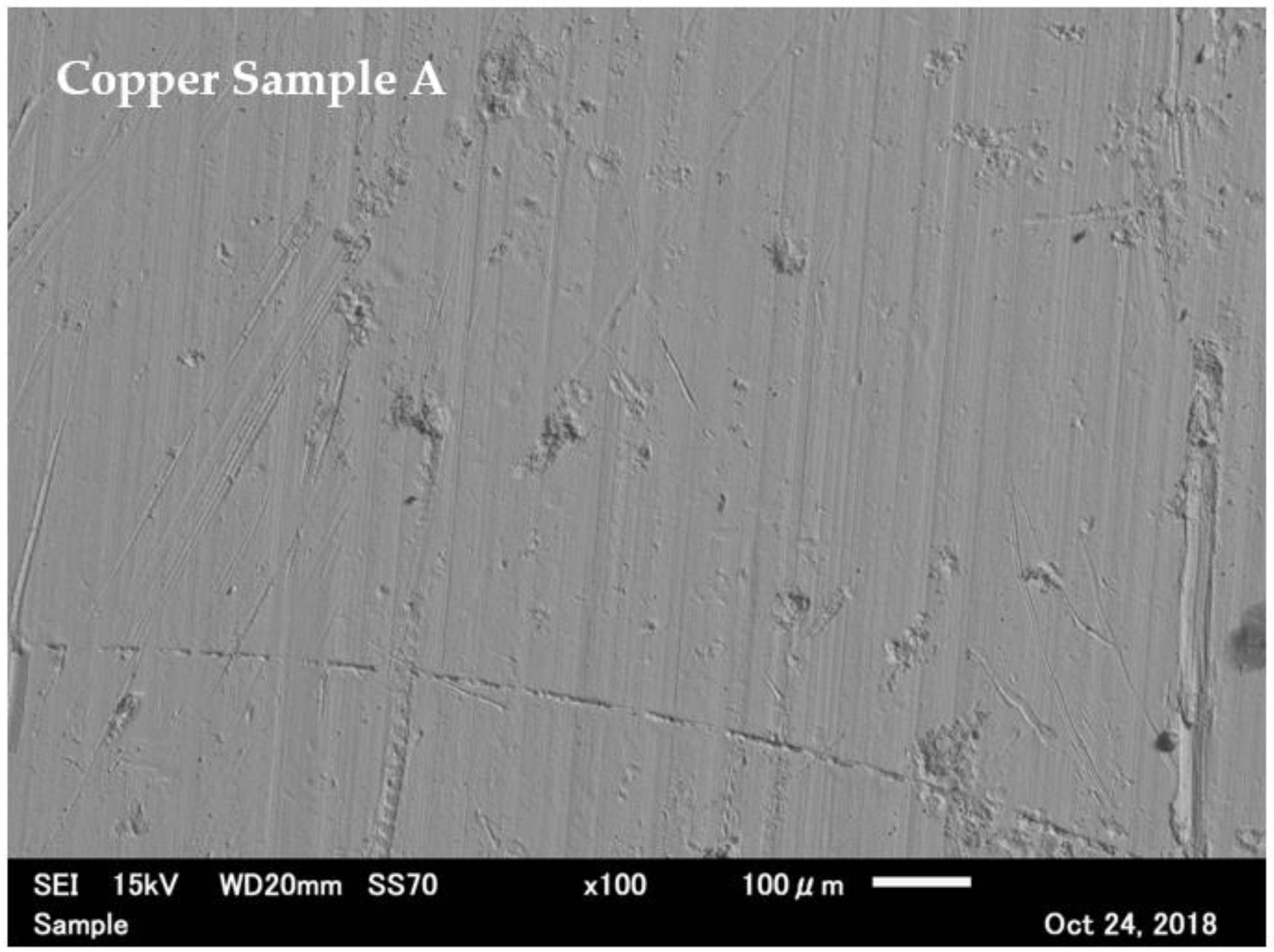
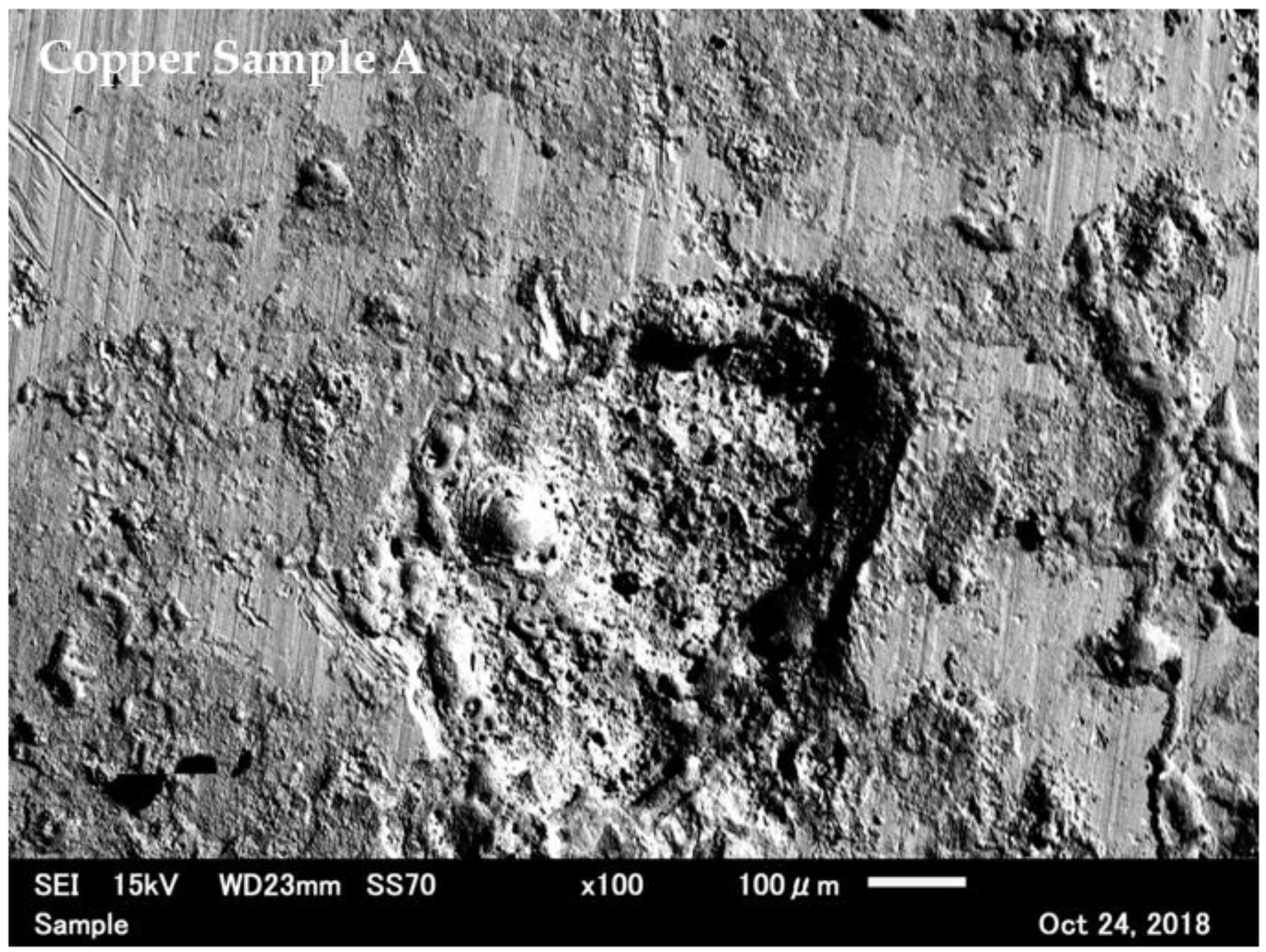
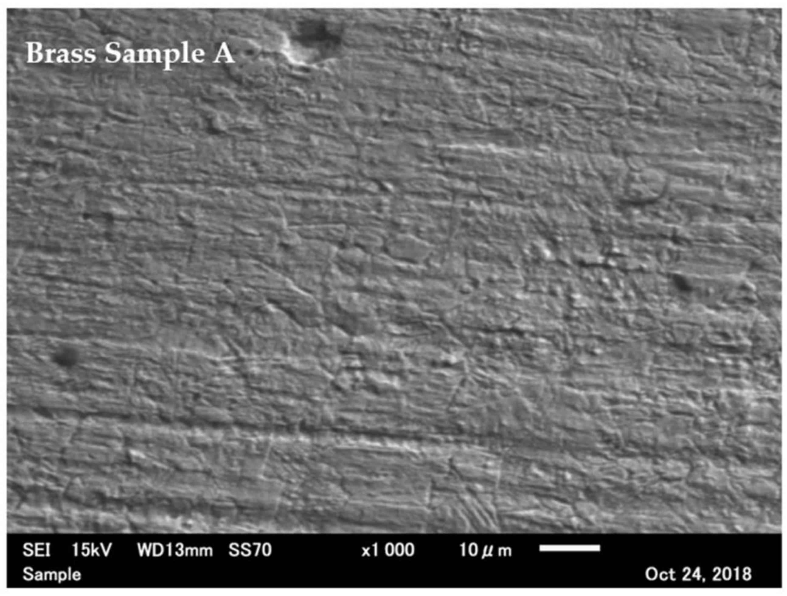
6.1. Contact Surface Inspection

The copper and brass contacts that were used in the experiment were examined using electron scanning microscopy (SEM, 6010LV, JEOL Ltd., Tokyo, Japan) and light microscopy (Measurescope UM2, Nikon Co., Ltd., Melville, NY, USA) to investigate the damage from the initial arcing contact. All of the copper samples used in the SEM were treated with a high concentration of hydrochloric acid (HCl) to remove any copper oxides from the surface. The acid was able to remove both types of oxides, copper(I) oxide (Cu2O) and copper(II) oxide (CuO), from the surface and to expose the damaged copper beneath. Hydrochloric acid does not react with pure copper. On the other hand, the brass contact surface was not treated with acid since brass can react with hydrochloric acid and form a zinc chloride solution that can damage and alter the brass surface. Figure 8 shows a comparison between a new copper surface and one damaged by the initial arc. The damage from a small initial arc is sufficient to reduce the effective contact area of the conductor. Figure 9 shows a comparison between a new brass contact surface and one damaged by the same electrical discharge setting as the copper sample. The brass sample exhibits less contact deterioration from the initial arc, although the damage is still largely visible and features a large patch of black residue. It is thought that a single small arc can inflict enough damage to reduce the overall current carrying capacity of the contact area, as is shown in Figure 10. However, in actual practice, it is not possible to determine the area of the contact surface that carries the current due to its microscopic scale. Any small movement by a human operator, either accidentally or from purposefully readjusting the setup, can drastically change the point of contact, thus altering the results. When the contact surface is subjected to repeat arcing, the average contact area may wear down leading to a reduction in the current carrying capacity and causing an over-current state.
Figure 11 and Figure 12 show a comparison between a new copper contact surface and a surface that has been damaged by a single contact electrical discharge of 4 A. Oxide formations were not observed on the surrounding copper material. The copper was leeched by the oxide at the contact surface and subjected to the electrical discharge. By taking the space of the affected area and effectively digging out the copper, the affected surface was replaced with its oxide counterpart. This type of erosion [21] is predominant when the electrical arc is energetic enough to remove a portion of the contact surface from the base material. Brass contact surfaces are much more resistant to electrical discharge wear, as is shown in Figure 13 and Figure 14. The result has the same pattern as what was observed by Noboru [22] and Song [23].

6.2. Formation of Copper Oxides

In the experiment, a copper-to-copper contact surface was primarily used. Copper has the property of being able to oxidize with oxygen at high temperatures. The main mechanism for initiating a glowing connection is as follows.
If the copper oxide bridge has already been established at the contact point and the bridge itself has been fully insulated, then an external heat source must be applied onto the contact area. In the normal usage of electrical appliances, the plug blade is in contact with the electrical socket, producing an electrical discharge. This type of discharge occurs when the electrical device has been switched on. Then, the contact point of the plug causes a current to flow into the appliance and initiate a spark. The electrical discharge near the oxide area is usually energetic enough to raise the temperature of the contact area to the point where copper is able to oxidize with oxygen in the air and turn into copper oxide. Common oxides formed from copper-based contacts are copper(I) oxide, Cu2O, and CuO. Both of these oxides exhibit electrical insulating properties at room temperature. Cu2O is considered to be a semiconductor material for temperatures between 200 °C and 500 °C [24,25,26]. As the temperature rises, the resistance decreases. The conductivity of the material also depends on the purity of the oxides themselves and whether there are enough electron holes to conduct effectively at certain temperatures. Additionally, according to the research mentioned earlier, copper oxide exhibits conductive properties at temperatures up to 1035 °C. CuO is also regarded as a semiconductor material. To make CuO conduct current, it must be doped to activate its carrier. In our experiments, both types of oxide material were produced in their natural states. Therefore, CuO is treated as an insulator in this research. To create CuO, Cu2O is first made by oxidizing 4Cu + O2. CuO is then produced by oxidizing 2Cu + O2 at temperatures between 300 °C and 800 °C. Cu2O does not require high temperatures at the copper contact surface to form. Regular uncoated copper surfaces will naturally form into Cu2O. At temperatures higher than 600 °C, CuO can react with certain gasses in the atmosphere, such as hydrogen, carbon monoxide, and carbon, creating a reduction reaction and converting CuO back into Cu. However, at these temperatures, Cu that was reduced from CuO can once again be oxidized back into Cu2O and CuO. This process continues in a cycle until the temperature is no longer high enough to continue the oxidizing process.

6.3. Mechanism behind Glowing Connections and Arc Faults

From the results of our experiments, we were able to deduce the mechanism behind series arc faults for copper-based contacts. The flow chart for the mechanism is shown in Figure 15.
A fire hazard from a glowing connection can be accelerated by an arc fault, as is explained in the steps below.
  • An initial electrical discharge produces small patches of insulating oxides.
  • A repeated discharge in the same location, such as what is caused when a plug is repeatedly removed from and reinserted into a socket during normal use, increases the area of the oxide patches.
  • Once the insulating patches, or the bulge, on the surface have increased to the point where the contact area is exhibiting overcurrent, the process will begin to produce heat through the Joule heating effect. At this stage, the process can be classified based on two main hazards. The first hazard occurs when there is no movement (insertion and reinsertion) of the plug. In this case, residual heat accumulates to the point where oxides can be created from the dissipation heat alone. The second hazard occurs when the contact surface moves so that it is no longer firmly connected, resulting in a vibration being created from the poor contact surface. This can induce a continuous electrical discharge that then greatly increases the temperature of the affected area, to the point where copper is able to oxidize with the atmosphere. Even if the contact area has already formed an oxide bridge, current can still pass through normally. This current flow, however, is not efficient. A small perturbation near the contact point by the operator or the environment can create a small initial spark that could then increase the temperature of the oxide patch near the affected area. If the spark is energetic enough, it can increase the temperature of the patch to the point where the oxide behaves as a semiconductor. A glowing connection or arc fault may then be initiated.
  • In a lower-current setting, a glowing connection can continue so long as there is current being provided and the resistance from the oxide bridge is not high enough to block the current flow. In a high-current setting, a glowing connection can be extremely energetic, so much so that it could melt off part of the oxide bridge. This could potentially split the bridge into two parts. In this case, the current flow stops. On the other hand, in the case where the oxide bridge grows to such a size where it cannot easily melt and break the contact, it will continuously leech copper from both contact surfaces and grow further still. Eventually, a certain size is reached such that the arc fault stops completely, and the glowing connection takes full effect.
  • Once the glowing contact area has been de-energized, the oxide bridge cools down to the point where the copper oxide behaves as an insulator. In this case, the contact surface does not pass any current. If the contact area has a small oxide bridge or a patch of conducting surface, then the contact area with the oxide bridge is able to pass current. The temperature of the small patch of conductive surface may increase due to overcurrent. If the temperature rises to the point where the majority of the oxide bridge changes its state back into a semiconducting phase, then the glowing connection will revert back to the state in step 3. The cycle will continue until the oxide bridge is broken or it is too large to pass current when the circuit is de-energized.

7. Conclusions

We were able to conclude from our study that an arc fault in a copper-based contact is not of the classical spark gap theory where an electrical breakdown happens between a very small gap with a certain atmosphere. The mechanism behind a copper-based low voltage arc fault is largely another state of glowing connection where the semiconducting property of the material creates an illusion of a sparking gap on the affected area. Our study pointed out that common commercial electrical contact surfaces, especially replacement electrical plugs used around the world, are generally made from non-plated copper or electrical grade brass. When the contact surface is subjected to incorrect handling, such as turning on the electrical appliance before turning on the socket, a small electrical discharge will be created that is sufficient to reduce the contact surface area. Repeatedly mishandling the socket can drastically increase the chance of subjecting the contact point to the Joule heating effect. The risk becomes more pronounced when the contact surface is already being used at its maximum current rating. Due to the semiconducting property of copper oxides, once the temperature from the Joule heating effect is high enough to reduce the resistance of the oxides at the contact area. The specific voltage and current waveform pattern of an arc fault exclusive to copper oxides may occur and furthermore increase the temperature, in turn drastically increasing the risk of an electrical fire. The mechanism for this type of arc fault is unique to contact surfaces that are made from copper or copper alloys. Hence, the other type of material’s arc fault, such as steel-based contact, cannot be used as a comparison to all types of low-voltage arc fault. It is also concluded that copper-based arc-fault risk is not exclusive to electrical plugs, sockets, and cables. Any electrical device that is made from internal moving contact parts made of copper is a fire hazard risk. At this time, with the proliferation of small electrical devices around household, this type of electrical fire around the world may increase significantly in the upcoming future. Further research may be required to study the electrical behavior of the iron oxides and create the comparison between the other main types of conductors used in households. In conclusion, any conducting surface used in the contact part that is made of copper or alloys of copper bear an inherent risk of electrical fire hazard due to its properties. In the future, if we want to reduce the risk of such an incidence from this type of hazard, all types of contact conductor should be made from non-copper materials, or all the surfaces must be plated with corrosive resistance material. As, currently, nickel-plated copper is mainly used only on the plug blade but not the interior of the electrical socket, silver-plating is used in electrical switches and breakers which may prove to be insufficient in reducing the risk. The explained mechanism can also be used to pinpoint and create the mean to detect the phenomenon more accurately.

Author Contributions

Conceptualization, S.W.; methodology, S.W.; validation, S.W. and K.Y.; formal analysis, S.W.; investigation, S.W.; resources, K.Y.; data curation, S.W.; writing—original draft preparation, S.W.; writing—review and editing, K.Y.; visualization, S.W.; supervision, K.Y.; project administration, K.Y.; funding acquisition, K.Y. All authors have read and agreed to the published version of the manuscript.

Funding

The study was supported by Tokyo Fire Department.

Institutional Review Board Statement

Not applicable.

Informed Consent Statement

Not applicable.

Data Availability Statement

Not applicable.

Conflicts of Interest

The authors declare no conflict of interest.

References

  1. Tokyo Fire Department: Cases of Fire Incidents. Available online: https://www.tfd.metro.tokyo.lg.jp/hp-cyousaka/kasaijittai/r02/data/R2_AllKasaiWeb.pdf (accessed on 12 January 2021). (In Japanese).
  2. Tokyo Fire Department: Condition of Fire Incidents. Available online: https://www.tfd.metro.tokyo.lg.jp/saigai/toukei/r02/d1/gaiyo.pdf (accessed on 12 January 2021). (In Japanese).
  3. Martel, J.M. Series Arc Faults in Low-Voltage AC Electrical Installations. Ph.D. Thesis, Technische Universitat Ilmenau, Ilmenau, Germany, 2018. [Google Scholar]
  4. Meese, W.J.; Beausoliel, R.W. Exploratory Study of Glowing Electrical Connections; NBS BUILDING SCIENCE SERIES 103; National Bureau of Standards U.S. Department of Commerce: Washington, DC, USA, 1977. [Google Scholar]
  5. Hagimoto, Y.; Kinoshita, K.; Hagiwara, T. Phenomenon of glow at the electrical contacts of copper wires. Natl. Res. Inst. Police Sci. Rep. 1988, 41, 30–37. [Google Scholar]
  6. Hagimoto, Y.; Kinoshita, K.; Hagiwara, T. Glowing Phenomenon at the Contact of Different Kind of Metals. Summary of Annual Meeting of Japan Society for Safety Engineering. Available online: http://www.tcforensic.com.au/docs/japan/japanall.pdf (accessed on 12 January 2021).
  7. Shea, J.J. Glowing Contact Physics. In Proceedings of the 52nd IEEE Holm Conference on Electrical Contacts, Montreal, QC, Canada, 25–27 September 2006. [Google Scholar]
  8. Urbas, J. Glowing Connection Experiments with Alternating Currents Below 1 Arms. IEEE Trans. Compon. Packag. Manuf. Technol. 2010, 33, 777–783. [Google Scholar] [CrossRef]
  9. Slade, P.G. Electrical Contacts: Principles and Applications, 2nd ed.; CRC Press, Taylor & Francis Group LLC.: Boca Raton, FL, USA, 2014; pp. 79–83. [Google Scholar]
  10. Caven, R.W.; Jalali, J. Predicting the contact resistance distribution of electrical contacts by modeling the contact interface. In Proceedings of the 37th IEEE HOLM Conference on Electrical Contacts, Chicago, IL, USA, 6–9 October 1991. [Google Scholar]
  11. Timsit, R.S. Electrical conduction through small contact spots. In Proceedings of the 50th IEEE Holm Conference on Electrical Contacts and the 22nd International Conference on Electrical Contacts Electrical Contacts, Seattle, WA, USA, 23 September 2004. [Google Scholar]
  12. Sritriai, E.; Kittiratsatcha, S.; Polmai, S. Low Voltage Series Arc Fault Detection Using Rogowski Coil. In Proceedings of the International Conference on Engineering, Applied Sciences and Technology, Phuket, Thailand, 4–7 July 2018. [Google Scholar]
  13. Li, S.; Yan, Y. Fault Arc Detection Based on Time and Frequency Domain Analysis and Radom Forest. In Proceedings of the International Conference on Computer Network, Electronic and Automation, Xi’an, China, 24–26 September 2021; pp. 248–252. [Google Scholar]
  14. Ming, Z.; Tian, Y.; Zhang, F. Design of arc fault detection system based on CAN bus. In Proceedings of the International Conference on Applied Superconductivity and Electromagnetic Devices, Chengdu, China, 25–27 September 2009; pp. 308–311. [Google Scholar]
  15. Shea, J.J. Glowing connections in DC circuits. In Proceedings of the IEEE Holm Conference on Electrical Contacts, Denver, CO, USA, 10–13 September 2017; pp. 264–274. [Google Scholar]
  16. Shea, J.J.; Zhou, X. Material Effect on Glowing Contact Properties. IEEE Trans. Compon. Packag. Technol. 2009, 32, 90–97. [Google Scholar] [CrossRef]
  17. Ettling, B.V. Glowing Connections. Fire Technol. 1982, 18, 344–349. [Google Scholar] [CrossRef]
  18. Sletbak, I.; Kristensen, R.; Sundklakk, H.; Navik, G.; Runde, M. Glowing contact areas in loose copper wire connections. In Proceedings of the 37th IEEE HOLM Conference on Electrical Contacts, Chicago, IL, USA, 6–9 October 1991. [Google Scholar]
  19. Iliuţă, C. Experimental research on electrical resistance of microcontacts. DOCT-US 2011, 3, 30. [Google Scholar]
  20. Abbaoui, M.; Lefort, A.; Sallais, D.; Jemaa, N.B. Theoretical and experimental determination of erosion rate due to arcing in electrical contacts. In Proceedings of the 52nd IEEE Holm Conference on Electrical Contacts, Montreal, QC, Canada, 25–27 September 2006. [Google Scholar]
  21. Mcbride, J.W. The volumetric erosion of electrical contacts. IEEE Trans. Compon. Packag. Technol. 2000, 23, 211–221. [Google Scholar] [CrossRef] [Green Version]
  22. Wakatsuki, N.; Watanabe, T. Electric Characteristics and Contact Area Features of Melting when Making and Breaking Contacts. In Proceedings of the IEEE 61st Holm Conference, San Diego, CA, USA, 11–14 October 2015. [Google Scholar]
  23. Song, J.; Koch, C. Wear Patterns and Lifetime of Electric Contacts. In Proceedings of the 54th IEEE Holm Conference on Electrical Contacts, Orlando, FL, USA, 27–29 October 2008. [Google Scholar]
  24. Anderson, J.S.; Greenwood, N.N. The Semiconducting Properties of Cuprous Oxide. Proc. R. Soc. Lond. Ser. A Math. Phys. Sci. 1952, 215, 353–370. [Google Scholar]
  25. Ogwu, A.A.; Darmal, T.H.; Bouquerel, E. Electrical resistivity of copper oxide thin films prepared by reactive magnetron sputtering. J. Achiev. Mater. Manuf. Eng. 2007, 24, 172–177. [Google Scholar]
  26. Rahnama, A.; Gharagozlou, M. Preparation and properties of semiconductor CuO nanoparticles via a simple precipitation method at different reaction temperatures. Opt. Quant. Electron. 2012, 44, 313–322. [Google Scholar] [CrossRef]
Figure 1. Equivalent circuit diagram of the experiment setup. Note that the setup does not have capacitors for power factor correction connected to the isolating transformer. The setup near the contact area is shown in the embedded picture. Probe A is the neutral line and Probe B is the hotline.
Applsci 12 04710 g001
Figure 2. Pictures of the experimental apparatuses. (a) The copper oxide powder used to accelerate the growth of the oxide bridge. (b) A brass electrical plug that is typical of what is used in Japan for DIY repair and replacements. (c) A typical electrical socket used in Japan. The objects at the bottom of the image are the interior copper contacts from the socket. (d) The clamping apparatus used to move the plug and blade and to hold them firmly while data was recorded.
Applsci 12 04710 g002
Figure 3. Pictures of a typical arc-fault state. (a) The arcing state between the copper and brass contacts when it is at its lowest energetic state near the zero-crossing point of the current. (b) The arcing state 10 ms later when the arc is at its most energetic state and is much more prominent.
Applsci 12 04710 g003
Figure 4. The voltage and current waveforms in the arcing state. The red circles show the voltage drops at every zero-crossing point of the current. The green circles show where the current shoulder occurs. (a) A significant voltage drop and a longer current shoulder for a 100 W load. The greater power draw by the load results in a smaller current difference and drop between the hot and neutral lines. (b) The current shoulder and voltage drop for a 400 W load. (c) The current shoulder and voltage drop for an 833 W load.
Applsci 12 04710 g004
Figure 5. Thermal images of the system state with and without an arc fault. The arc fault was maintained for 2 min. The temperature around the contact point did not reach 700 °C. (a) 4 A, 2-min arcing. (b) 4 A, initial state.
Applsci 12 04710 g005
Figure 6. The voltage waveform and the vibration velocity waveform. (a) When there is poor contact in an arc-fault state, it is observed that the point of contact generates vibration pulses at twice the frequency of the AC power supply. (b) When contact between the two electrodes is poor with no electrical discharge between the contact points, the vibration is still present, albeit at a significantly lower strength than that in the electrical discharge state.
Applsci 12 04710 g006
Figure 7. FFT results for the vibration velocity waveform. (a) FFT result for an arc fault present at 8.33 A. (b) FFT result for the normal state when both contacts are held firmly together. Notice that only the 50 Hz component is left, which may be caused by nearby vibrations from the power supply when there is no arc-fault state.
Applsci 12 04710 g007
Figure 8. The copper contact surface. (a) The new copper contact surface under a microscope. (b) The same copper contact surface after being subjected to an electrical arc from normal contact. The current that passed through the contact was 4 A. Note that the copper surface loses its mass after the contact arc.
Applsci 12 04710 g008
Figure 9. The brass contact surface. (a) The new brass contact surface under a microscope. (b) The same brass contact surface after being subjected to an electrical arc from normal contact. The current that passed through the contact was 4 A. Note that brass surface leech others copper contact and form bulges of oxides on the surface.
Applsci 12 04710 g009
Figure 10. A new copper contact surface after being subjected to an electrical arc when 8.33 A of current passed through the contact. Notice that the black residue is much more apparent here than in the lower-current setup. Magnification at 20×.
Applsci 12 04710 g010
Figure 11. A new copper contact surface before it was subjected to an electrical arc, viewed under an electron microscope at 100× magnification.
Applsci 12 04710 g011
Figure 12. The same copper contact surface after it was subjected to an electrical arc of 4 A. The sample was treated with HCl to remove oxides on the surface. The sample is viewed under an electron microscope at 100× magnification.
Applsci 12 04710 g012
Figure 13. A new brass contact surface before it was subjected to an electrical arc, viewed under an electron microscope at 1000× magnification.
Applsci 12 04710 g013
Figure 14. The same brass contact surface after it was subjected to an electrical arc of 4 A, viewed under an electron microscope at 100× magnification. This brass sample was not treated with HCl due to zinc being reactive to the acid which may damage the surface.
Applsci 12 04710 g014
Figure 15. The process that leads to electrical fires from accumulated heat and arc-fault states.
Applsci 12 04710 g015
Table 1. Resistance and temperature in a copper-to-copper glowing discharge.
Experiment No. (Cu-Cu Discharge)Temperature Range in Degrees CelsiusResistance Values in Ohms
Sample 121 °C–122 °C–238 °C–520 °C∞–124 kΩ–16 kΩ–530 Ω
Sample 221 °C–131 °C–226 °C–520 °C∞–135 kΩ–26 kΩ–744 Ω
Sample 321 °C–135 °C–231 °C–520 °C∞–150 kΩ–16 kΩ–631 Ω
Sample 421 °C–146 °C–230 °C–520 °C∞–141 kΩ–19 kΩ–253 Ω
Sample 521 °C–126 °C–217 °C–520 °C∞–133 kΩ–24 kΩ–342 Ω
Sample 621 °C–119 °C–257 °C–520 °C∞–129 kΩ–29 kΩ–122 Ω
Publisher’s Note: MDPI stays neutral with regard to jurisdictional claims in published maps and institutional affiliations.

