Article

A Description Logic Based Ontology for Knowledge Representation in Process Planning for Laser Powder Bed Fusion

1
Guangxi Key Laboratory of Manufacturing System and Advanced Manufacturing Technology, School of Mechanical and Electrical Engineering, Guilin University of Electronic Technology, Guilin 541004, China
2
Guangxi Key Laboratory of Intelligent Processing of Computer Images and Graphic, School of Computer Science and Information Security, Guilin University of Electronic Technology, Guilin 541004, China
*
Author to whom correspondence should be addressed.
Appl. Sci. 2022, 12(9), 4612; https://doi.org/10.3390/app12094612
Submission received: 31 March 2022 / Revised: 27 April 2022 / Accepted: 28 April 2022 / Published: 4 May 2022

Abstract

:
Laser powder bed fusion (LPBF) provides a rapid and cost-effective solution for fabricating metallic parts with near full density and high precision, strength, and stiffness directly from metallic powders. In LPBF, process variables are widely recognised as fundamental factors that have important effect on the quality of the built parts. However, activity of designing process variables for LPBF, i.e., process planning for LPBF, still heavily depends on knowledge from domain experts. This necessitates a knowledge base that enables the capture, representation, inference, and reuse of existing knowledge. In this paper, a description logic (DL) based ontology for knowledge representation in process planning for LPBF is presented. Firstly, a set of top-level DL entities and specific DL entities and semantic web rule language (SWRL) rules for part orientation, support generation, model slicing, and path planning are created to construct the ontology. The application of the ontology is then illustrated via process planning on an LPBF part. Finally, the benefits of the ontology are demonstrated through a few examples. The demonstration results show that the ontology has rigorous computer-interpretable semantics, which provides a semantic enrichment model for LPBF process planning knowledge and enables automatic consistency checking of the ontology, knowledge reasoning on the ontology, and semantic query from the ontology. This would lay solid foundation for development of a process planning tool with autonomous decision-making capability.

1. Introduction

Laser powder bed fusion (LPBF) is an additive manufacturing (AM) process that uses a laser beam to selectively melt metallic powders together to additively manufacture metal parts [
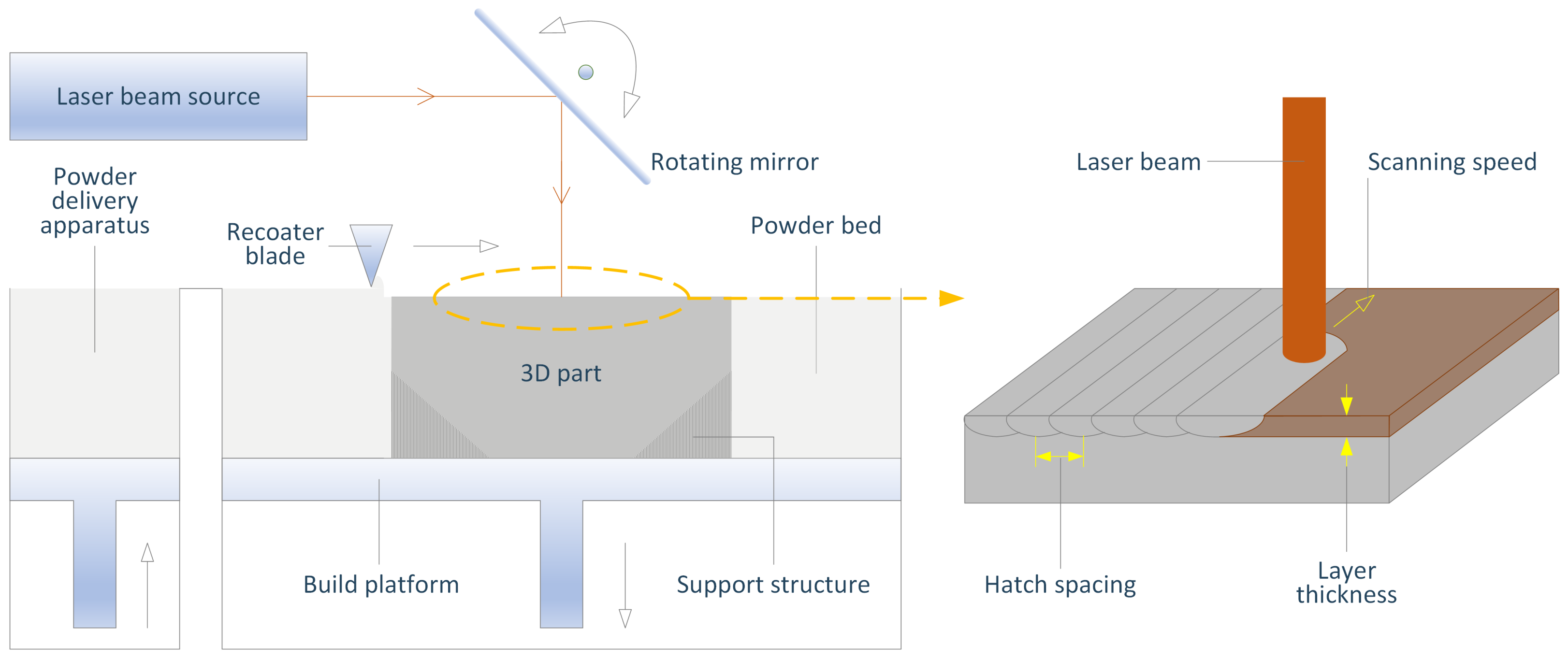
1]. The schematic of this process is depicted in Figure 1. An LPBF machine mainly includes a powder bed, a powder delivery apparatus, a build platform, a recoater blade, a rotating mirror, and a laser beam source. The process of using an LPBF machine to fabricate a three-dimensional (3D) part generally consists of the following steps:
  • A layer of powder material with specified thickness is spread over the build platform from the powder delivery apparatus by the recoater blade;
  • A moving laser beam with certain power selectively scans the layer of powder material with certain speed to create a layer of the 3D part;
  • The build platform steps down by one layer thickness and a new layer of powder material is distributed evenly across the build platform;
  • The second and third steps are repeated until the 3D part is fully built.
LPBF has advantages in providing high flexibility for geometric design and achieving geometric complexity without additional cost, which are the common advantages of AM technologies over traditional manufacturing technologies. More importantly, LPBF enables rapid fabrication of different metallic parts in a mixed batch with near full density and high precision, strength, and stiffness directly from metallic powders at no extra cost [2]. This feature makes it an attractive technology for producing functional components in a number of key industrial sectors, such as the aerospace, automotive, and biomedical sectors [3].
Figure 1. Schematic diagram of the LPBF process.
Applsci 12 04612 g001
In general, the process of using LPBF to realise a part meeting certain quality requirements includes a set of activities, where process planning is an important one. In conventional manufacturing, process planning is an activity of determining appropriate sequence of operations and process variables for converting a workpiece from an engineering drawing to its final form. In LPBF, the engineering drawing is replaced by a 3D model. The aim of process planning remains the same, namely to determine appropriate sequence of LPBF operations or process variables to enable efficient and accurate build of an LPBF part from its 3D model. In process planning for LPBF, the process variables to be designed include build orientation, support structure, slices, laser scanning path, and process parameters. These variables are widely recognised as fundamental factors that have important influence on the quality of the built part [4,5,6,7,8]. However, process planning for LPBF is still considered as a challenging activity [9,10] because of the following reasons. Firstly, the physical and chemical processes of LPBF are complex. The lack of a complete understanding of these underlying processes brings great difficulty to the development of optimal process planning methods to build high-quality components [2]. Secondly, most of the existing process planning methods for LPBF focus on specific variables, materials, or structures rather than general strategies. They are difficult to be transferred directly to a build with new variables, materials, or structures. Thirdly, most of the current process planning tools for LPBF are configured by users manually without a standard procedure. There is not yet a tool with autonomous decision-making capability [4,5,6,7,8]. These limitations necessitate a process planning knowledge base that enables the capture, representation, inference, and reuse of existing knowledge about the LPBF process.
In this paper, a description logic (DL) based ontology for knowledge representation in process planning for LPBF is constructed. DLs, a family of formal knowledge representation languages, are well-known for providing rigorous logic-based semantics to support knowledge reasoning [11]. Ontology, a shared, explicit, and formalised specification of concepts, relations, instances, and axioms in an application domain, provides effective means to capture, represent, and reuse domain knowledge [12]. A DL-based ontology is an ontology using a DL as representation language. The most prominent feature of DL-based ontologies is that they can achieve semantic representation and exchange and knowledge discovery and reuse. Although application of DL-based ontologies is rooted in the field of semantic web, it has been extended to many other fields during the past three decades. In the field of advanced manufacturing, DL-based ontologies have been used to improve the interoperability of industrial information systems [13], achieve knowledge reuse and discovery in product lifecycle management [14], exchange computer-aided design model data [15], and implement intelligent design of tolerance specifications [16]. Through a DL-based ontology, the knowledge in process planning for LPBF can be formalised in DL and semantic web rule language (SWRL) [17] and represented and stored in web ontology language (OWL) [18]. As three benefits of the constructed DL-based ontology, consistency checking, knowledge reasoning, and semantic query can be performed via DL, DL and SWRL, and DL, sparql protocol and rdf query language (SPARQL) [19], and semantic query-enhanced web rule language (SQWRL) [20], respectively.
The remainder of the paper is organised as follows: an overview of related work is provided in Section 2. The details of the constructed DL-based ontology are explained in Section 3. Section 4 documents an application of the ontology and illustrations of the benefits of the ontology. Section 5 ends the paper with a conclusion.

2. Related Work

An ideal model for AM knowledge representation is preferably a standardised model for practical applications [21]. During the past few decades, many standardised models for data representation in AM have been developed [22], but there has not yet been a standardised model for knowledge representation in AM. To fill this gap, many models have been presented within academia, which can be divided into the following categories based on the knowledge representation methods used in them:
  • Graph model [23]: this model was presented to formulate the design guidelines for AM. In the model, a set of design guidelines for AM are first defined in a graph form based on relevant literature. Then, the 3D model of a component is decomposed into a group of constitutive features. These features and the relationships between them are identified and represented using graphs. After that, the defined design guidelines are leveraged to revise the offending features to alleviate the manufacturability issue. Finally, the best design for component build is obtained via repeating the first three steps iteratively. The approach can be used by those designers who find it difficult to integrate all the constraints into a unified AM design process. However, it improves the AM design only on the basis of manufacturability. Mechanical strength is not considered in the improvement.
  • Finite state automata model [24]: this model was constructed to represent AM design knowledge to support personalised AM. In the model, a formal design process structure combining design for personalisation and design for AM is first established. Then, the artifact-user interactions are formally represented using a finite state automata based on the established structure. Through applying the affordance, effectivity, and preference properties, the artifact properties related to behaviours and preferences of users are systemically linked to design requirements of AM artifacts. The finite state automata model provides a set of formal representations that capture design requirements to improve personalisation level of AM while maintaining the freedom of AM design. However, it can only be applied to the stages of conceptual design and preliminary design and has not yet been included for consideration of process planning.
  • Network model [25]: this model was developed to simulate AM processes. In the model, the system of direct material deposition process is taken as an illustrative case study. Networks are first used to visualise the general view of the system functions and the causal relationships between system variables. Then, a set of causal graphs between governing dimensionless products are defined to simplify the causal graphs between system variables. Through the simplification, the causal relationships between system variables are directly extracted before carrying out experiments. The network model provides a feasible way to simulate the direct material deposition process. However, it still needs to be further extended when it is utilised to simulate other AM processes.
  • Function modelling language model [26]: this model was established to structurally represent the process-related data and knowledge in LPBF using a function modelling language and align them with specific sub-processes of powder bed fusion. It classifies an LPBF product realisation process into six activities, which are product modelling, product model tessellation, process planning, monitoring and control, post process, and quality inspection. On the basis of such classification, the activities process planning and monitoring and control and the data and knowledge associated with them are modelled. The function modelling language model provides a way to understand the organisation of LPBF product realisation process activities and sub-activities and the data flows among them. It also provides a common terminology and new process knowledge for LPBF data management. However, the model is just a conceptual model of the activities. The modelling of specific data and knowledge in each activity is not included.
  • Worksheet model [27]: this model was presented to simplify the guidelines of design for AM for novice and intermittent users. In the model, the existing guidelines of AM design are firstly summarised from a certain number of representative research articles. Based on the summarisation, a one-page visual worksheet of the guidelines of design for AM is developed. The effectiveness of the worksheet is demonstrated via several test experiments. The worksheet model can help designers evaluate the potential quality of a component manufactured by AM processes and indirectly recommend feasible methods to redesign it. Its direct benefit is to filter out bad designs before manufacturing, which reduces the time spent on manufacturing and redesign. However, the model is based on the samples provided by a single source, which could limit its potential performance.
  • Formal rule model [28]: this model was constructed to represent the design rules with modularity for AM. In the model, the fundamental relations among geometry, process, and material are first decomposed into reusable modules. Then, the modules are described using if-then rules. On the basis of the rules, parts are specialised to represent the process-related parameters for different AM processes. The formal rule model provides consistent and repeatable interpretations of an AM design guideline in different design and process conditions. It can also be used to explain the design principles that are independent of process to those users who are not familiar with AM technologies. Since the core of the model is to reconfigure the existing design rules, rather than to develop new rules, the basic AM principles can be preserved, and meanwhile the customisation and explicit representation of AM design rules can be implemented.
  • Bayesian network model [29]: this model was established to fill the knowledge gap between designers and AM technologies. It is hierarchically organised and consists of an overview layer and a detailed information layer. Different types of nodes and their causal relationships in each layer are characterised by Bayesian networks. A knowledge management system for supporting AM was then developed. This system can help designers understand the capabilities of AM processes and form appropriate design solutions at the design stage, which reduces the uncertainty of AM processes to some extent.
  • Category theory model [30]: this model was developed to formalise general knowledge in design and process control for powder bed fusion. In the model, a collection of guidelines and rules for these two activities are encapsulated and represented using categorical structures. The category theory model provides a framework to captured, accessed, and interrogated the structured knowledge. However, it has not yet included the representation of specific data in the two activities.
A summarisation of the models above at the aspects of published year, representation method, represented specific AM knowledge, and targeted AM process is provided in Table 1. In addition to these models, the use of ontologies in AM knowledge representation has been gained importance and popularity within academia during the past two decades. Many ontologies [31,32,33,34,35,36,37,38,39,40,41,42,43,44,45,46,47,48,49,50,51,52] have been presented in this period. A summarisation of these ontologies at the aspects of published year, representation languages, represented specific AM knowledge, and targeted AM process is provided in Table 2.
As can be seen from Table 1 and Table 2, each model/ontology has its specific usage in AM knowledge representation. Some models/ontologies are targeted at general AM processes, while each of other models/ontologies is constructed for one specific AM process, including direct material deposition, LPBF, powder bed fusion, lithography-based ceramic manufacturing, or wire arc additive manufacturing. It can also be seen from the two tables that the models and ontologies related to knowledge representation in process planning for LPBF include the function modelling language model [26], category theory model [30], and ontologies in [31,32,33,35,37,39,40,42,43,47,48,49]. However, research gap is evident due to the following reasons: both the function modelling language model [26] and category theory model [30] are conceptual models and do not involve the modelling of specific data and knowledge in process planning for LPBF; the ontologies in [31,32,33,35,37,39,40,42,43] are targeted at general AM processes and are difficult to be applied to process planning for LPBF directly (need further modifications and extensions); although the ontologies in [47,48,49] were all developed for the LPBF process, their main purpose is not to represent the knowledge at the process planning stage. To fill the research gap, a DL-based ontology dedicated to knowledge representation in process planning for LPBF is presented in this paper.

3. DL-Based Ontology

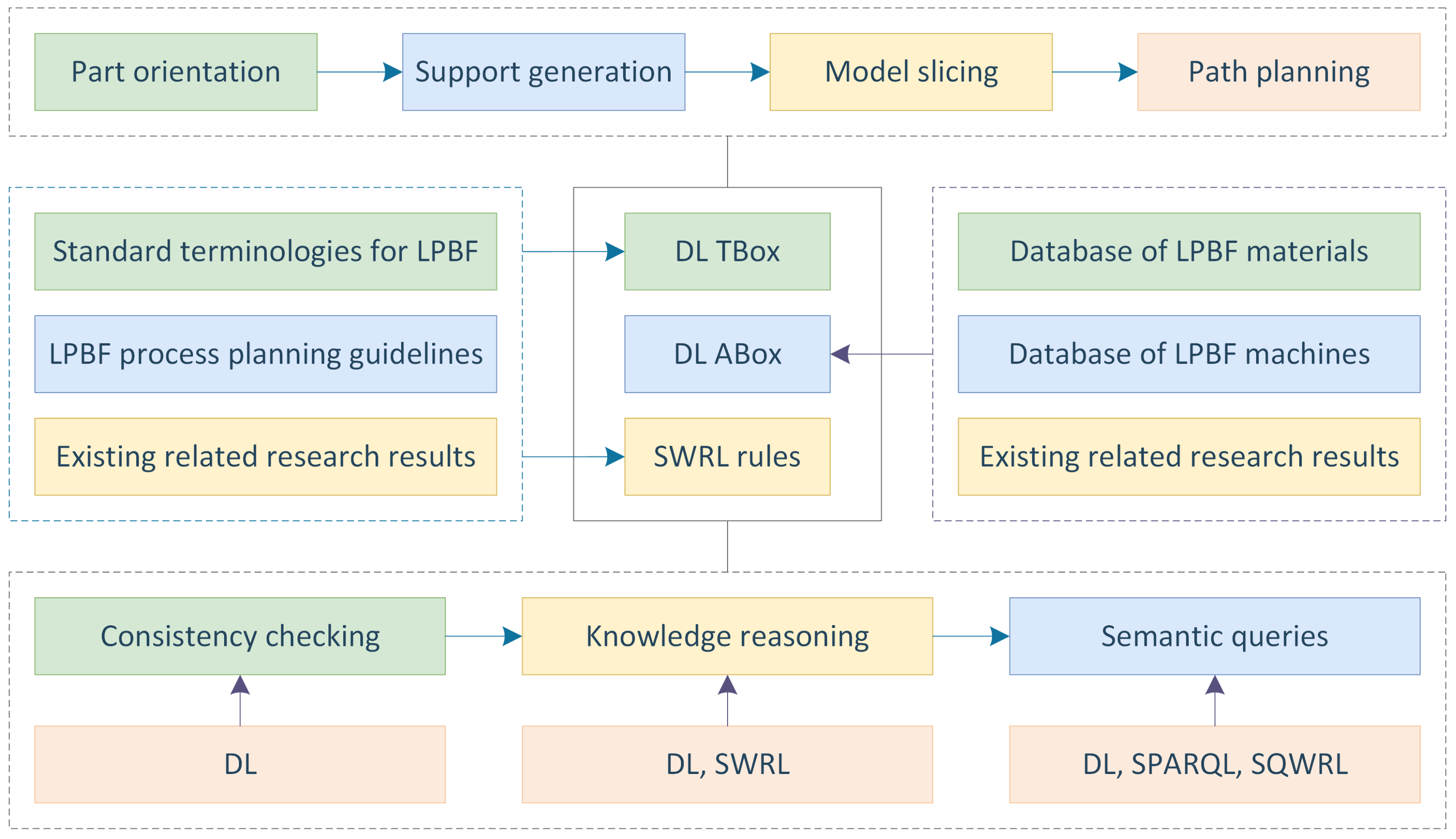
A DL-based ontology generally consists of a DL terminology box (TBox), a DL assertion box (ABox), and a set of SWRL rules. The DL TBox is a collection of concepts, relations, and definitions of concepts (terminological axioms). A set of concept assertions, relation assertions, and instance assertions (assertional axioms) constitute the DL ABox. The SWRL rules are used to describe the knowledge that cannot be described by DL. In this section, a DL-based ontology for representation of the LPBF process planning knowledge is developed using Protégé [53] according to standard terminologies for LPBF (ISO/ASTM 52900, 2021), LPBF process planning guidelines (ISO/ASTM 52911-1, 2019; ISO/ASTM 52911-2, 2019), database of LPBF materials [54], database of LPBF machines [54], and existing related research results [4,5,6,7,8]. The schematic diagram of this ontology is shown in 
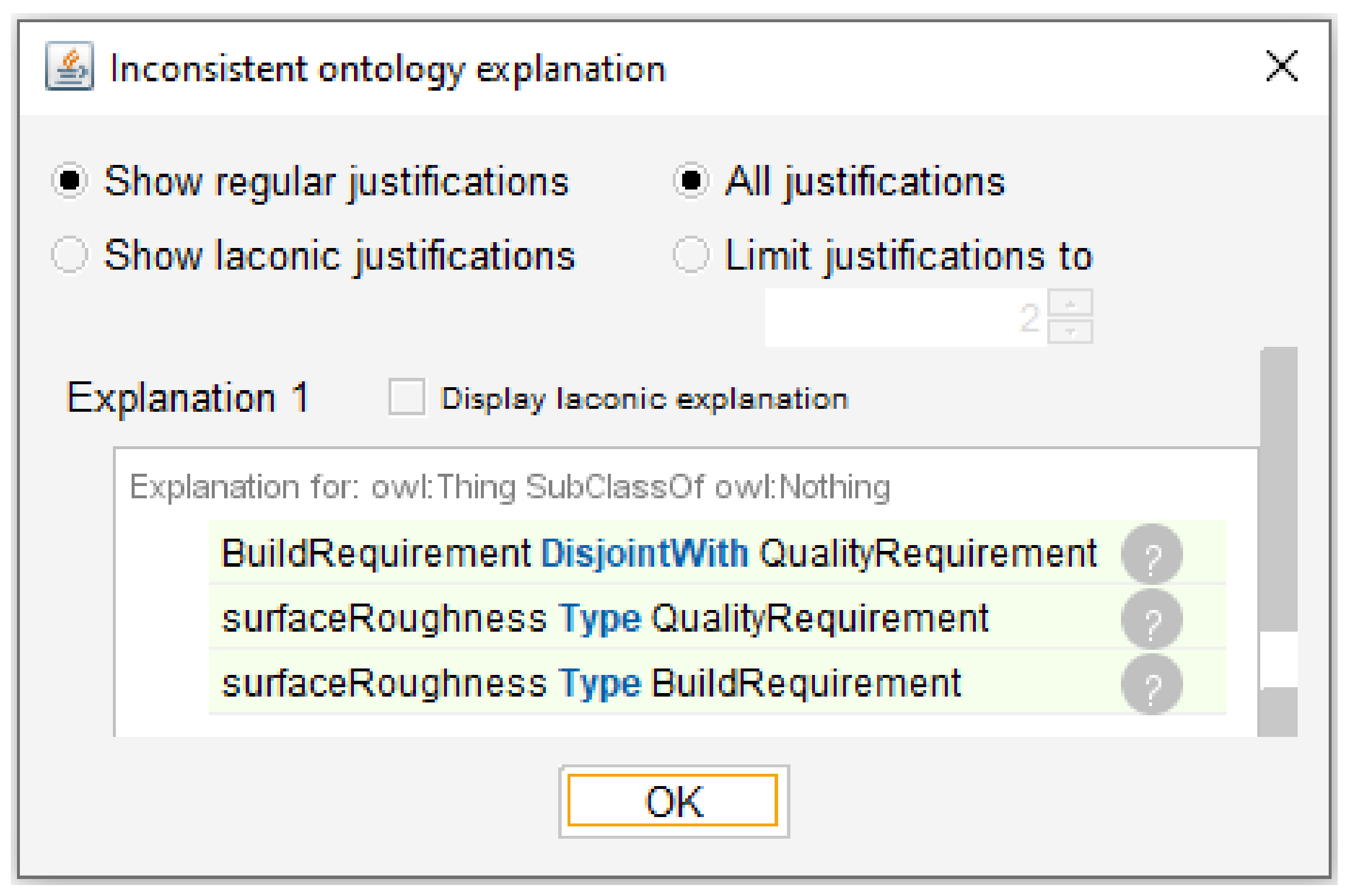
Figure 2. Benefiting from the advantages of the developed ontology, the semantics of LPBF process planning data are enriched greatly, and consistency checking, knowledge reasoning, and semantic query, which are not available in current process planning tools for LPBF, can be performed via DL, DL, and SWRL, and DL, SPARQL, and SQWRL, respectively.
In the following subsections, the details of the ontology will be described in a top-down manner. For the sake of clarity, the following labelling convention will be adopted: all entity names are in italics (e.g., LpbfMachine, isBasedOn, eosintM270); the first letters of all DL concept (OWL class) names are in capitalised case (e.g., Lpbf, ProcessPlanning); all DL relation (OWL property) names have a prefix of ‘has’ or ‘is’ (e.g., hasEnergySource, isApplicableFor); the first letters of all DL instance (OWL individual) names are in lower case (e.g., ti6Al4V, alSi10Mg).

3.1. Top-Level Entities

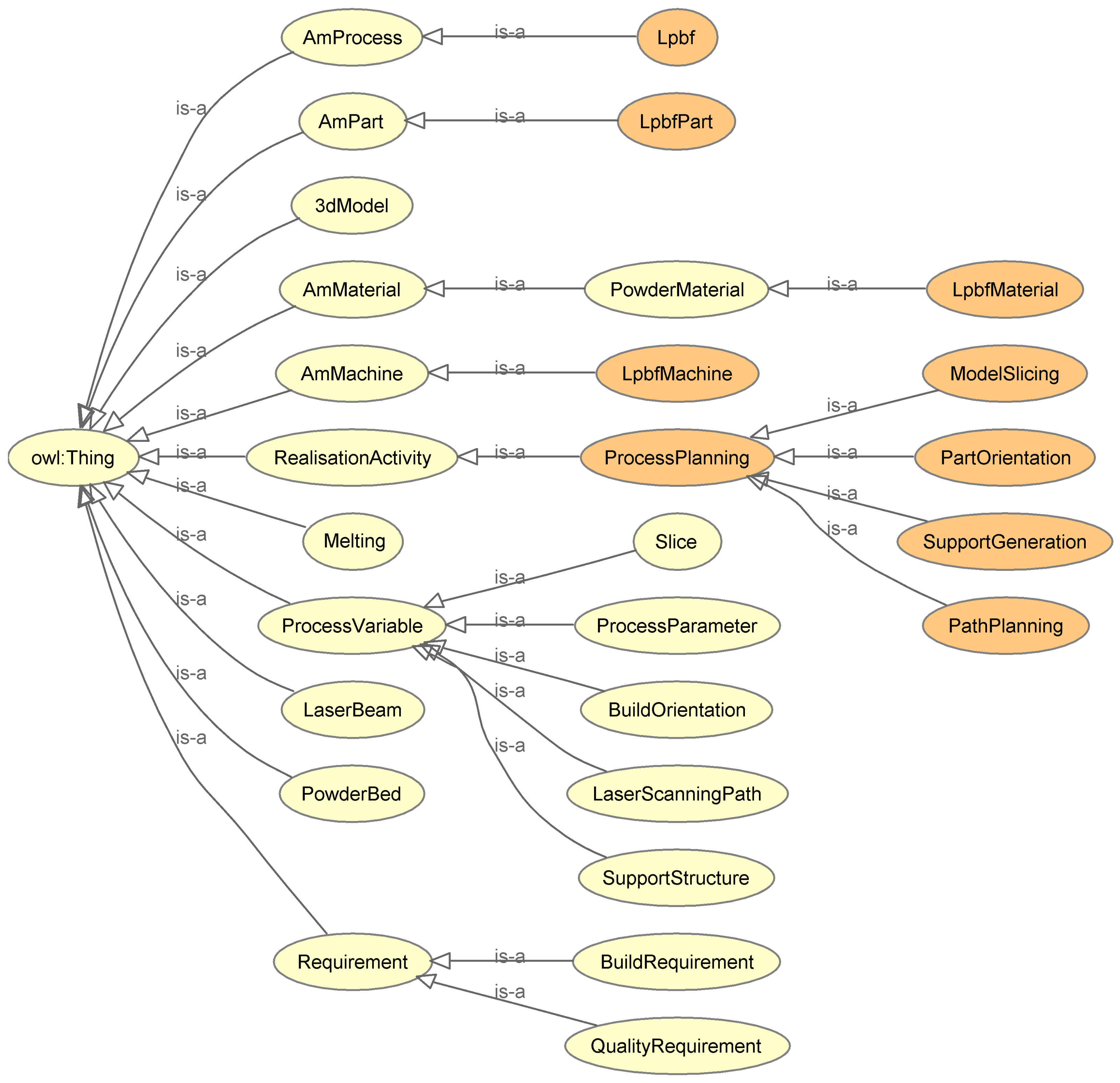
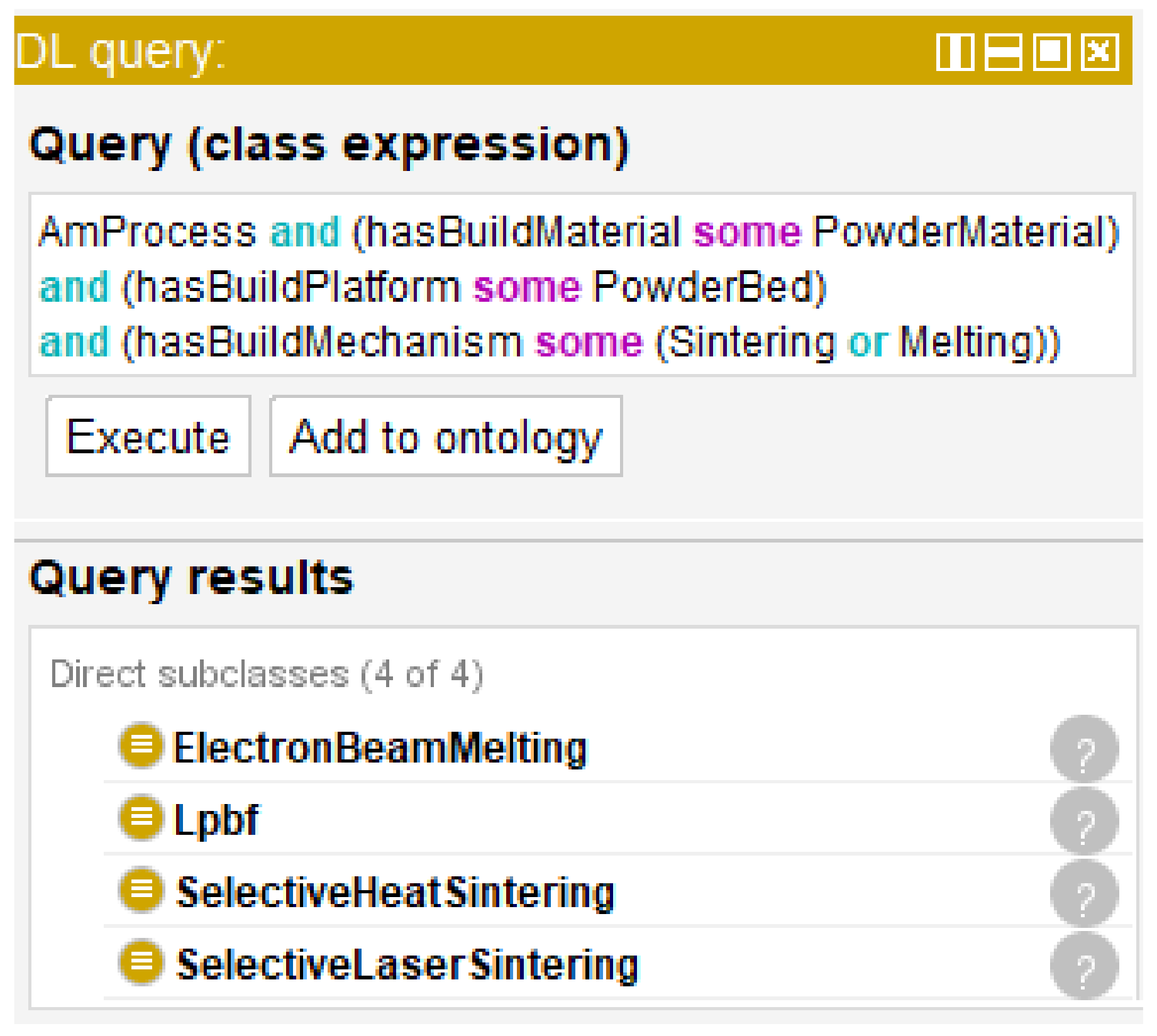
LPBF is an AM process whose energy source is a laser beam, build material is a powder material, build platform is a powder bed, and build mechanism is melting. Process planning for LPBF is a product realisation activity that aims to design appropriate process variables to build a part that can satisfy certain build and quality requirements. The main inputs of this activity include a 3D model, an LPBF material, an LPBF machine, and build and quality requirements. The outputs of the activity are a set of process variables, which include build orientation, support structure, slices, laser scanning path, and process parameters. Process planning consists of four successive tasks that of part orientation, that of support generation, that of model slicing, and that of path planning [55].
Based on the description above, twenty-eight top-level concepts were created and depicted in Figure 3. Among them, Lpbf, LpbfPart, LpbfMaterial, LpbfMachine, ProcessPlanning, PartOrientation, SupportGeneration, ModelSlicing, and PathPlanning are composite concepts (concepts that need to be defined by other concepts), while the remaining concepts are atomic concepts (concepts that cannot be defined by other concepts). The DL definitions of the nine composite concepts are given by the following terminological axioms:
L p b f A m P r o c e s s h a s E n e r g y S o u r c e . L a s e r B e a m h a s B u i l d M a t e r i a l . P o w d e r M a t e r i a l h a s B u i l d P l a t f o r m . P o w d e r B e d h a s B u i l d M e c h a n i s m . M e l t i n g
L p b f P a r t A m P a r t i s M a n u f a c t u r e d U s i n g . L p b f
L p b f M a t e r i a l P o w d e r M a t e r i a l i s A p p l i c a b l e F o r . L p b f
L p b f M a c h i n e A m M a c h i n e i s B a s e d O n . L p b f
P r o c e s s P l a n n i n g R e a l i s a t i o n A c t i v i t y h a s A i m O f D e s i g n i n g . P r o c e s s V a r i a b l e
P a r t O r i e n t a t i o n P r o c e s s P l a n n i n g h a s A i m O f D e s i g n i n g . B u i l d O r i e n t a t i o n
S u p p o r t G e n e r a t i o n P r o c e s s P l a n n i n g h a s A i m O f D e s i g n i n g . S u p p o r t S t r u c t u r e
M o d e l S l i c i n g P r o c e s s P l a n n i n g h a s A i m O f D e s i g n i n g . S l i c e
P a t h P l a n n i n g P r o c e s s P l a n n i n g h a s A i m O f D e s i g n i n g . L a s e r S c a n n i n g P a t h h a s A i m O f D e s i g n i n g . P r o c e s s P a r a m e t e r
where ≡ is the concept definition symbol in DLs which is used to define a concept, ∃ is the existential restriction symbol in DLs which is used to denote that there are one or more instances of a concept that have a specific relation, ⊓ is the concept conjunction symbol in DLs which is used to obtain the intersection of instances of two concepts, and hasEnergySource, hasBuildMaterial, hasBuildPlatform, hasBuildMechanism, hasAimOfDesigning, isManufacturedUsing, isApplicableFor, and isBasedOn are object relations whose domain, range, and meaning are listed in Table 3.
The build and quality requirements are specified by process planners based on certain indicators. Indicators for describing the build requirements of an LPBF part mainly include support volume, build time, and build cost, while indicators for specifying the quality requirements of an LPBF part mainly contain dimensional error, geometric error, volumetric error, surface roughness, density, hardness, yield strength, tensile strength, elongation, residual stress, and fatigue strength. In the process of planning for LPBF, the values of these indicators for an LPBF part to be built are usually predicted via certain prediction models. To describe indicator values, fourteen top-level data relations named hasSupportVolume-mm3, hasBuildTime-h, hasBuildCost-GBP, hasDimensionalError-mm, hasGeometricError-mm, hasVolumetricError-mm3, hasSurfaceRoughness-μm, hasDensity-g/cm3, hasHardness-HV, hasYieldStrength-MPa, hasTensileStrength-MPa, hasElongation-Pct, hasResidualStress-MPa, and hasFatigueStrength-MPa were created. The domain and range of each data relation are respectively LpbfPart and xsd:double. This means that an LPBF part has predicted indicator value of xsd:double.
The widely known LPBF materials include Ti6Al4V, AlSi10Mg, stainless steel, and tool steel. Recently, several other types of LPBF materials, such as tungsten, zinc alloy, magnesium alloy, and metal matrix composite, have been developed [56]. Therefore, eight assertional axioms were created as follows: LpbfMaterial(ti6Al4V); LpbfMaterial(alSi10Mg); LpbfMaterial(stainlessSteel); LpbfMaterial(toolSteel); LpbfMaterial(tungsten); LpbfMaterial(zincAlloy); LpbfMaterial(magnesiumAlloy); LpbfMaterial(metalMatrixComposite). According to the Senvol Database [54], there have been two hundred and thirty-six LPBF machines available in the market to date. The names of these LPBF machines were used to instantiate the concept LpbfMachine to create two hundred and thirty-six assertional axioms. For example, in the database, EOSINT M270 is an LPBF machine. An assertional axiom LpbfMachine(eosintM270) was created to make this assertion.

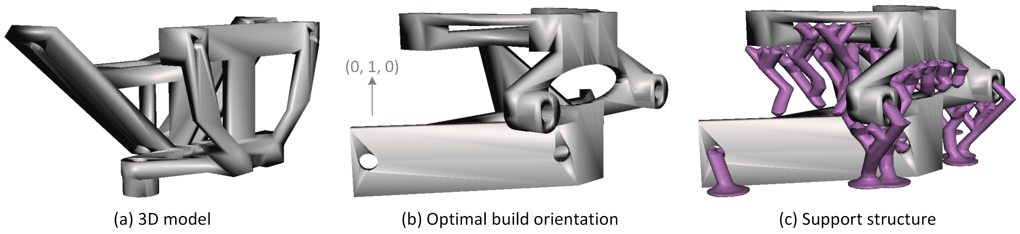
3.2. Entities for Part Orientation

Part orientation is a process planning task that aims to design a build orientation that best meets the build and quality requirements to build a part [
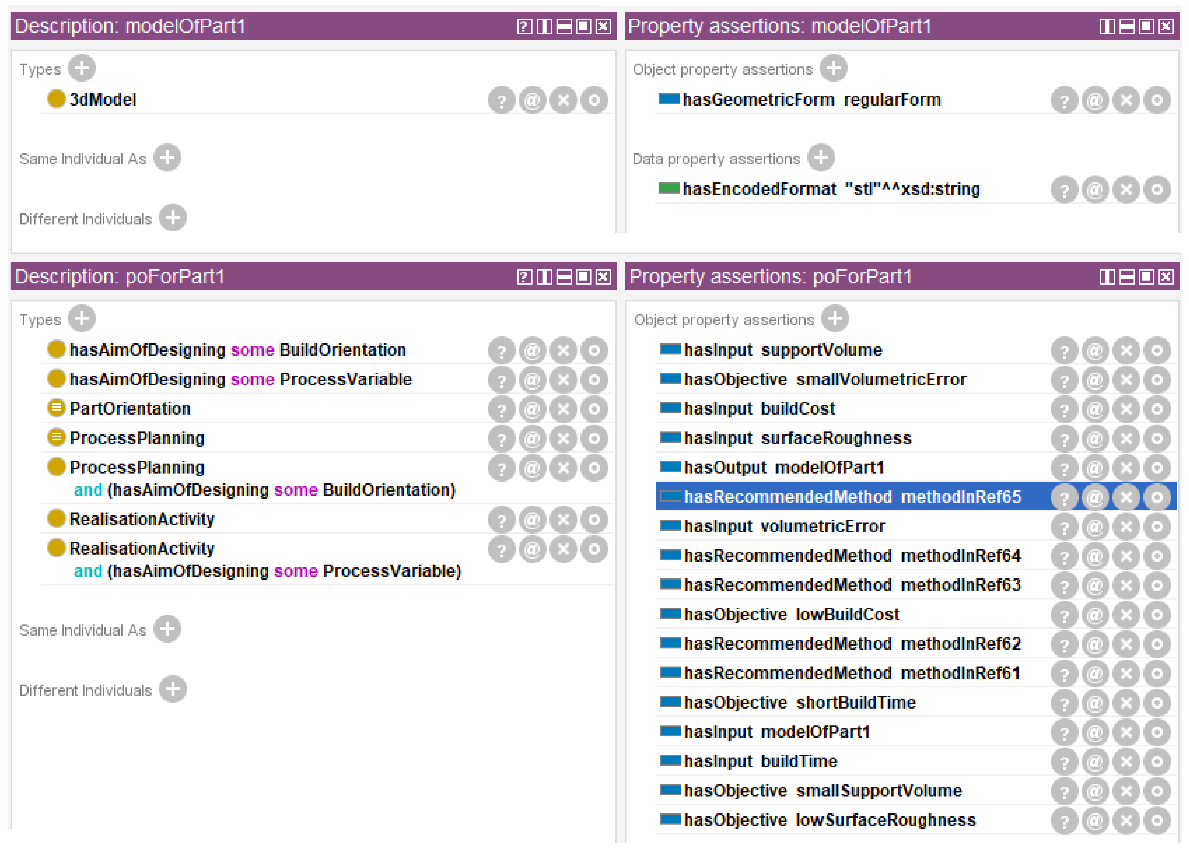
4]. The main inputs of this task include a 3D model of a part to be built and specific build and quality requirements on the part. Its output is a 3D model in a build orientation. The 3D model is the results of the design activity and generally encoded in a specific format [22], such as the STL (standard tessellation language) format, 3MF (3D manufacturing file) format, and AMF (additive manufacturing file) format.
Existing methods for part orientation can be classified into search-based methods and rule-based methods [4]. Search-based methods take the part orientation problem as a multi-objective optimisation problem. They usually adopts specific search algorithms, such as the random search algorithm [57], genetic algorithm [58], particle swarm algorithm [59], and iterative tabu search algorithm [60], to search an orientation that can optimise multiple objectives at the same time from infinite possible orientations. In search-based methods, a build orientation is generally expressed via an angle pair ( α , β ) , where the build orientation lines up along the +z axis after rotating the 3D model α ( 0 α 360 ) degrees around the x axis and β ( 0 β 360 ) degrees around the y axis. Search-based methods usually have relatively high accuracy and relatively low efficiency. They are generally applied to free-form surface models.
Rule-based methods take the part orientation problem as a multi-objective decision-making problem. It first generates a certain number of alternative orientations from infinite possible orientations via performing shape feature recognition [61,62] or triangular facet clustering [63,64,65] on the 3D model and carrying out rule-based reasoning according to the recognition or clustering results. Then, a multi-objective decision-making method is used to select an orientation from the alternative orientations that can satisfy multiple objectives at the same time. In rule-based methods, a build orientation is generally represented by a unit vector ( x , y , z ) . Rule-based methods are relatively efficient, since they do not spend time on many meaningless calculations. However, they are difficult to achieve desired accuracy on free-form surface models. They are more suitable for regular surface models.
Based on the analysis above, it is recommended to use a rule-based method for part orientation when the input 3D model is a regular surface model and to use a search-based method on a free-form surface model.
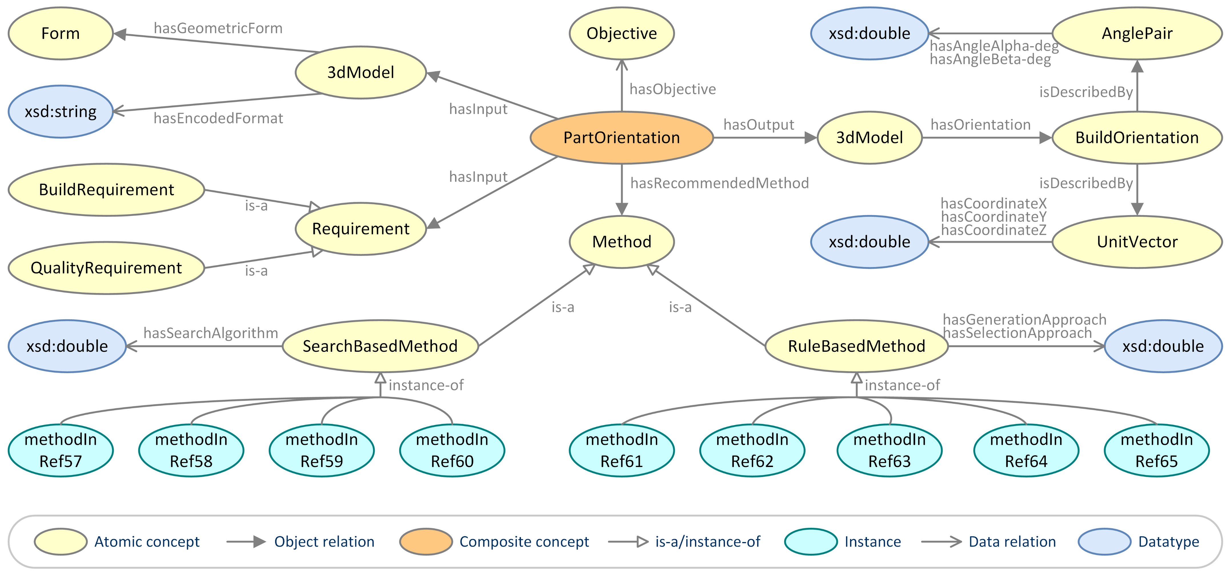
To represent the knowledge in part orientation, seven concepts named Objective, Method, SearchBasedMethod, RuleBasedMethod, AnglePair, UnitVector, and Form, sixteen relations listed in Table 4, four instances named methodInRef57, methodInRef58, methodInRef59, and methodInRef60 (instances of SearchBasedMethod), and five instances named methodInRef61, methodInRef62, methodInRef63, methodInRef64, and methodInRef65 (instances of RuleBasedMethod) were created. Based on these entities, an ontological view of part orientation for LPBF is delineated in Figure 4, and two SWRL rules for recommending a part orientation method for an input 3D model were developed as follows:
P a r t O r i e n t a t i o n ( ? x 1 ) 3 d M o d e l ( ? x 2 ) S e a r c h B a s e d M e t h o d ( ? x 3 ) h a s I n p u t ( ? x 1 , ? x 2 ) h a s G e o m e t r i c F o r m ( ? x 2 , f r e e F o r m ) h a s R e c o m m e n d e d M e t h o d ( ? x 1 , ? x 3 )
P a r t O r i e n t a t i o n ( ? x 1 ) 3 d M o d e l ( ? x 2 ) R u l e B a s e d M e t h o d ( ? x 3 ) h a s I n p u t ( ? x 1 , ? x 2 ) h a s G e o m e t r i c F o r m ( ? x 2 , r e g u l a r F o r m ) h a s R e c o m m e n d e d M e t h o d ( ? x 1 , ? x 3 )
where the statements on the left and right of → are respectively the antecedent and consequent of an SWRL rule, a n t e c e d e n t c o n s e q u e n t denotes that if the antecedent holds then the consequent holds, C i ( ? x j ) ( C i is a DL concept) or R i ( ? x j , ? x k ) ( R i is a DL relation) is an atom in an SWRL rule which is used to describe a condition, ∧ is the atom conjunction symbol in an SWRL rule which denotes ‘and’, each variable is marked using a question mark as its prefix, and freeForm and regularForm are instances of Form.

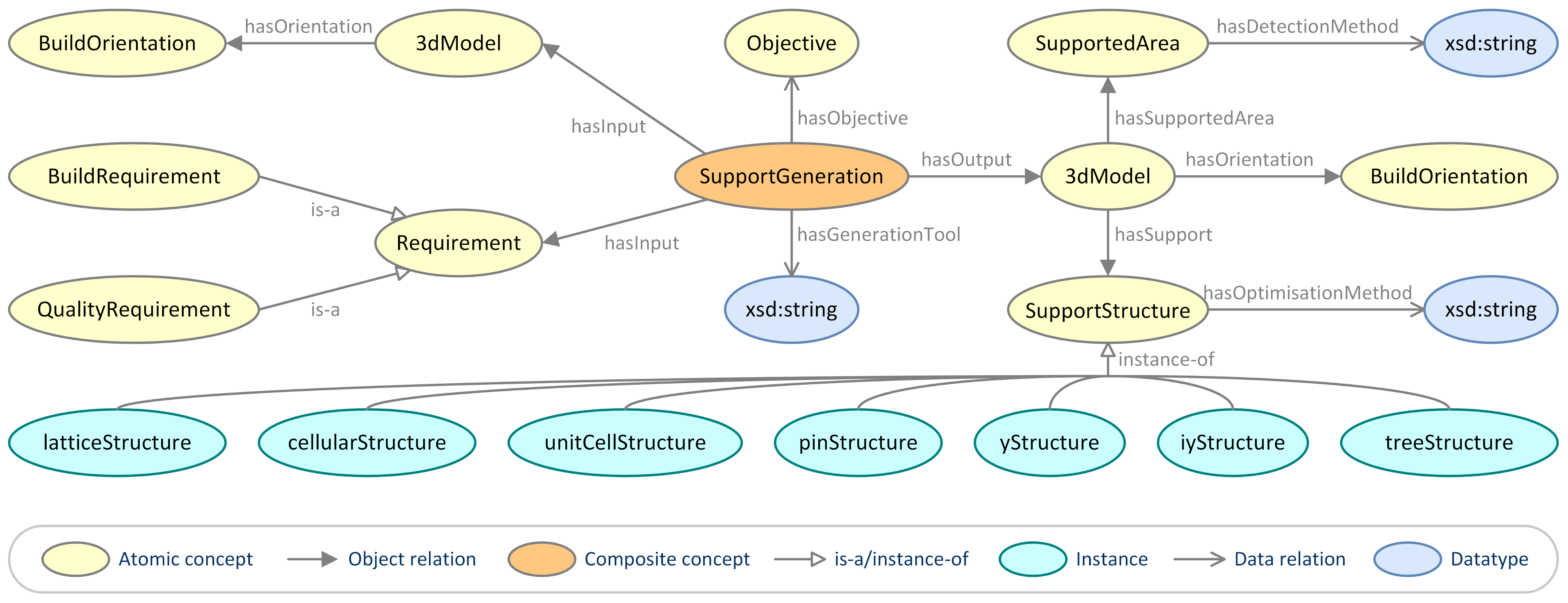
3.3. Entities for Support Generation

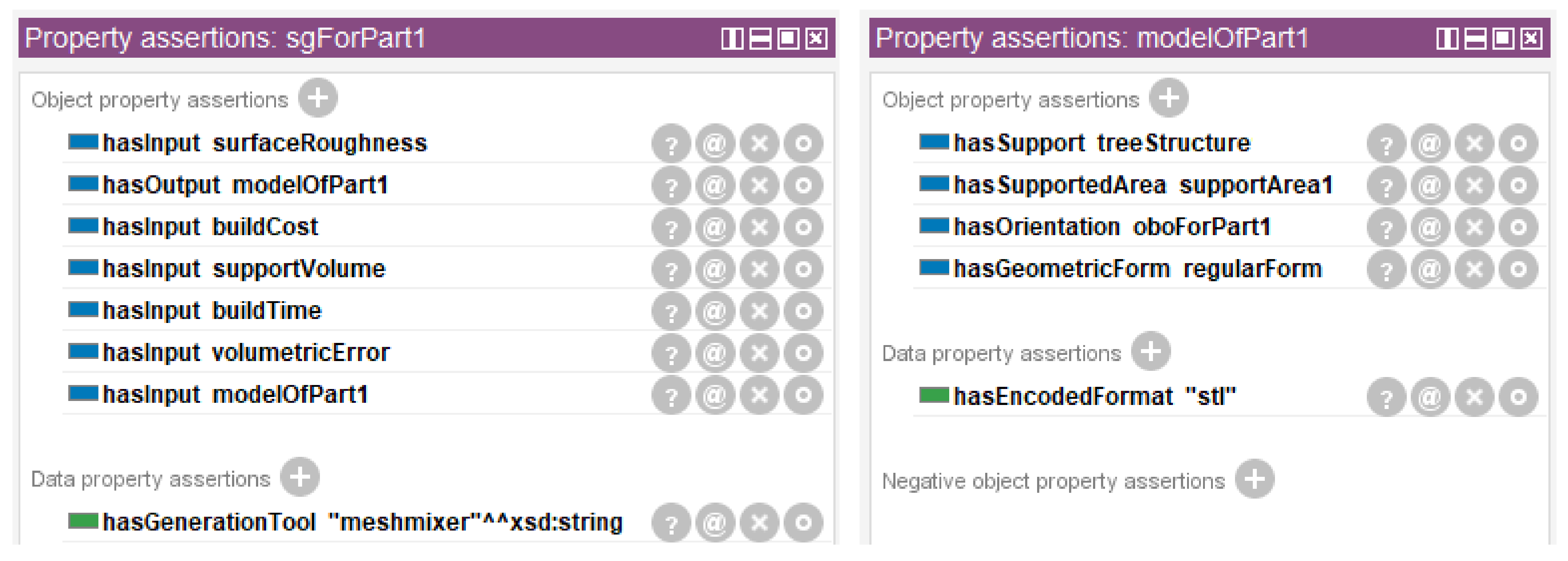
Support generation is a process planning task that aims to generate the minimum amount of support structure that best meets the build and quality requirements to build a part [5]. The main inputs of this task include a 3D model in a build orientation for a part to be built and specific build and quality requirements on the part. Its output is a 3D model with support structure in a build orientation.
To generate the support structure for a 3D model in a given build orientation, the first step is to detect the overhang area on the model that needs to be supported. In existing support generation methods, this detection is generally carried out using the angles between the normal vectors of triangular facets and the build orientation. When the angle corresponding to a triangular facet is greater than a certain value, the area corresponding to the triangular facet is considered to be the overhang area that needs to be supported [5].
After detecting the supported overhang area, a specific shape of support structure will be generated for it. So far, a number of different shapes of support structures for AM part build have been developed [5]. The support structures suitable for LPBF part build mainly include lattice support structure [66], cellular support structure [67], unit cell support structure [68], pin support structure [69], Y support structure [69], IY support structure [69], and tree support structure [70]. In practice, which shape of support structure to use is usually determined by the used process planning tool, since each process planning tool provides its specific shapes of support structures.
Support generation is usually coupled with optimising the selected shape of support structure to minimise its total volume and improve part quality. To date, many optimisation methods have ben presented within academia. For example, a lattice support structure optimisation method based on Taguchi experiment was presented in [71]; a lattice support structure optimisation framework based on genetic algorithm was established in [72]; in [59], a topology optimisation method was used to optimise lattice support structure to prevent residual stress induced build failure; in [73], the topology of lattice support structure is optimised to maximise its thermal conductivity and to mitigate the effect of thermal stress on the dimensional and geometric accuracy of an LPBF part; a method for optimising the topology of lattice support structure is presented in [74]; a hybrid optimisation framework for topology, build orientation, and support structure is established in [75]. These methods provide practical tools for optimisation of the support structure of an LPBF part. They can be selected according to specific optimisation objects and objectives.
To represent the knowledge in support generation, a concept named SupportedArea, five relations listed in Table 5, and seven instances named latticeStructure, cellularStructure, unitCellStructure, pinStructure, yStructure, iyStructure, and treeStructure (instances of SupportStructure) were created. Using these entities, an ontological view of support generation for LPBF is delineated in Figure 5.

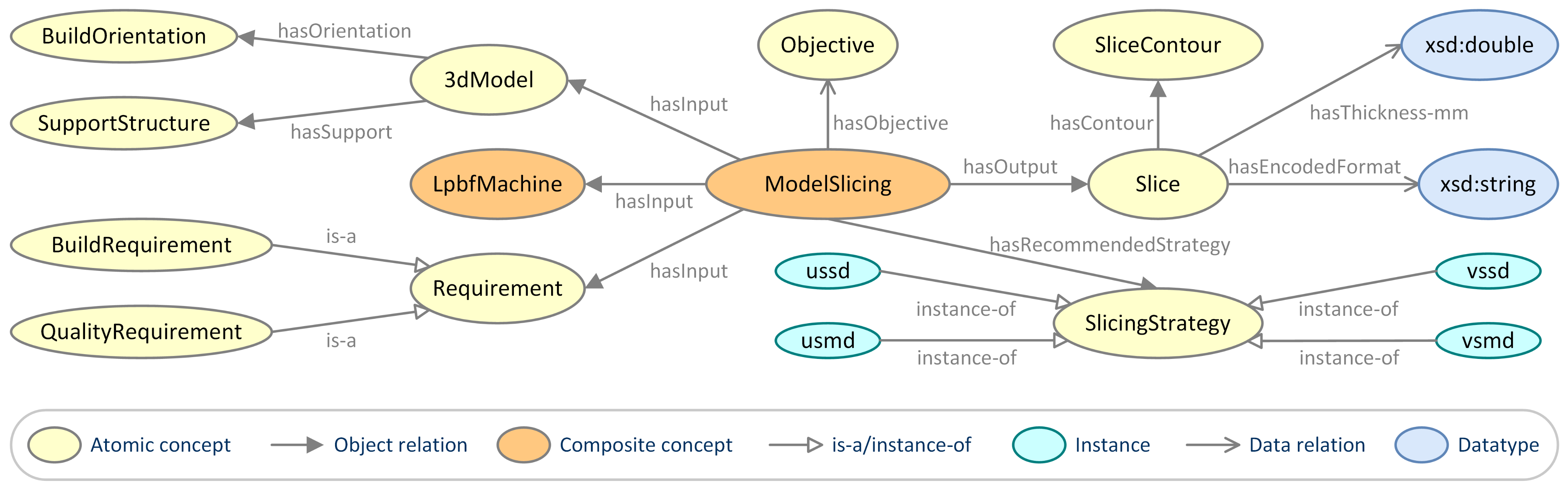
3.4. Entities for Model Slicing

Model slicing is a process planning task that aims to truncate the build model (i.e., a 3D model with support structure) into a set of thin slices that best meet the build and quality requirements to build a part [6]. The main inputs of this task include an LPBF machine, a 3D model with support structure in a build orientation for a part to be built, and specific build and quality requirements on the part. Its outputs are a set of thin slices. A slice corresponds to a layer of the part to be built. The main attributes of a slice are its contour and thickness. This thickness is usually called layer thickness, which is one of the critical LPBF process parameters. The output slice information is generally encoded in a proprietary format [22], such as the CLI (common layer interface), SLC (stereo lithography contour), and HPGL (Hewlett-Packard graphics language) format.
The simplest model slicing strategy is uniform slicing in single direction, which truncates the build model into a set of slices with equal thickness along the direction perpendicular to the build orientation. It is the first model slicing strategy in AM and is the most widely used strategy in industry [6]. The biggest advantage of the uniform slicing in single direction is that it is simple, efficient, and robust. However, this strategy would lead to a loss of control over the part accuracy, since it neglects the actual geometry of the build model [55].
In the past few years, a number of improvement strategies were developed [76,77,78], where representative ones are uniform slicing in multiple directions, variable slicing in single direction, and variable slicing in multiple directions. Each strategy has its specific characteristics. Generally, a slicing strategy is selected based on actual objectives [6]:
  • if the objectives of model slicing are normal accuracy and high efficiency, then uniform slicing in single direction (ussd) is recommended;
  • if the objectives of model slicing are normal accuracy, reduced support, and alleviated anisotropy, then uniform slicing in multiple directions (usmd) is recommended;
  • if the objective of model slicing is high accuracy, then variable slicing in single direction (vssd) is recommended;
  • if the objectives of model slicing are high accuracy, free of support, and alleviated anisotropy, then variable slicing in multiple directions (vsmd) is recommended.
To represent the knowledge in model slicing, two concepts named SliceContour and SlicingStrategy, three relations listed in Table 6, and four instances named ussd, usmd, vssd, and vsmd (instances of SlicingStrategy) were created. Based on these entities, an ontological view of model slicing for LPBF is delineated in Figure 6, and four SWRL rules for recommending a model slicing strategy were developed as follows:
M o d e l S l i c i n g ( ? x 1 ) h a s O b j e c t i v e ( ? x 1 , n o r m a l A c c u r a c y ) h a s O b j e c t i v e ( ? x 1 , h i g h E f f i c i e n c y ) h a s R e c o m m e n d e d S t r a t e g y ( ? x 1 , u s s d )
M o d e l S l i c i n g ( ? x 1 ) h a s O b j e c t i v e ( ? x 1 , n o r m a l A c c u r a c y ) h a s O b j e c t i v e ( ? x 1 , r e d u c e d S u p p o r t ) h a s O b j e c t i v e ( ? x 1 , a l l e v i a t e d A n i s o t r o p y ) h a s R e c o m m e n d e d S t r a t e g y ( ? x 1 , u s m d )
M o d e l S l i c i n g ( ? x 1 ) h a s O b j e c t i v e ( ? x 1 , h i g h A c c u r a c y ) h a s R e c o m m e n d e d S t r a t e g y ( ? x 1 , v s s d )
M o d e l S l i c i n g ( ? x 1 ) h a s O b j e c t i v e ( ? x 1 , h i g h A c c u r a c y ) h a s O b j e c t i v e ( ? x 1 , f r e e O f S u p p o r t ) h a s O b j e c t i v e ( ? x 1 , a l l e v i a t e d A n i s o t r o p y ) h a s R e c o m m e n d e d S t r a t e g y ( ? x 1 , v s m d )
where normalAccuracy, highEfficiency, reducedSupport, alleviatedAnisotropy, highAccuracy, and freeOfSupport are instances of Objective.

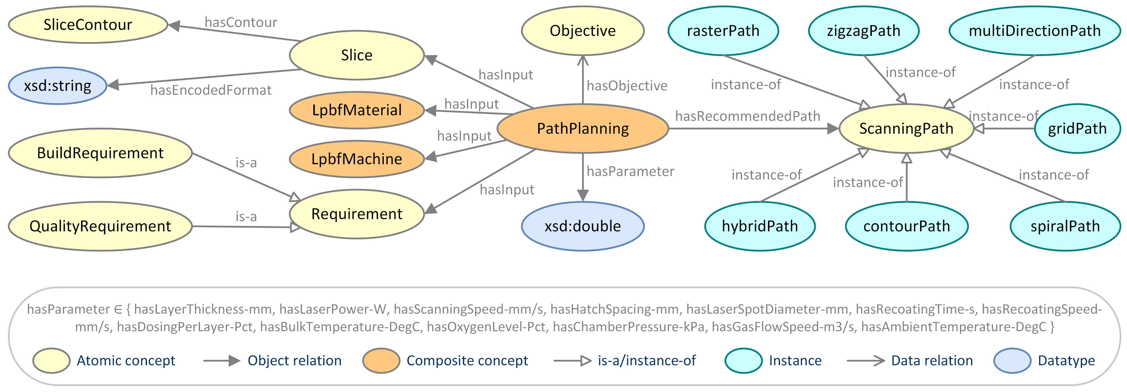
3.5. Entities for Path Planning

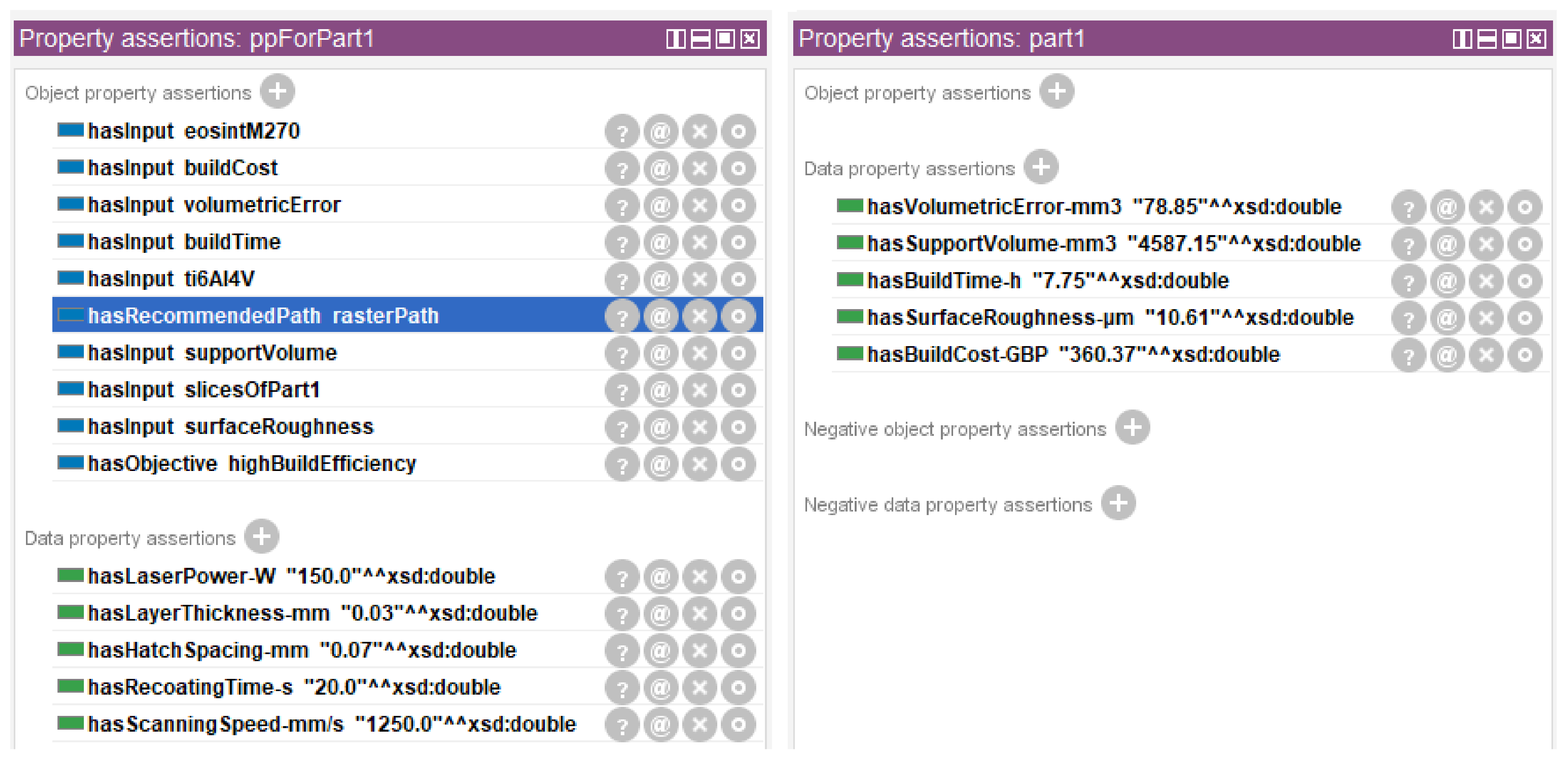
Path planning is a process planning task that aims to design a laser scanning path and a set of process parameters that best meets the build and quality requirements to build a part [6,7]. The main inputs of this task include an LPBF material, an LPBF machine, a set of slices for a part to be built, and specific build and quality requirements on the part. Its outputs are a laser scanning path and a set of process parameters.
An important step in path planning is to select or develop a proper laser scanning path. This step is affected by the adopted model slicing strategy. If a planar slicing strategy is adopted, alternative path patterns mainly include raster, zigzag, multi-direction, grid, spiral, contour, and hybrid paths. Each path has its specific strengths and shortcomings. In general, the path patterns are selected according to specific objectives [6]:
  • If the objective of path planning is high build efficiency, then raster path is recommended;
  • If the objectives of path planning are high build efficiency and high mechanical performance, then zigzag path or grid path is recommended;
  • If the objectives of path planning are high geometric accuracy and high mechanical performance, then multi-direction path or contour path is recommended;
  • If the objectives of path planning are high geometric accuracy, less path passes, less path elements, and high mechanical performance, then spiral path is recommended;
  • If the objectives of path planning are high build efficiency and high geometric accuracy, then hybrid path is recommended.
Another important step in path planning is to design a set of optimal process parameters. According to the study in [79], controllable process parameters include layer thickness, laser power, scanning speed, hatch spacing, recoating time, recoating speed, dosing per layer, bulk temperature, oxygen level, chamber pressure, gas flow speed, and ambient temperature. Among them, layer thickness, laser power, scanning speed, and hatch spacing are four critical process parameters. The volumetric energy density calculated from them is an important indicator to measure the effect of process parameters on part quality [80]. For design of process parameters, most of existing methods first generate a set of combinations of process parameters, then predict certain part quality indicators under each combination, and finally determine the optimal process parameters on the basis of the prediction results [8].
To represent the knowledge in path planning, an object relation named hasRecommendedPath, thirteen data relations named hasLayerThickness-mm, hasLaserPower-W, hasScanningSpeed-mm/s, hasHatchSpacing-mm, hasLaserSpotDiameter-mm, hasRecoatingTime-s, hasRecoatingSpeed-mm/s, hasDosingPerLayer-Pct, hasBulkTemperature-DegC, hasOxygenLevel-Pct, hasChamberPressure-kPa, hasGasFlowSpeed-m3/s, and hasAmbientTemperature-DegC, and seven instances named rasterPath, zigzagPath, multiDirectionPath, gridPath, spiralPath, contourPath, and hybridPath (instances of LaserScanningPath) were created. The domain and range of the object relation are respectively PathPlanning and ScanningPath. This means that a path planning task has designed laser scanning path of (a specific scanning path). The domain and range of each data relation are respectively PathPlanning and xsd:double. This means that a path planning task has designed process parameter value of xsd:double. Based on the crated entities, an ontological view of path planning for LPBF is delineated in Figure 7, and seven SWRL rules for recommending a laser scanning path were developed as follows:
P a t h P l a n n i n g ( ? x 1 ) h a s O b j e c t i v e ( ? x 1 , h i g h B u i l d E f f i c i e n c y ) h a s R e c o m m e n d e d P a t h ( ? x 1 , r a s t e r P a t h )
P a t h P l a n n i n g ( ? x 1 ) h a s O b j e c t i v e ( ? x 1 , h i g h B u i l d E f f i c i e n c y ) h a s O b j e c t i v e ( ? x 1 , h i g h M e c h a n i c a l P e r f o r m a n c e ) h a s R e c o m m e n d e d P a t h ( ? x 1 , z i g z a g P a t h )
P a t h P l a n n i n g ( ? x 1 ) h a s O b j e c t i v e ( ? x 1 , h i g h G e o m e t r i c A c c u r a c y ) h a s O b j e c t i v e ( ? x 1 , h i g h M e c h a n i c a l P e r f o r m a n c e ) h a s R e c o m m e n d e d P a t h ( ? x 1 , m u l t i D i r e c t i o n P a t h )
P a t h P l a n n i n g ( ? x 1 ) h a s O b j e c t i v e ( ? x 1 , h i g h B u i l d E f f i c i e n c y ) h a s O b j e c t i v e ( ? x 1 , h i g h M e c h a n i c a l P e r f o r m a n c e ) h a s R e c o m m e n d e d P a t h ( ? x 1 , g r i d P a t h )
P a t h P l a n n i n g ( ? x 1 ) h a s O b j e c t i v e ( ? x 1 , h i g h G e o m e t r i c A c c u r a c y ) h a s O b j e c t i v e ( ? x 1 , l e s s P a t h P a s s e s ) h a s O b j e c t i v e ( ? x 1 , l e s s P a t h E l e m e n t s ) h a s O b j e c t i v e ( ? x 1 , h i g h M e c h a n i c a l P e r f o r m a n c e ) h a s R e c o m m e n d e d P a t h ( ? x 1 , s p i r a l P a t h )
P a t h P l a n n i n g ( ? x 1 ) h a s O b j e c t i v e ( ? x 1 , h i g h G e o m e t r i c A c c u r a c y ) h a s O b j e c t i v e ( ? x 1 , h i g h M e c h a n i c a l P e r f o r m a n c e ) h a s R e c o m m e n d e d P a t h ( ? x 1 , c o n t o u r P a t h )
P a t h P l a n n i n g ( ? x 1 ) h a s O b j e c t i v e ( ? x 1 , h i g h B u i l d E f f i c i e n c y ) h a s O b j e c t i v e ( ? x 1 , h i g h G e o m e t r i c A c c u r a c y ) h a s R e c o m m e n d e d P a t h ( ? x 1 , h y b r i d P a t h )
where highBuildEfficiency, highMechanicalPerformance, highGeometricAccuracy, lessPathPasses, and lessPathElements are instances of Objective.

4. Application and Illustrations

4.1. Application of the Ontology

Process planning on an LPBF part is carried out to illustrate the application of the developed DL-based ontology. The 3D model of the part is encoded in the STL format and shown in Figure 8. This model is a regular form model, which was developed in [61]. It has 1181 vertices, 2426 triangular facets, total surface area of 9137.33 mm2, and total volume of 9603.15 mm3. The bounding box of the model has a length of 74.09 mm, a width of 33.75 mm, and a height of 34.34 mm. It is assumed that the part will be built using the LPBF material Ti6Al4V and the LPBF machine EOSINT M270. Before starting the actual part build, four process planning tasks on the part, part orientation, support generation, model slicing, and path planning, are needed to be completed successively. The objectives of part orientation are small support volume, short build time, low build cost, small volumetric error, and low surface roughness. The used support generation tool is Meshmixer. The objectives of model slicing are normal accuracy and high efficiency. The objective of path planning is high build efficiency.
The first task to be completed is part orientation. Based on the information above, two concept assertions 3dModel(modelOfPart1) and PartOrientation(poForPart1) and thirteen relation assertions for modelOfPart1 and poForPart1 shown in Figure 9 were first created. Then, five relation assertions for recommending a part orientation method, which are also shown in Figure 9, were generated after performing OWL/SWRL reasoning using the Drools reasoning engine. According to the reasoning results, the rule-based methods in [61,62,63,64,65] are recommended to perform part orientation. Here the rule-based method in [65] was used and the determined optimal build orientation under the five objectives is depicted in Figure 8. Based on this, two concept assertions BuildOrientation(oboForPart1) and UnitVector(unitVector1), a new relation assertion for poForPart1, and five relation assertions for modelOfPart1, oboForPart1, and unitVector1 shown in Figure 10 were generated in the ontology.
The second task to be completed is support generation. In this task, a concept assertion SupportGeneration(sgForPart1) and seven relation assertions shown in Figure 11 were first created. Then, support generation was carried out using Meshmixer and the generated support structure is depicted in Figure 8. Based on this, two new relation assertions for modelOfPart1 shown in Figure 11 were generated in the ontology.
The third task to be completed is model slicing. Firstly, a concept assertion ModelSlicing(msForPart1) and nine relation assertions shown in Figure 12 were created. Then, a relation assertion for recommending a model slicing strategy, which is also shown in Figure 12, was generated after performing OWL/SWRL reasoning using the Drools reasoning engine. According to the reasoning results, ussd (uniform slicing in single direction) can be selected to slice the build model with a thickness of 0.03 mm. Based on this, a new relation assertion for msForPart1 and three relation assertions for slicesOfPart1 shown in Figure 12 were generated in the ontology.
The last task to be completed is path planning. Firstly, a concept assertion PathPlanning(ppForPart1) and nine relation assertions shown in Figure 13 were created. Then, a relation assertion for recommending a laser scanning path, which is also shown in Figure 13, was generated after performing OWL/SWRL reasoning using the Drools reasoning engine. According to the reasoning results, raster path is selected to build the part under the following process parameters: layer thickness is 0.03 mm; laser power is 150 W; scanning speed is 1250 mm/s; hatch spacing is 0.07 mm; recoating time is 20 s; each of the remaining controllable process parameters takes its default value. Based on this, five new relation assertions for ppForPart1 shown in Figure 13 were generated in the ontology.
Based on all designed process variables above, the total support volume, total build time, total build cost, total volumetric error, and average surface roughness of the LPBF part were predicted using the prediction models in [81]: total support volume is 4587.15 mm3; total build time is 7.75 h; total build cost is 360.37 GBP; total volumetric error is 78.85 mm3; average surface roughness is 10.61 μm. Based on this, five new relation assertions for part1 shown in Figure 13 were generated in the ontology.

4.2. Illustrations of the Benefits

OWL DL can provide the strongest expressive capability under the premise of computational completeness and computational decidability, which enables reasoning mechanisms like consistency checking of the OWL DL ontology, knowledge reasoning on the ontology and semantic query from the ontology.
Consistency checking is performed to determine whether an instantiation of a concept satisfies the definition of the concept or would create an inconsistency. Using the HermiT reasoner in Protégé, the consistency of the developed ontology for LPBF process planning can be checked automatically. For example, if surfaceRoughness is further asserted as an instance of BuildRequirement in the ontology, then an inconsistency will be detected automatically, as shown in Figure 14, because BuildRequirement has been defined to be disjoint with QualityRequirement and the instance surfaceRoughness does not satisfy this definition. Once there are no inconsistencies in the developed ontology, knowledge reasoning can be performed on it.
Knowledge reasoning is carried out to reach new conclusions in a context based on the explicit knowledge in this context. In a DL-based ontology with SWRL rules, new knowledge can be inferred via either a DL reasoner or an SWRL reasoner. For example, the previous subsection has described the details of using the Drools reasoner (an SWRL reasoner integrated in Protégé) to reason out a recommended part orientation method, a recommended model slicing strategy, and a recommended laser scanning path in the developed ontology for LPBF process planning. After performing knowledge reasoning on the ontology, its an enriched version will become available for semantic query.
Semantic query is performed to search specific knowledge from an ontology. Three commonly used semantic query techniques for an OWL DL ontology with SWRL rules are DL query, SPARQL query, and SQWRL query, which respectively uses the reasoning mechanism of DL, SPARQL, and SQWRL to implement semantic query. For example, assume the following terminological axioms are defined in the developed ontology:
S e l e c t i v e L a s e r S i n t e r i n g A m P r o c e s s h a s E n e r g y S o u r c e . L a s e r B e a m h a s B u i l d M a t e r i a l . P o w d e r M a t e r i a l h a s B u i l d P l a t f o r m . P o w d e r B e d h a s B u i l d M e c h a n i s m . S i n t e r i n g
S e l e c t i v e H e a t S i n t e r i n g A m P r o c e s s h a s E n e r g y S o u r c e . T h e r m a l E n e r g y h a s B u i l d M a t e r i a l . P o w d e r M a t e r i a l h a s B u i l d P l a t f o r m . P o w d e r B e d h a s B u i l d M e c h a n i s m . S i n t e r i n g
E l e c t r o n B e a m M e l t i n g A m P r o c e s s h a s E n e r g y S o u r c e . E l e c t r o n B e a m h a s B u i l d M a t e r i a l . P o w d e r M a t e r i a l h a s B u i l d P l a t f o r m . P o w d e r B e d h a s B u i l d M e c h a n i s m . M e l t i n g
There is an AM process whose build material is a powder material, build platform is a powder bed, and build mechanism is sintering or melting. Someone needs to determine which specific AM processes it might belong to. If a common text search is adopted, no results will be obtained. However, if a DL query is carried out, the situation will be completely different. As shown in Figure 15, the description of the AM process is taken as the input of a DL query, and it can be inferred from the query results that the process might belong to selective laser sintering, selective heat sintering, electron beam melting, or LPBF.

5. Conclusions

In this paper, a DL-based ontology with SWRL rules for knowledge representation in process planning for LPBF is developed. Firstly, a set of top-level DL concepts, DL relations, DL instances, and DL axioms are created to represent the knowledge in general process planning activity. Then, specific DL concepts, DL relations, DL instances, and SWRL rules are respectively developed to describe the knowledge in part orientation, support generation, model slicing, and path planning. After that, the application of the developed ontology is demonstrated via process planning on an LPBF part. Finally, the benefits of the ontology are outlined and illustrated using examples. The illustration results show that the ontology has rigorous computer-interpretable semantics, which would lay solid basis for development of an LPBF process planning tool with autonomous decision-making capability.
Each of existing LPBF process planning tool has its specific knowledge representation method. Although ontology-based method has advantages in automatic consistency checking, knowledge reasoning, and semantic query and is gaining importance and popularity in AM knowledge representation, it should not be considered as a complete replacement of the methods used in existing tools, but more as an alternative method to improve them in some aspects. At present, existing ontologies for knowledge representation in LPBF are not yet mature. More powerful ontologies and related tools that can realise autonomous decision-making need to be further investigated.
Future work will aim especially at improving the developed DL-based ontology to overcome a main limitation: knowledge representation in process planning for multi-part production is not considered. An important feature of LPBF is that it enables rapid fabrication of multiple different parts in a mixed batch [60]. The developed ontology focuses on knowledge representation in process planning for production of one single part, it cannot be applied to the situation where multiple parts in the same build need to be planned simultaneously. From the perspective of application, it is of necessity and importance to improve the ontology to handle this situation. Further, the conventional LPBF process planning pipeline is somewhat complex and a simpler pipeline has been presented in [82]. It would be interesting to develop a DL-based ontology for this simpler pipeline.

Author Contributions

Conceptualisation, Z.L. and Y.Q.; methodology, Z.L. and Y.Q.; software, Z.L. and Y.Z.; validation, Z.L. and Y.Z.; writing—original draft, Z.L.; writing—review and editing, Z.L., M.H., Y.Z. and Y.Q.; supervision and funding acquisition, Y.Q. and M.H. All authors have read and agreed to the published version of the manuscript.

Funding

This work was supported by the National Natural Science Foundation of China (No. 52105511 and No. 51765012).

Institutional Review Board Statement

Not applicable.

Informed Consent Statement

Not applicable.

Data Availability Statement

Not applicable.

Conflicts of Interest

The authors declare that they have no conflict of interest.

Abbreviations

ABoxAssertion Box
AMAdditive Manufacturing
AMFAdditive Manufacturing File
CLICommon Layer Interface
DLDescription Logic
HPGLHewlett-Packard Graphics Language
LPBFLaser Powder Bed Fusion
OWLWeb Ontology Language
SLCStereo Lithography Contour
SPARQLSparql Protocol And Rdf Query Language
SQWRLSemantic Query-enhanced Web Rule Language
STLStandard Tessellation Language
SWRLSemantic Web Rule Language
TBoxTerminology Box
3DThree-Dimensional
3MF3D Manufacturing File
usmduniform slicing in multiple directions
ussduniform slicing in single direction
vsmdvariable slicing in multiple directions
vssdvariable slicing in single direction

References

  1. Gibson, I.; Rosen, D.; Stucker, B. Additive Manufacturing Technologies: 3D Printing, Rapid Prototyping, and Direct Digital Manufacturing, 2nd ed.; Springer: New York, NY, USA, 2015. [Google Scholar]
  2. Gu, D.; Shi, X.; Poprawe, R.; Bourell, D.L.; Setchi, R.; Zhu, J. Material-structure-performance integrated laser-metal additive manufacturing. Science 2021, 372, 1487. [Google Scholar] [CrossRef] [PubMed]
  3. Schmidt, M.; Merklein, M.; Bourell, D.; Dimitrov, D.; Hausotte, T.; Wegener, K.; Overmeyer, L.; Vollertsen, F.; Levy, G.N. Laser based additive manufacturing in industry and academia. CIRP Ann. 2017, 66, 561–583. [Google Scholar] [CrossRef]
  4. Qin, Y.; Qi, Q.; Shi, P.; Scott, P.J.; Jiang, X. Status, issues, and future of computer-aided part orientation for additive manufacturing. Int. J. Adv. Manuf. Technol. 2021, 115, 1295–1328. [Google Scholar] [CrossRef]
  5. Jiang, J.; Xu, X.; Stringer, J. Support Structures for Additive Manufacturing: A Review. J. Manuf. Mater. Process. 2018, 2, 64. [Google Scholar] [CrossRef] [Green Version]
  6. Zhao, D.; Guo, W. Shape and Performance Controlled Advanced Design for Additive Manufacturing: A Review of Slicing and Path Planning. J. Manuf. Sci. Eng. 2020, 142, 010801. [Google Scholar] [CrossRef]
  7. Jia, H.; Sun, H.; Wang, H.; Wu, Y.; Wang, H. Scanning strategy in selective laser melting (SLM): A review. Int. J. Adv. Manuf. Technol. 2021, 113, 2413–2435. [Google Scholar] [CrossRef]
  8. Shipley, H.; McDonnell, D.; Culleton, M.; Coull, R.; Lupoi, R.; O’Donnell, G.; Trimble, D. Optimisation of process parameters to address fundamental challenges during selective laser melting of Ti-6Al-4V: A review. Int. J. Mach. Tools Manuf. 2018, 128, 1–20. [Google Scholar] [CrossRef]
  9. Thompson, M.K.; Moroni, G.; Vaneker, T.; Fadel, G.; Campbell, R.I.; Gibson, I.; Bernard, A.; Schulz, J.; Graf, P.; Ahuja, B.; et al. Design for Additive Manufacturing: Trends, opportunities, considerations, and constraints. CIRP Ann. 2016, 65, 737–760. [Google Scholar] [CrossRef] [Green Version]
  10. Vaneker, T.; Bernard, A.; Moroni, G.; Gibson, I.; Zhang, Y. Design for additive manufacturing: Framework and methodology. CIRP Ann. 2020, 69, 578–599. [Google Scholar] [CrossRef]
  11. Baader, F.; Calvanese, D.; McGuinness, D.L.; Nardi, D.; Patel-Schneider, P.F. The Description Logic Handbook: Theory, Implementation and Applications; Cambridge University Press: Cambridge, UK, 2003. [Google Scholar]
  12. Gruber, T.R. A translation approach to portable ontology specifications. Knowl. Acquis. 1993, 5, 199–220. [Google Scholar] [CrossRef]
  13. Fortineau, V.; Paviot, T.; Lamouri, S. Improving the interoperability of industrial information systems with description logic-based models—The state of the art. Comput. Ind. 2013, 64, 363–375. [Google Scholar] [CrossRef]
  14. Kadiri, S.E.; Kiritsis, D. Ontologies in the context of product lifecycle management: State of the art literature review. Int. J. Prod. Res. 2015, 53, 5657–5668. [Google Scholar] [CrossRef]
  15. Qin, Y.; Lu, W.; Qi, Q.; Liu, X.; Zhong, Y.; Scott, P.J.; Jiang, X. Status, Comparison, and Issues of Computer-Aided Design Model Data Exchange Methods Based on Standardized Neutral Files and Web Ontology Language File. J. Comput. Inf. Sci. Eng. 2017, 17, 010801. [Google Scholar] [CrossRef]
  16. Qin, Y. Towards Intelligent Design of Tolerance Specifications: An Ontology-Based Methodology. Ph.D. Thesis, Huazhong University of Science and Technology, Wuhan, China, 2017. [Google Scholar]
  17. Horrocks, I.; Patel-Schneider, P.F.; Boley, H.; Tabet, S.; Grosof, B.; Dean, M. SWRL: A Semantic Web Rule Language Combining OWL and RuleML. 2014. Available online: https://www.w3.org/Submission/SWRL/ (accessed on 1 March 2022).
  18. McGuinness, D.L.; Harmelen, F.V. OWL Web Ontology Language Overview. 2004. Available online: https://www.w3.org/TR/owl-features/ (accessed on 1 March 2022).
  19. Prud’hommeaux, E.; Seaborne, A. SPARQL Query Language for RDF. 2008. Available online: https://www.w3.org/TR/rdf-sparql-query/ (accessed on 1 March 2022).
  20. O’Connor, M.J.; Das, A.K. SQWRL: A Query Language for OWL. In Proceedings of the 6th International Workshop on OWL: Experiences and Directions (OWLED 2009), Chantilly, VA, USA, 23–24 October 2009. [Google Scholar]
  21. Chandrasegaran, S.K.; Ramani, K.; Sriram, R.D.; Horváth, I.; Bernard, A.; Harik, R.F.; Gao, W. The evolution, challenges, and future of knowledge representation in product design systems. Comput.-Aided Des. 2013, 45, 204–228. [Google Scholar] [CrossRef]
  22. Qin, Y.; Qi, Q.; Scott, P.J.; Jiang, X. Status, comparison, and future of the representations of additive manufacturing data. Comput.-Aided Des. 2019, 111, 44–64. [Google Scholar] [CrossRef]
  23. Ranjan, R.; Samant, R.; Anand, S. Design for Manufacturability in Additive Manufacturing Using a Graph Based Approach. In Proceedings of the ASME 2015 International Manufacturing Science and Engineering Conference, Charlotte, NC, USA, 8–12 June 2015. [Google Scholar]
  24. Ko, H.; Moon, S.K.; Otto, K.N. Design knowledge representation to support personalised additive manufacturing. Virtual Phys. Prototyp. 2015, 10, 217–226. [Google Scholar] [CrossRef]
  25. Mokhtarian, H.; Coatanéa, E.; Paris, H.; Ritola, T.; Ellman, A.; Vihinen, J.; Koskinen, K.; Ikkala, K. A Network Based Modelling Approach Using the Dimensional Analysis Conceptual Modeling (DACM) Framework for Additive Manufacturing Technologies. In Proceedings of the ASME 2016 International Design Engineering Technical Conferences and Computers and Information in Engineering Conference, Charlotte, NC, USA, 21–24 August 2016. [Google Scholar]
  26. Feng, S.C.; Witherell, P.; Ameta, G.; Kim, D.B. Activity model for homogenization of data sets in laser-based powder bed fusion. Rapid Prototyp. J. 2017, 23, 137–148. [Google Scholar] [CrossRef]
  27. Booth, J.W.; Alperovich, J.; Chawla, P.; Ma, J.; Reid, T.N.; Ramani, K. The Sesign for Additive Manufacturing Worksheet. J. Mech. Des. 2017, 139, 100904. [Google Scholar] [CrossRef] [Green Version]
  28. Jee, H.; Witherell, P. A method for modularity in design rules for additive manufacturing. Rapid Prototyp. J. 2017, 23, 1107–1118. [Google Scholar] [CrossRef]
  29. Wang, Y.; Blache, R.; Zheng, P.; Xu, X. A Knowledge Management System to Support Design for Additive Manufacturing Using Bayesian Networks. J. Mech. Des. 2018, 140, 051701. [Google Scholar] [CrossRef]
  30. Qi, Q.; Pagani, L.; Scott, P.J.; Jiang, X. A categorical framework for formalising knowledge in additive manufacturing. Procedia CIRP 2018, 75, 87–91. [Google Scholar] [CrossRef]
  31. Yim, S.; Rosen, D.W. Case-Based Retrieval Approach of Supporting Process Planning in Layer-Based Additive Manufacturing. In Proceedings of the ASME 2007 International Design Engineering Technical Conferences and Computers and Information in Engineering Conference, Las Vegas, NV, USA, 4–7 September 2007. [Google Scholar]
  32. Yim, S.; Rosen, D.W. A repository for DFM problems using description logics. J. Manuf. Technol. Manag. 2008, 19, 755–774. [Google Scholar] [CrossRef]
  33. Liu, X.; Rosen, D.W. Ontology Based Knowledge Modelling and Reuse Approach of Supporting Process Planning in Layer-Based Additive Manufacturing. In Proceedings of the 2010 International Conference on Manufacturing Automation, Hong Kong, China, 13–15 December 2010. [Google Scholar]
  34. Witherell, P.; Feng, S.; Simpson, T.W.; John, D.B.S.; Michaleris, P.; Liu, Z.-K.; Chen, L.-Q.; Martukanitz, R. Toward Metamodels for Composable and Reusable Additive Manufacturing Process Models. J. Manuf. Sci. Eng. 2014, 136, 061025. [Google Scholar] [CrossRef]
  35. Eddy, D.; Krishnamurty, S.; Grosse, I.; Perham, M.; Wileden, J.; Ameri, F. Knowledge Management with an Intelligent Tool for Additive Manufacturing. In Proceedings of the ASME 2015 International Design Engineering Technical Conferences and Computers and Information in Engineering Conference, Boston, MA, USA, 2–5 August 2015. [Google Scholar]
  36. Roh, B.-M.; Kumara, S.R.; Simpson, T.W.; Michaleris, P.; Witherell, P.; Assouroko, I. Ontology-Based Laser and Thermal Metamodels for Metal-Based Additive Manufacturing. In Proceedings of the ASME 2016 International Design Engineering Technical Conferences and Computers and Information in Engineering Conference, Charlotte, NC, USA, 21–24 August 2016. [Google Scholar]
  37. Lu, Y.; Witherell, P.; Lopez, F.; Assouroko, I. Digital Solutions for Integrated and Collaborative Additive Manufacturing. In Proceedings of the ASME 2016 International Design Engineering Technical Conferences and Computers and Information in Engineering Conference, Charlotte, NC, USA, 21–24 August 2016. [Google Scholar]
  38. Assouroko, I.; Lopez, F.; Witherell, P. A Method for Characterizing Model Fidelity in Laser Powder Bed Fusion Additive Manufacturing. In Proceedings of the ASME 2016 International Mechanical Engineering Congress and Exposition, Phoenix, AZ, USA, 11–17 November 2016. [Google Scholar]
  39. Dinar, M.; Rosen, D.W. A Design for Additive Manufacturing Ontology. J. Comput. Inf. Sci. Eng. 2017, 17, 021013. [Google Scholar] [CrossRef]
  40. Kim, S.; Rosen, D.W.; Witherell, P.; Ko, H. Linking part design to process planning by design for additive manufacturing ontology. In Proceedings of the 3rd International Conference on Progress in Additive Manufacturing, Singapore, 14–17 May 2018; pp. 303–308. [Google Scholar]
  41. Hagedorn, T.J.; Krishnamurty, S.; Grosse, I.R. A Knowledge-Based Method for Innovative Design for Additive Manufacturing Supported by Modular Ontologies. J. Comput. Inf. Sci. Eng. 2018, 18, 021009. [Google Scholar] [CrossRef] [Green Version]
  42. Liang, J.S. An ontology-oriented knowledge methodology for process planning in additive layer manufacturing. Robot. Comput. Integr. Manuf. 2018, 53, 28–44. [Google Scholar] [CrossRef]
  43. Kim, S.; Rosen, D.W.; Witherell, P.; Ko, H. A Design for Additive Manufacturing Ontology to Support Manufacturability Analysis. J. Comput. Inf. Sci. Eng. 2019, 19, 041014. [Google Scholar] [CrossRef]
  44. Sanfilippo, E.M.; Belkadi, F.; Bernard, A. Ontology-based knowledge representation for additive manufacturing. Comput. Ind. 2019, 109, 182–194. [Google Scholar] [CrossRef]
  45. Ali, M.M.; Rai, R.; Otte, J.N.; Smith, B. A product life cycle ontology for additive manufacturing. Comput. Ind. 2019, 105, 191–203. [Google Scholar]
  46. Xiong, Y.; Dharmawan, A.G.; Tang, Y.; Foong, S.; Soh, G.S.; Rosen, D.W. A knowledge-based process planning framework for wire arc additive manufacturing. Adv. Eng. Inform. 2020, 45, 101135. [Google Scholar] [CrossRef]
  47. Ko, H.; Witherell, P.; Lu, Y.; Kim, S.; Rosen, D.W. Machine learning and knowledge graph based design rule construction for additive manufacturing. Addit. Manuf. 2021, 37, 101620. [Google Scholar] [CrossRef]
  48. Chen, R.; Lu, Y.; Witherell, P.; Simpson, T.W.; Kumara, S.; Yang, H. Ontology-Driven Learning of Bayesian Network for Causal Inference and Quality Assurance in Additive Manufacturing. IEEE Robot. Autom. Lett. 2021, 6, 6032–6038. [Google Scholar] [CrossRef]
  49. Roh, B.-M.; Kumara, S.R.; Witherell, P.; Simpson, T.W. Ontology-based process map for metal additive manufacturing. J. Mater. Eng. Perform. 2021, 30, 8784–8797. [Google Scholar] [CrossRef]
  50. Mayerhofer, M.; Lepuschitz, W.; Hoebert, T.; Merdan, M.; Schwentenwein, M.; Strasser, T.I. Knowledge-driven manufacturability analysis for additive manufacturing. IEEE Open J. Ind. Electron. Soc. 2021, 2, 207–223. [Google Scholar] [CrossRef]
  51. Jarrar, Q.; Belkadi, F.; Bernard, A. A Knowledge-Based Approach for Decision Support System in Additive Manufacturing. In Proceedings of the IFIP 2021 International Conference on Advances in Production Management Systems, Nantes, France, 5–9 September 2021; pp. 319–327. [Google Scholar]
  52. Park, H.; Ko, H.; Lee, Y.-T.T.; Feng, S.; Witherell, P.; Cho, H. Collaborative knowledge management to identify data analytics opportunities in additive manufacturing. J. Intell. Manuf. 2021. [Google Scholar] [CrossRef]
  53. Musen, M.A. The Protégé Project: A Look Back and a Look Forward. AI Matters 2015, 1, 4–12. [Google Scholar] [CrossRef]
  54. Senvol LLC. Senvol Database: Industrial Additive Manufacturing Machines and Materials. 2021. Available online: http://senvol.com/database/ (accessed on 1 March 2022).
  55. Kulkarni, P.; Marsan, A.; Dutta, D. A review of process planning techniques in layered manufacturing. Rapid Prototyp. J. 2000, 6, 18–35. [Google Scholar] [CrossRef]
  56. Sing, S.L.; Yeong, W.Y. Laser powder bed fusion for metal additive manufacturing: Perspectives on recent developments. Virtual Phys. Prototyp. 2020, 15, 359–370. [Google Scholar] [CrossRef]
  57. Chowdhury, S.; Mhapsekar, K.; Anand, S. Part Build Orientation Optimization and Neural Network-Based Geometry Compensation for Additive Manufacturing Process. J. Manuf. Sci. Eng. 2018, 140, 031009. [Google Scholar] [CrossRef]
  58. Brika, S.E.; Zhao, Y.F.; Brochu, M.; Mezzetta, J. Multi-Objective Build Orientation Optimization for Powder Bed Fusion by Laser. J. Manuf. Sci. Eng. 2017, 139, 111011. [Google Scholar] [CrossRef]
  59. Cheng, L.; To, A. Part-scale build orientation optimization for minimizing residual stress and support volume for metal additive manufacturing: Theory and experimental validation. Comput. Aided Des. 2019, 113, 1–23. [Google Scholar] [CrossRef]
  60. Griffiths, V.; Scanlan, J.P.; Eres, M.H.; Martinez-Sykora, A.; Chinchapatnam, P. Cost-driven build orientation and bin packing of parts in Selective Laser Melting (SLM). Eur. J. Oper. Res. 2019, 273, 334–352. [Google Scholar] [CrossRef] [Green Version]
  61. Zhang, Y.; Bernard, A.; Gupta, R.K.; Harik, R. Feature based building orientation optimization for additive manufacturing. Rapid Prototyp. J. 2016, 22, 358–376. [Google Scholar] [CrossRef]
  62. Al-Ahmari, A.M.; Abdulhameed, O.; Khan, A.A. An automatic and optimal selection of parts orientation in additive manufacturing. Rapid Prototyp. J. 2018, 24, 698–708. [Google Scholar] [CrossRef]
  63. Zhang, Y.; Harik, R.; Fadel, G.; Bernard, A. A statistical method for build orientation determination in additive manufacturing. Rapid Prototyp. J. 2019, 25, 187–207. [Google Scholar] [CrossRef]
  64. Qin, Y.; Qi, Q.; Shi, P.; Scott, P.J.; Jiang, X. Automatic generation of alternative build orientations for laser powder bed fusion based on facet clustering. Virtual Phys. Prototyp. 2020, 15, 307–324. [Google Scholar] [CrossRef]
  65. Qin, Y.; Qi, Q.; Shi, P.; Scott, P.J.; Jiang, X. Automatic determination of part build orientation for laser powder bed fusion. Virtual Phys. Prototyp. 2021, 16, 29–49. [Google Scholar] [CrossRef]
  66. Hussein, A.; Hao, L.; Yan, C.; Everson, R.; Young, P. Advanced lattice support structures for metal additive manufacturing. J. Mater. Process. Technol. 2013, 213, 1019–1026. [Google Scholar] [CrossRef]
  67. Strano, G.; Hao, L.; Everson, R.M.; Evans, K.E. A new approach to the design and optimisation of support structures in additive manufacturing. Int. J. Adv. Manuf. Technol. 2013, 66, 1247–1254. [Google Scholar] [CrossRef]
  68. Vaidya, R.; Aanand, S. Optimum support structure generation for additive manufacturing using unit cell structures and support removal constraint. Procedia Manuf. 2016, 5, 1043–1059. [Google Scholar] [CrossRef] [Green Version]
  69. Gan, M.X.; Wong, C.H. Practical support structures for selective laser melting. J. Mater. Process. Technol. 2016, 238, 474–484. [Google Scholar] [CrossRef]
  70. Zhu, L.; Feng, R.; Xi, J.; Li, P.; Wei, X. A Lightweight Design of Tree-shaped Support Structures for SLM Additive Manufacturing. Comput. Aided Des. Appl. 2020, 17, 716–726. [Google Scholar] [CrossRef]
  71. Calignano, F. Design optimization of supports for overhanging structures in aluminum and titanium alloys by selective laser melting. Mater. Des. 2014, 64, 203–213. [Google Scholar] [CrossRef]
  72. Vaissier, B.; Pernot, J.-P.; Chougrani, L.; Véron, P. Genetic-algorithm based framework for lattice support structure optimization in additive manufacturing. Comput.-Aided Des. 2019, 110, 11–23. [Google Scholar] [CrossRef]
  73. Huang, R.; Dai, N.; Cheng, X.; Wang, L. Topology optimization of lattice support structures for heat conduction in selective laser melting. Int. J. Adv. Manuf. Technol. 2020, 109, 1841–1851. [Google Scholar] [CrossRef]
  74. Pellens, J.; Lombaert, G.; Michiels, M.; Craeghs, T.; Schevenels, M. Topology optimization of support structure layout in metal-based additive manufacturing accounting for thermal deformations. Struct. Multidiscip. Optim. 2020, 61, 2291–2303. [Google Scholar] [CrossRef]
  75. Langelaar, M. Combined optimization of part topology, support structure layout and build orientation for additive manufacturing. Struct. Multidiscip. Optim. 2018, 57, 1985–2004. [Google Scholar] [CrossRef] [Green Version]
  76. Lefebvre, S. IceSL: A GPU accelerated CSG modeler and slicer. In Proceedings of the 18th European Forum on Additive Manufacturing, Paris, France, 25–27 June 2013. [Google Scholar]
  77. Steuben, J.C.; Iliopoulos, A.P.; Michopoulos, J.G. Towards Multiscale Topology Optimization for Additively Manufactured Components Using Implicit Slicing. In Proceedings of the ASME 2017 International Design Engineering Technical Conferences and Computers and Information in Engineering Conference, Cleveland, OH, USA, 6–9 August 2017. [Google Scholar]
  78. Adams, D.; Turner, C.J. An implicit slicing method for additive manufacturing processes. Virtual Phys. Prototyp. 2018, 13, 2–7. [Google Scholar] [CrossRef]
  79. Liu, C.; Roux, L.L.; Körner, C.; Tabaste, O.; Lacan, F.; Bigot, S. Digital twin-enabled collaborative data management for metal additive manufacturing systems. J. Manuf. Syst. 2022, 62, 857–874. [Google Scholar] [CrossRef]
  80. Khorasani, A.; Gibson, I.; Awan, U.S.; Ghaderi, A. The effect of SLM process parameters on density, hardness, tensile strength and surface quality of Ti-6Al-4V. Addit. Manuf. 2019, 25, 176–186. [Google Scholar] [CrossRef]
  81. Qin, Y. Automatic Determination of Part Build Orientation for Laser Powder Bed Fusion Additive Manufacturing. Ph.D. Thesis, University of Huddersfield, Huddersfield, UK, 2021. [Google Scholar]
  82. Haseltalab, V.; Dolen, M.; Yaman, U.; Hoffmann, C. Toward a Simple Design and Manufacturing Pipeline for Additive Manufacturing. IEEE Access 2021, 9, 107224–107234. [Google Scholar] [CrossRef]
Figure 2. Schematic diagram of the development process of the DL-based ontology.
Applsci 12 04612 g002
Figure 3. Graphical representation of top-level concepts and their hierarchies.
Applsci 12 04612 g003
Figure 4. An ontological view of part orientation for LPBF.
Applsci 12 04612 g004
Figure 5. An ontological view of support generation for LPBF.
Applsci 12 04612 g005
Figure 6. An ontological view of model slicing for LPBF.
Applsci 12 04612 g006
Figure 7. An ontological view of path planning for LPBF.
Applsci 12 04612 g007
Figure 8. 3D model, optimal build orientation, and support structure of an LPBF part.
Applsci 12 04612 g008
Figure 9. Assertions and reasoning results of part orientation for the LPBF part.
Applsci 12 04612 g009
Figure 10. Results of part orientation for the LPBF part in the ontology.
Applsci 12 04612 g010
Figure 11. Results of support generation for the LPBF part in the ontology.
Applsci 12 04612 g011
Figure 12. Results of model slicing for the LPBF part in the ontology.
Applsci 12 04612 g012
Figure 13. Results of path planning for the LPBF part in the ontology.
Applsci 12 04612 g013
Figure 14. Example of consistency checking of the ontology.
Applsci 12 04612 g014
Figure 15. Example of a DL query from the ontology.
Applsci 12 04612 g015
Table 1. Overview of existing models for AM knowledge representation.
Ref.YearRepresentation MethodSpecific AM Knowledge That Is Represented in the Constructed ModelProcess
[23]2015GraphsDesign guidelines for AMAM
[24]2015Finite state automataAM design knowledge for supporting personalised AMAM
[25]2016NetworksProcess functions and causal relationships between process variablesDMD
[26]2017FMLProcess-related data and knowledge in LPBFLPBF
[27]2017WorksheetGuidelines of design for AM for novice and intermittent usersAM
[28]2017Formal rulesDesign rules with modularity for AMAM
[29]2018Bayesian networksKnolwedge in design for AMAM
[30]2018Category theoryGeneral knowledge in design and process control for PBFPBF
Notes: DMD stands for direct material deposition; FML stands for function modelling language; PBF stands for powder bed fusion.
Table 2. Overview of existing ontologies for AM knowledge representation.
Ref.YearLanguagesSpecific AM Knowledge That Is Represented in the Constructed OntologyProcess
[31]2007DLDesign requirements, process plans, and rules that map requirements to plansAM
[32]2008DLDesign requirements, process plans, and rules that map requirements to plansAM
[33]2010DLDesign features and rules for selecting manufacturing variablesAM
[34]2014OWLKnowledge in development for AM processesLPBF
[35]2015OWL, SWRLMost applicable concepts of AM relevant to process planning applicationsAM
[36]2016OWLLaser and thermal metamodels for LPBFLPBF
[37]2016OWLInformation correlating material, design, and manufacturing operationsAM
[38]2016OWLModel fidelity in LPBFLPBF
[39]2017OWL, SWRLKnowledge in design for AMAM
[40]2018OWLDesign features, manufacturing features, and process parametersAM
[41]2018OWLInformation about innovative uses of AM technologiesAM
[42]2018——Knowledge in process planning for AMAM
[43]2019OWL, SWRLKnowledge in design for AMAM
[44]2019OWL, SWRLData and knowledge in AM value chainAM
[45]2019OWLKnowledge in AM product lifecycleAM
[46]2020——Metamodels and planning rules in process planning for wire arc AMWAAM
[47]2021OWL, SWRLKnowledge for LPBF design rule constructionLPBF
[48]2021——Causal relations between AM parameters and quality assurance requirementsLPBF
[49]2021OWLProcess parameters, physical models, thermal models, and build qualitiesLPBF
[50]2021OWLInformation about the capabilities of LCM process, printers and materialsLCM
[51]2021OWL, SWRLKnowledge for cost estimation in AMAM
[52]2021OWL, SWRLKnowledge for identifying and prioritising data analytics opportunities in AMLPBF
Notes: LCM stands for lithography-based ceramic manufacturing; WAAM stands for wire arc additive manufacturing.
Table 3. Domain, range, and meaning of eight top-level object relations.
Object RelationDomainRangeMeaning
hasEnergySourceAmProcessLaserBeamAn AM process that has energy source of
hasBuildMaterialAmProcessPowderMaterialAn AM process that has build material of
hasBuildPlatformAmProcessPowderBedAn AM process that has build platform of
hasBuildMechanismAmProcessMeltingAn AM process that has build mechanism of
hasAimOfDesigningRealisationActivityProcessVariableA realisation activity that has aim of designing
isManufacturedUsingAmPartLpbfAn AM part that is manufactured using
isApplicableForPowderMaterialLpbfA powder material that is applicable for
isBasedOnAmMachineLpbfAn AM machine that is based on
Table 4. Domain, range, and meaning of sixteen relations in part orientation.
Data RelationDomainRangeMeaning
hasInputProcessPlanningowl:ThingA process planning task that has input of
hasOutputProcessPlanningowl:ThingA process planning task that has output of
hasSearchAlgorithmSearchBasedMethodxsd:stringA search based method that has search algorithm of
hasGenerationApproachRuleBasedMethodxsd:stringA rule-based method that has generation approach of
hasSelectionApproachRuleBasedMethodxsd:stringA rule-based method that has selection approach of
hasObjectiveProcessPlanningObjectiveA process planning task that has objective of
hasEncodedFormat3dModelxsd:stringA 3D model that has encoded format of
Slicexsd:stringA slice that has encoded format of
hasAngleAlpha-degAnglePairxsd:doubleAn angle pair that has rotation angle α of
hasAngleBeta-degAnglePairxsd:doubleAn angle pair that has rotation angle β of
hasCoordinateXUnitVectorxsd:doubleA unit vector that has x coordinate of
hasCoordinateYUnitVectorxsd:doubleA unit vector that has y coordinate of
hasCoordinateZUnitVectorxsd:doubleA unit vector that has z coordinate of
hasGeometricForm3dModelFormA 3D model that has geometric form of
hasRecommendedMethodPartOrientationMethodAn orientation task that has recommended method of
hasOrientation3dModelBOA 3D model that has build orientation of
isDescribedByBuildOrientationAnglePairA build orientation that is described by an angle pair of
BuildOrientationUnitVectorA build orientation that is described by a unit vector of
Notes: BO stands for BuildOrientation.
Table 5. Domain, range, and meaning of five relations in support generation.
Data RelationDomainRangeMeaning
hasSupportedArea3dModelSupportedAreaA 3D model that has supported area of
hasDetectionMethodSupportedAreaxsd:stringA supported area that has detection method of
hasSupport3dModelSupportStructureA 3D model that has support structure of
hasGenerationToolSupportGenerationxsd:stringA support generation task having generation tool of
hasOptimisationMethodSupportStructurexsd:stringA support structure having optimisation method of
Table 6. Domain, range, and meaning of three relations in model slicing.
Data RelationDomainRangeMeaning
hasContourSliceSliceContourA slice that has contour of
hasThickness-mmSlicexsd:doubleA slice that has thickness of
hasRecommendedStrategyModelSlicingSlicingStrategyA model slicing task that has recommended strategy of
Publisher’s Note: MDPI stays neutral with regard to jurisdictional claims in published maps and institutional affiliations.

