Article

Form Finding of Asymmetric Cable Network Reflector with Flexible Ring Truss

State Key Laboratory for Strength and Vibration of Mechanical Structures, Xi’an Jiaotong University, Xi’an 710049, China
*
Authors to whom correspondence should be addressed.
Appl. Sci. 2022, 12(9), 4508; https://doi.org/10.3390/app12094508
Submission received: 21 February 2022 / Revised: 29 March 2022 / Accepted: 4 April 2022 / Published: 29 April 2022

Abstract

:
In this work, the form finding of an asymmetric cable network reflector is considered by taking into account the elastic deformation of the flexible ring truss. Firstly, by treating the boundary nodes as fixed nodes, the balance equations of the structure are transformed into linear equations using the force density method (FDM). Next, the genetic algorithm (GA) is used to find the force density values that satisfy the surface accuracy required to complete the form finding of a cable network reflector. Secondly, a design procedure is presented by incorporating the elastic deformation of the ring truss. Finally, using an iterative process, the coordinates of the boundary nodes are modified to repeat the first step to obtain better surface accuracy. Numerical experiments are presented to demonstrate the effectiveness of the proposed method in comparison with the conventional method.

1. Introduction

A large space antenna can increase the bandwidth and reduce the number of receiving devices at the ground station [1]. Hence, for advanced satellite communications technology [2], it is becoming more and more important to develop large space antennas for information transmission. However, the size and weight of a satellite have limitations during the launch period [3]. Hence, the satellite missions require low-cost, precision reflector structures with a large aperture that can be packaged in a small envelope [4]. To integrate the above features, a large space antenna not only has to have a low mass and a low cost, but it needs to be packaged compactly with high packaging efficiency [5]. Thus, new designs for reflector antennas, such as solid surface deployable antennas, inflatable antennas, and mesh antennas, are explored in the literature [6]. Compared with other structures, cable nets have significant advantages over conventional structures, such as steel structures, due to their lightweight characteristics. Mesh reflector antennas have been widely used due to their potential to fill large apertures with extremely lightweight hardware. Since 1958, Astro Aerospace Corporation has developed deployable space structures to revolutionize the deployable mesh reflector technology [7]. As shown in Figure 1, the reflective mesh is attached to a network of thin cables, with a high axial stiffness that approximates to a paraboloid. The cables are pre-stressed to form a stiff and accurate structure. The height of the ring truss is given by the sum of the depth of the two nets and their separation. The AstroMesh has many advantages over the existing mesh reflectors in terms of having significantly better stiffness and being more precise, thermally stable, and occupying less volume. However, the mesh precision determines the antenna performance.
Recently, many researchers have considered the problem of form finding of deployable mesh reflectors. For example, Tibert et al. [8] constructed a small-scale physical model that deploys two identical cable nets (front and rear nets) to demonstrate that a 10 GHz reflector with a 3 m diameter and a focal length-to-diameter ratio of 0.4 can be packaged within an envelope that has a volume of   0.1   ×   0.2   ×   0.8   m 3 . Further, Tabarrok et al. [9] used FDM to revisit and examine the tension truss concept in terms of adjustability to different support conditions and pre-stressability. In another study, an inverse iteration algorithm was used for the form-finding design of the creep and recovery behaviors of cable net reflector antennas [10]. A combination of a non-linear finite element method [11] and other optimization methods [12] was used to determine the form-finding process using iterative techniques. However, these methods have drawbacks in terms of slow convergence speed and poor accuracy.
The surface accuracy of an antenna reflector impacts its electromagnetic performance [13,14]. Hence, the design of a large antenna reflector with a high surface accuracy requirement has been the subject of much research [15]. The allowable random surface error in each frequency band was presented by Meguro et al. [16]. In the study, the authors assumed that error tolerance was 1/50th of the wavelength (gain loss is −0.2 dB) and achieved a higher surface accuracy to obtain Ku-band antenna reflector performance. Tang et al. [17] studied the surface error distribution, root-mean-square error, and far-field electrical performance of an antenna influenced by pillow distortion. Additionally, there are also many other active shape adjustment technologies that are used to improve the surface accuracy. Wang et al. [18,19] established a finite-element model of a cable net structure with piezoceramic (PZT) actuators and tried to find the desired shape by finding the optimal actuation voltages. Yan et al. [20] proposed a novel self-sensing vibration control method and applied a self-sensing electromagnetic transducer that acts as both an isolator and a velocity sensor to suppress the vibration of a space antenna reflector. Xun et al. [21] proposed an active cable structure constructed by incorporating a piezoelectric (PZT) actuator into flexible cables to achieve the active shape control of the reflector surface.
The deployable reflector that we studied in this work is a composite structure comprising the supporting truss and the flexible cable net. The supporting truss will be deformed under the pre-stress of the flexible cable net [22]. If the antenna aperture size is small, the deformation of the ring truss can be ignored because of the significant stiffness of the supporting structures. However, with the increase in the aperture size, the ring truss should be lightweight to decrease the weight of the antenna structure, which could increase the deformation of the supporting structures. Hence, it is important to consider the flexibility of the supporting structures in the form-finding of the reflector. There have been several research works focusing on the design of cable network structures by considering the flexibility of the ring truss. Maddio et al. [23] extends the traditional force density method for the form-finding analysis of an asymmetric offset antenna. Li et al. [24] optimized the pre-stress distribution of the boundary cables connected directly to the supporting truss by considering the elastic deformation of the antenna structure. Liu et al. [25] searched for the desired mesh configurations with an iterative strategy by incorporating the standard FEM (finite element method) with the traditional FDM (force density method). Li et al. [26] tried to minimize the reflector surface error by adjusting the tension-force distribution of the boundary cables and by considering deformations of the supporting truss. However, the above works all treated the reflectors as identical paraboloid-shaped nets. The advantage of the asymmetric paraboloid-shaped net will be shown in the following.
Since only the reflective mesh is useful during the process of transmitting or receiving messages, the focal length-to-diameter ratio of the rear net can be reduced to minimize the total mass. Figure 2 shows the identical paraboloid-shaped nets model, where L is the depth of the reflector, H c is the length between the front and rear reflectors, and R is the radius of the reflector. Using these notations, the depth of the truss H can be expressed as:
H = H c + 2 L
An asymmetric paraboloid-shaped net model is shown in Figure 3. In the figure, H 2 is the depth of the truss, H c is the length between the front and rear reflectors, and R is the radius of the reflector. The depth of the front and rear reflectors are L and   L 5 , respectively. The depth of the truss for the asymmetric paraboloid-shaped net model can be expressed as:
H 2 = H c + 6 5 L
From Equations (1) and (2), it can be noted that the depth of the truss for the asymmetric reflector structure is lower than the identical one. Hence, in this work, an asymmetric cable network reflector is designed to reduce the size of the hoop truss structure. The pre-stress distribution in cables has a significant effect on the deformation of the supporting structure. The aim of this work is to obtain an even distribution of pre-stress to form a high-accuracy mesh reflector. In order to solve the non-linear equations, the force density method is utilized, which has been frequently used in the form finding of cable and membrane structures.
The rest of the paper is organized as follows. The form finding for an asymmetrical cable network reflector using FDM and GA is presented in Section 2. In Section 3, the proposed form-finding method that involves considering the deformation of the ring truss is discussed. Numerical results are presented to illustrate the effectiveness of the proposed approach in Section 4. Some conclusions are summarized in Section 5.

2. Form-Finding Method for Asymmetric Cable Network Reflector

2.1. Equilibrium Equation

The asymmetric cable network reflector is designed using a combination of the force density method, a genetic algorithm, and an iterative technique. The boundary nodes of the ring truss are called “fixed nodes” and nodes on the cable network are called “free nodes”. Assuming that the structure of the cable net has m members, n free nodes, n f fixed nodes, and n s = n + n f , its topology can be expressed using an incidence matrix C s R m × n s [27]. Supposing that the member k connects nodes i   and j ( i < j ), the i th and j th elements of the k th row of C s   are set to 1 and −1, respectively. This can be represented as:
C S ( k , g ) = + 1 for   g = i 1 for   g = j 0 otherwise
The columns of the matrix C s can be rearranged such that the free nodes precede the fixed nodes in the numbering sequence. Hence, C s can be divided into two parts as:
Cs = [C Cf]
where C R m × n and C f R m × n f describe the connectivity of the members to the free and fixed nodes, respectively. As an example, for a simple two-dimensional truss shown in Figure 4a, which consists of seven members and eight nodes, including two free nodes ( n = 2 ) and six fixed nodes ( n f = 6 ), the connectivity matrix C s is given in Figure 4b.
The force density method is typically used to control both the geometry and the pre-stress distribution [28]. Using this method, we can transform a set of non-linear equilibrium equations of the nodes into a set of linear equations, which will be explained in the following.
If R members of the cable net structure meet at the node   i , then the equilibrium equations of node i can be derived as:
1 R x k x i l i , k s i , k + p x i = 0 1 R y k y i l i , k s i , k + p y i = 0 1 R z k z i l i , k s i , k + p z i = 0
Further, define
u = C s x s = C x + C f x f v = C s y s = C y + C f y f w = C s z s = C z + C f z f
where s i , k   and l i , k denote the tension force and length of the k th member, respectively. The symbols p x i ,   p y i , and p z i denote the column vectors of the external forces of the nodes. The set of equations in Equation (5) can be linearized for each member by introducing the force density as:
q j = s i l j
The force density values are the target values that need to be calculated during the form-finding process. For a general structure with w members and j nodes, the equilibrium equations in the x-direction are written as:
C s T Q C s x s = p x
In a similar way, the equilibrium equations in the y - and z -directions are expressed as:
C s T Q C s y s = p y
C s T Q C s z s = p z
Since the external forces and weight of the whole structure are ignored during the form-finding process, the equilibrium equations in the x -coordinate are changed to
C T C f T Q C   C f x x f = 0 p x f
which can be expressed as:
C T Q · C x + C T Q C f C f x f = 0 C f T Q C x + C f T Q C f x f = p x f
Further, considering similar sets of equations in the y -coordinate and z -coordinate, we obtain the following set of equations:
C T Q ( C x + C f x f ) = 0 C T Q ( C y + C f y f ) = 0 C T Q ( C z + C f z f ) = 0
Using Equation (13), the column vectors of the positions of the free nodes ( x , y , z ) can be obtained as:
x = Q ˜ 1 Q ˜ f x f y = Q ˜ 1 Q ˜ f y f z = Q ˜ 1 Q ˜ f z f
where,
C T Q C = Q ˜ C T Q C f = Q ˜ f
We assume that x, y, and z are the positions of the free nodes. When the supporting structure is undeformed, the x and y positions of the rear reflector are the same as the front reflector because the tension ties between the front and rear surfaces are vertical. Since the front and rear surfaces are placed asymmetrically, the front and rear parabolic surfaces are described using the global coordinates as follows:
z 1 = x 2 + y 2 4 f 1 η 1 z 2 = x 2 + y 2 4 f 2 η 2
where f 1 and f 2 denote the focal length of the front and rear reflectors, respectively. The symbols η 1 and η 2 denote the depth of the front and rear reflectors, respectively. For a certain cable network reflector, the parabolic surface is given during the design process. Therefore, if the positions in the x -coordinate and y -coordinate can be calculated, the positions in the z -coordinate can be obtained using Equation (16).

2.2. The Optimal Design of the Pre-Stress in Cable Nets

In this sub-section, we describe a procedure to obtain the proper pre-stress to form an asymmetric cable network reflector. Figure 5 shows the finite element model of the front reflector for a typical large cable network antenna. The surfaces are filled with triangular facets. Since the reflector is a central symmetric structure, the preload is also a central symmetric force. The unique cable nets are shown as Figure 6, which are one-twelfth those in Figure 5.
From Equation (13), we can note that Q is the key component in obtaining the coordinates of the free nodes. The force density of each cable net is set as the design variable and an even distribution of the pre-stress is set as the objective function. The optimization problem for the form finding of the cable network reflector is formulated using the force density method. In this work, GA is used to find the optimal values of the force density. The GA [29,30] is an optimization technique based on random search that is guided by the principles of evolution and natural genetics. Moreover, the GA has a large amount of implicit parallelism [31,32], which is suitable for implementation.
The optimization problem for the form finding of the cable network reflector can be expressed as:
find                   q 1 , q 2 , q 3 , , q n Min                   f = F M a x / F M i n , S . t .                           C T Q C x = f x ,                                   C T Q C y = f y ,                           z = x 2 + y 2 4 f η ,                                   0 < q i [ q ]
where, q1, q2, q3, …, qn are the column vectors of the force densities for the cable net structure and f is max–min tension ratio of the cable net. The objective of the GA is to search for the appropriate force density values q1, q2, q3, …, qn, such that the max–min tension ratio is minimized. The obtained GA solution is substituted into Equation (12) to obtain the optimal reflector of the antenna.
An element of the cable net structure is shown in Figure 7. Using the optimal force density values, we can obtain the pre-stress in the front reflector, given as:
s i = q i * l i
where qi* is the optimal force density in the cable i and l i is the cable length.
Then, from Equation (10), the equilibrium equations in the z-direction for the front reflector can be expressed as:
( C F ) T Q F ( C F Z F + C f F Z F f ) + F f z = 0 F z F = - ( C F ) T Q F ( C F Z F + C f F Z F f )
where CF, CfF, QF, and ZF are the topological relation matrix corresponding to the front reflector. F z F is equal to the force on the front reflector by the tension ties.
The rear reflector only provides support for the front reflector and does not require high surface accuracy. Therefore, in order to reduce the quantity of calculations, the cable tension of the rear reflector can be given by:
s j = f 2 l j f 1 l i s i
where l j is the cable length in the rear reflector corresponding to the cable length li in the front reflector.
Next, the static equilibrium of the cable nets in the rear reflector is verified. In this process, an arbitrary node i of the rear reflector is considered to be the object. The resultant force in the x, y-directions for node i can be computed as:
F x i = 1 R x k x i l i , k s i , k F y i = 1 R y k y i l i , k s i , k
where, x′ = x, y′ = y and substituting Equation (18) into Equation (19), we can obtain:
F x i = f 2 f 1 1 R x k x i l i , k s i , k F y i = f 2 f 1 1 R y k y i l i , k s i , k
From Equation (12), we can obtain
F x i = 0 F y i = 0
From Equation (22), we can conclude that the rear reflector can keep its balance in the x- and y-directions. The resultant force of node   i in the z-direction can be written as:
F z i = 1 R z k z i l i , k s i , k
Using Equations (16), (18) and (19), and x′= x, y′ = y, the cable tension in the z-direction can be rewritten as:
F z i = 1 R z k z i l i , k s i , k
F z i = F z i
Hence, the pre-stress in the rear cable networks, which is obtained through Equation (19), can keep the whole structure at its static equilibrium.

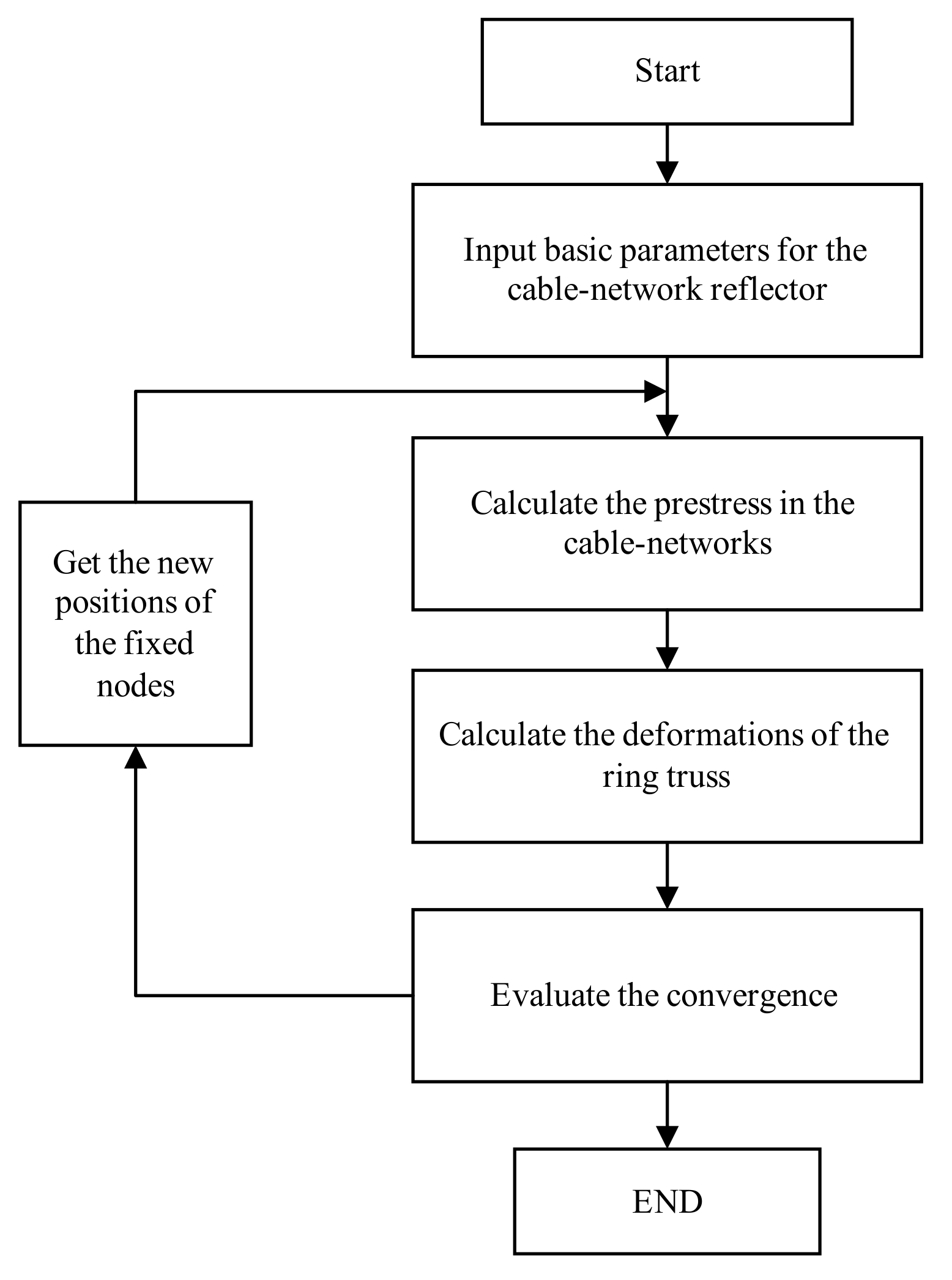
3. Form-Finding Method Considering the Deformation of Flexible Ring Truss

In most of the existing literature, the connecting points between the cable networks and flexible ring truss were assumed to be fixed during the form finding for the cable network reflector. Therefore, the deformations of the flexible ring truss due to tensions in the cable networks were not considered. In this section, a novel design method that considers the deformation of the ring truss is proposed. Since the ring truss is deformed, the coordinates of the fixed nodes are updated to achieve the objective shapes of the reflector. By modifying the coordinates of the fixed nodes, a new series of force density values are calculated to decrease the influence of the deformation on the accuracy of the reflector. The procedure of the design method is given below:
Step 1: Input basic parameters for the cable network reflector.
Step 2: A set of suitable force density values should be obtained, using the MATLAB program to design an objective shape of the cable network structure.
Step 3: Calculate the deformations of the ring truss in the ANSYS software to update the boundary coordinates. From Equation (12), the reaction force vector provided by the boundary nodes can be obtained as:
p x f = C f T Q C x + C f T Q C f x f p y f = C f T Q C y + C f T Q C f y f p z f = C f T Q C z + C f T Q C f z f
The deformations in the n th iteration step are obtained from the following equation:
Δ x f , n Δ y f , n Δ z f , n = K f p x f p y f p z f
Next, the coordinates of the fixed nodes are updated using:
x f , n y f , n z f , n = x f y f z f + Δ x f , n Δ y f , n Δ z f , n
Step 4: The surface root-sum-of-squares (RSS) error w n during the n th iteration is used as a performance metric of the obtained mesh reflector. The RSS error can be expressed as
w n = ( x n x 0 , n ) 2 + ( y n y 0 , n ) 2 + ( z n z 0 , n ) 2
The termination condition for the algorithm is specified as:
w n w n 1
where x 0 , n , y 0 , n , z 0 , n are the coordinates of the free nodes when the boundary nodes are fixed, and x n , y n , z n are the coordinates of the free nodes if the ring truss has a deformation in the n th iteration step.
Step 5: Generate the desired mesh shape with the obtained x 0 , n , y 0 , n , z 0 , n and x f , n , y f , n , z f , n .
The design flow is illustrated using the flowchart shown in Figure 8.

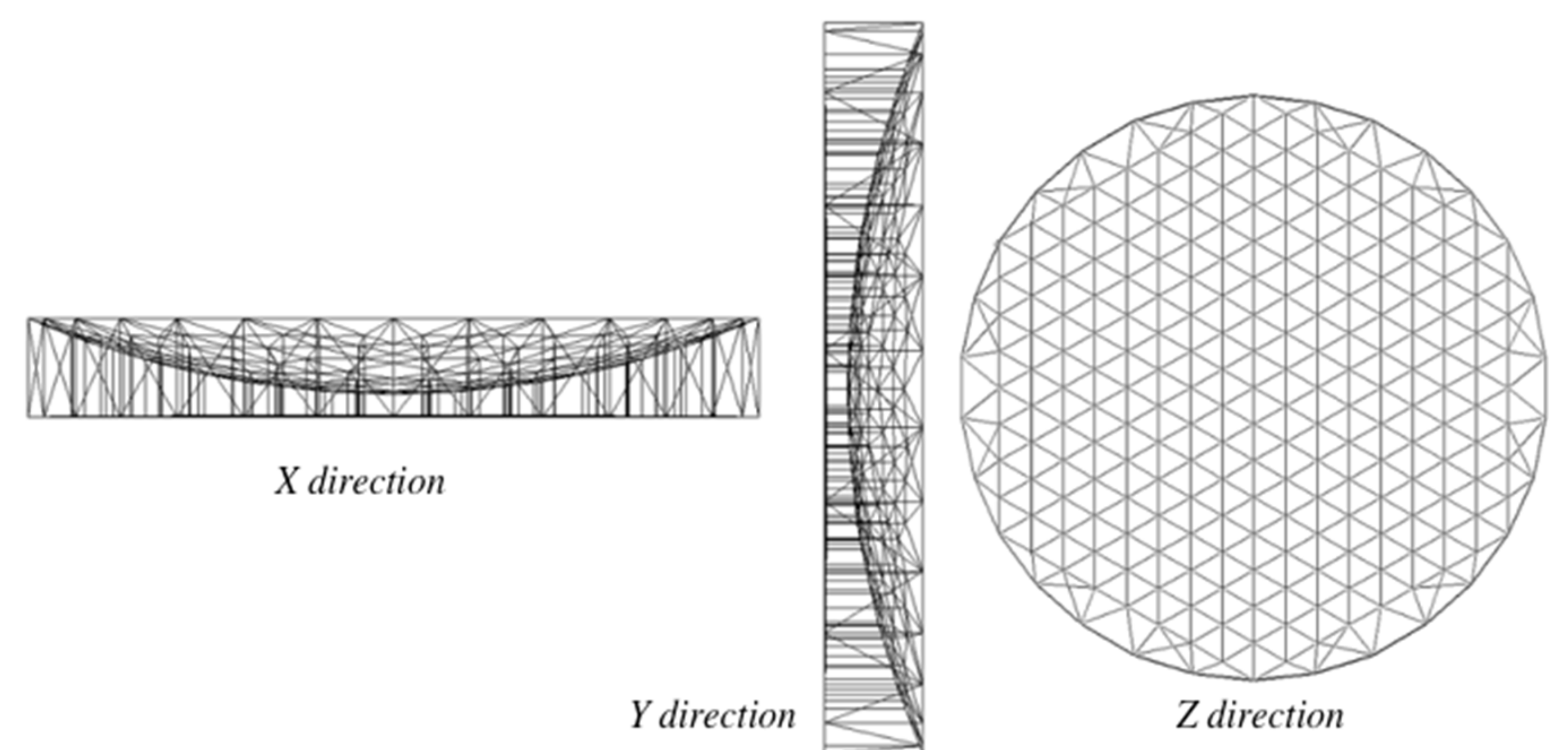
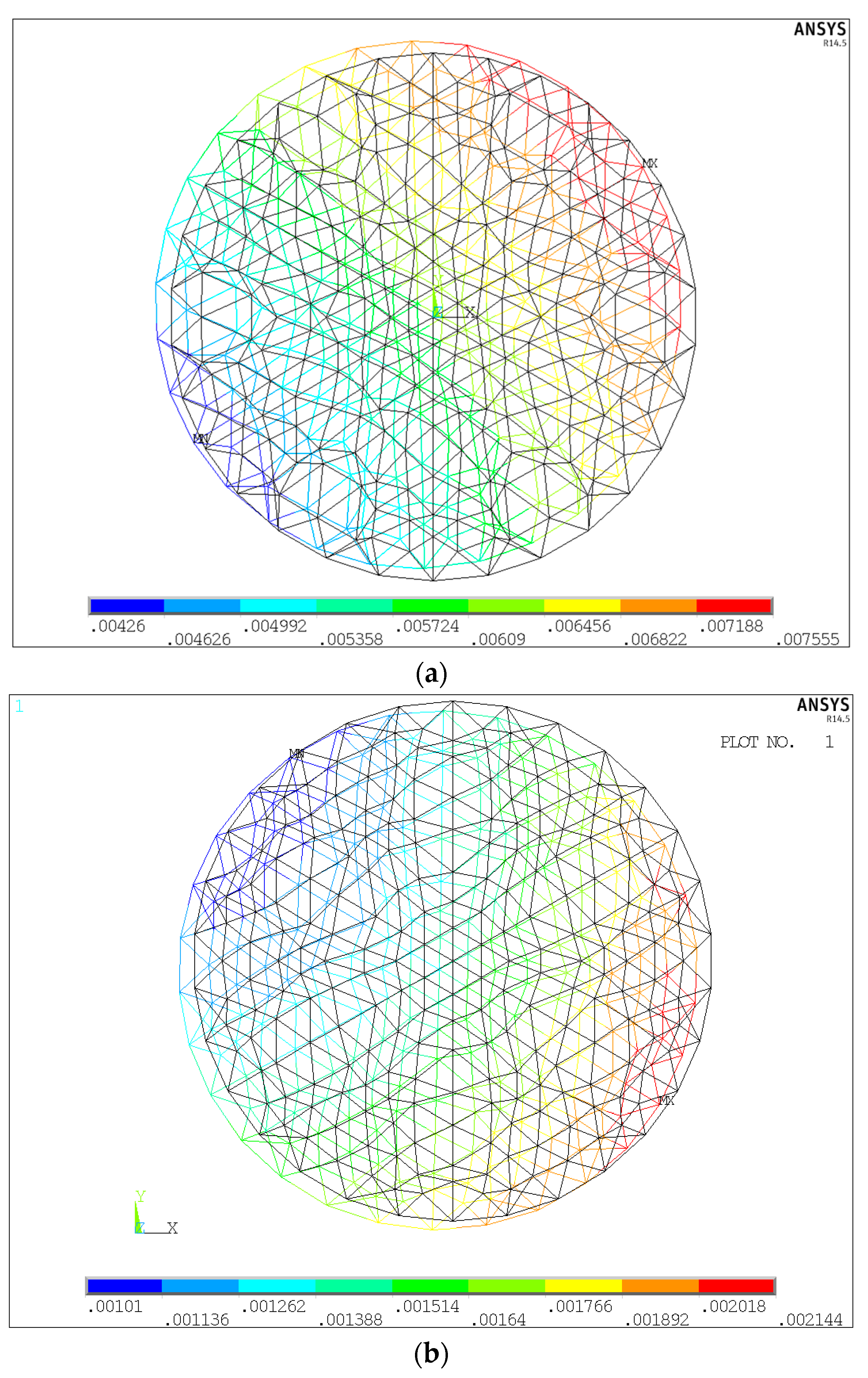
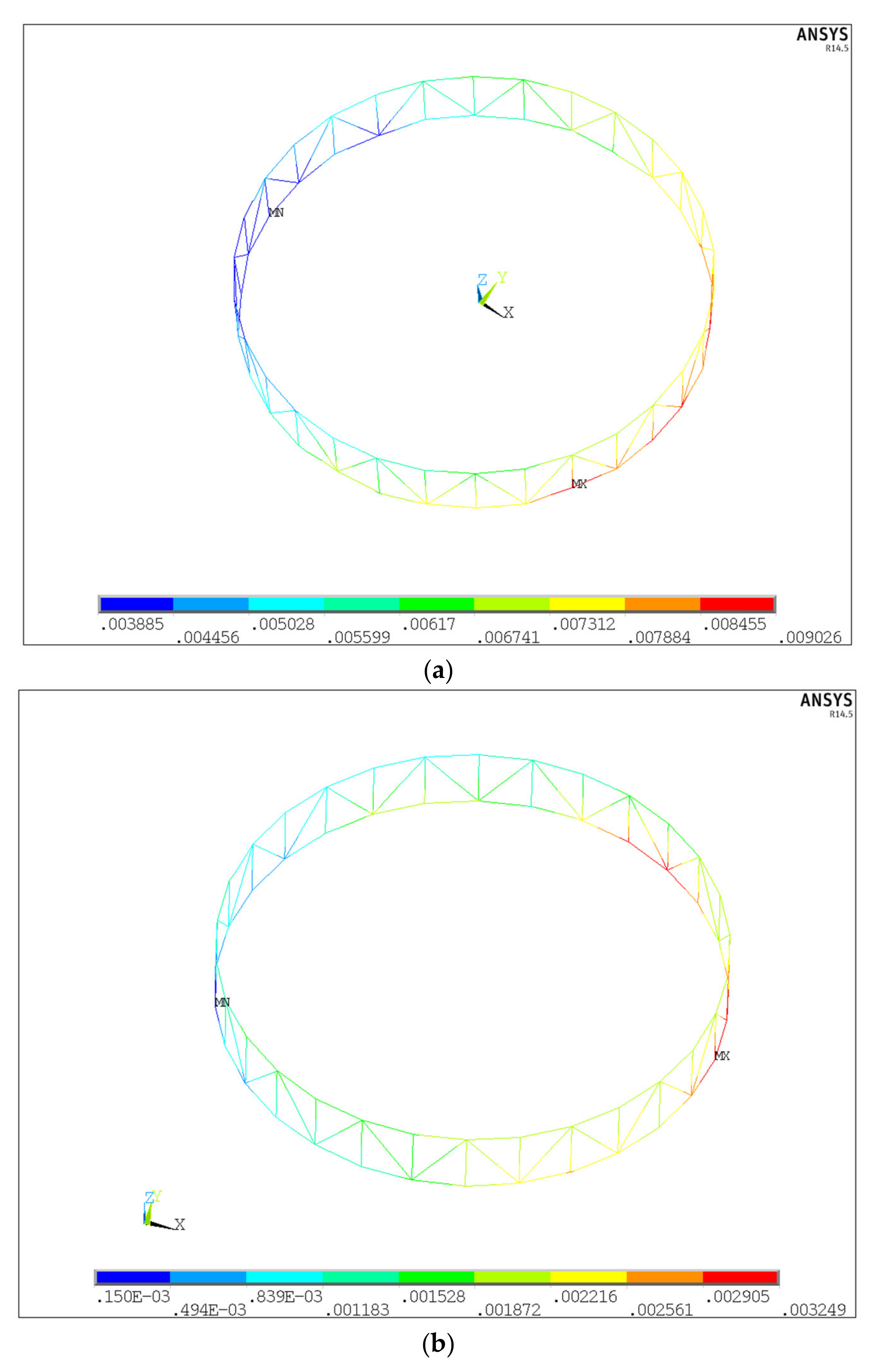
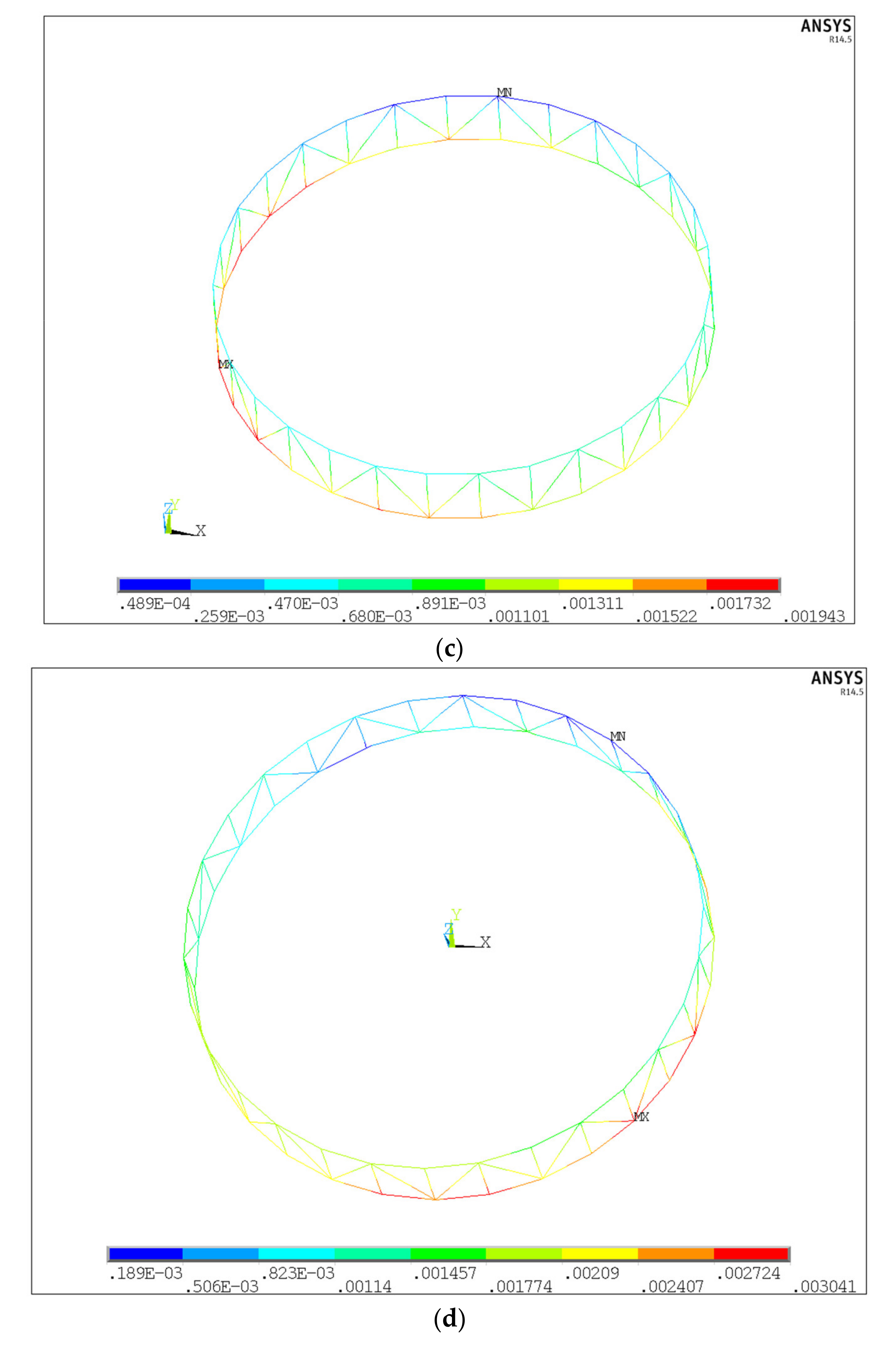
4. Numerical Simulations

In this section, to demonstrate the effectiveness of the proposed method, numerical examples for the design of an asymmetric cable network antenna are presented. A finite element model of the cable mesh antenna structure was built with the ANSYS software. Three views of the antenna structure are illustrated in Figure 9. The material parameters of the subject are given in Table 1 and the structural dimensions of the subject are as follows:
The diameter of the aperture: 16 m.
The focal length of the front reflector: 9.5 m.
The focal length of the rear reflector: 304.2 m.
Number of cable networks: 1555 (Front: 672, Rear: 672, Tie cables: 211).
Number of boundary cables: 120.
Number of free nodes: 422.
Number of connecting nodes: 60.
Type of facets: triangular facets.
Due to the complexity of the cable mesh antenna structure, we used APDL programming in ANSYS to build the model. The pre-stress which was obtained during the form-finding progress in MATLAB was applied to the cable nets in the form of pre-strain.
In order to compare the proposed approach and the conventional method without considering the flexibility of the supporting structure, the cable network antenna is designed using both methods. The results are shown in Figure 10 and Figure 11.
Figure 10 shows the contour nodal displacement of the front reflector which was calculated in ANSYS during successive iterations. From the figures, we can see that the maximum nodal displacement in the second iteration is the smallest, and that the nodal displacement increases in the third iteration. Hence, we set the second iteration as the termination iteration.
Figure 11 shows the contour nodal displacement of the supporting truss during successive iterations. From the figures, we can note that the deformation of the support truss decreases with successive iterations and the second iteration hass the smallest nodal displacement.
The differences between the free node positions of the objective shapes and that of the shapes at the equilibrium states are summarized in Table 2.
From Table 2, it can be observed that the free nodal position error for the conventional design approach is large as it does not consider the ring truss. Further, the result of the conventional method does not satisfy the surface accuracy requirement. In the case of the proposed method, with finite iterative steps, the tension distribution is uniform. Further, there is an obvious improvement in reflector accuracy. Compared with the conventional design method, the proposed design method achieves an accuracy improvement of 71.69% and 89.95% for the first and second iteration, respectively. We can also observe that the free nodal displacement error was increased in the third iteration, and hence the algorithm was stopped.

5. Conclusions

In this work, a design method for an asymmetric reflector is proposed. By using the FDM, a set of suitable tensions that were obtained using the MATLAB program language is searched using genetic algorithm for the desired asymmetric mesh configuration under fixed boundary nodes. Then, the displacements of the boundary nodes caused by the deformation of the flexible truss were calculated using the finite element method. Further, we updated the coordinates of the boundary nodes to eliminate the effect of the elastic deformations of the ring truss supporting structure on the surface accuracy, which will lead to a great improvement of the surface accuracy in the designed mesh shape. Finally, numerical simulations were conducted to verify the performance of the proposed approach. The simulation results demonstrated that the proposed approach could generate exact spatial parabolic mesh shapes that can satisfy the requirements. Therefore, the work presented in this paper can be used for the efficient designing of cable network structures.

Author Contributions

Conceptualization and methodology, Z.H. and Y.L.; software, Z.H.; validation, X.Z.; formal analysis, Z.H.; investigation, Z.H.; resources, Z.H.; data curation, Z.H.; writing—original draft preparation, Z.H.; writing—review and editing, Y.L. and X.Z. All authors have read and agreed to the published version of the manuscript.

Funding

This work is supported by the National Natural Science Foundation of China (Grant No. 11972024).

Institutional Review Board Statement

Not applicable.

Informed Consent Statement

Not applicable.

Data Availability Statement

Not applicable.

Conflicts of Interest

The authors declare no conflict of interest.

References

  1. Mileski, P.; Kornblith, J. Lightweight Deployable Antenna System. U.S. Patent 5,091,732, 25 February 1992. [Google Scholar]
  2. Takano, T.; Miura, K.; Natori, M.; Hanayama, E.; Inoue, T.; Noguchi, T.; Miyahara, N.; Nakaguro, H. Deployable antenna with 10-m maximum diameter for space use. IEEE Trans. Antennas Propag. 2004, 52, 2–11. [Google Scholar] [CrossRef]
  3. Salama, M.; Lou, M.; Fang, H. Deployment of inflatable space structures-a review of recent developments. In Proceedings of the 41st Structures, Structural Dynamics, and Materials Conference and Exhibit, Atlanta, GA, USA, 3–6 April 2000; p. 1730. [Google Scholar]
  4. Freeland, R.E.; Bilyeu, G.D.; Veal, G.R.; Steiner, M.D.; Carson, D.E. Large inflatable deployable antenna flight experiment results. Acta Astronaut. 1997, 41, 267–277. [Google Scholar] [CrossRef]
  5. Tabata, M.; Fujii, K.; Shintate, K.; Ozawa, S. Deployable antenna. U.S. Patent 20,120,193,498, 30 January 2012. [Google Scholar]
  6. Pellegrino, S. Deployable Structures; Springer: Berlin/Heidelberg, Germany, 2014; Volume 412. [Google Scholar]
  7. Thomson, M.W. The Astromesh deployable reflector. In Proceedings of the Antennas and Propagation Society International Symposium, Orlando, FL, USA, 11–16 July 1999; pp. 1516–1519. [Google Scholar]
  8. Tibert, A.G.; Pellegrino, S. Deployable tensegrity reflectors for small satellites. J. Spacecr. Rocket. 2002, 39, 701–709. [Google Scholar] [CrossRef] [Green Version]
  9. Tabarrok, B.; Qin, Z. Nonlinear-Analysis of Tension Structures. Comput. Struct. 1992, 45, 973–984. [Google Scholar] [CrossRef]
  10. Tang, Y.Q.; Li, T.J.; Ma, X.F. Form Finding of Cable Net Reflector Antennas Considering Creep and Recovery Behaviors. J. Spacecr. Rocket. 2016, 53, 610–618. [Google Scholar] [CrossRef]
  11. Tabata, M.; Yamamoto, K.; Inoue, T.; Noda, T.; Miura, K. Shape adjustment of a flexible space antenna reflector. J. Intell. Mater. Syst. Struct. 1992, 3, 646–658. [Google Scholar] [CrossRef]
  12. Fazli, N.; Abedian, A. Design of tensegrity structures for supporting deployable mesh antennas. Sci. Iran. 2011, 18, 1078–1087. [Google Scholar] [CrossRef] [Green Version]
  13. Mobrem, M. Methods of analyzing surface accuracy of large antenna structures due to manufacturing tolerances. In Proceedings of the 44th AIAA/ASME/ASCE/AHS/ASC Structures, Structural Dynamics, and Materials Conference, Norfolk, Virginia, 7–10 April 2003; p. 1453. [Google Scholar]
  14. Tanaka, H. Surface error estimation and correction of a space antenna based on antenna gainanalyses. Acta Astronaut. 2011, 68, 1062–1069. [Google Scholar] [CrossRef]
  15. Shi, H.; Yang, B.; Fang, H. Offset-feed surface mesh generation for design of space deployable mesh reflectors. In Proceedings of the 54th AIAA/ASME/ASCE/AHS/ASC Structures, Structural Dynamics, and Materials Conference, Boston, MA, USA, 8–11 April 2013; p. 1526. [Google Scholar]
  16. Meguro, A.; Harada, S.; Watanabe, M. Key technologies for high-accuracy large mesh antenna reflectors. Acta Astronaut. 2003, 53, 899–908. [Google Scholar] [CrossRef]
  17. Tang, Y.Q.; Li, T.J.; Ma, X.F. Pillow Distortion Analysis for a Space Mesh Reflector Antenna. AIAA J. 2017, 55, 3206–3213. [Google Scholar] [CrossRef]
  18. Wang, Z.; Li, T.; Deng, H. Form-finding analysis and active shape adjustment of cable net reflectors with PZT actuators. J. Aerosp. Eng. 2012, 27, 575–586. [Google Scholar] [CrossRef]
  19. Wang, Z.W.; Li, T.J.; Cao, Y.Y. Active shape adjustment of cable net structures with PZT actuators. Aerosp. Sci. Technol. 2013, 26, 160–168. [Google Scholar] [CrossRef]
  20. Yan, B.; Wang, K.; Kang, C.X.; Zhang, X.N.; Wu, C.Y. Self-Sensing Electromagnetic Transducer for Vibration Control of Space Antenna Reflector. IEEE/ASME Trans. Mechatron. 2017, 22, 1944–1951. [Google Scholar] [CrossRef]
  21. Xun, G.B.; Peng, H.J.; Wu, S.N.; Wu, Z.G. Active Shape Adjustment of Large Cable-Mesh Reflectors Using Novel Fast Model Predictive Control. J. Aerosp. Eng. 2018, 31, 04018038. [Google Scholar] [CrossRef]
  22. Tanaka, H.; Shimozono, N.; Natori, M.C. A design method for cable network structures considering the flexibility of supporting structures. Trans. Jpn. Soc. Aeronaut. Space Sci. 2008, 50, 267–273. [Google Scholar] [CrossRef] [Green Version]
  23. Maddio, P.D.; Meschini, A.; Sinatra, R.; Cammarata, A. An optimized form-finding method of an asymmetric large deployable reflector. Eng. Struct. 2019, 181, 27–34. [Google Scholar] [CrossRef]
  24. Li, T.; Zuowei, W.; Deng, H. Mesh reflector antennas: Form-finding analysis review. In Proceedings of the 54th AIAA/ASME/ASCE/AHS/ASC Structures, Structural Dynamics, and Materials Conference, Boston, MA, USA, 8–11 April 2013; p. 1576. [Google Scholar]
  25. Liu, W.; Li, D.X.; Yu, X.Z.; Jiang, J.P. Exact mesh shape design of large cable-network antenna reflectors with flexible ring truss supports. Acta Mech. Sin. 2014, 30, 198–205. [Google Scholar] [CrossRef]
  26. Li, T.J.; Jiang, J.; Deng, H.Q.; Lin, Z.C.; Wang, Z.W. Form-finding methods for deployable mesh reflector antennas. Chin. J. Aeronaut. 2013, 26, 1276–1282. [Google Scholar] [CrossRef] [Green Version]
  27. Tran, H.C.; Lee, J. Self-stress design of tensegrity grid structures with exostresses. Int. J. Solids Struct. 2010, 47, 2660–2671. [Google Scholar] [CrossRef] [Green Version]
  28. Linkwitz, K.; Schek, H.-J. Einige bemerkungen zur berechnung von vorgespannten seilnetzkonstruktionen [Some comments on the calculation of pre-tensioned cable network constructions]. Ing. Arch. 1971, 40, 145–158. (In German) [Google Scholar] [CrossRef]
  29. Davis, L. Handbook of Genetic Algorithms; Van Nostrand Reinhold: New York, NY, USA, 1991. [Google Scholar]
  30. Michalewicz, Z. Evolution strategies and other methods. In Genetic Algorithms+ Data Structures = Evolution Programs; Springer: Berlin/Heidelberg, Germany, 1996; pp. 159–177. [Google Scholar]
  31. Goldberg, D.E.; Holland, J.H. Genetic algorithms and machine learning. Mach. Learn. 1988, 3, 95–99. [Google Scholar] [CrossRef]
  32. Ribeiro Filho, J.L.; Treleaven, P.C.; Alippi, C. Genetic-algorithm programming environments. Computer 1994, 27, 28–43. [Google Scholar] [CrossRef]
Figure 1. An illustration of the AstroMesh concept.
Applsci 12 04508 g001
Figure 2. Identical paraboloid-shaped net model.
Applsci 12 04508 g002
Figure 3. Asymmetric paraboloid-shaped net model.
Applsci 12 04508 g003
Figure 4. A two-dimensional cable net.
Applsci 12 04508 g004
Figure 5. The finite element model for the antenna reflector.
Applsci 12 04508 g005
Figure 6. The unique cable nets.
Applsci 12 04508 g006
Figure 7. An element of a cable net structure.
Applsci 12 04508 g007
Figure 8. Flowchart of the proposed method using an iterative technique.
Applsci 12 04508 g008
Figure 9. Three views of the antenna structure.
Applsci 12 04508 g009
Figure 10. The contour nodal displacement solution of the front reflector: (a) the initial iteration, (b) the first iteration, (c) the second iteration, and (d) the third iteration.
Applsci 12 04508 g010aApplsci 12 04508 g010b
Figure 11. The contour nodal displacement solution of the supporting truss: (a) the initial iteration, (b) the first iteration, (c) the second iteration, and (d) the third iteration.
Applsci 12 04508 g011aApplsci 12 04508 g011b
Table 1. Material parameters of the structure.
Material ParameterMaterial PropertiesElastic Modulus (GPa) Density   ( k g / m 3 ) Diameter (m)
Cable networkKevlar49137.0714400.002
Ring trussCarbon Fiber 60J5881940innerouter
0.0180.02
Table 2. Comparison of the design results using the proposed and the conventional method.
The Initial Reflector DataPresent Approach
1st Iteration2nd Iteration3rd Iteration
Max–min distributed tension in the front reflector (N)17.06/3.5327.39/6.4022.24/5.7027.90/5.00
Max–min tension ratio of cable net4.824.283.905.58
Free nodal position error (m)7.56 × 10−32.14 × 10−30.76 × 10−31.95 × 10−3
Improvement of surface accuracy71.69%89.95%74.21%
Publisher’s Note: MDPI stays neutral with regard to jurisdictional claims in published maps and institutional affiliations.

