Article

Study on the Interference Distribution Characteristics of the HVDC Grounding Electrode Current with Buried Pipelines Based on MoM and FEM

1
State Key Laboratory of Alternate Electrical Power System with Renewable Energy Sources, North China Electric Power University, Beijing 102206, China
2
China Electric Power Research Institute, Beijing 100192, China
*
Author to whom correspondence should be addressed.
Appl. Sci. 2022, 12(9), 4433; https://doi.org/10.3390/app12094433
Submission received: 4 April 2022 / Revised: 21 April 2022 / Accepted: 25 April 2022 / Published: 27 April 2022

Abstract

:
It is very important to calculate the interference of high voltage direct current (HVDC) grounding current with pipelines accurately and take proper protective measures to ensure energy transmission safety. There is still a lack of systematic research into related prediction methods that consider the nonlinear polarization on the interface between the soil and pipelines. In this paper, a methodology is proposed for calculating the coupling voltage and current on buried pipelines induced by grounding currents that accounts for nonlinear polarization based on the method of moments (MoM) and the finite element method (FEM). The validity of the proposed mathematical model is verified by a scale experiment. The interference distribution characteristics under different parameters are analyzed using the proposed method. The results show that the relationship between the maximum leakage current density and the electrode grounding current satisfy the linear function. The corrosion area becomes more concentrated as the grounding current increases. The corrosion area range increases substantially as the distance increases, whereas the influence degree decreases substantially. Both the maximum leakage current density and corrosion risk area are positively correlated with the soil resistivity.

1. Introduction

High voltage direct current (HVDC) transmission technology has been widely used in the power system for its advantages in large transmission capacity and long transmission distance. The grounding electrode current can reach several kilo-amperes when the HVDC transmission project is under monopole operation [1]. This current may cause severe interference with buried pipelines in the vicinity of the electrode [2,3,4]. The currents can flow into the pipeline at one point and flow out at another point. Metal corrosion can occur at the current-in point, while hydrogen embrittlement may occur at the current-out point, which both threaten the operation safety of pipeline engineering [5,6]. Therefore, it is very important to determine the interference characteristics of the electrode current with buried pipelines for pipeline risk assessment and safety protection.
In pipeline engineering, pipe-to-soil potential (PSP) and leakage current density are often used to indicate the DC interference degree [7]. In the past, numerous tests were needed to obtain these two indicators along the pipelines [8,9]. In situ measurement is often costly and time-consuming so simulations represent an interesting option for the study of such phenomena. Many calculation methods have been proposed to determine the interference under different conditions. Lagace et al. used the transmission line model to simulate long pipelines by applying the pipeline conductor parameters and coating parameters to the transmission line equations [10]. Yu et al. extended the simulation methodology by adding a local damage equivalent branch and cathodic protection branch for more practical engineering applications [11]. Giao et al. first calculated the current distribution of the HVDC grounding electrode by the method of moments (MoM) [12]. Then Dawalibi et al. developed the multi-step method to calculate the interaction of the multi-electrodes based on MoM [13,14]. Zhang et al. proposed a field-circuit coupling model to consider the impacts of different protective measures [15]. However, the above-mentioned numerical methods cannot consider the nonlinear electrochemical polarization effectively, which may lead to inaccurate results for density and PSP calculations [16]. The PSP deviates from the equilibrium potential when polarization occurs. This deviation becomes greater as the leakage current density increases. Besides, the polarization relationship is nonlinear and it can result in improper protective measures for pipeline safety.
There are many parameters that can influence the calculation results, such as the electrode grounding current, soil resistivity, soil structures, pipeline coating characteristics, and the distance between the electrode and pipeline. Differences in these parameters can lead to different pipeline safety assessments and protective measures. Therefore, it is necessary to study the interference distribution characteristics under the various above-mentioned parameters.
In this paper, a methodology based on a combination of MoM and FEM is proposed to calculate the pipeline interference caused by HVDC electrode current. The proposed method takes into account the pipe-soil interface polarization by introducing a nonlinear boundary condition which is difficult to consider for traditional methods. Then the interference distribution characteristics under different parameters are studied using the proposed method. These characteristics can be used to develop guidelines for practical engineering.

2. Interference Mechanism of the Grounding Current

The high-voltage DC grounding electrode is a grounding facility that provides a low resistance path during the operation of the HVDC transmission system [17]. 
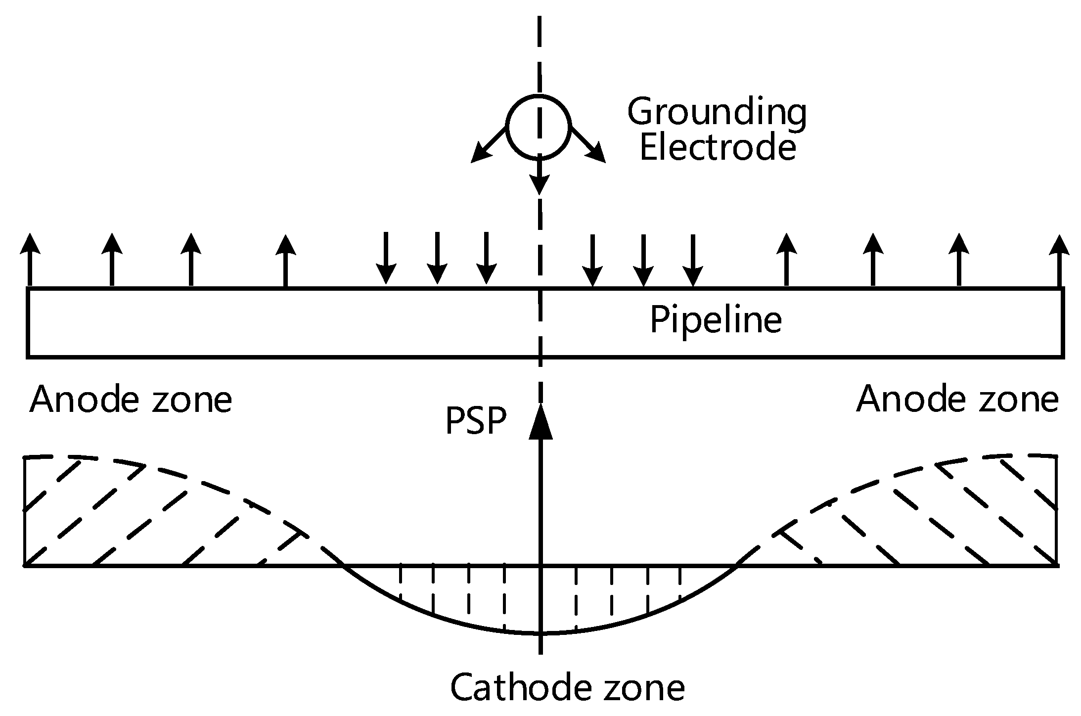
Figure 1 shows the interference process of the DC grounding electrode current on the buried metallic pipelines. The earth currents flow into the pipeline in the area close to the grounding electrode when the electrode is under anode operation. The currents flow out of the pipeline at the two ends which are far away from the electrode. As we can see, electrochemical corrosion occurs in the area currents flow out. The pipe-soil potential also has an obvious positive shift.
Different electrochemical reactions occur for different interference areas [18]. The electrochemical reaction for the anode interference area is usually described by:
2 F e 2 F e 2 + + 4 e
For the cathode interference area, hydrogen evolution reaction or oxygen absorption reactions dominate under different soil medium environments. In general, it can be shown as follows:
2 H + + 2 e H 2 acid   oxygen - free   condition H 2 O + 2 e 2 OH + H 2 neutral   or   alkaline   oxygen - free   condition   O 2 + 4 H + + 4 e 2 H 2 O acid   aerobic   condition O 2 + 2 H 2 O + 4 e 4 OH alkaline   aerobic   condition
The above electrochemical reactions can finally lead to a specific relationship between the PSP and the leakage current which can be defined as follows:
J = f p ( φ p φ s )
where J, φp and φs are the leakage current density, the pipe-side potential and the soil-side potential interface between the soil and pipe, respectively. The nonlinear function fp, which describes the relationship between the pipe-to-soil potential and the leakage current density, can be measured by experiment. The three-electrode system is often used to measure the polarization curves with the potential sweep method [19]. Figure 2 shows the typical three-electrode system for measuring polarization curves.
The discrete measurement data can be fitted by the Butler-Volmer equation which is one of the most fundamental equations in electrochemical kinetics. Equation (2) shows the typical Butler-Volmer equation [20]:
J = f P ( E ) = J c o r r ( exp ( E E c o r r β a ) exp ( E E c o r r β c ) )
where J and E are current density and PSP, respectively, and are obtained by measurement. E corr , J corr , β a , β c are the metal self-corrosion potential, self-corrosion current density, Tafel slope of the anode reaction and Tafel slope of the cathode reaction, respectively. The four parameters to be fitted can be obtained using the least square method. Then, the fitted functions can be used in the proposed methodology. The methodology must consider the nonlinear polarization to calculate the current and potential distribution accurately.

3. Mathematical Model Combining MoM with FEM

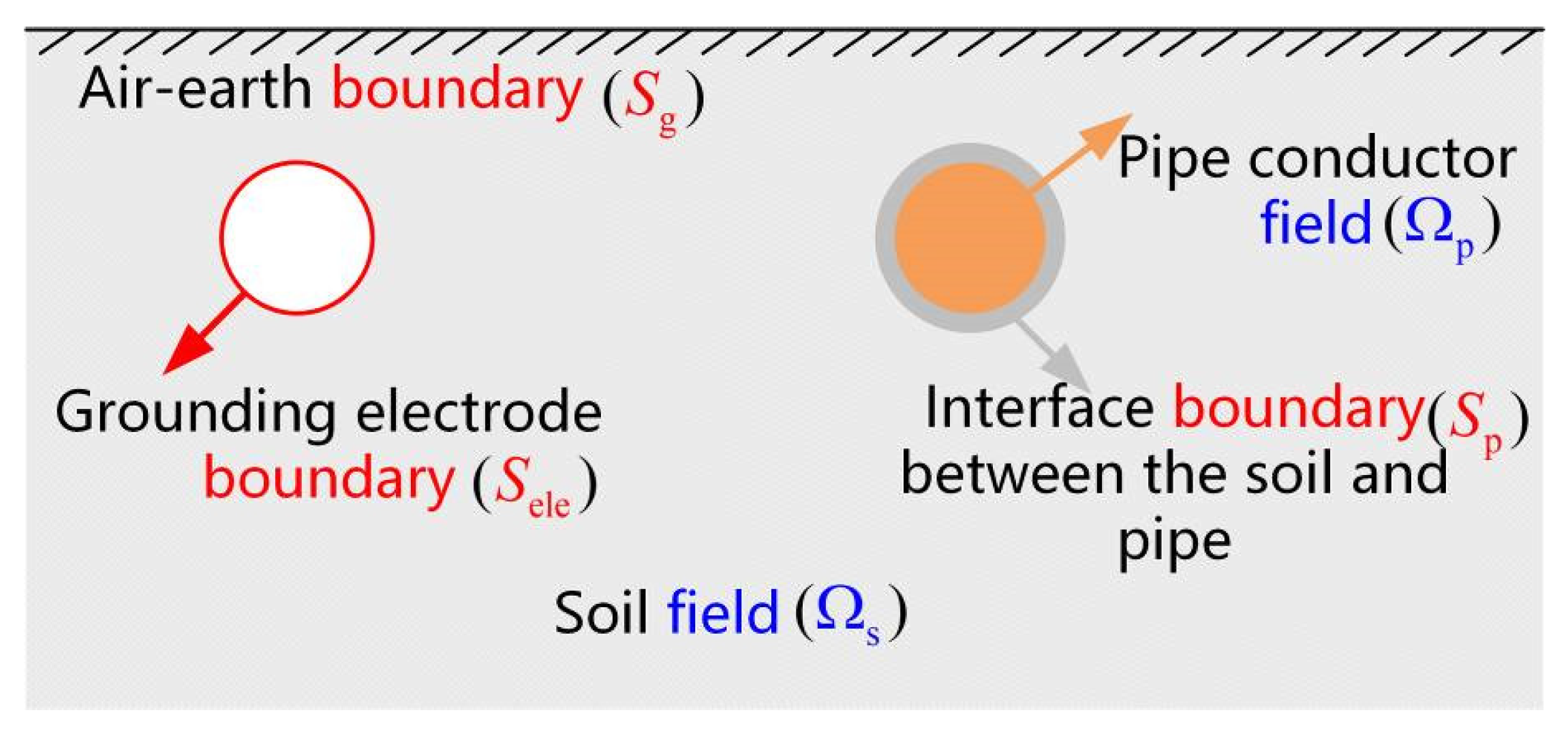
Pipeline corrosion is mainly caused by the resistive coupling of the grounding currents on the pipeline metal. The computation domain includes the soil area, the pipeline conductor area, as well as the infinite air-earth boundary, the grounding conductor boundary, and the interface boundary between the soil area and the pipeline conductor area. Figure 3 shows the boundary value problem of the resistive coupling model between the grounding electrode and pipelines.
The conductivities are assumed to be homogeneous. Then, the soil field Ωs and pipe conductor field Ωp belong to the constant current field so the potential satisfies Laplace’s equations. The air can be considered as electrical insulating medium so the current flowing out of the air-earth boundary (Sg) is zero. The total leakage current of the grounding electrode should equal the injected current in the HVDC transmission system based on the charge conservation law. According to the interface conditions for electric field vectors, the current density on the soil side should equal the current density on the pipe conductor side. Besides, the leakage current density also should satisfy the polarization relationship with the pipe-to-soil potential ( φ s φ p ). The theoretical equations for the above three-dimensional boundary value problem can be formulated as follows:
2 φ s ( r ) = 0 , r Ω s 2 φ p ( r ) = 0 , r Ω p φ s ( r ) n = 0 , r S g S ele σ s φ s ( r ) n d s = I hvdc , r S ele σ p φ p ( r ) n = σ s φ s ( r ) n = f p ( φ p ( r ) φ s ( r ) ) , r S p
where r is an arbitrary coordinate in the computation domain, Ihvdc is the grounding current of the HVDC grounding electrode, and σ p and σ s are the conductivity of the pipe conductor and soil medium, respectively. A numerical method combining MoM and FEM is proposed to solve the above equations. The Laplace equation in the soil area is discretized by MoM which is suitable for open-domain problems. The Laplace equation in pipe conductor area is discretized by FEM which is suitable for enclosure domain problems. By applying the nonlinear polarization boundary conditions between the two areas, the two methods can be coupled for solving.
The potential of an arbitrary point in the soil area can be expressed as follows:
φ s ( r ) = s G ( r , r ) J leak ( r ) d s ,   s S ele , S p
where r is the current source coordinate in the soil area, J leak ( r ) is the leakage current density for the buried conductor, and G ( r , r ) is the Green’s function for the above boundary problem. The electrode conductor and pipe conductor are divided into M and N segments, respectively. The basis function for different segment current density can be expressed as follows:
v i = 1 r Δ i 0 r Δ i
where Δ i is the definitional domain of the buried conductors so J leak ( r ) can be expressed as follows:
J leak ( r ) = i = 1 M + N c i v i
c 1 , c 2 , c M are the current density of the electrode conductor segments. c M + 1 , c M + 2 c M + N are the current density of the pipe conductor segments. Based on the MoM and point match method the following algebraic equation set can be formed.
G ( r 1 , 1 ) G ( r 1 , M ) G ( r 1 , M + 1 ) G ( r 1 , M + N ) G ( r M , 1 ) G ( r M , M ) G ( r M , M + 1 ) G ( r M , M + N ) G ( r M + 1 , 1 ) G ( r M + 1 , M ) G ( r M + 1 , M + 1 ) G ( r M + 1 , M + N ) G ( r M + N , 1 ) G ( r M + N , M ) G ( r M + N , M + 1 ) G ( r M + N , M + N ) c 1 c M c M + 1 c M + N = φ ( e , 0 ) φ ( e , 0 ) φ ( s , 1 ) φ ( s , N )
The electrode is considered as an equipotential φ ( e , 0 ) . The pipe potential on the soil side is φ ( s , 1 ) , φ ( s , 2 ) , φ ( s , N ) .
Using the finite element Galerkin method for the pipe conductor area, another equation set can be formed as follows:
K 1 , 1 K 1 , N K 1 , N + 1 K 1 , N + P K N , 1 K N , N K N , N + 1 K N , N + P K N + 1 , 1 K N + 1 , 1 K N + 1 , N + 1 K N + 1 , N + P K N + P , 1 K N + P , N K N + P , N + 1 K N + P , N + P φ ( p , 1 ) φ ( p , N ) φ ( p , N + 1 ) φ ( p , N + P ) = F ( φ ( p , 1 ) φ ( s , 1 ) ) F ( φ ( p , N ) φ ( s , N ) ) 0 0
K is the Stiffness matrix element for different nodes. φ ( p , 1 ) , φ ( p , 2 ) , φ ( p , N ) are the pipe potential on the pipe side. φ ( p , N + 1 ) , φ ( p , N + 2 ) , φ ( p , N + P ) are the non-boundary node potentialin the pipe conductor area. F ( φ ( p , i ) φ ( s , i ) ) , i = 1 , 2 , N are the load elements which depend on the nonlinear polarization function. According to charge conservation, the electrode segment currents obey the following equation:
i = 1 M c i Δ s i = I hvdc
By combining Equations (7)–(9), the distribution of the PSP and leakage current along the pipeline can be solved with the Newton–Raphson Method.

4. Experimental Verification

4.1. Experiment System

To verify the effectiveness of the proposed methodology, a scale problem experiment was conducted. Figure 4 shows the experiment system layout for the scale grounding electrode and pipeline.
The scale electrode was a 30 m diameter steel circle buried at a depth of 1.5 m. The pipeline was buried 28 m away from the electrode at a depth of 1 m. The grounding current was supplied by a current generator with 300 A maximum output current. The pipe material was X80 steel. The soil was considered as a homogeneous medium and the soil resistivity is r, pH = 8. The leakage current density and PSP along the pipeline were measured with the test coupons. The test points layout is shown in Figure 5.
For each test point, the test circuit is shown in Figure 6. based on the external coupon method [21].
Figure 7 shows the polarization relationship for the above-mentioned soil and pipe material. The current density is plotted with logarithmic coordinates for a better view. “log J” means the common logarithm of the leakage current density.

4.2. Verification of Calculation Method with Expriments Results

The buried conductors was subdivided into about 3000 segments. Boundary conditions were considered in the Green’s function when applying MoM. The pipeline conductor domain was subdivided into 45,800 tetrahedron elements. The nonlinear polarization conditions can be treated as a Neumann boundary in each iterative computation when applying FEM. The leakage current density and PSP were measured under 100 A and 150 A grounding current, respectively. The results of the experiment and calculation are shown in Figure 8.
The results show that, the current density and PSP at the center point are the largest along the pipeline for both test results and calculation results. The maximum test leakage current density changed from 5.987 mA/cm2 to 8.719 mA/cm2 when the grounding current changed from 100 A to 150 A. Accordingly, the maximum calculated leakage current density changed from 5.667 mA/cm2 to 8.604 mA/cm2. The relative error between the calculated results and the measured results for leakage current is 1.32–5.35%. In the same way, the relative error for PSP can be obtained, that is 2.63–7.72%. As the grounding current increases, the relative error becomes smaller. Therefore, the validity of the calculation method is verified by experiment results.

5. Interference Distribution Characteristics

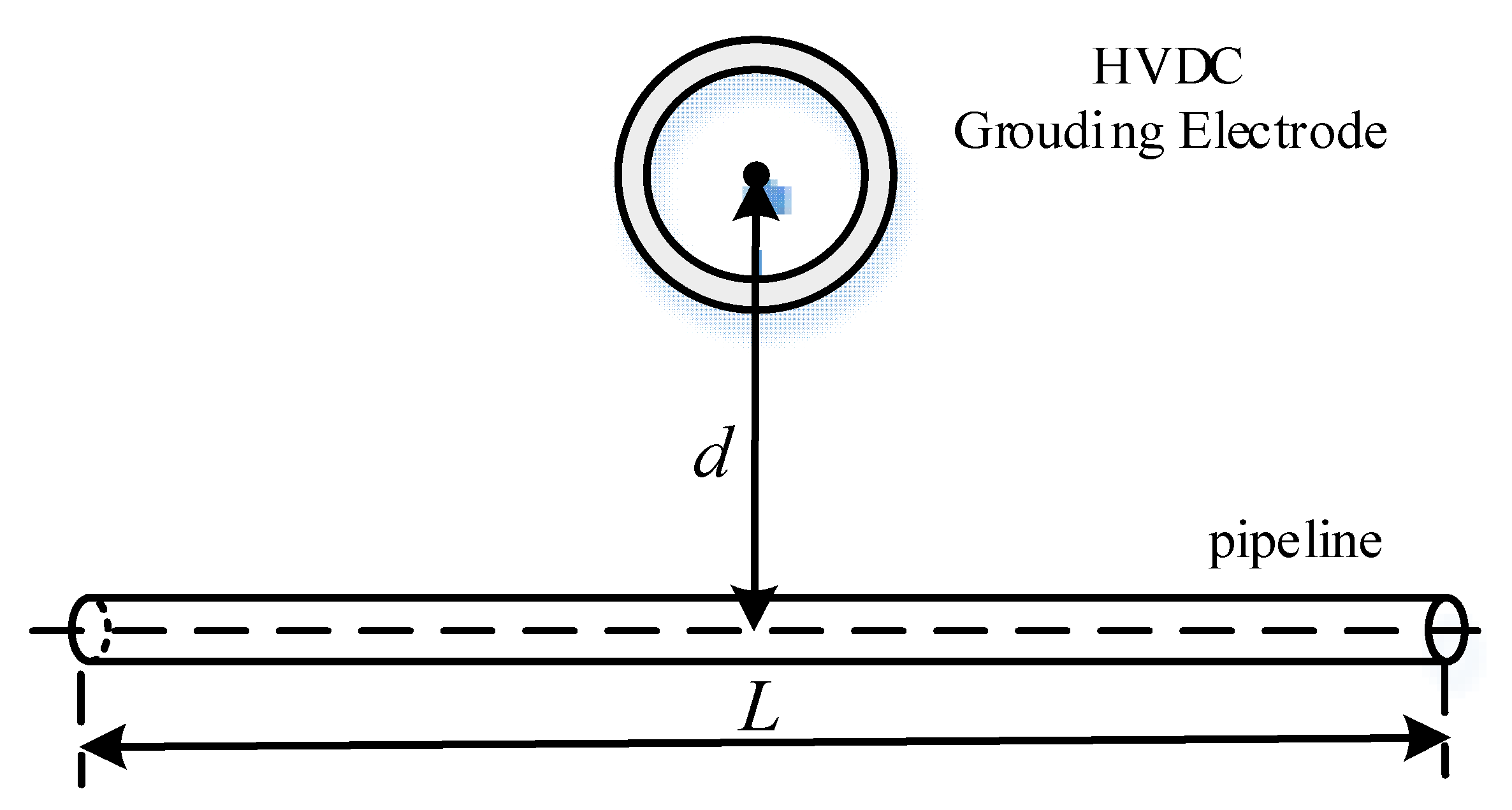
Based on the proposed calculation model, the interference distribution characteristics were analyzed under different parameters. These parameters include the electrode currents, soil resistivity, and the distance between the electrode and pipelines. Considering the following typical interference model, the length of the pipeline is L, and the distance between the electrode and pipeline is d. The soil is considered as a homogeneous medium and the soil resistivity is r, pH = 8. The pipe material was X80 steel. A schematic diagram of the pipeline and HVDC grounding electrode arrangement is shown in Figure 9.

5.1. Electrode Current

The relationship between the polarization potential and current density is the same as in Section 5.1 and shown in Figure 7. The other parameters are listed in Table 1.
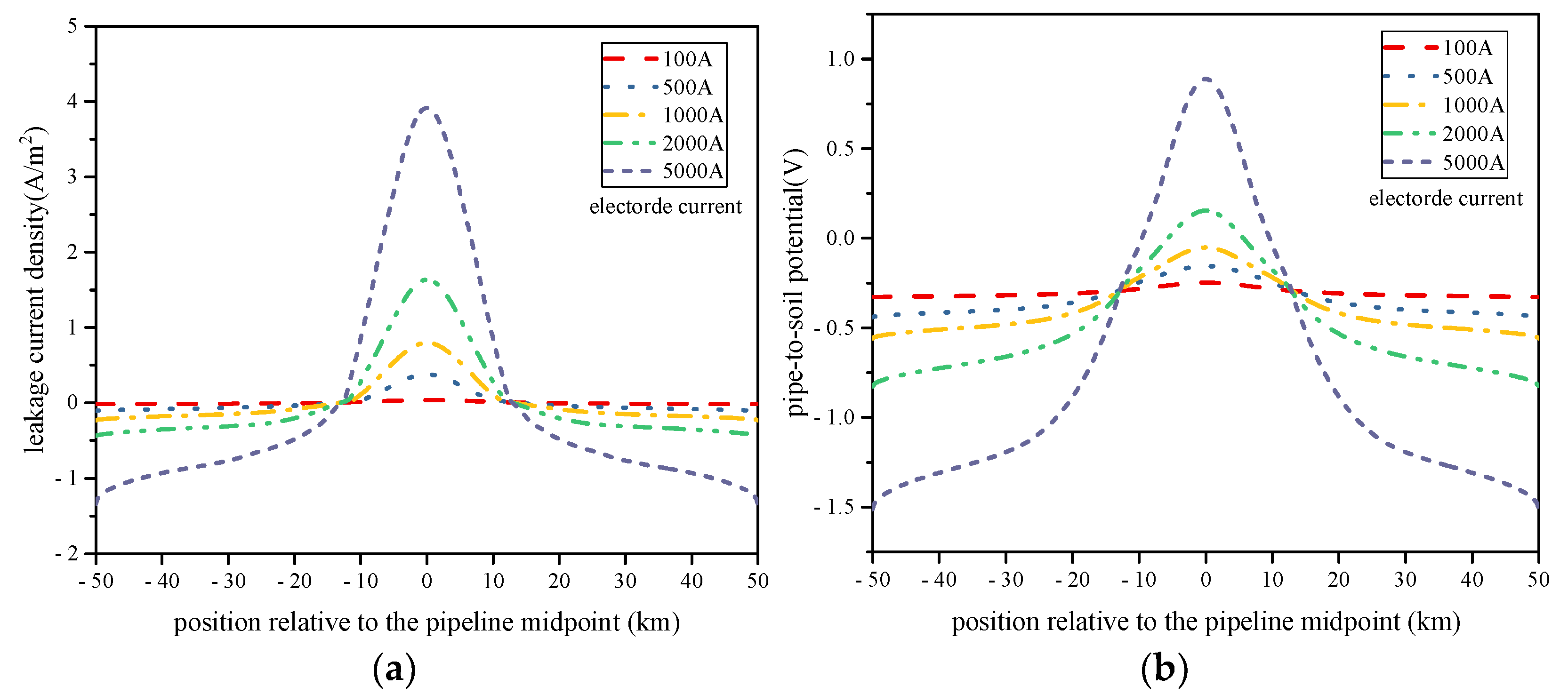
The distribution of the leakage current density and pip-to-soil potential under different HVDC ground currents are shown in Figure 10.
As can be seen in Figure 10, the leakage current density and PSP reach 3.92 A/m2 and 0.89 V, respectively, when the grounding current is 5000 A. Both maximum leakage current density and maximum PSP increase as the electrode grounding current increases. Regression analysis shows that the relationship between the maximum leakage current density Jmax and the electrode grounding current Ihvdc is linear, that is Jmax = a1·Ihvdc + b1 where a1 and b1 are fitting constant coefficients.
The maximum value is located at the midpoint of the pipeline. When currents flow out of the pipe, the pipeline faces corrosion risk, especially for the central area of the pipeline. 
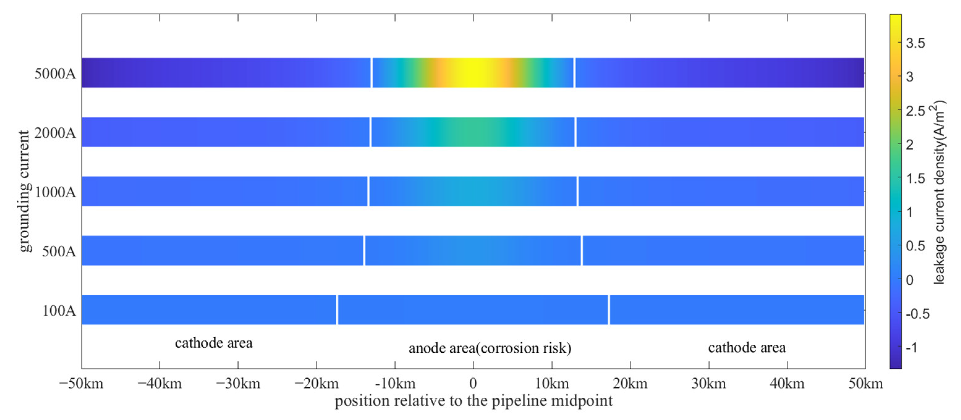
Figure 11 shows the corrosion risk area distribution under different grounding currents.
The length of anode area is 34.5 km under 100 A, whereas the length of anode area is 25.7 km under a 5000 A grounding current The result shows that the length facing corrosion risk decreases as the HVDC grounding current increases, which means the corrosion area is becoming more concentrated. The effect of grounding current on the anode area range is not very significant when the current exceeds 1000 A.

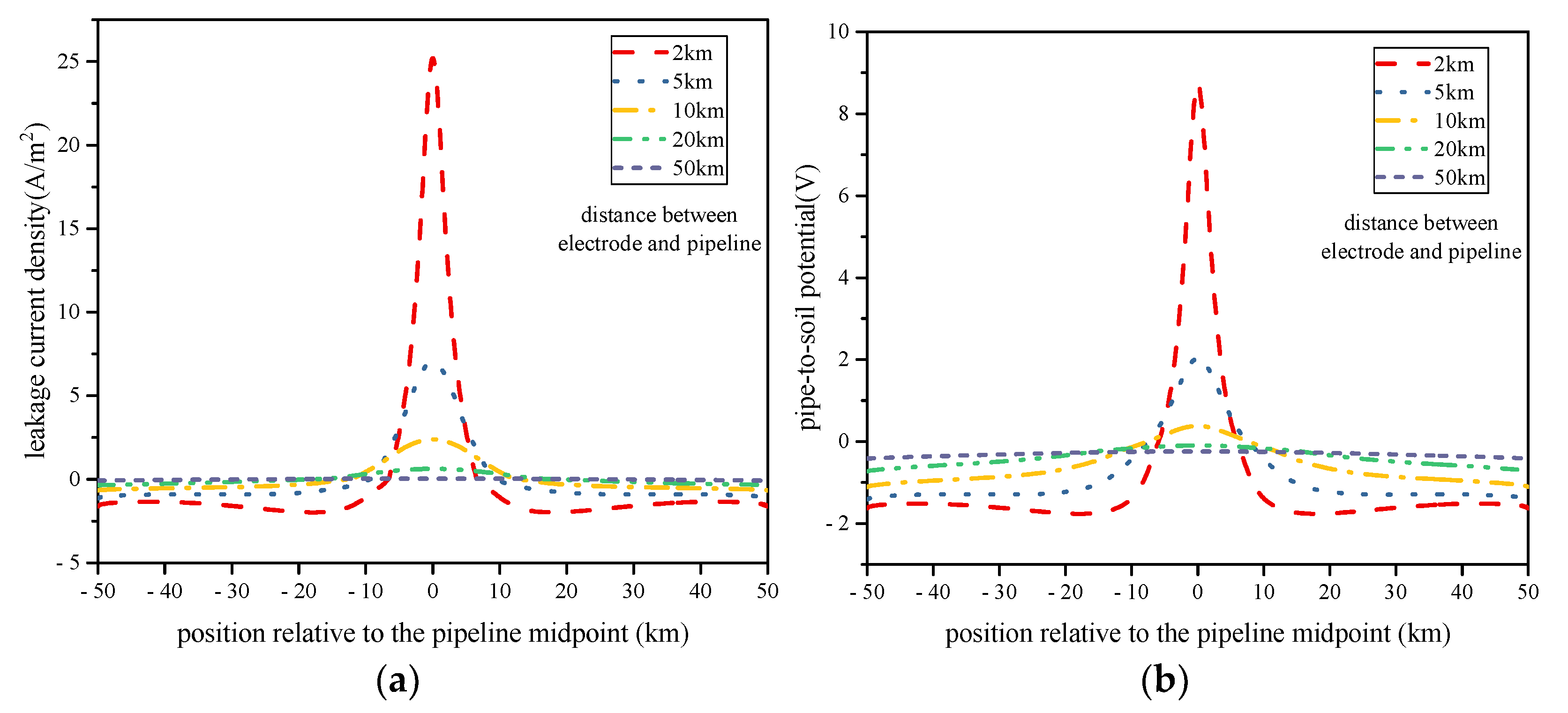
5.2. Distance between Electrode and Pipelines

The interference scope of the HVDC grounding current can reach tens of kilometers. Therefore, the potential and density distribution characteristics were studied in the range from 2 km to 50 km. A schematic diagram for the pipeline and HVDC grounding electrode arrangement is shown in Figure 9. Five distance types (2 km, 5 km, 10 km, 20 km, 50 km) were chosen for study. The HVDC grounding current is 3000 A. The other parameters are the same as those listed in Table 1. The relationship between polarization potential and current density is the same as in Section 5.1 and shown in Figure 7.
The results are shown in Figure 12 for different distances between the electrode and pipelines.
The maximum leakage current density and PSP reach 25.2 A/m2 and 8.74 V, respectively, when the distance between electrode and pipeline is 2 km. As the distance increases, the maximum current density and PSP decrease gradually. Regression analysis shows that the relationship between the maximum leakage current density Jmax and the distance d satisfy negative exponential function, that is J max = a 2 d b 2 (b2 < 0) where a2 and b2 are fitting constant coefficients. That means that the interference current density increases as power function when the distance between electrode and pipeline decreases.
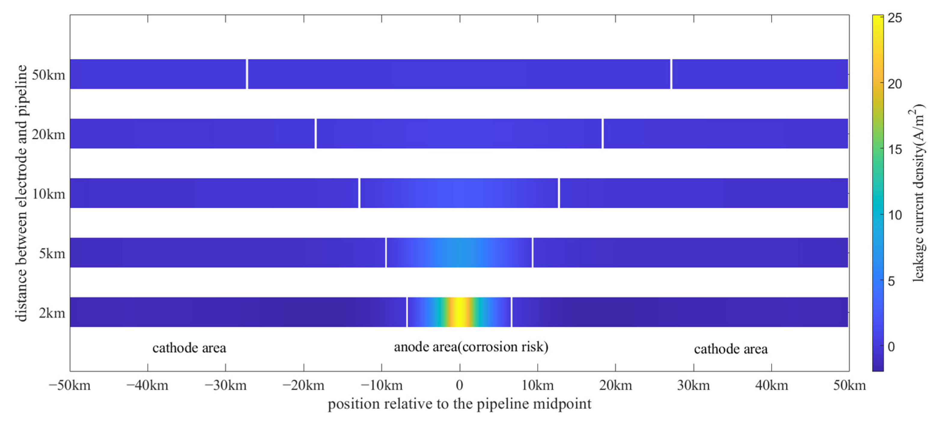
Figure 13 shows the interference range for the anode area and cathode area along the pipeline for different distances between the electrode and pipeline.
The distance between the electrode and pipeline has a significant influence on the anode area range. The anode area range increases as the distance increases. Although the anode area range extends, the influence degree decreases substantially.

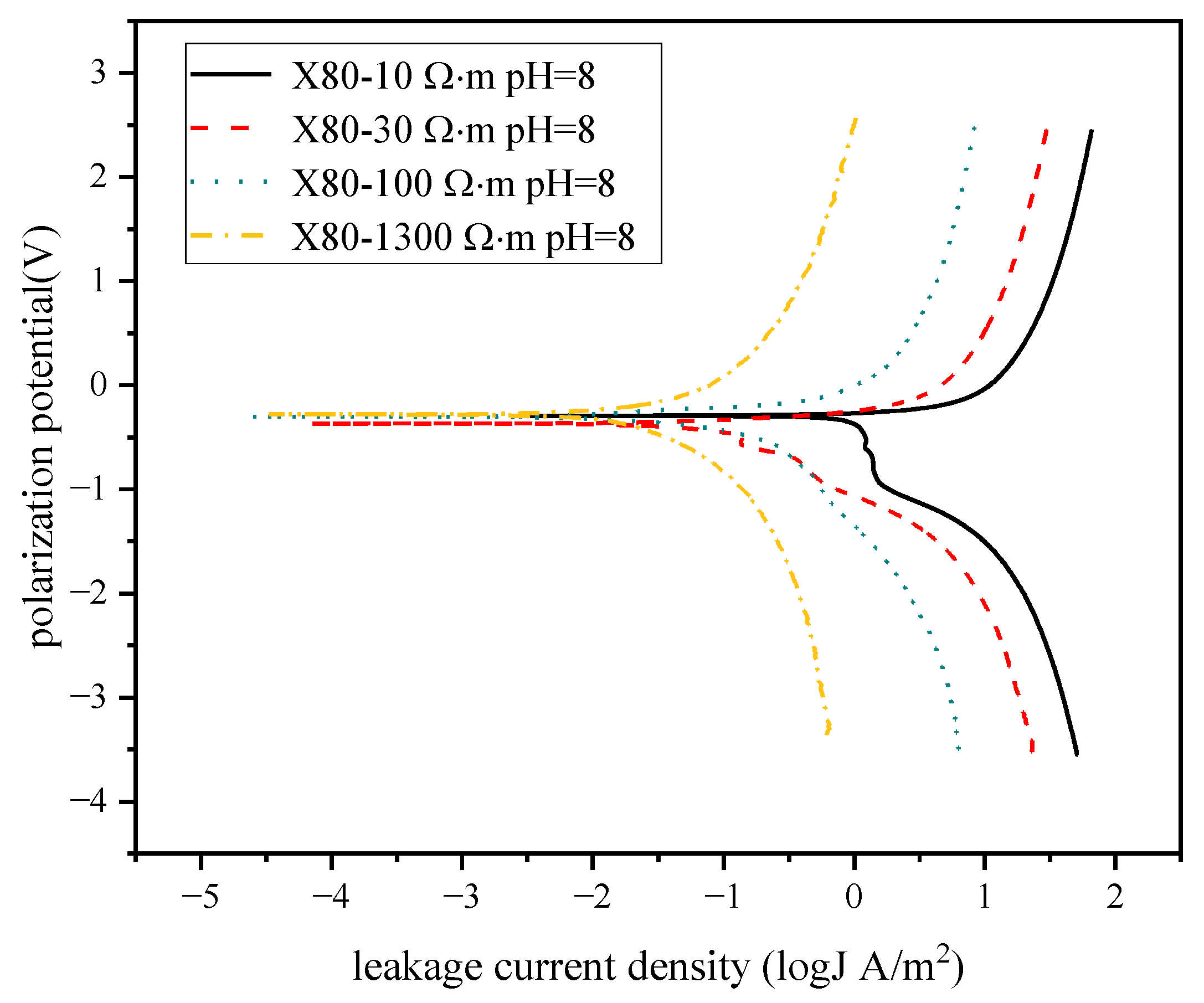
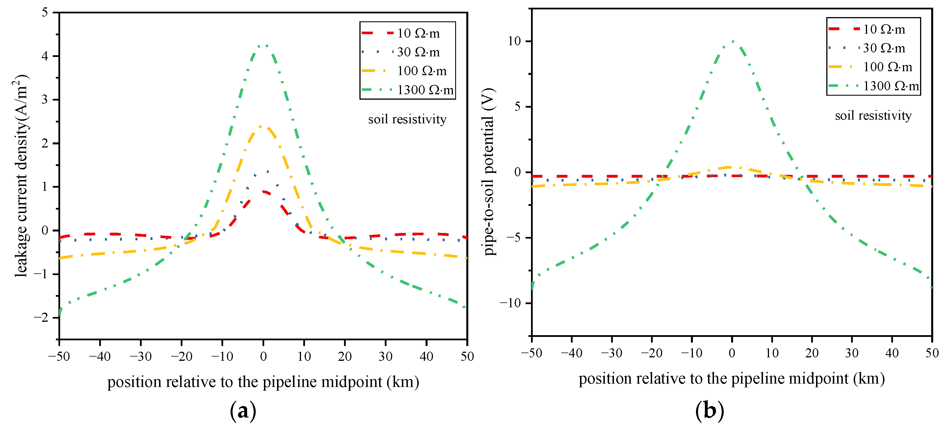
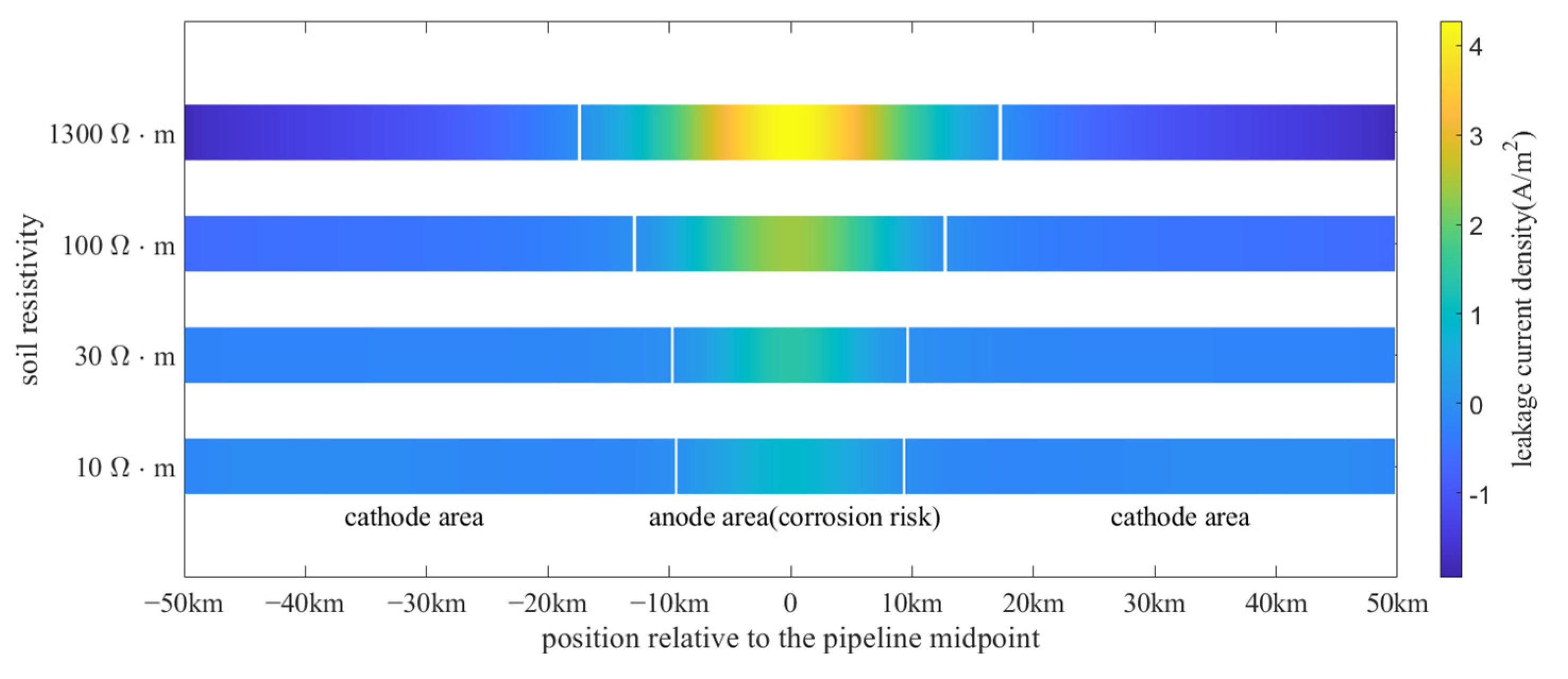
5.3. Soil Resistivity

Soil resistivity influences not only the grounding current flow path but also the polarization. Four soil resistivity types (10, 30, 100, 1300 Ω·m) were chosen for study. The HVDC grounding current is 3000 A. The other parameters are the same as those listed in Table 1. The polarization curves were measured under different soil conditions. Figure 14 shows the test polarization curve data.
The calculation results of leakage current density and PSP are shown in Figure 15.
The maximum leakage current density and PSP increase as the soil resistivity increases. Regression analysis shows that the relationship between the maximum leakage current density Jmax and the soil resistivity ρs satisfy logarithmic function, that is J max = a 3 ln ( ρ s ) + b 3 . a3 and b3 are fitting constant coefficients.
Figure 16 shows the interference range for the anode area and cathode area along the pipeline for different distances between the electrode and pipeline.
The results indicate that the anode area range extends as the soil resistivity becomes higher. Both the maximum leakage current density and corrosion risk area are positively correlated with the soil resistivity. Therefore, it is very important to evaluate the interference level accurately when dealing with highly resistive soil conditions.

6. Conclusions

(1)
A methodology based on a combination of MoM and FEM is proposed for calculating the coupling voltage and current on buried pipelines induced by grounding currents while taking into account nonlinear polarization. The validity of the calculation method was verified by experiment.
(2)
Both the maximum leakage current density and maximum PSP increase as the grounding electrode current increases. The relationship between the maximum leakage current density and the electrode grounding current is linear. The corrosion area becomes more concentrated as the grounding current increases.
(3)
The maximum leakage current density increases exponentially when the distance between electrode and pipeline decreases. The distance between the electrode and pipeline has a significant influence on the corrosion area range. The corrosion area range increases substantially as the distance increases, whereas the influence degree decreases substantially.
(4)
The maximum leakage current density and PSP increase as the soil resistivity increases. The relationship between the maximum leakage current density and the soil resistivity satisfies the logarithmic function. Both the maximum leakage current density and corrosion risk area are positively correlated with the soil resistivity.

Author Contributions

X.L. conducted theoretical research, characteristics computation, and wrote the paper; F.B. and F.C. are responsible for the experiment design and data analysis; C.L. gave some good advice during the experiments and paper writing. All authors have read and agreed to the published version of the manuscript.

Funding

This research received no external funding.

Informed Consent Statement

Not applicable.

Acknowledgments

The authors would like to thank the State Grid UHVDC Test Site of China for providing the experiment environment.

Conflicts of Interest

The authors declare no conflict of interest.

References

  1. Liu, L.; Yu, Z.; Jiang, Z.; Hao, J.; Liu, W. Observation research on the effect of UHVDC grounding current on buried pipelines. Energies 2019, 12, 1279. [Google Scholar] [CrossRef] [Green Version]
  2. Verhiel, A.L. The effects of high-voltage DC power transmission systems on buried metallic pipelines. IEEE Trans. Ind. Gen. Appl. 1971, 3, 403–415. [Google Scholar] [CrossRef]
  3. Gong, Y.; Xue, C.L.; Yuan, Z.L.; Li, Y.X.; Dawalibi, F.P. Advanced analysis of HVDC electrodes interference on neighboring pipelines. J. Power Energy Eng. 2015, 3, 332–341. [Google Scholar] [CrossRef]
  4. Ying, B. The influence on safe operation of the long-distance pipeline of electrode of high voltage direct current transmission system. Oil-Gasfield Surf. Eng. 2014, 33, 23–24. (In Chinese) [Google Scholar]
  5. Hardie, D.; Charles, E.; Lopez, A. Hydrogen embrittlement of high strength pipeline steels. Corros. Sci. 2006, 48, 4378–4385. [Google Scholar] [CrossRef]
  6. Yang, C.; Li, J.; Li, Z.; Zhang, S.; Dai, L.; Zhang, C. Study on interference and protection of pipeline due to high-voltage direct current electrode. Corros. Rev. 2019, 37, 273–281. [Google Scholar]
  7. Lorena-de, A.-R.; Villanueva-Balsera, J.; Ortega-Fernandez, F.; Rodriguez-Perez, F. Methods to Evaluate Corrosion in Buried Steel Structures: A Review. Metals 2018, 8, 334. [Google Scholar]
  8. Hopper, A.T.; Gideon, D.N.; Berry, W.E. Analysis of the Effects of High-Voltage Direct-Current Transmission Systems on Buried Pipelines; Technical Toolboxes: Houston, AK, USA, 1967. [Google Scholar]
  9. Nicholson, P. Study details HVDC stray-current effects on pipelines. Oil Gas J. 2010, 108, 74–78. [Google Scholar]
  10. Lagace, P.J.; Houle, J.; Greiss, H.; Mukhedkar, D. Computer aided evaluation of pipeline current near toroidal HVDC ground electrodes. IEEE Trans. Power Deliv. 1989, 4, 216–222. [Google Scholar] [CrossRef]
  11. Yu, Z.; Liu, L.; Wang, Z.; Li, M.; Wang, X. Evaluation of the interference effects of HVDC grounding current on a buried pipeline. IEEE Trans. Appl. Supercond. 2019, 29, 1–5. [Google Scholar] [CrossRef]
  12. Giao, T.N.; Sarma, M.P. On the potential and field distribution around a ground electrode for HVDC transmission. IEEE Trans. Power Appar. Syst. 1971, PAS-90, 2793–2801. [Google Scholar] [CrossRef]
  13. Dawalibi, F.; Mukhedkar, D. Multi step analysis of interconnected grounding electrodes. IEEE Trans. Power Appar. Syst. 1976, 95, 113–119. [Google Scholar] [CrossRef]
  14. Dawalibi, F.; Pinho, A. Computerized analysis of power systems and pipelines proximity effects. IEEE Trans. Power Deliv. 1986, 1, 40–48. [Google Scholar] [CrossRef]
  15. Zhang, B.; Cao, F.; Meng, X.; Liao, Y.; Li, R. Numerical approach of impressed potential on buried pipelines near high-voltage DC grounding electrodes. IET Gener. Transm. Distrib. 2018, 12, 1177–1182. [Google Scholar] [CrossRef]
  16. Stern, M.; Geary, A.L. Electrochemical polarization: I. A theoretical analysis of the shape of polarization curves. J. Electrochem. Soc. 1957, 104, 56. [Google Scholar] [CrossRef]
  17. Marzinotto, M.; Mazzanti, G.; Nervi, M. Ground/sea return with electrode systems for HVDC transmission. Int. J. Electr. Power Energy Syst. 2018, 100, 222–230. [Google Scholar] [CrossRef]
  18. Zoski, C.G. Handbook of Electrochemistry; Elsevier: Amsterdam, The Netherlands, 2006. [Google Scholar]
  19. Stansbury, E.E.; Buchanan, R.A. Fundamentals of Electrochemical Corrosion; ASM International: Almere, The Netherlands, 2000. [Google Scholar]
  20. Newman, J.; Thomas-Alyea, K.E. Electrochemical Systems; Wiley: New York, NY, USA, 2004. [Google Scholar]
  21. NACE-TM0497. Measurement Techniques Related to Criteria for Cathodic Protection on Underground or Submerged Metallic Piping Systems; NACE International: Houston, TX, USA, 2002. [Google Scholar]
Figure 1. Interference process of HVDC electrode currents on pipelines.
Applsci 12 04433 g001
Figure 2. Typical three-electrode system for measuring polarization curves.
Applsci 12 04433 g002
Figure 3. Schematic diagram of the boundary value problem.
Applsci 12 04433 g003
Figure 4. Layout of the scale experiment system.
Applsci 12 04433 g004
Figure 5. Test points layout along the pipeline.
Applsci 12 04433 g005
Figure 6. Test circuit based on external coupon method.
Applsci 12 04433 g006
Figure 7. The relationship between polarization potential and current density for the X80 pipe steel under 100 Ω m , pH = 8 soil condition.
Applsci 12 04433 g007
Figure 8. Results of test and calculation. (a) leakage current density along the pipeline; (b) pipe-to-soil potential along the pipeline.
Applsci 12 04433 g008
Figure 9. Schematic diagram of the pipeline and HVDC grounding electrode arrangement.
Applsci 12 04433 g009
Figure 10. Calculation results under different HVDC grounding currents. (a) leakage current density along the pipeline; (b) PSP along the pipeline.
Applsci 12 04433 g010
Figure 11. Corrosion risk area distribution under different grounding currents.
Applsci 12 04433 g011
Figure 12. Calculation results under different distance between electrode and pipeline. (a) leakage current density along the pipeline; (b) PSP along the pipeline.
Applsci 12 04433 g012
Figure 13. Corrosion risk area distribution for different distances between HVDC electrode and pipeline.
Applsci 12 04433 g013
Figure 14. Polarization curve under different soil resistivity.
Applsci 12 04433 g014
Figure 15. Calculation results under different soil resistivity. (a) leakage current density along the pipeline; (b) PSP along the pipeline.
Applsci 12 04433 g015
Figure 16. Corrosion risk area distribution under different soil resistivity.
Applsci 12 04433 g016
Table 1. Parameters for the study model.
ParametersValue
HVDC grounding current100 A, 500 A, 1000 A, 2000 A, 5000 A
pipeline length100 km
distance between electrode and pipelines10 km
soil parameters100 Ω·m, pH = 8
pipeline steel materialX80
pipeline coating resistivity3.3 × 107 Ω·m
Publisher’s Note: MDPI stays neutral with regard to jurisdictional claims in published maps and institutional affiliations.

