Article

Masonry Spiral Stairs: A Comparison between Analytical and Numerical Approaches

1
Department of Civil Engineering, University of Salerno, Via Giovanni Paolo II, 132, 84084 Fisciano, Italy
2
Department of Architecture and Industrial Design, University of Campania Luigi Vanvitelli, Via San Lorenzo-Abazia di San Lorenzo, 81031 Aversa, Italy
3
Department of Structural Engineering, University of Naples ‘Federico II’, Via Claudio, 21, 80125 Naples, Italy
*
Authors to whom correspondence should be addressed.
Appl. Sci. 2022, 12(9), 4274; https://doi.org/10.3390/app12094274
Submission received: 28 March 2022 / Revised: 20 April 2022 / Accepted: 20 April 2022 / Published: 23 April 2022
(This article belongs to the Special Issue Theory and Modelling of Historic Masonry Architecture)

Abstract

:
The present paper applies the Linear Arch Static Analysis (LASA), which models the masonry material as unilateral, i.e., No-Tension material in the sense of Heyman, and the Safe Theorem of the Limit Analysis to the study of masonry spiral stairs. A comparison is made with a refined FE analysis of the same problem, obtained by means of the ANSYS Parametric Design Language (APDL). The objective is to prove that LASA can be a valid alternative to other more complex numerical methods, such as FE, especially when the modeling parameters, such as the boundary conditions, cannot be exactly defined. The case study of a small spiral staircase placed in the tower of Nisida, a small island close to Naples, Italy is taken into consideration. The results show that the LASA analysis provides results that fall within two limit FE cases in terms of stress and overall thrust, providing at the same time a meaningful insight into the equilibrium state of the structure.

1. Introduction

1.1. The Spiral Stair throughout History: Brief Notes

Spiral staircases constitute one of the elements that better define the evolution of masonry construction throughout modern history. Since ancient times, different materials and construction techniques have also marked the building typology of spiral stairs, especially with respect to its geographical position and construction time. The oldest known examples of spiral stairs in the Western hemisphere date back to the first centuries of our era and are associated with funerary or civil and Roman construction. Choisy [1] describes a group of spiral staircases built between the 4th and the 8th Centuries covered by helical vaults; spiral staircases of the Middle Ages evolved from these ancient vaults. Viollet le Duc [2] also describes these stairs as formed by a stonecutting buttress, within a circular case, helicoidal non-bonded stone vault, supported by the central buttress and the case masonry. These vaults support the steps in which edges are traced along the circle radius. Between the 9th and 12th centuries, several spiral staircases were built in ashlar stonework. Among them is the transept stairs of Saint Gilles’ Abbey (Figure 1a), identified as the archetypal and one of the most intricate stereotomic models in stonemasonry art, described widely in all stonework treatises until the nineteenth century. From the 13th century, these types of stairs with central buttresses became much more common. They can be related to those of the vis de Saint Gilles type, but they include typical features of Gothic constructions. Ancient architects and engineers used them to connect small tricky passages and rooms and connect buildings vertically and horizontally. These horizontal and vertical connections, skillfully placed into the buttresses, supports and corners of the structures, were uniquely Gothic innovations. In the second half of the 15th century a group of stairs appeared (see Figure 1b) in the Mediterranean area, whose central buttresses ascended creating a radial molding allowing light to pass through this central cavity.
Despite their practical origin, these stairs turn into the main aspects of the building composition and its space. In the United States of the 20th century, the ultimate expression of this technique is represented by the work of the architect Rafael Guastavino [3] who, inspired by the Catalan vaults, built thin spiral staircases made of a few clay tiles (Figure 1c).

1.2. Current State of the Research

As seen above, masonry spiral staircases have always been a challenge for architects and engineers in order to understand their structural behavior, primarily due to the complexity of their geometry. In the last decades, extensive research has been carried out to elaborate numerical models with different degrees of complexity capable of describing the non-simple behavior of masonry structures under external loads. However, this is an open issue, and a unique recognized analysis procedure applicable to any problem concerning masonry structures has not yet been found. Several numerical approaches for the analysis of masonry structures based on Discrete Element Method (DEM) and Finite Element Method (FEM) have been introduced in recent years [4,5,6], despite their well-known limitations in the case of complex models [7]. In fact, the application of known solutions arising from the elastic analysis of helical beams [8] or shells [9] is not readily applicable to helical staircases in masonry due to material modeling and boundary conditions [10]. Several methods for modeling masonry structures have been developed within Heyman’s theory of Limit Analysis (LA), considering the masonry as rigid-unilateral material that can resist compressive loads but not tensile loads. Starting from the foremost works [11,12], the extension of traditional frame LA [13] approaches to the No-Tension (NT) materials has been widely discussed in the literature [14,15,16], and many studies have focused on this theoretical assumption, applying it to different types of historical vaulted constructions [17]) to vaults and domes. With respect to spiral staircases, some studies have also been conducted on solutions involving torsional actions. In this sense, the first approach was the one provided by Heyman, based on the equilibrium of a series of rigid interlocking blocks. As Heyman remarked [18], the primary structural action for a small, cantilevered staircase (quarter or half landing) is the twist of the individual steps. This action generates shear stresses in the masonry, which are low for short staircases but become increasingly problematic for long flights. Heyman’s solution can be defined as the superimposition of two balanced distributions of vertical forces consisting of the self-weight of the single block, or the applied load, and of the contact force transmitted by the previous one. By combining these two equilibrium conditions, the whole stair can be studied by analyzing in sequence all the steps from the top to the bottom, leading to an increase in torsion and of the associated shear stresses in steps. According to this solution, Price and Rogers [19] considered the effect of beating, looking into the possibility of interacting oblique forces for decreasing the torsional effect significantly, but without providing any formal solution. Similar considerations can be drawn from the solution proposed by Angelillo in [20] for the analysis of helical staircases composed of monolithic steps interacting only through the internal rib. This different model combines Heyman’s equilibrium solution with a ring-like solution valid only for a generic helical stair structure fixed at both ends. It is shown as the torsional Heyman’s mechanism, combined with a Ring-Like regime, gives rise to large compressive forces and to moderate torsional torques, whose intensity reaches a plateau for long flights too. Heyman’s solution is valid for stairs of moderate flight, and the Ring-Like solution is valid for stairs constrained at both ends, or equivalently, to stairs whose ends are subject to convenient compressive axial forces. Combining the two models implies using the Heyman’s equilibrium solution in a first sector springing from the top (minimal amplitude) and the Ring-Like solution in the remaining part of the stair. This leads to reasonable shear and tensile stresses into the steps and reasonable compressive stresses into the central rib for any flight of the helical stair. Despite the complexity of this model, confirmation of the complementarity of Heyman and Ring-Like stress regimes is achieved in [21] for the case study of the triple-helical stair of San Domingos de Bonaval, by employing a discrete model formed by rigid pieces, which are the steps of the stair. This complex multi-body model gives a reasonable solution for displacements and internal forces by applying the energy criterion. The challenge of finding equilibrated solutions for non-tensile materials has led to the development of increasingly advanced models based on the definition of a unilateral membrane entirely contained within the thickness of the masonry structure. This approach was first adopted for the analysis of masonry vaults in [22] (also see [23,24,25]) and then successfully used for the analysis of helical staircases in [26,27]. García Ares in [28] proposed a solution for spiral staircases by considering that longitudinal thrust lines interact with the transversal funicular curves that convey the vertical loads through the supporting walls. Block introduced the Thrust Network Analysis (TNA) in [29] to study an equilibrium solution for this typology of stairs, which can also be applied to a variety of masonry assessment cases [5].

1.3. Purpose of the Study

The present paper starts by the use of the Linear Arch Static Analysis (LASA) in order to obtain an equilibrium solution in compression for masonry spiral staircases, and more generally, for non-planar curves under a given vertical load [30]. The case study of the small spiral staircase placed in the tower of Nisida, described in Section 3 is taken into consideration. The results are compared with those obtained by using a FEM model, since this is the standard method in everyday engineering practice. Given the uncertainty of the FE modeling, especially with respect to the boundary conditions, as it is the case even in much more undefined schemes [31,32], two different limit cases are analyzed. The comparison between the LASA results and the FE ones show that the first method is able to provide a reasonable and reliable solution to the problem avoiding the complexity of the FE analyses. The last section summarizes and discusses the significant outcomes of this study. Actually, it is shown that LASA can be a valid alternative in the static evaluation of simple masonry structures with respect to other more complex methods.

2. Materials and Methods

Structural analysis of masonry constructions can generally involve two alternative approaches: equilibrium-based methods and deformation-based methods. The complexity and appropriateness of each procedure is related to the peculiarity of masonry material, which exhibits an high strength under compression compared to its weak strength under tension, unilateral contact and friction, in-homogeneity, and anisotropy due to the presence of joints [33,34]. In order to illustrate the equations that will be used in Section 3.2 and the parameters that will be employed in the discussion of the results, in this Section the basic elements of the Linear Arch Static Analysis (LASA) are presented in some detail.

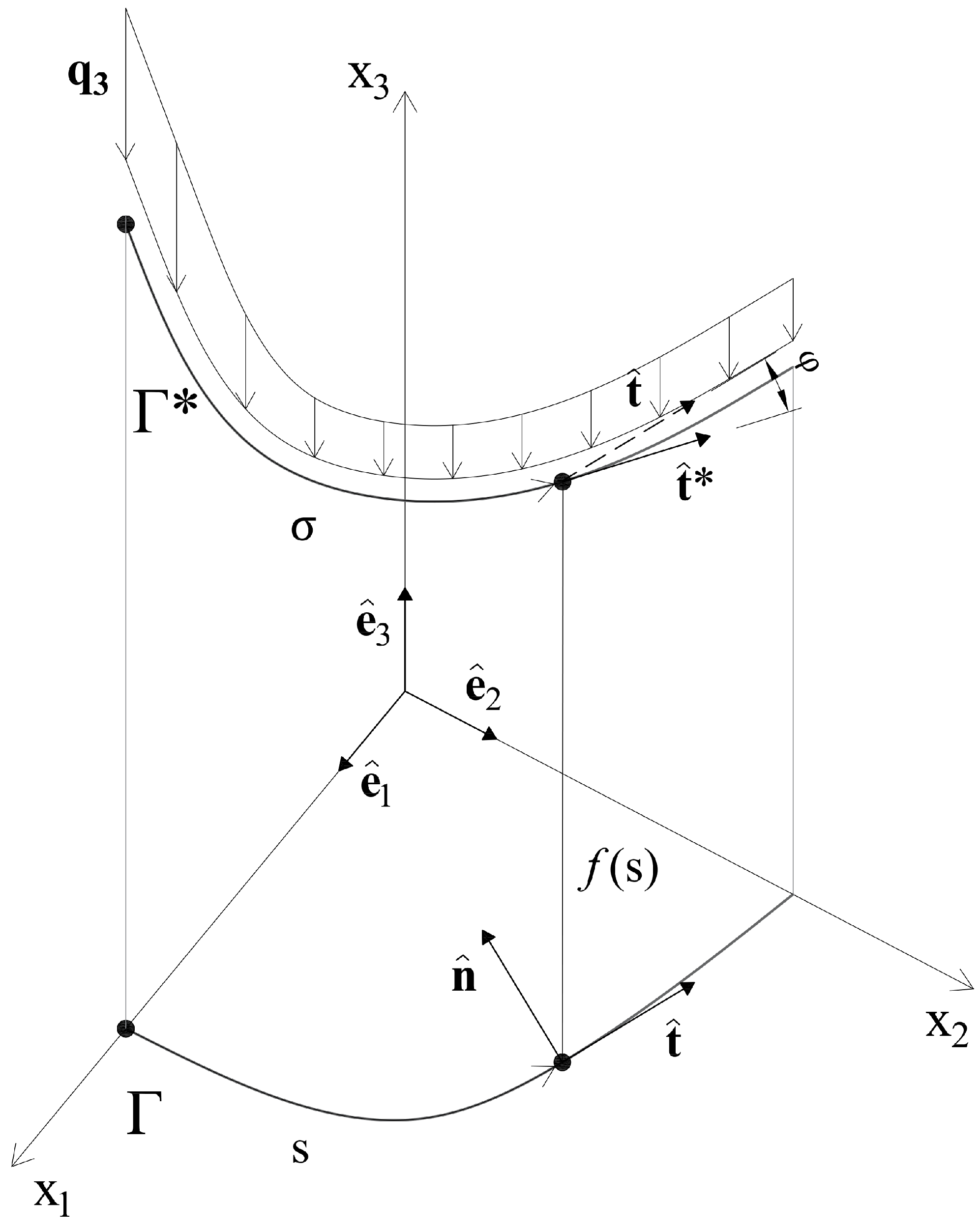
2.1. Linear Arch Static Analysis (LASA)

Angelillo et al. [30] show that the LASA provides an equilibrium solution in compression for a given vertical load over a given non-planar curve. This equilibrium solution assumes that a set of 1D space linear arches, considered circular or elliptical helixes confined by the exterior wall, carry the load from the top to the ground. The whole notion behind the LASA is that developed by Pucher for membranes [35]; it implies solving the equilibrium on the plan-form to determine the stresses in the spatial structure. In such a way, it is possible to consider Linear Arches, of prescribed geometry, as a family of line coordinates along which the equilibrium of vertical load q is written (a sort of lattice) contained inside the stair. In the approximate solution, a number n of such lines will be considered. Each structural line Γ * carries an axial force N that must be compressive ( N 0 ) for the blocks to interact unilaterally.

2.1.1. Geometry

In Figure 2 the 1D space Linear Arch Γ * and its plane projection Γ onto the plan-form Ω are depicted. Both Γ and Γ * are parametrized with the arc length s along Γ . Referring to the same figure for the notation, we have:
Γ = x = x ( s ) , s 0 , L ,
Γ = x = x ( s ) + f ( s ) e ^ 3 , s 0 , L ,
L being the length of the curve Γ , and the elevation f ( s ) being a continuous function.
The tangent and normal unit vectors to the plane curve Γ can be defines as:
t ^ = d x d s , n ^ = e ^ 3 × t ^ ,
and, the unit tangent vector along Γ * as:
t ^ = cos φ t ^ + sin φ e ^ 3 .
Finally,
d t ^ d s = ρ n ^ ,
where ρ is the curvature of Γ .

2.1.2. Forces

We consider an external force q per unit length acting on Γ *:
q = q t t ^ + q n n ^ + q 3 e ^ 3 .
We also introduce the load per unit projected length along Γ :
p ˜ = J q , p ˜ = J q t t ^ + J n ^ + J q 3 e ^ 3 p t = J q t , p n = J q n , p 3 = J q 3 ,
By calling φ the angle between t ^ and t ^ (see Figure 2), the Jacobian is defined as J = 1 / cos φ . Naming T the concentrated stress along Γ *, the axial force N along Γ * is defined through the relation
T = N t ^ t ^ .
In equilibrium, the axial force N must balance the load q applied to the line, i.e., it must satisfy the six cardinal equations of statics for a rigid body. Besides, assuming that N must be compressive, then, we also have the constraint N 0 . Referring to [30] for the derivation of the equilibrium equations and naming S the so-called thrust force, we obtain the two planar
S + p t = 0 , ρ S + p n = 0 ,
and the transversal equation
S f + S f + p 3 = 0 .
Since S = N cos φ , and π / 2 φ π / 2 , the unilateral restriction N 0 , entails the condition S 0 .

2.1.3. Solution of the Equilibrium Problem for the Curve Γ *

By considering f as given, one can obtain the solution for S by integrating Equation (10):
S = 1 f 0 s p 3 ( s ) d s + S 0 f ( 0 ) ,
where S 0 is a boundary value for S at s = 0 . Then, substituting back into the first of Equations (9), p t is derived:
p t = S = 1 f 0 s p 3 ( s ) d s + S 0 f ( 0 ) .
Finally, from the second of Equation (9):
p n = ρ S = ρ f 0 s p 3 ( s ) d s S 0 f ( 0 ) .

3. Application to the Case Study

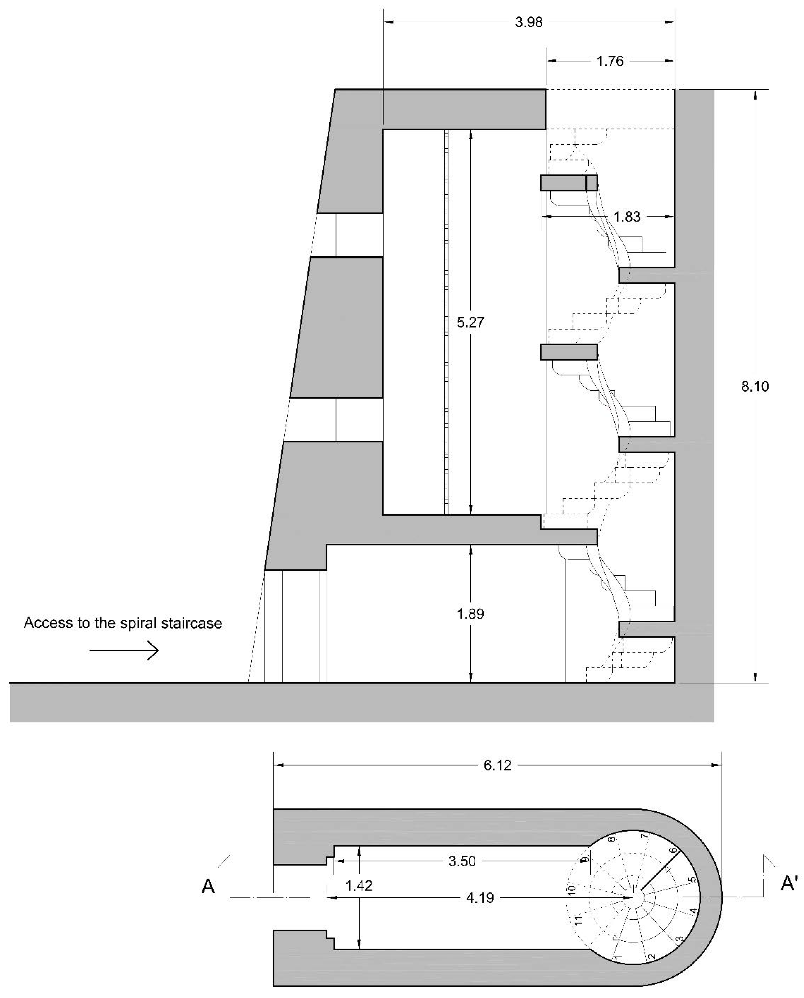
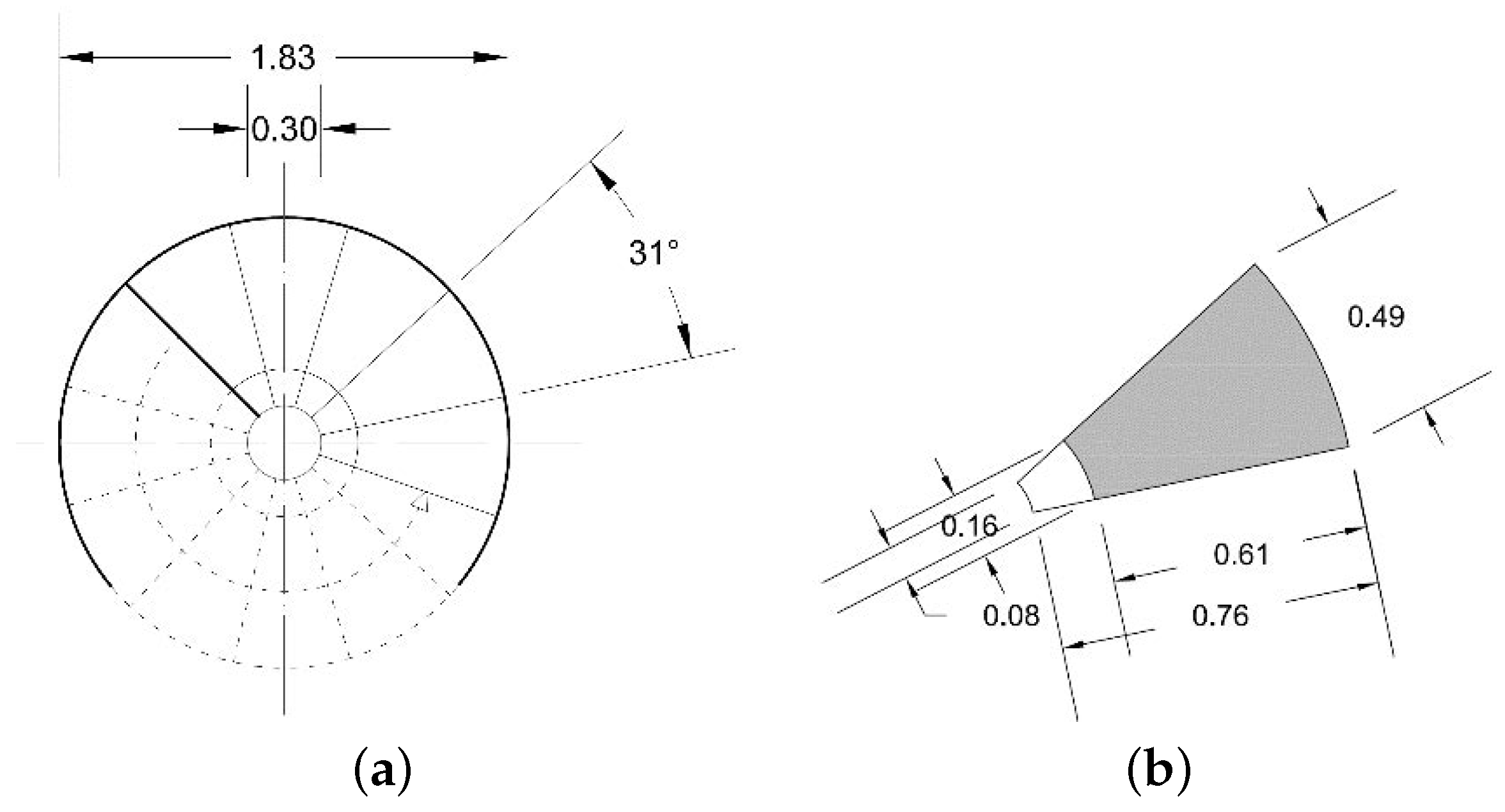
3.1. The Spiral Staircase in the Fortified Tower of Nisida: Geometry and Construction

Nisida is the smallest and closest island to Naples. A cylindrical watchtower was built on top of the island in the Angevin period. For several centuries, the pictorial view of Nisida has been characterized by the ancient tower, which is one of the most critical and prominent architectural buildings of the Phlegraean area. It was long-abandoned and reused as a prison in the early decades of the nineteenth century; it was then definitively abandoned after the Second World War.
The tower structure has changed drastically, mainly due to the 19th-century reformations and the 20th-century partial demolition; all that remains of the coastal defense building today is the sole scarp The current access is through a spiral stair, located inside this scarp, dating back to the end of the 19th century, and leading to the only remaining room on the upper floor.
The analysis of the small spiral staircase with a central hole is the case study of the present work. It has a circular plan of 1.83 m in diameter, and it resides in a “well” (e.g., the circular perimeter structure containing the spiral staircase), a vertical void of 8.10 m in height. The perimeter wall is in tuff masonry covered with plaster. Along the staircase, there are two empty windows for lighting and ventilation (Figure 3). The stair consists of 36 steps that rest on the helical pillar and it rises by rotation, so that the transmission of loads through the central support is somehow compromised. The steps are made of cut stone with a rise of 21 cm, 61 cm wide without considering the part of the step embedded in the wall of the staircase cylinder [36].
Figure 4 and Figure 5 show the geometry of the spiral staircase; Table 1 summarizes its main geometric parameters with respect to the drawings of Figure 5.

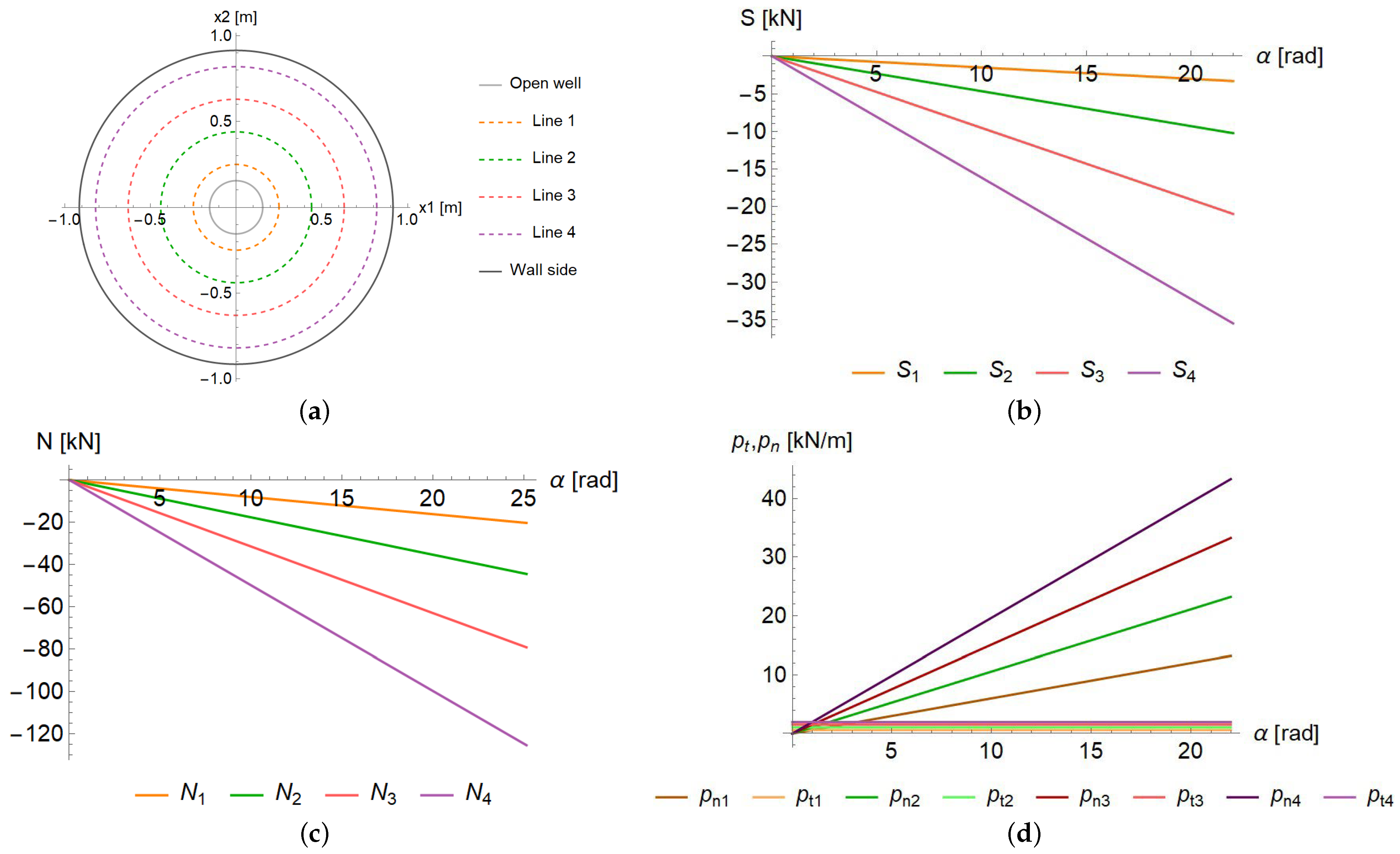
3.2. LASA Equilibrium Solution

As shown in Section 2.1, a discrete number of Linear Arches can be considered within the stair in order to model, by means of uniaxial stress along that arches, the transmission of the given vertical load to the supporting structures. Obviously, the number and the geometry of the family of Linear Arches should take into account the way in which the steps are in contact with each other. There are cases where the steps, made of monolithic stone blocks, are in contact only along an internal rib (for example, the stair of San Domingo de Bonaval analyzed in [21]), and thus a single linear arch must be considered. If this is not the case, a number of Linear Arches can be accounted for, taking into account that the class of compressive equilibrium solutions enlarges as more and more arches are assumed. A balance between the two competing demands for richness of solutions and reasonable computational effort must be found. The choice of a convenient inter-spacing is obviously related to the minimum transverse dimension of the step. For a non-monolithic stair, say a tile vault made of bricks, this width is also dependent on the size of the bricks and of their arrangement.
For the analysis shown below, referred to a stair made of monolithic steps, four spiral Linear Arches ( n l = 4 ) spaced apart 0.19 m from each other have been considered (see Figure 6b).
The steps of the stair are made of stone with a specific weight ρ = 25.5 kN/m 3 , so we consider a distributed load q = 8.0 kN/m 2 , taking into account the self-weight.
The geometry of the four linear arches Γ i , of projected radius r i and total projected length L i , can be described as follows
Γ i = x i = r i cos s i r i e ^ 1 + r i sin s i r i e ^ 2 + f i ( s i ) e ^ 3 , s i 0 , L i ,
where the functions f i ( s i ) are assumed linear, and described by the expression:
f i ( s i ) = 4 H 1 s i L i .
In order to represent the results, it is convenient to introduce the non-dimensional variable α = s i / r i to express both the geometric and force variables.
Writing Equation (11) in terms of α
S i ( α ) = 1 f i Q α r i + S 0 ,
where Q = q L s t e p 4 is the load for unit projected length carried by each linear arch. The maximum thrust value occurs at line 4 at the bottom end of the line and its value is S m a x = 35.5 kN (see Figure 6b).
To obtain the normal forces N i ( α ) we project back the thrusts S i ( α ) on the lines
N i ( α ) = S i ( α ) 1 + f i ( α ) 2 ,
In Figure 6c the plots of N i as a function of α is reported.
The maximum normal force value, that is the maximum value of the thrust transmitted by one step to the one below, occurs in line 4 at the bottom of the stair, and its value is N m a x = 45.6 kN. To obtain the tangential and the normal components of the horizontal force per unit length that is transmitted through the steps to the wall, Equations (12) and (13) can be written as a function of α :
p n i ( α ) = ρ i ( α ) S i ( α ) ,
p t , t o t = i p t i ( 8 π ) ,
The corresponding plots are reported in Figure 6d.
The maximum values of the normal and tangential components, evaluated at the end of the stair, are: p n , t o t = 113.0 kN/m and p t , t o t = 5.1 kN/m, and the value of the modulus of their resultant is p t o t = 113.1 kN/m.
Referring to Figure 7, the stresses in the wall and in the bottom tread at the end of the stair are checked using Equations (21) and (22):
σ w , m a x = p t o t L s w 1 L s w b m .
σ s t e p , m a x = N m a x 1 L s t e p , i b m .
Their values are σ w , m a x = 0.54 MPa and σ s t e p , m a x = 1.72 MPa, respectively. If we consider that both the stair and the wall are made of tuff with an average crushing limits of 20 MPa [37] and an admissible stress value of σ a d m = 20 / 3 MPa, by using
χ w a l l = σ a d m σ w , m a x , χ s t e p = σ a d m σ s t e p , m a x ,
we have a loading capacity ratio for the wall and for the step respectively of χ w a l l = 12.3 and χ s t e p = 3.9 .

3.3. Analysis with FEM

Modeling, simulations and FEM analysis were performed by means of the Finite Element package Ansys® (Ansys 2019) [38]. Given the complexity of the model, an ad hoc algorithm was written in the programming language Ansys Parametric Design Language (APDL). The geometrical model used in the numerical simulations (Figure 3b) has been identified on the basis of observations surveys carried out by the authors and summarized in Figure 4 and Figure 5 and Table 1. On account of the helicoidal symmetry of the stair, efforts have been made to design and generate the geometry of the step with a central support zone, in order to represent the spiral staircase. In particular, some parameters like the step rise, the inner and outer radii of curvature delimiting the walkable surface, the angle defined by each step as well as the number of them, have been used to generate the parametrical model. The first step has been fixed at the ground and a rigid behavior has been assigned to the surfaces between adjacent steps by imposing appropriate constrain equations. The physical model was discretized using 249,000 linear tetrahedral elements, i.e., SOLID 185, and 57,000 nodes with three translational degrees of freedom each.
Mechanical properties: for the sake of simplicity, the behavior of masonry was assumed to be elastic with the following values for the modulus of elasticity, the Poisson modulus and the density of the material, respectively: E = 21 GPa, ν = 0.3 , ρ = 25.5 KN/m 3 .
Boundary conditions: given the uncertainty related to the connection of the stairs to the surrounding wall, the analyses were carried out with reference to two different sets of boundary conditions representing the limiting cases through which the real behavior of the stair of Nisida can range:
  • Clamped boundary conditions: the base of the first step from the ground is clamped and the horizontal displacements U x and U y of the upper step (36th step) are prevented. Each intermediate step is embedded into the outer wall.
  • Sliding boundary conditions: the base of the first step from the ground is clamped and the horizontal displacements U x and U y of the upper step (36th step) are prevented. Each intermediate step is linked to the outer wall by a sliding condition, i.e., it cannot detach from the wall but it is free to slide along its surface.
Load conditions: in the numerical simulation the structure was assumed subjected to its self-weight.

Results

Figure 8 summarize the results of the numerical analyses in terms of principal stresses and stair by stair thrust. The stress state is in the range of masonry cracking and average crashing limits (i.e., 2–20 MPa) and this fact makes the choice of an elastic material a posteriori admissible. The difference between the two limit cases is evident: in the case of clamped stairs the modulus (intensity) of the thrust line results much lower than in the case of the sliding boundary conditions, as it is physically expectable and in line with the results from the LASA analysis. This is because the actual behavior of the structure will lay somehow between the two limit boundary conditions. On the other hand, Figure 8 highlights how the stresses transmitted by one step to the one below according to FE change with respect to the boundary conditions and result helicoidally sketched, as it is expectable, when no support derives from considering the steps embedded into the wall. Overall, the averaged numerical values are comparable to those deriving from the LASA analysis Figure 9.

4. Discussion

The numerical analyses provide a similar stress distribution in the direction of the steps, with stress values that increase as we move from the open-well to the wall side and that are always compatible with the masonry cracking and crashing limits. Paying attention to the stress distributions along the stair it is possible to notice some differences between the two FE models (Figure 9). In fact, the stress status in the case of sliding boundary conditions grows starting from the top of the stair and going to its base, as it is the case in the LASA results, while in the case of clamped steps, the stress status results much more uniform along the vertical developments of the stair. The similarity of the sliding model with the LASA is due to the fact that the LASA considers an arch-like behavior of the structure, with the normal forces along the direction of the stair, and consequently the stresses transmitted through the steps to the wall increase from top to bottom. On the contrary, the clamped FEM model considers the steps essentially as cantilevered from the wall and does not take into account the thrust increase that occurs from top to bottom.

5. Conclusions

Because of the complexity of spiral staircases geometry, their structural behavior represents an exciting but difficult challenge in the field of masonry structures. This paper proposed a comparative analysis between two different approaches for the static assessment of masonry spiral staircases composed of monolithic steps. The first one is the Linear Arch Static Analysis (LASA) which models the material as unilateral, i.e., as NT in the sense of Heyman, and employs the Safe Theorem of the LA. The second one involves a geometrically complex Finite Element analysis (FE). The case study of a spiral staircase located in the tower of Nisida (Italy) has been analyzed. The comparison of the results indicates a reasonable agreement between the two proposed analyses, provided the FE boundary conditions are properly modeled. More specifically, both the LASA and FEM analysis provide stress values compatible with the masonry cracking and crashing limits with increasing values of the stress moving from the open-well side to the wall, but with a stress distribution along the stair that denotes a different structural behavior depending on the particular FE model. In view of the above, the LASA, though less detailed, looks simple, effective, and easy to be interpreted. LASA appears as a method extremely simple to be implemented, requiring as input data only geometric parameters to solve a system of three partial differential equations, but, it provides results in terms of maximum stress values comparable to much more complex FE analyses, which require a very complex input data set in terms of 3d geometry and boundary conditions. In fact, these data are in particular difficult to define properly on account of the uncertainties about the real restraint conditions at the surrounding wall. It is important to underline that the LASA is an extension of the classical Catenary solution in which both the load and the shape of the thrust line (linear arch) are assigned. The most important challenge of the method is to identify a curve able to transmit the loads in pure compression. In other words, the LASA can be successfully applied to the design or equilibrium assessment of any masonry vaulted structure provided that the constraints are able to withstand the normal and tangential stress components ( p n and p t ).

Author Contributions

C.O.: data curation, formal analysis, methodology and writing original draft & review & editing; C.C. (Claudia Cennamo): supervision; C.C. (Concetta Cusano): investigation and writing—original draft; A.C.: formal analysis, software and validation; A.F.: supervision; I.M. conceptualization, supervision, writing original draft & review & editing and visualization. All authors have read and agreed to the published version of the manuscript.

Funding

This research received no external funding.

Institutional Review Board Statement

Not applicable.

Informed Consent Statement

Not applicable.

Conflicts of Interest

The authors declare no conflict of interest.

Abbreviations

The following abbreviations are used in this manuscript:
FEMFinite Element Method
LALimit Analysis
LASALinear Arch Static Analysis
NTNo-Tension
TNAThrust Network Analysis

References

  1. Choisy, A. L’art de bâtir Chez les Byzantins: Planches; Librairie de la Société Anonyme de Publications Périodiques; Arnaldo Forni Editore: Bologna, Italy, 1883; Volume 1. [Google Scholar]
  2. Viollet-le Duc, E.E. Dictionnaire Raisonné de L’architecture Française du XIe au XVIe Siècle; Banc Bance: Paris, France, 1854; Volume 1. [Google Scholar]
  3. Ochsendorf, J. Guastavino Vaulting: The Art of Structural Tile; Princeton Architectural Press: New York, NY, USA, 2010. [Google Scholar]
  4. Betti, M.; Galano, L.; Vignoli, A. Finite Element Modelling for Seismic Assessment of Historic Masonry Buildings. In Earthquakes and Their Impact on Society; D’Amico, S., Ed.; Springer International Publishing: Cham, Switzerland, 2016; pp. 377–415. [Google Scholar] [CrossRef] [Green Version]
  5. Rigó, B.; Bagi, K. Discrete element analysis of stone cantilever stairs. Meccanica 2018, 53, 1571–1589. [Google Scholar] [CrossRef]
  6. Mascolo, I.; Modano, M.; Amendola, A.; Fraternali, F. A Finite Element Analysis of the Stability of Composite Beams with Arbitrary Curvature. Front. Built Environ. 2018, 4, 57. [Google Scholar] [CrossRef] [Green Version]
  7. Guarracino, F.; Walker, A. Some comments on the numerical analysis of plates and thin-walled structures. Thin-Walled Struct. 2008, 46, 975–980. [Google Scholar] [CrossRef]
  8. Busool, W.; Eisenberger, M. Exact static analysis of helicoidal structures of arbitrary shape and variable cross section. J. Struct. Eng. 2001, 127, 1266–1275. [Google Scholar] [CrossRef]
  9. Calladine, C.R. A preliminary Structural Analysis of a Guastavino Spiral Staircase Shell. In History of Structures: Essays in the History of the Theory of Structures in Honour of Jacques Heyman; Instituto Juan de Herrera, Escuela Technica Superior de Arquitectura de Madrid: Madrid, Spain, 2006; Available online: http://publications.eng.cam.ac.uk/364877/ (accessed on 25 March 2022).
  10. Huerta, S. The analysis of masonry architecture: A historical approach: To the memory of professor Henry J. Cowan. Archit. Sci. Rev. 2008, 51, 297–328. [Google Scholar] [CrossRef] [Green Version]
  11. Kooharian, A. Limit Analysis of Voussoir (Segmental) and Concrete Archs. J. Amer. Concr. Inst. 1952, 49, 317–328. [Google Scholar]
  12. Heyman, J. The stone skeleton. Int. J. Solids Struct. 1966, 2, 249–279. [Google Scholar] [CrossRef]
  13. Fraldi, M.; Gesualdo, A.; Guarracino, F. Influence of actual plastic hinge placement on the behavior of ductile frames. J. Zhejiang Univ. Sci. A 2014, 15, 482–495. [Google Scholar] [CrossRef]
  14. Iannuzzo, A. Energy based fracture identification in masonry structures: The case study of the church of “Pietà dei Turchini”. J. Mech. Mater. Struct. 2019, 14, 683–702. [Google Scholar] [CrossRef]
  15. Fortunato, A.; Gesualdo, A.; Mascolo, I.; Monaco, M. P-Bézier energy optimization for elastic solutions of masonry-like panels. Int. J. Mason. Res. Innov. 2021, 7, 113–125. [Google Scholar] [CrossRef]
  16. Malena, M.; Angelillo, M.; Fortunato, A.; de Felice, G.; Mascolo, I. Arch bridges subject to pier settlements: Continuous vs. piecewise rigid displacement methods. Meccanica 2021, 56, 2487–2505. [Google Scholar] [CrossRef]
  17. Cennamo, C.; Cusano, C. Roman Masonry Stairways. Geometry, Construction and Stability. In Conference of the Italian Association of Theoretical and Applied Mechanics; Springer: Cham, Switzerland, 2020; pp. 1896–1909. [Google Scholar] [CrossRef]
  18. Heyman, J. The mechanics of masonry stairs. WIT Trans. Built Environ. 1970, 17. Available online: https://www.witpress.com/elibrary/wit-transactions-on-the-built-environment/17/10699 (accessed on 25 March 2022).
  19. Price, S.; Rogers, H. James sutherland history lecture-Stone cantilevered staircases. Struct. Eng. 2005, 83, 29–36. [Google Scholar]
  20. Angelillo, M. The equilibrium of helical stairs made of monolithic steps. Int. J. Archit. Herit. 2016, 10, 675–687. [Google Scholar] [CrossRef]
  21. De Serio, F.; Angelillo, M.; Gesualdo, A.; Iannuzzo, A.; Zuccaro, G.; Pasquino, M. Masonry structures made of monolithic blocks with an application to spiral stairs. Meccanica 2018, 53, 2171–2191. [Google Scholar] [CrossRef]
  22. Olivieri, C.; Angelillo, M.; Gesualdo, A.; Iannuzzo, A.; Fortunato, A. Parametric design of purely compressed shells. Mech. Mater. 2021, 155, 103782. [Google Scholar] [CrossRef]
  23. Fraternali, F.; Angelillo, M.; Fortunato, A. A lumped stress method for plane elastic problems and the discrete-continuum approximation. Int. J. Solids Struct. 2002, 39, 6211–6240. [Google Scholar] [CrossRef]
  24. Montanino, A.; Olivieri, C.; Zuccaro, G.; Angelillo, M. From Stress to Shape: Equilibrium of Cloister and Cross Vaults. Appl. Sci. 2021, 11, 3846. [Google Scholar] [CrossRef]
  25. Olivieri, C.; Fortunato, A.; DeJong, M. A new membrane equilibrium solution for masonry railway bridges: The case study of Marsh Lane Bridge. Int. J. Mason. Res. Innov. 2021, 6, 446–471. [Google Scholar] [CrossRef]
  26. Angelillo, M. Static analysis of a Guastavino helical stair as a layered masonry shell. Compos. Struct. 2015, 119, 298–304. [Google Scholar] [CrossRef]
  27. Gesualdo, A.; Cennamo, C.; Fortunato, A.; Frunzio, G.; Monaco, M.; Angelillo, M. Equilibrium formulation of masonry helical stairs. Meccanica 2017, 52, 1963–1974. [Google Scholar] [CrossRef]
  28. García Ares, J.A. Un enfoque para el análisis límite de las escaleras de fábrica helicoidales. In Proceedings of the Actas del Quinto Congreso Nacional de Historia de la Construcción, Burgos, Spain, 7–9 June 2007. [Google Scholar]
  29. Block, P.P.C.V. Thrust Network Analysis: Exploring Three-Dimensional Equilibrium. Ph.D. Thesis, Massachusetts Institute of Technology, Cambridge, MA, USA, 2009. [Google Scholar]
  30. Angelillo, M.; Olivieri, C.; DeJong, M.J. A new equilibrium solution for masonry spiral stairs. Eng. Struct. 2021, 238, 112176. [Google Scholar] [CrossRef]
  31. Mascolo, I.; Fulgione, M.; Pasquino, M. Lateral torsional buckling of compressed open thin walled beams: Experimental confirmations. Int. J. Mason. Res. Innov. 2019, 4, 150–158. [Google Scholar] [CrossRef]
  32. Nowak, R.; Kania, T.; Rutkowski, R.; Ekiert, E. Research and TLS (LiDAR) Construction Diagnostics of Clay Brick Masonry Arched Stairs. Materials 2022, 15, 552. [Google Scholar] [CrossRef] [PubMed]
  33. Cusano, C.; Montanino, A.; Zuccaro, G.; Cennamo, C. Considerations about the static response of masonry domes: A comparison between limit analysis and finite element method. Int. J. Mason. Res. Innov. 2021, 6, 502–528. [Google Scholar] [CrossRef]
  34. Cusano, C.; Montanino, A.; Olivieri, C.; Paris, V.; Cennamo, C. Graphical and analytical quantitative comparison in the Domes assessment: The case of San Francesco di Paola. Appl. Sci. 2021, 11, 3622. [Google Scholar] [CrossRef]
  35. Pucher, A. Über der spannungszustand in gekrümmten flächen. Beton Eisen 1934, 33, 298–304. [Google Scholar]
  36. Cennamo, C.; Cusano, C.; Angelillo, M. The spiral staircase in the fortified tower of Nisida. In Proceedings of the 12th International Conference on Structural Analysis of Historical Constructions—SAHC 2021, Online event, 29 September–1 October 2021. [Google Scholar]
  37. Adachi, T.; Ogawa, T.; Hayashi, M. Mechanical Properties of Soft Rock and Rock Mass. In Proceedings of the 10th International Conference on Soil Mechanics and Foundation Engineering, Stockholm, Sweden, 15–19 June 1981; pp. 527–530. [Google Scholar]
  38. Thompson, M.; Thompson, J. ANSYS Mechanical APDL for Finite Element Analysis; Butterworth-Heinemann: Oxford, UK, 2017. [Google Scholar]
Figure 1. (a) Interior view of the vis de Saint Gilles in Languedoc (France). Notice the inscriptions made by 17th-century stonemasons on the walls of its perimeter box. (b) The spiral staircase of the northwest tower of the Lonja of Palma de Mallorca (Spain). (c) Guastavino helicoidal tile stair in the First National Bank of Peterson, New York City, ca.1890 (Guastavino archive, Columbia University).
Applsci 12 04274 g001
Figure 2. Schematic view of the curve Γ * and its projection Γ on a horizontal plane.
Applsci 12 04274 g002
Figure 3. Helicoidal staircase of Nisida: (A) Photographs by the authors; (B) in silico geometrical model; (C) Helicoidal FE model of staircase.
Applsci 12 04274 g003
Figure 4. Spiral staircase in the tower of Nisida: plan and section (Unit: m). Survey and drawings by the authors.
Applsci 12 04274 g004
Figure 5. Spiral staircase in the tower of Nisida: (a) geometric layout; (b) plan of the step with dimensions (Unit: m).
Applsci 12 04274 g005
Figure 6. (a) Projected stair and line geometry for the spiral stair of Nisida; Plots of (b) thrust S i ( α ) , (c) normal force N i ( α ) , (d) tangential p t i ( α ) and normal p n i ( α ) components of the stress.
Applsci 12 04274 g006
Figure 7. Perspective view of a typical step with line 4 inside.
Applsci 12 04274 g007
Figure 8. Helicoidal staircase of Nisida: (A,B) 3th Principal stress (Unit: MPa) and Vector plot of the thrust in the case of clamped boundary conditions; (C,D) 3th Principal stress (Unit: MPa) and Vector plot of the thrust in the case of sliding boundary conditions.
Applsci 12 04274 g008
Figure 9. Helicoidal staircase of Nisida: comparison between the thrust corresponding to the line 4 (violet line in Figure 6a and Figure 7) obtained with LASA and FEM analyses. Note: dashed gray lines mark linear interpolation of data.
Applsci 12 04274 g009
Table 1. Spiral staircase in the tower of Nisida: synthesis of the main metric and dimensional parameters.
PLANtype:circular
rotation:laevorotatory
staircase diameter: 1.83 m
hole (eye) diameter: 0.30 m
step angle: 31
number of steps:36
STEPcentral hole solution:radial
total length ( L s t e p ): 0.76 m
usable length: 0.61 m
minimum width: 0.16 m
maximum width: 0.49 m
step height: 0.41 m
medium height ( b m ): 0.21 m
Publisher’s Note: MDPI stays neutral with regard to jurisdictional claims in published maps and institutional affiliations.

