1. Introduction
Telepresence can be defined in several ways. According to Minsky (1980) [
1], telepresence was defined as remote control tools in reference to teleoperation systems. Steuer (1992) [
2] has defined telepresence as the experience of feeling a presence by using the communication medium. Shih (1998) [
3] understands telepresence as the degree to which a user can feel their existence in a virtual space. In our modern time, telepresence can be defined as a technology that can provide the feeling of being present in another remote location which enables both a remote and a local user to communicate. The goal of telepresence is to create the feeling of being there or physically present with a remote person [
4]. It is possible to have telepresence through a natural-sized image of the person, a 3D representation of the user or their environment, or the interaction between the remote user and the local user. A visual sense can be created by several paradigms, including a remote person appearing in a local setting [
5,
6], a remote space that appears to be stretched beyond the local surroundings [
7,
8], as well as a local user who is immersed in a remote setting [
9,
10]. The 3D reconstruction method is significant to produce human representation. Telepresence combined with 3D reconstruction technology has the potential to alleviate many of the limits associated with standard video-based communication, such as limited natural movement in 3D space, situational awareness, gaze direction, and eye contact due to the fixed viewpoint of the remote participant’s camera, as supported by Pejsa et al. [
11] which has evaluated the comparison between traditional video communication such as Skype with their 3D reconstruction integrated with the telepresence system called Room2Room. The result findings show that their systems show significant improvement in presence and completion time. Fuchs, H. et al. [
12] also agrees that 3D reconstruction integrates with telepresence and can also offer the potential for remote collaboration, virtual 3D object manipulation, or exploring the remote site. Modern telepresence technologies enable persons in remote areas to virtually meet and interact with one another through the use of realistic 3D user representations.
While display technology has evolved, the ability of the display to replicate a 3D environment remains a critical component. People have been working to advance 3D display technology for years, and researchers have gathered and produced a variety of inventions in recent decades, as well as benefiting from technologies that involve the viewing of 3D components, such as 3D telepresence and virtual reality (VR). Holographic projection is regarded as one of the most promising true 3D display technologies in the near future. This technology can also be implemented in many different forms, such as holographic prisms [
13], Z-Holograms [
14], HMDs [
15], and others.
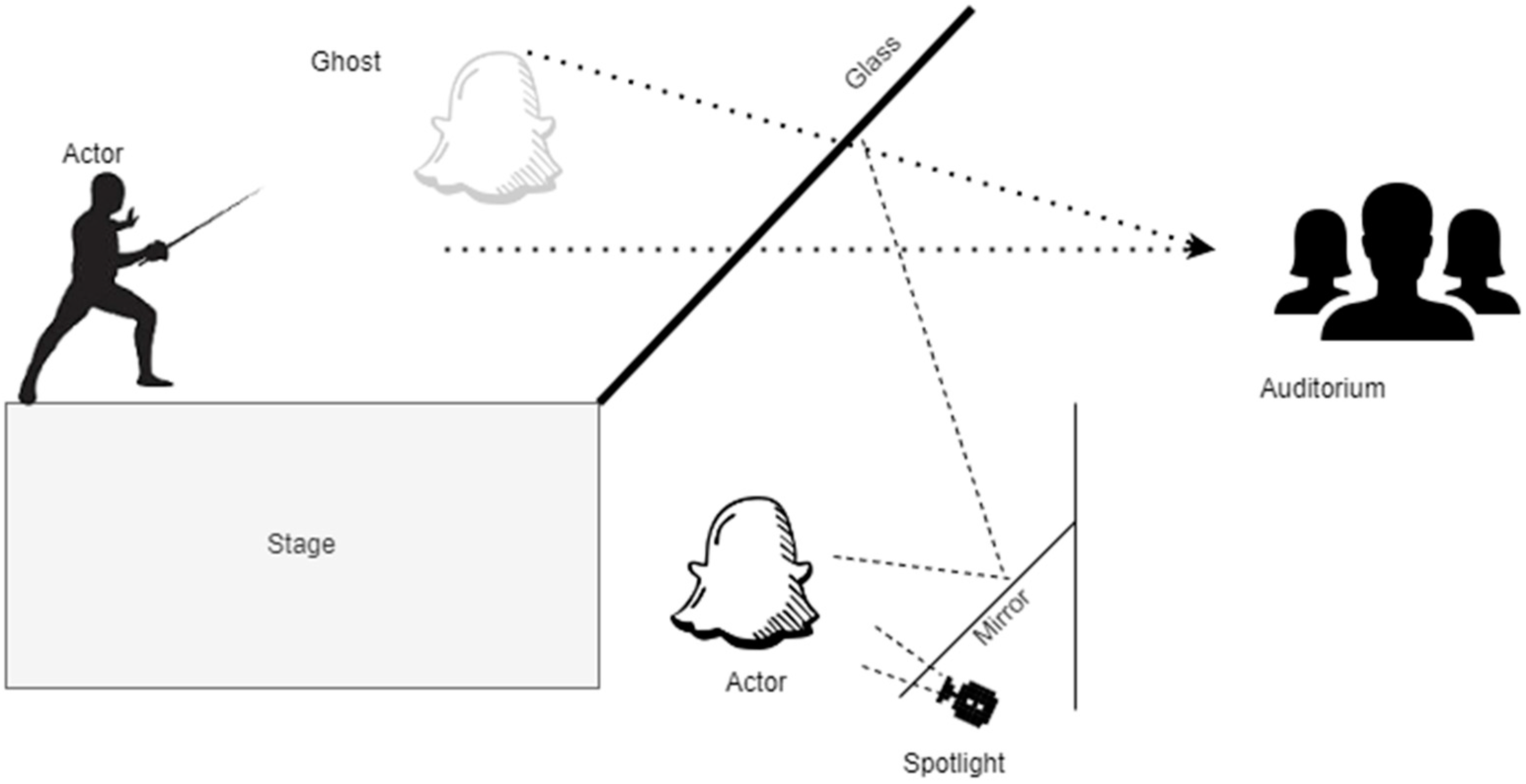
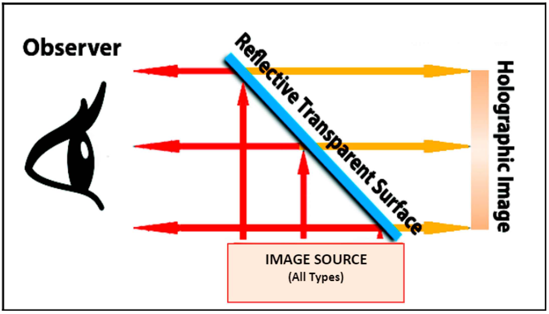
This study, however, wants to discard the use of any specialized equipment such as head-mounted displays to enable the remote user to move freely while interacting with the other user. This study shows the initial results of displaying the human 3D reconstruction using the Z-hologram display that incorporates the Pepper’s Ghost method to create the illusion as if the reconstructed user appeared as a 3D representation in the real-world environment. As demonstrated in
Figure 1, holographic projection technology is based on an illusionary method known as Pepper’s Ghost, which was initially utilized in Victorian theatres around London in the 1860s [
16]. A brightly lighted figure below the stage, hidden from the public’s view, is mirrored in a pane of glass between the performer and the audience. It appears to the audience that the ghost is present on stage. A hologram is a picture of interference and diffraction on the surface of a real 3D object captured on a specific optical film or glass from all point light sources of a projected target item [
17].
This research was inspired by earlier works related to 3D reconstruction for telepresence. Researchers have been intrigued by the prospect of 3D telepresence for decades, but because of technological limitations in the past, prototypes have only just begun to appear in the marketplace. Multiple cameras are deployed in prior works in order to build a 3D reconstruction of a room-scaled scene [
11], and their images are constantly changed to include the moving user, utilizing a variety of stereo reconstruction [
18] techniques. This enables the reconstruction of the scene into 3D representation. When inexpensive depth sensors, for instance, the Microsoft Kinect [
19], became widely available at low cost and were capable of acquiring video images as well as per-pixel depth information and were accessible, the total amount of studies and developments related to 3D reconstruction merged with telepresence systems increased substantially [
20]. Therefore, this paper further discusses the 3D reconstruction process involved to reconstruct a 3D representation of the captured user using RGB-D camera implemented with holographic telepresence. The test application and the results are also presented, and this paper ends with a conclusion.
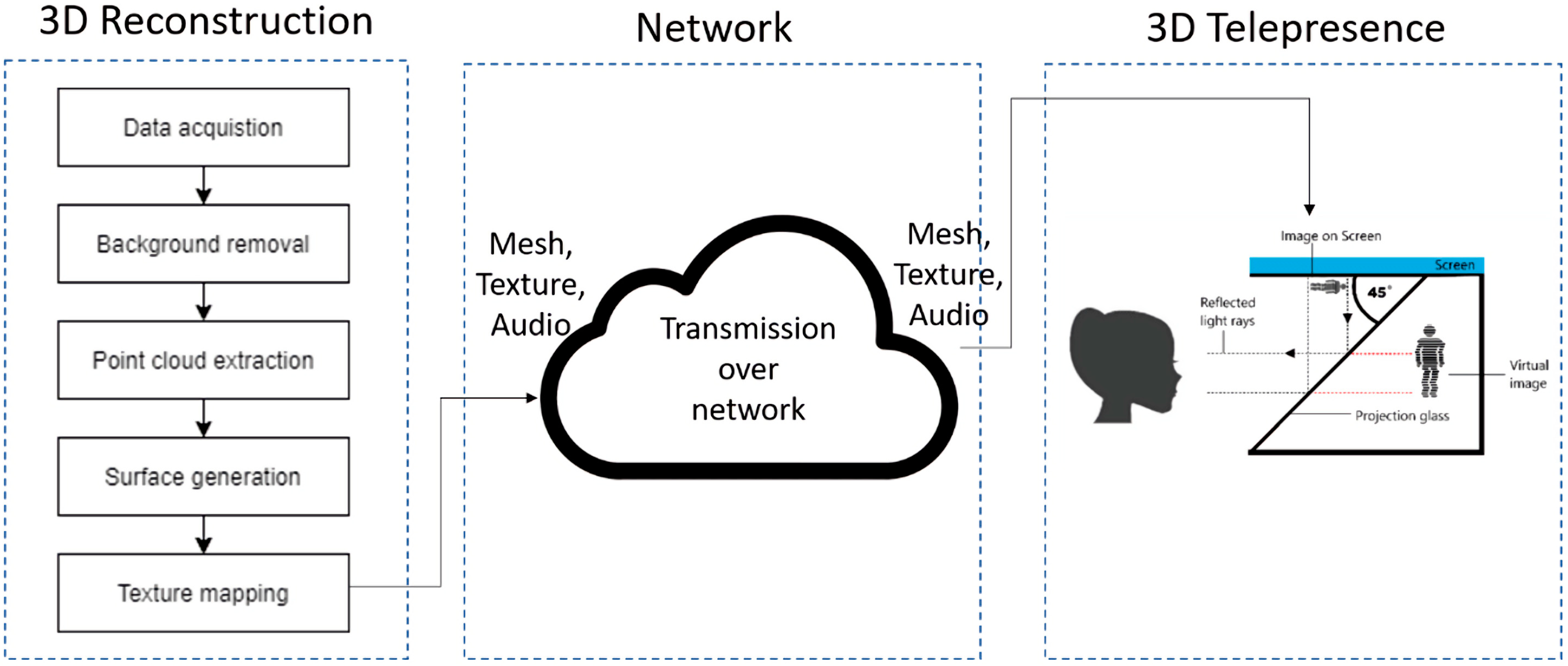
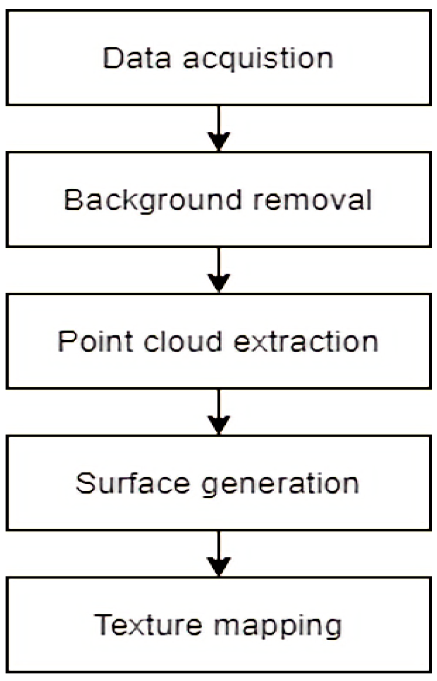
The first phase is designed to produce the real-time 3D reconstruction of the local user where the flow is as demonstrated in
Figure 2. When the data is obtained using the commodity depth sensor, which has been pre-processed, the next step is to remove the background in order to get the foreground mask which contains only the captured user’s body without the background. After we obtain the foreground mask of the captured data, the 3D point cloud is extracted. For the surface production of the 3D model, the marching cube algorithm is then used with point cloud data as the input. The resulting 3D model has then applied the texture mapping.
After the textured 3D model of the local user has been reconstructed, the data, which includes mesh, texture and audio, will be transmitted to the remote location through transmission over the network. The experimental setup for the 3D telepresence will then be set up for the test application.
2. Real-Time 3D Reconstruction Method
2.1. Data Acquisition
Microsoft Kinect V2 has been utilized to capture the local user in the data acquisition process. Data captured by depth sensors can be noisy and needs to be pre-processed to recover the missing depth values at some defective areas in the depth map. The depth holes can be filled by using a hole-filling algorithm [
21], after which the depth map will be smooth, using a bilateral filtering algorithm [
22]:
The depth information of the depth hole in the depth map can be filled using the hole-filling formula shown with m be a constant, where p(x,y) will be the filling target point, Dl presents the lth depth value, wn denotes the normalization parameter, and the w(xl,yl) is the weight coefficient. The hole in depth map will be filled through this hole-filling processing step. After this process, the traditional bilateral filtering algorithm is used to smooth the depth map with holes that have been filled.
Since the RGB-D cameras have been utilized, the instrument parameters for a general colour-depth sensor for 3D reconstruction are the distance difference and depth resolution. Distances between the reconstructed target points were compared to the ground truth measurements. Using Kinect, the object was then captured from two different distances to get measurements between 0.7 m to 2 m. RGB-D cameras and the corresponding depth used for scene reconstruction, then depth resolution was measured by moving the Kinect away (0.5–15 m) from a planar target in sufficiently fine steps to record all values returned in an approximately 5° view field around the image centre. Considering the depth resolution, when the depth image has been constructed by triangulation from the IR image, the depth resolution for triangulation-based devices such as the Kinect is expected [
23]. However, this paper is limited to explaining the marching cube algorithm for 3D reconstruction, therefore it does not provide the evaluation to count on instrument parameter for its accuracy.
2.2. Background Removal
An RGB-D camera has been utilized during the background removal process to capture the local user. The Kinect V2 sensors have captured the colour and depth images. From the depth image, the body index image contains a 2D grid where each coordinate gives a simple 0 to 5 integer representing which body the sensor associates with that coordinate.
The background removal from the depth image to generate the body index image is required as this research only focuses on reconstructing the human. Thus, the foreground extraction step is needed and can be done by segmenting the foreground pixels from the background pixels in depth images. In order to extract foreground pixels, the foreground or background information is converted into binary ones and zeros, respectively.
The body index image includes the instance segmentation map for each body in the depth camera capture. Each pixel maps to the corresponding pixel in the depth or IR image. The value for each pixel represents which body the pixel belongs to. It can be either background or the index of a detected body. We obtained the human body segmentation mask using this body index image mapped together with the colour image.
2.3. Point Cloud Extraction
In this research, we used two Kinects, and the multiple sensors were used simultaneously. In order to obtain the 3D points, the [x, y, z] coordinates of each pixel inside the human body segmentation mask used perspective projection with z = depth. Then, the [x, y, z] points were projected onto the colour frame using the intrinsic and extrinsic parameters of the colour camera to extract the corresponding colour of each 3D point.
The 3D-coloured points (
X,
Y,
Z,
R,
G,
B) of each depth pixel using perspective projection are obtained using the following equation.
where (
) is the principal point and f is the focal length. To fuse the coloured 3D data, the extrinsic parameters of each camera, i.e., the poses between each camera and the reference will be used to transform all the point clouds into a single reference frame. The next step is to refine the initial estimate of the extracted point cloud using iterative closest points (ICP) [
24] with Algorithm 1.
| Algorithm 1: Iterative Closest Point (ICP) |
Input: F1...n—3D point cloud from each sensor
Data: R1...n, t1...n—initialized to identity
Result: R1...n, t1...n—refinement transform for each sensor
v = 1; τ = 0.01; firstPass = true; e = 0; ê = 0
Step:
while v > τ do
e = 0
for i = 1 do
K = {1, 2, ..., n} \ i
/* ICP aligns the i-th shape to all the other ones, updates
Ri, ti and returns the average error per point */
e = e + ICP(FK, Fi, Ri, ti)
end
if firstPass == true then
firstPass = false
v = 1
else
.
end
ê = e
End |
We want to construct, within each cube, a 3D model that is usually constituted by a triangular mesh that correctly represents the geometry and topology of the isosurface. The surface generation from point cloud data will later be implemented with the extended marching cube algorithm, which requires a discrete set of cubes as mentioned in Custodio et al. [
25]. ICP has been used to divide the input volume into a discrete set of cubes. This is the primary reason the ICP can avoid degenerate triangles and guarantee topological correctness during the surface generation stage.
2.4. Surface Generation
Next, the surface generation from point cloud data that has been extracted is the process where the unorganized points in the point cloud were connected and generated a set of triangles that closely approximates a surface of interest. The Marching Cube algorithm takes voxel data and extracts an isosurface, a polygonal mesh surface representation. Each voxel has a value, and the marching cube algorithm attempts to create a mesh for the surface at a specified iso value. When it comes to an isosurface, the implicit function f(x,y,z) = c is generally what defines it. This means that all 3D points in the volume part of a c-surface satisfy the previous criterion. When we use Marching Cubes, the 3D volume is divided into voxel squares of equal size. The predefined triangular pattern is possible. A triangular pattern is applied to voxels that intersect the isosurface to approximate the course of the isosurface within the cell.
In this research, discrete point cloud data are processed using the techniques presented in Hoppe et al. [
26]. We decided to use this algorithm because it would provide insight into the fundamental concepts behind several existing surface reconstruction methods. It was possible to reduce the algorithm’s complexity by using a set of points on an unknown surface with their normals. The Marching Cube algorithm has been proven by Stotko et al. [
27], who claim that it is very compact and easily manages the data which has and can be a benefit for telepresence, which requires immediate transmission as well as fast and compact data structures to allow for reconstructing and providing a virtual 3D model in real time to remote users. Kowalski et al. [
24] agreed that the enhancement needed to produce a fast and inexpensive 3D data acquisition system for multiple Kinect sensors.
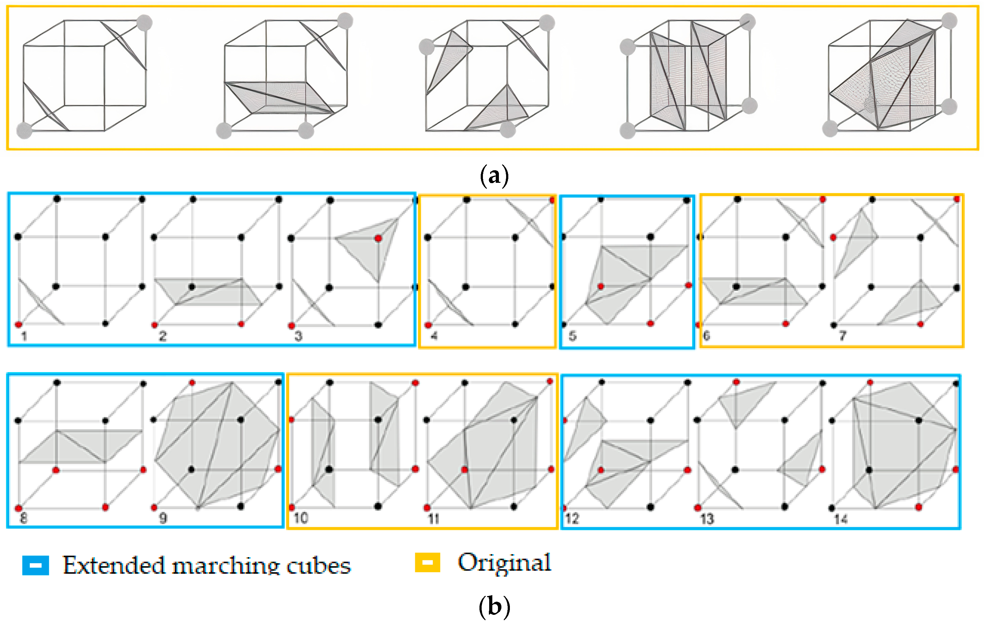
The modification of the Marching Cube algorithm is based on [
25]. In Algorithm 2, the step in number 7 is used a looping foreach voxel recalculating and generating process. The cube vertices are insufficient to determine the correct surface triangulation. The original marching cube does a lookup into one of eight different cases as in the yellow frames in
Figure 3a that shows as the 4th, 6th 7th, and 10th and 11th cubes in the modified lookup table. Modifying the marching cube to triangulate the implicit surface allows the possibility of the prescribing boundaries to increase, and it becomes sufficient. Extended marching cubes then look at each voxel’s boundaries and do a lookup into one of 14 different cases in blue frames, as shown in
Figure 3b. The mesh associated with the looked-up case is added in place of the voxel. After all voxels have been processed, the result is a set of mesh triangles that approximate the mesh from which the point cloud was created.
| Algorithm 2: Marching Cube |
Input: Sampling dataset with , marching cube vertex,
Output: surface which approximates , a list of vertices to be rendered with their respective normals.
Step:
1. Examine for each point in the local neighbourhood, set of nearest neighbours
2. Compute best approximating tangent plane
3. Find normal for each sample point
4. Compute z as the projection of onto
5. if the distance to the sample point is nearest to z do
return sign of the distance function, as positive
6. else
return sign of the distance function, as negative
7. while > 0
for each voxel (cube) of the dataset do
Calculate an index to the cube, by comparing the cube vertex’s
v, 8 density values to the iso value, h
Verify the edges list from a lookup table by using the
calculated index.
Linearly interpolate to find the surface-edge intersection based
on the scalar values in each vertex of the edge.
Using of central differences method [28] to compute a unitary
normal in each cube vertex. Interpolate each triangle vertex’s
normal
Return the vertex normal and the triangle vertices.
8. end for
9. end while
End |
2.5. Texture Mapping
Texture mapping can help produce a visually appealing model by applying high-quality textures on a 3D mesh with minimal geometric complexity, as claimed by [
29]. Additionally, it is necessary to consider that voxel-based 3D reconstruction methods generate, on average, fewer triangles and vertices than the depth map’s initial 2D resolution in pixels, depending on the number of voxels [
29]. Therefore, using a colour-per-vertex approach results in colour aliasing, leading to insufficient quality. We use complete texture mapping to address this matter, which entails projecting vertex points onto colour images to get the UV coordinates. The texture is then assigned per triangle as suggested in [
30].
A process involving transformation from 3D mesh vertices v = (x,y,z)T > ∈ V in relation to an object space into a texture coordinate t = (u,v)T ∈ Ω_T on a 2D texture image T: Ω_T → R3 is known as texture mapping. Using UV coordinates to define a triangle or fragment permits the storage of many texels (texture elements) t ∈ Ω_T, each of which holds an RGB colour value. After we had the reconstructed 3D model, the model’s vertices were projected onto the colour image planes to acquire colour correspondences in the neighbouring colour frame, resulting in a textured 3D model.
3. Proposed Real-Time 3D Reconstruction for Holographic Telepresence
After the real-time 3D reconstruction phase has been done, the next step is to enable the 3D telepresence. The textured 3D model of the local user produced was then transferred to a remote location through the network to be displayed at a remote location in real-time to enable the local and remote user to engage with one another through the telepresence. The overall framework of the proposed real-time 3D reconstruction for a 3D holographic telepresence is shown in
Figure 4.
The textured 3D model, along with the audio of the local user, is then transmitted over the network to the remote location, as in
Figure 5. These data will first be encoded to be compressed according to the suitable bandwidth of data transmission through an internet protocol. After the data was sent and received at the remote location, the data was decompressed using a lossless compression method on the remote client laptop and ready to be displayed in the reconstructed textured 3D model of the local user. The lossless compression method used for this research is the Lempel-Ziv-Free (LZF) compression, as recommended by Waldispühl et al. [
31]. This compression algorithm requires a minimal code space and working memory. The mesh data with audio input of remote users was also sent over to the local location through the network.
Once the data sent from the local site were received on the remote site, the mesh data was rendered and displayed using holographic projection. As illustrated in
Figure 6, Z-Hologram was chosen as the display device to project the virtual reconstructed local user onto a real-world environment for remote users to experience and interact with it.
For Z-Hologram, the effect of floating virtual 3D images for the viewers is formed when the reference beam and the object or image source beam are incident on opposite sides of the reflective transparent surface, as illustrated in
Figure 7. The beams interfere and record an image called a holographic image. To reconstruct the image, a point source of white light illuminates the hologram from the proper angle, and the viewer looks at it from the same side as the light source.
As agreed with by Oh and Kwon [
32], the hologram technique can enhance the realism and the immersion to provide the realizable 3D stereoscopic vision when the floating hologram projecting the 2D image to represent the 3D image in the air uses the glass panel. Yang et al. [
33] also claimed that, using the Pepper’s Ghost principle, a 2D image satisfying certain psychological depth cues such as occlusion can be displayed, thereby providing the viewers with 3D feelings. Thus, the 3D data that has been generated and displayed using the Z-hologram can be perceived by the user in 3D and helps provide a more absorbing experience of viewing the 3D data for the user. Using Z-hologram can benefit from 3D data as it able to provide the viewer with 3D impressions without the use of wearable hardware. Besides, a VR headset does not support a holographic display because any object inside VR is considered as a virtual object. Holographic projection is when the object is projected onto the real-world. This article also mentions that the use of hardware can restrict user movement and cause discomfort to the user.
4. Results and Discussion
This section explains the experimental setup for real-time 3D reconstruction for 3D telepresence. The test application of our work will be further explained in this section as well.
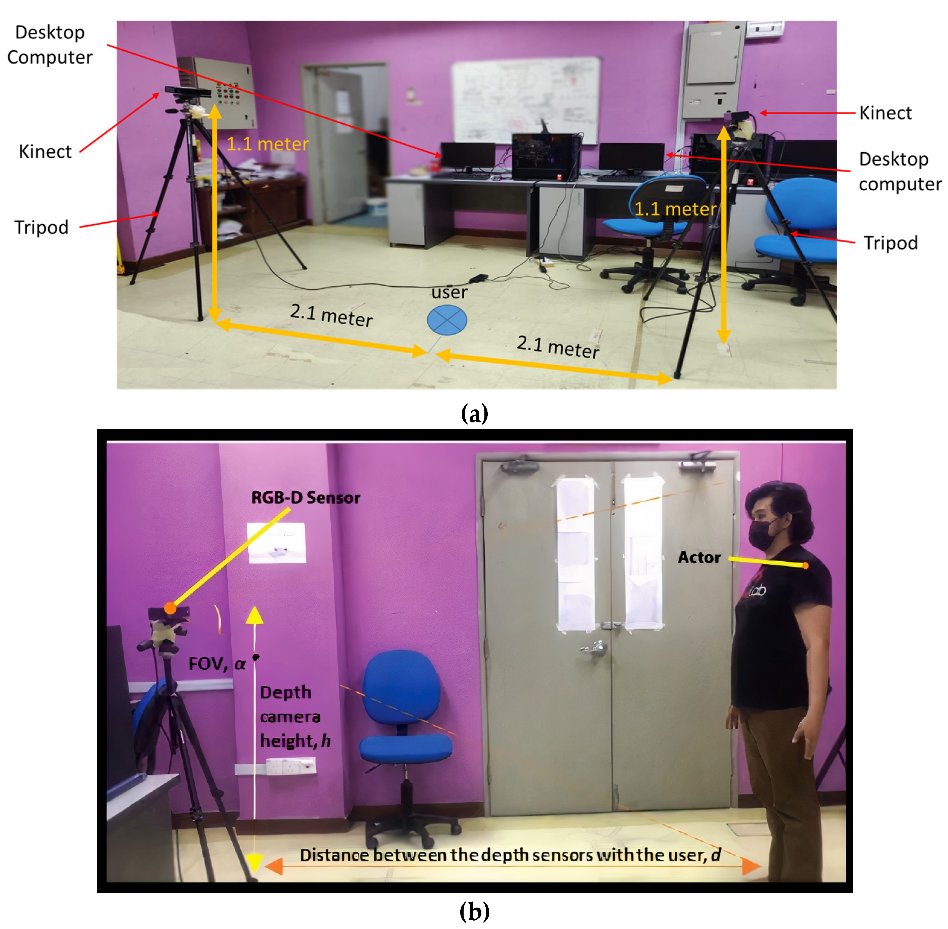
The experimental setup is presented in
Figure 8a, which shows equipment such as desktop computers, a Kinect and a tripod, as well as its placement used for data acquisition of the local user in
Figure 8b. An RGB-D camera was placed with appropriate height,
h at the distance,
d, for enabling data acquisition using the Kinect V2 to gather the depth image and colour image of the depth used for life-sized 3D reconstruction. The depth camera field of view (FOV), α° will be set to a suitable angle to enable the life-size capture of the local user’s full body.
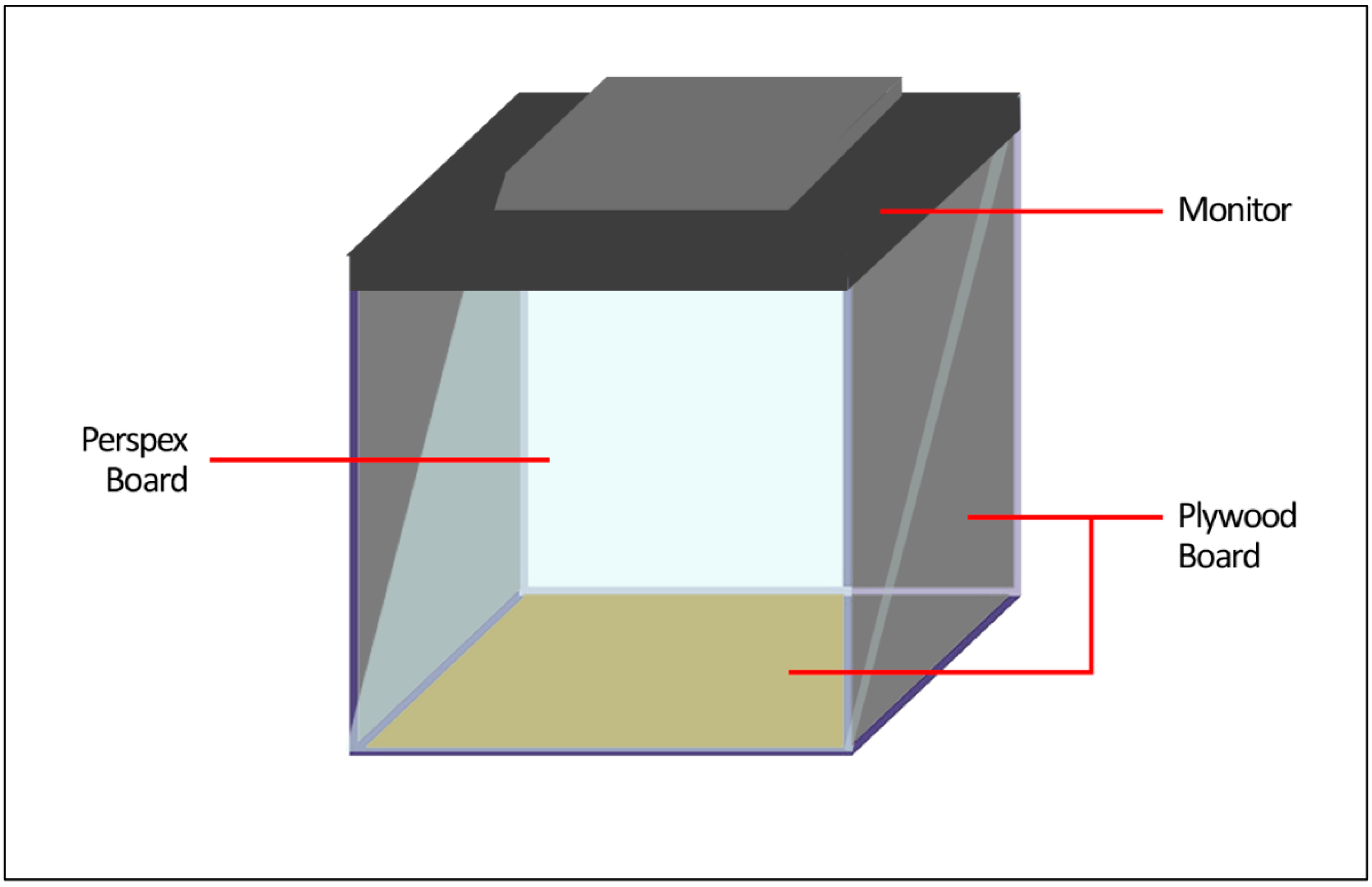
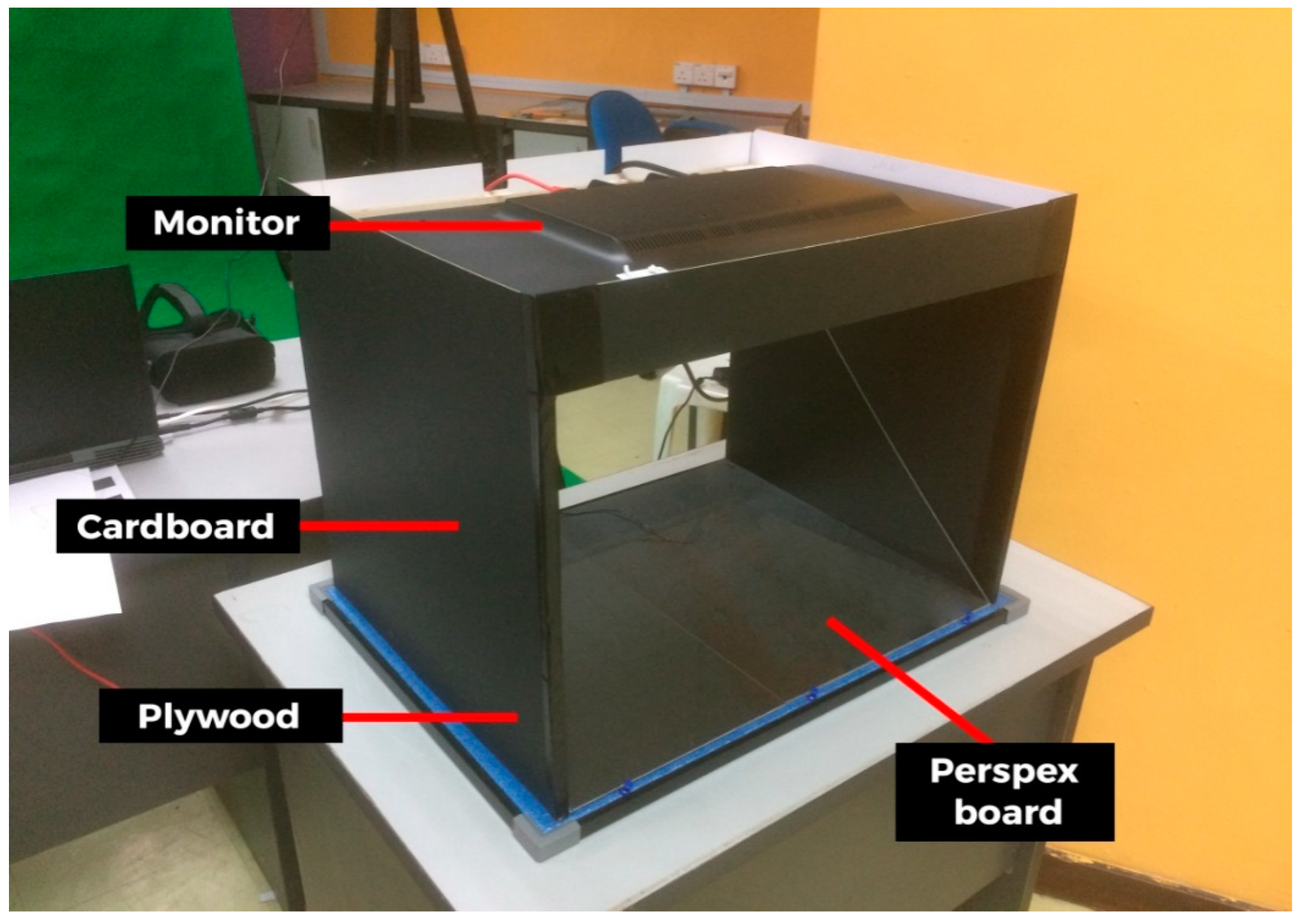
The Z-hologram is built with several components: a monitor screen, Perspex board, PVC pipe, and plywood. Firstly, the hologram is built with the Perspex board according to the measurement of the monitor screen such that the holographic content fits onto the Perspex board. The monitor then projects the reconstructed user onto the Perspex board. The reconstructed user appeared in the real environment when the projection from the monitor was reflected on the Perspex. The Plywood board is used to support the monitor placed on the board such that the monitor is stable on the Perspex and acts as the wall structure for the hologram. The result is shown in
Figure 9.
A test application has been prepared to integrate the real-time 3D reconstruction with 3D telepresence. First, both local and remote users are required to set roles as either sender or receiver using the simple user interface (UI) of the application.
As explained in the previous section, the research framework has a few phases, including 3D reconstruction and 3D telepresence. The results for each process of the 3D reconstruction using the marching cube algorithm to a produced textured 3D model of the local user are as illustrated in
Figure 10. The first stage generates depth streams during data acquisition from the RGB-D sensor. Data acquisition was capturing and processing data input from each of the RGB-D cameras on the client site. The captured data will later be transmitted to the server using a stable network with background removal. During point cloud extraction, the data is captured from multiple sensors. After projecting from depth field to point cloud, a virtual scene is reconstructed from a sequence of point clouds. This process is called point cloud registration, where the algorithm has been used to estimate the rigid transformation between the two datasets of point clouds, which can then be used to merge the two sources of point clouds. This registration process can then extract objects and transform the point cloud data into surface information to recreate a 3D mesh. Up to the surface generation stage, we have confirmed that the application was still running in real-time.
Based on
Figure 10, the background removal has been using a depth map, and the foreground pixels were extracted when the foreground or background information was converted into binary ones and zeros, respectively. The corresponding point set estimation algorithm fused the point cloud projected using the filtered depth map captured from the RGB-D sensor. During surface generation using the Marching Cube algorithm, the voxel grid used was set to the size of the depth frame height and width before re-evaluating the grid, calculating each square to find acceptable triangles to generate the surface. Then, the attempt to create the calculated texture map was initiated for the texture mapping process. In
Table 1 we have presented the processing time measurement for the real-time process except for UV mapping.
Table 1 shows the results we have compared to previous research. Our method used two Kinects, although we aim to reduce the number of Kinects; later, we measured the processing times, fps and the number of triangles. The fps rate is highest and the processing time is faster. Next, we performed the integration process by sending the data over the network.
Based on
Table 1, our method used two Kinects compared to five Kinects, and the average numbers of triangles is significantly different. Our processing rate in frames per second produced higher than 78 fps compared to Alexiadis et al.’s [
30] findings. After the 3D-textured model of the local user has been reconstructed, the 3D data such as mesh and texture along with the audio of the local user will be compressed and transmitted across the network to the remote site after being assembled in a UDP packet. When the packet is received in the remote client site, the packet will be disassembled and the data will be decompressed before being displayed on the remote user’s PC. The experiment will not use green screen settings as it did in the present case [
34] in order to ensure that the device is used in practical situations of natural environments.
Figure 11 shows the results of the 3D telepresence where a remote user can view and interact with a reconstructed 3D textured model of a local user sent to the remote location over the network. We have tested displaying the reconstructed 3D textured model using a small-scale Z-hologram. Our method has been loaded into the telepresence system to present the 3D presence of user representation in real-time, and we compare our results with Cordova-Esparza [
13], whose work has performed real-time 3D reconstruction and was loaded into telepresence, and who also recorded their findings after the compression process in a color image, UV and compression data from client to server. We also performed the same process and recorded our findings.
Table 2 shows the comparison; based on compression from raw data to final data, there are significant differences, especially when we requested that the server perform the telepresence and communicate with client user. However, the texture mapping required an improvement in real-time. With UV mapping compression we cannot compare with Cordova-Esparza [
13], as they have not covered the UV compression in their method. However, we still present our UV compression results in
Table 2.
5. Conclusions
Over the years, people have tried to advance the development of 3D reconstruction with different innovations and technologies such as telepresence. This paper presents the marching cube algorithm in a real-time 3D reconstruction and integrates it with 3D telepresence technology. Firstly, this paper introduced 3D reconstruction for the telepresence system and discussed a few related works. Each process in the 3D reconstruction, which includes the data acquisition, the removing of the background, and the extracting of the point cloud, which was then used later to generate the surface and applied texture mapping of the local user in real-time, has been explained in this paper. The study also presented an application to implement the proposed method and framework. The application used to test our 3D reconstruction to run real-time in holographic display. The process explained in this article has shown that the 3D reconstruction of a user can be generated using commodity RGB-D cameras integrated with a telepresence system which can benefit the remote user when the 3D representation of the local user is displayed in the Z-hologram, which can be perceived in 3D.
In conclusion, in this paper we have examined the flow of the 3D reconstruction method. The method involved several processes, which include the capturing and data acquisition from the depth sensor, the background removal, and the point cloud extraction. The surface generation process using the Marching Cube algorithm has been explained in this paper before the process ended with texture mapping. Based on the results, the real-time 3D reconstruction that employed the marching cube algorithm to generate 3D human representation has been successfully merged with the telepresence system and displayed at the remote location. However, the communication cues and flow have not yet been covered in this paper. For future works we plan on extending our work using holographic projection using a projector-based device to display the resulting 3D reconstruction output to emphasize the 3D telepresence more. We also plan to perform an evaluation to measure the accuracy and the quality of point cloud data. The results regarding the network requirements such as the delay would be areas of our future investigation. Therefore, we conclude that this paper has presented 3D telepresence with communication features by using a holographic projection as a display. As highlighted in this paper, the processes in producing the real-time 3D reconstruction consists of data acquisition, background removal, point cloud extraction, and surface generation which applies a Marching Cube algorithm as a final output.


 ,
, 


