Article

Aerodynamic Shape Optimization of an Arc-Plate-Shaped Bluff Body via Surrogate Modeling for Wind Energy Harvesting

1
Engineering Research Center of Urban Disasters Prevention and Fire Rescue Technology of Hubei Province, School of Civil Engineering, Wuhan University, Wuhan 430072, China
2
School of Civil and Environmental Engineering, Harbin Institute of Technology, Shenzhen 518055, China
*
Author to whom correspondence should be addressed.
Appl. Sci. 2022, 12(8), 3965; https://doi.org/10.3390/app12083965
Submission received: 21 February 2022 / Revised: 10 April 2022 / Accepted: 12 April 2022 / Published: 14 April 2022
(This article belongs to the Special Issue New Advances in Fluid Structure Interaction)

Abstract

:
Galloping-based piezoelectric wind energy harvesters (WEHs) are being used to supply renewable electricity for self-powered devices. This paper investigates the performance of a galloping-based piezoelectric WEH, with different arc-plate-shaped bluff bodies to improve harvesting efficiency. The Latin hypercube sampling method was employed to design the experiment. After conducting a series of wind tunnel tests, a Kriging surrogate model was then established, with high accuracy. The results show that the wind energy harvester with an arc angle 0.40π and tail length 1.26D generated the maximum power. The output power of the proposed WEH was doubled by optimizing the aerodynamic shape of the bluff body. The reasons for the improvement are discussed in detail. The force measurement results indicated that a large value of the transverse force coefficient means a large galloping response of the WEH. The aerodynamic optimization of this study can be applied to improve the performance of galloping-based wind energy harvesters.

1. Introduction

Piezoelectric energy harvesters have attracted substantial attention in the last decades. Energy harvesters can generate sustainable power and, hence, are promising as an alternative to batteries, which have a limited life span, while requiring costly maintenance [1,2]. Piezoelectric energy harvesters, therefore, can be an excellent power source for self-powered devices, such as MEMS (microelectromechanical systems) and WSNs (wireless sensor networks). Among the different vibration-based energy resources, wind flow has been suggested as one of the most reliable energy resources, since the wind-induced vibrations of bluff bodies can have considerable amplitudes [3,4]. Consequently, piezoelectric energy harvesters based on wind-induced vibrations of bluff bodies can produce considerable electric energy. Wind-induced vibrations commonly utilized in piezoelectric wind energy harvesters (WEHs) include vortex-induced vibration (VIV) [5,6], galloping [7,8,9,10], flutter [11,12,13,14], and mixed aerodynamic phenomena [15,16,17]. Several comprehensive reviews on harnessing energy from wind flow have been published recently [18,19,20,21,22,23,24].
Various mathematical methods have been employed to promote harvesting performance [24]. For instance, Abdelkefi et al. [25] developed a coupled model of galloping-based WEH. Their results showed that the electrical load resistance and the Reynolds number play an essential role in determining the level of the harvested power and the onset wind velocity of galloping. Zhao et al. [26] compared the lumped variable model with the distributed variable model. The effects of load resistance, wind exposure area of the bluff body, mass of the bluff body, and length of the piezoelectric sheets on the power output were investigated. Tan et al. [27] solved electromechanical coupled distributed variable equations and theoretically examined the effects of electrical damping and mechanical damping on the performance of the WEH. The parameters were optimized based on mathematical methods for improving the performance of a WEH.
The mathematical models indicate that the geometric shape of the bluff body is one of the critical parameters determining the wind force on the WEH and governing the performance of the WEH [28,29]. Yang et al. [30] compared the effects of bluff bodies with different sections on the performance of a galloping-based WEH. The performance of square, rectangular, triangular, and D-shaped galloping-based WEHs was evaluated through experiments and analytical models. The test results showed that the square section had the lowest onset wind velocity of 2.5 m/s and the highest wind energy power of 8.4 mW. Kluger et al. [31] evaluated the effects of geometric shape and size of the tip body of a transversely galloping-based WEH, experimentally and theoretically. The results showed that the optimal combinations of lateral aerodynamic force coefficients minimized the critical wind velocity for instability and increased the amplitude. Abdelkefi et al. [32] investigated the effects of section geometry, resistance, and wind speed on an energy harvester. The results showed that the section geometry greatly influenced the initial galloping wind velocity. However, the efficiencies of WEHs were limited by the typical bluff body.
Aerodynamic shape optimization is an effective and simple method to improve the efficiency of a WEH. Hu, Tse, and Kwok [7] fitted fins to various corners of a square prism to form the kinetic energy source of a galloping-based piezoelectric energy harvester. They found that attaching fins to the leading corners improved the efficiency of the energy harvester by up to 2.5 times. Hu et al. [33] and Hu et al. [34] investigated the WEH with two small-size rod-shaped attachments on the main circular cylinder. The harvester harnessed the wind energy beyond the defined onset wind velocity and could still work efficiently over the range of lock-in wind velocity. Song et al. [35] examined the effect of a splitter plate placed in the near wake of a circular cylinder on the performance of a piezoelectric WEH. The results showed that the harvester was able to maintain significant amplitude vibrations, even beyond the lock-in wind speed range, and, hence, the range of effective working wind speed was expanded. Alhadidi et al. [36] augmented the rear face of the square prism with Y-shaped fins of different lengths and fork angles. This modification reduced the rise time of the harvester by as much as 75% compared to the finless square prism.
The above aerodynamic shapes were optimized based on the typical cross-section. The bluff bodies were constructed according to research experience and galloping characteristics. A circular arc bluff body has been studied for applications such as a velocity threshold detector and passive stability control of an unmanned flying vehicle. A circular arc bluff body is also capable of producing galloping oscillation. Bot [37] reported and analyzed experimental results on the forces generated by a high-camber thin section with a curved plate, and made measurements of the flow field using particle image velocimetry. Variations of lift were related to changes in the topology of the flow field around the section. These results explained the flow around a high-camber thin section and provided a detailed benchmark database in a simple geometry for model validations. Bot et al. [38] tested arc bodies with different sections and analyzed the force crisis. Souppez et al. [39] tested three geometrically similar circular arcs over a range of Reynolds numbers, from 53,530 to 218,000. The force crisis and boundary layer were analyzed by force measurement and particle image velocimetry, similarly to the circular cylinder. Tucker Harvey et al. [40] investigated a curved arc bluff body WEH experimentally and theoretically. Based on the particle image velocimetry, the separation flow attached to the rear surface of the blade at the initial position, and then the flow pattern enhanced the galloping performance.
A circular arc bluff body is a blade-shaped bluff body with great energy harvesting performance. WEHs with a blade-shaped bluff body can achieve a much higher energy output than those with a square prism. Liu et al. [41] proposed and designed a three-blade bluff body for wind energy harvesting. Both numerical simulations and experiments confirmed that the three-blade structure could achieve a higher energy output than a square prism. Liu et al. [42] presented a fork-shaped bluff body to improve the harvesting efficiency at low wind speed. The results demonstrated that a piezoelectric WEH with a fork-shaped structure could generate much higher output voltages than with the traditional bluff bodies, such as triangular prism and square prism.
From the above literature review, it is noted that the energy harvesting efficiency from the fluid flow is improved through the shape of the bluff body. For the shape of the bluff body, most research work focus on experimental trails, to compare different cross sections and, thus, enhance the energy harvesting. A rare work designed the shape of the bluff body from the perspective of fluid dynamics.
In the present study, an arc-plate-shaped bluff body is designed to improve the performance of a WEH. From a fluid dynamics point of view, the vortex reattachment decreases the lift force of the bluff body with a square cross-section. An arc-plate-shaped bluff body avoids the vortex reattachment and, thus, enhances the vibration. WEHs with arc-plate-shaped bluff bodies were tested in a wind tunnel. The Kriging surrogate model was established, accurately representing the mapping between the output power and the aerodynamic shape variables. The Kriging surrogate model is effective in shape optimization for discovering the change law and determining the optimal solution. The impacts of the shape modification on the efficiency of the WEH were evaluated. The transverse force coefficients of the arc-plate-shaped bluff body were acquired via force measurement tests in a wind tunnel. Based on the transverse force coefficients and quasi-steady theory, the observations in the wind energy harvesting tests were interpreted.

2. Characteristics and Optimization Objectives of a Galloping Bluff Body

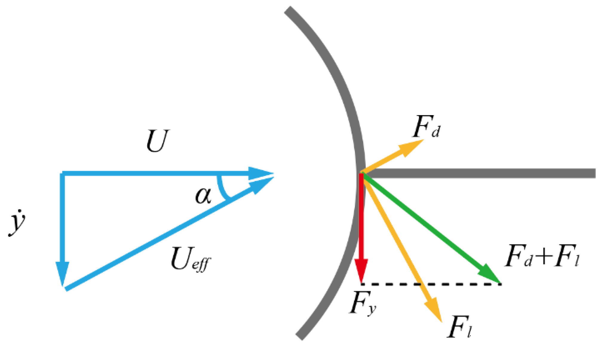
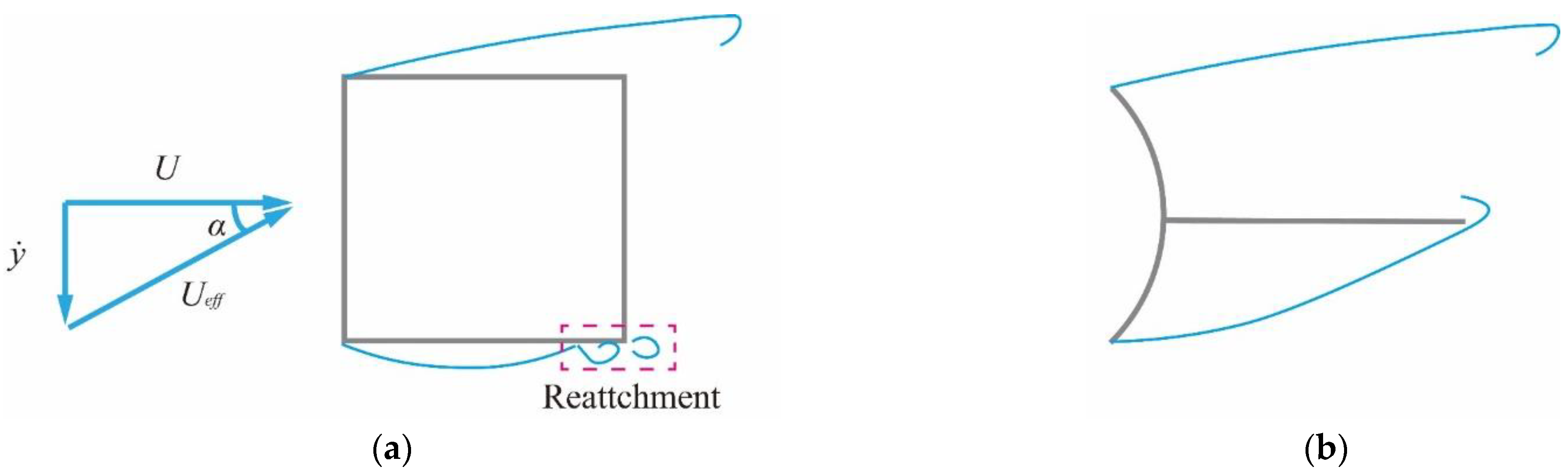
2.1. Characteristics of a Galloping Bluff Body

The aerodynamic shape of a galloping bluff body plays a dominant role in the efficiency of converting wind energy into vibration energy. The efficiency of energy harvesting can be improved significantly by optimizing the aerodynamic shape of the bluff body. The bluff body cross-sections of early galloping wind energy harvesters had typical bluff body sections, such as square, D-shape, or triangle [32]. Based on these typical sections, the cross-sections were modified for improving the efficiency of WEHs. Figure 1 shows cross-sections of a few optimized galloping bluff bodies.
In the process of the aerodynamic modification of the galloping bluff bodies, one optimization method is to add fins near the leading edge. The fins form sharp protrusions, resulting in stronger flow separation. A square prism with leading-edge fins [7] is shown in Figure 1a. Circular cylinders with different shape attachments [43,44] are shown in Figure 1b. A circular cylinder with roughness strips [45] is shown in Figure 1c.
Another optimization method is to add a plate near the trailing edge. Adding a plate increases the depth of the bluff body, resulting in increasing cross-wind force. A square prism with a Y-shaped plate near the trailing edge [36] is shown in Figure 1d. A circular cylinder with a splitter plate [35] is shown in Figure 1e.
In summary, the optimized aerodynamic shape of a galloping bluff body has the characteristics of a wide windward surface with sharp protrusions, and overall lengthening with a plate at the tail. As shown in Figure 1f, the blade bluff body has the characteristics of the optimized shape, and, hence, a blade-shaped bluff body has excellent galloping performance [40,46].
In order to systematically investigate the performance of the blade bluff body, an arc-plate bluff body, consisting of an arc and a plate at the tail, is proposed, as shown in Figure 2. The windward width D of the different bluff bodies is identical. The geometry of the arc-plate-shaped bluff body is described by two variables, a1 and a2, ranging from 0 to 1. The arc angle β = 2πa1, and the tail plate length Lt = 2Da2. Changing the two variables can create a variety of different shapes. For instance, when the arc angle β is 2π and the plate length Lt is 0, the bluff body is a circular cylinder; when the arc angle β is 2π and the plate length Lt is not 0, the bluff body is a circular cylinder with a plate, following the aerodynamic shape studied by Song, Hu, Tse, Li, and Kwok [35]. When the angle β is π/2 and the plate length Lt is 0, the bluff body follows the aerodynamic shape studied by Tucker Harvey, Khovanov, and Denissenko [40]. Therefore, the proposed arc-plate bluff body has a good ability to create a variety of aerodynamic shapes using two variables.

2.2. Optimization Objectives of a Galloping Bluff Body

The purpose of the shape optimization is to modify the design variables of the shape, to attain the optimal shape with the best potential performance, while satisfying certain constraints. After describing the design variables in terms of a set of n variables collected in the vector of the design variables x, the general optimization problem can be expressed as follows:
max   y ( x ) = [ f 1 ( x ) , f 2 ( x ) , , f p ( x ) ] T w . r . t .   x l x   x u   s . t . { h i ( x ) = 0 i = 1 , 2 , , n h g j ( x )     0 j = 1 , 2 , , n g
where y(x) is the p purpose objective function. xl and xu are design variables’ upper and lower limits, respectively. hi(x) and gj(x) are equality and inequality constraints, respectively. nh and ng are the number of constraints, respectively.
The mathematical expression for the aerodynamic shape optimization of the arc-plate bluff body is described as
find x = ( a 1 , a 2 ) max P e ( x ) w . r . t . x l x   x u s . t . h 1 ( x ) = D
where P(x)is the output energy of the galloping-based WEH with the shape of x.
It is well acknowledged that the output power varies with wind velocity. As a result, the performance of the WEH is assessed by an average output energy Pe weighted by the probability density distribution function of wind speed as
P e = U l U u P ( U ) f p ( U ) d U
where P(U) is the output power for a specific wind velocity U, fp (U) is the probability density distribution function of wind velocity, and UU and UL are the upper and lower limits of the wind speed, respectively. In this paper, the probability density distribution function of wind velocity fp is assumed as an uniform distribution in the tested wind velocity range, i.e.,
f p ( U ) = 1 U U U L , U L U U U

3. Surrogate Modeling

3.1. The Kriging Surrogate Modeling Method

Shape optimization is necessary and important in engineering, such as vehicle shapes, airfoil shapes, and building shapes. Surrogate-based optimization has been shown to be a practical approach in aeronautics and astronautics engineering [47,48], civil engineering [49,50], and ocean engineering [51,52]. The surrogate model can replace many expensive objective evaluations with an approximation model. Wang and Shan [53] provided an overview of surrogate models, focusing on solving optimization problems such as global optimization, multi-objective optimization, and probabilistic design optimization. Forrester and Keane [54] discussed details of surrogate modeling methodology, focusing on sampling, surrogate model building, and validation. Westermann and Evins [55] explained the use of surrogate modeling for building design regarding applications in the conceptual design stage, sensitivity and uncertainty analysis, and building design optimization.
Many surrogate models have been adopted in the field of optimization, such as polynomial regression, radial basis functions, neural networks, and support vector regression [56]. In the present work, the widely used Kriging model was adopted [49].
For a stationary random process, the statistical prediction of the unknown function y at an untried x is given by a linear combination of the function values at the original samples and their gradients at observed points, as follows:
y ^ ( x ) = i = 1 n w ( i ) y ( i )
where y ^ ( x ) is the predicted value at an untried site x, w ( i ) is the weight coefficient for the function value y ( i ) . To determine the weight coefficient, the output of a deterministic experiment is treated as a realization of a stochastic process, i.e.,
Y ( x ) = β 0 + Z ( x )
where β 0 is an unknown constant mean value and the stationary random processes Z ( x ) having zero mean and a covariance Cov,
Cov [ Z ( x ) , Z ( x ) ] = σ 2 R ( x , x )
where σ 2 is the process variance of Z ( x ) , R is the spatial correlation function, which depends only on the spatial distance between two sites. y ^ ( x ) is treated as random, and we try to minimize its mean squared error (MSE)
MSE [ y ^ ( x ) ] = E [ ( w T Y S Y ( x ) ) 2 ]
subject to the unbiasedness constraint
E [ i = 1 n w ( i ) Y ( x ( i ) ) ] = E [ Y ( x ) ]
where Ys is the response of the sample points. Solving this constrained minimization problem, w ( i ) can be found by solving the following linear equations in matrix form:
[ R F F T 0 ] [ w μ ˜ ] = [ r 1 ]
where
F = [ 1 1 1 ] T n
μ ˜ = μ / ( 2 σ 2 )
R = [ R ( x ( 1 ) , x ( 1 ) ) R ( x ( 1 ) , x ( n ) ) R ( x ( n ) , x ( 1 ) ) R ( x ( n ) , x ( n ) ) ] n × n
r = [ R ( x ( 1 ) , x ) R ( x ( n ) , x ) ] n
where R is the correlation matrix representing the correlation between the observed points, and r is the correlation vector representing the correlation between the untried point and the observed points. The kriging predictor can be written in the form
y ^ ( x ) = β 0 + r T ( x ) R 1 ( y S β 0 F )
where β 0 = ( F T R 1 F ) 1 F T R 1 y S .

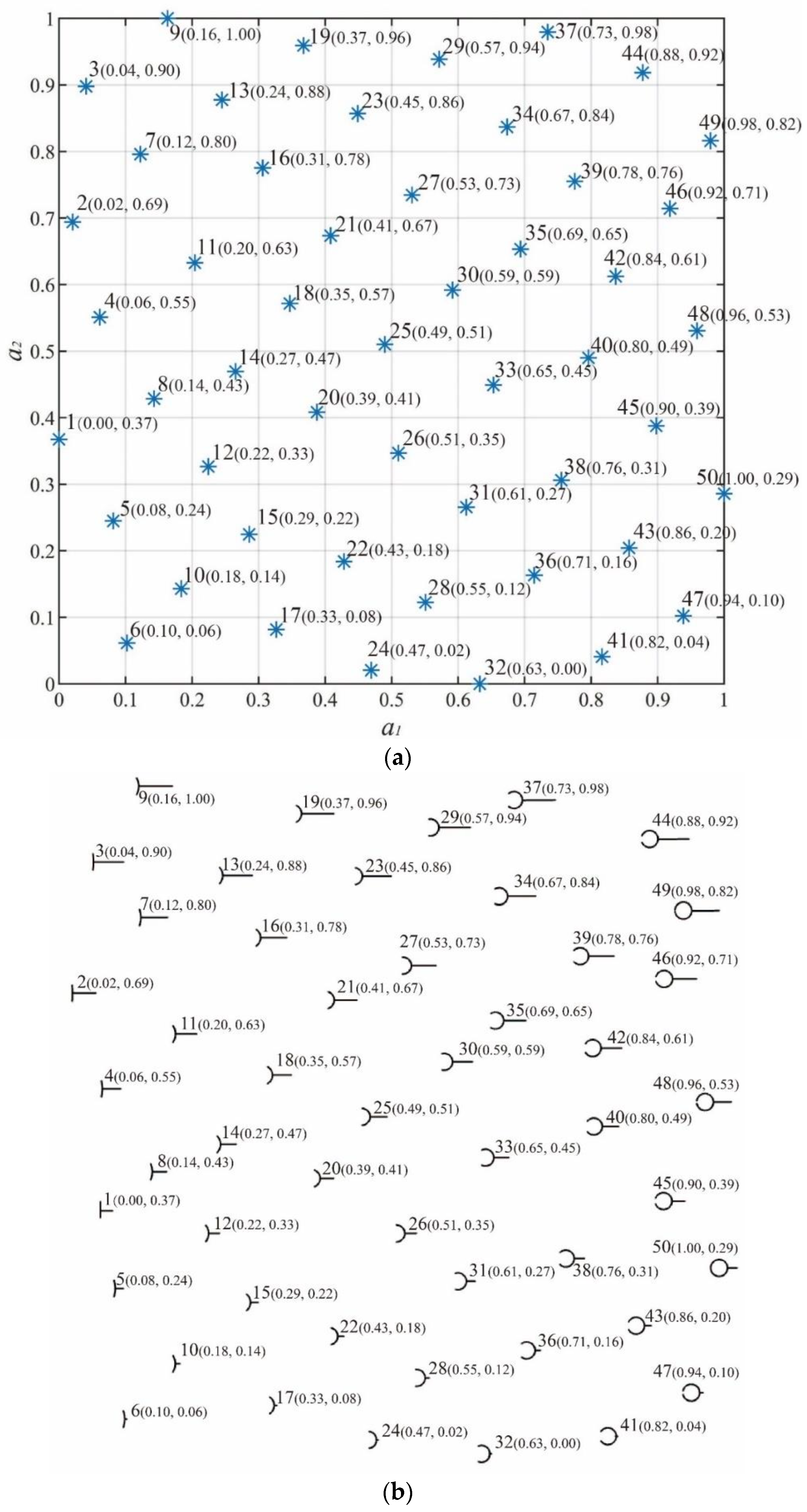
3.2. Design of Experiments
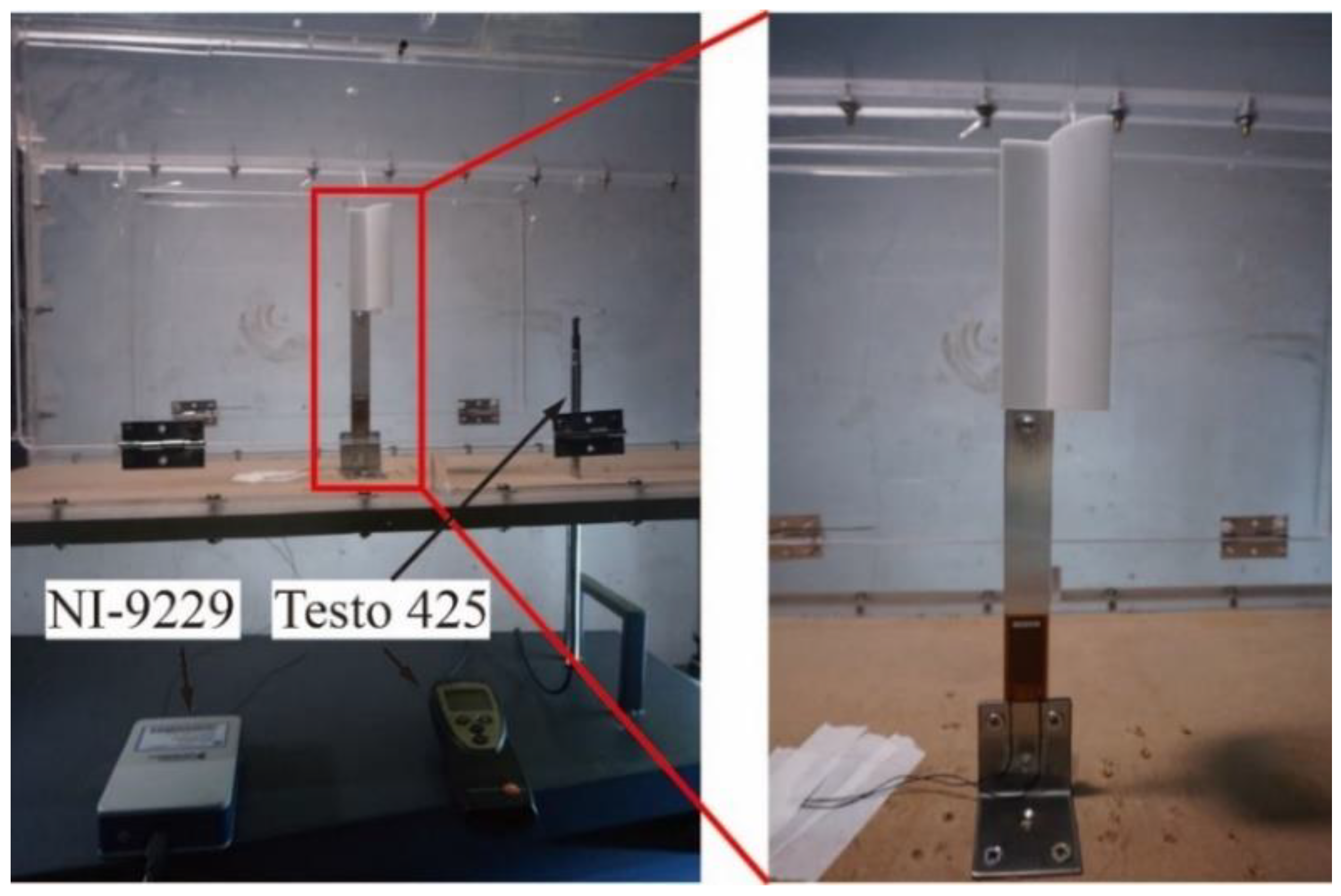
The purpose of conducting the design of experiments is to generate sampling points for the surrogate model. Since we have no prior knowledge about how the objective output functions vary over the input space, the principle of a sampling plan is to fill the design space with sampling points, as uniformly as possible. For this purpose, a space-filling strategy named Latin hypercube sampling (LHS) for uniform random sampling was employed. The LHS can avoid the over-concentration of the sampled points in a small range and make the sample points evenly distributed in the sampling area. For sampling ns sample points, nv design variables are evenly divided into nsl intervals. The total sampling interval is divided into ( n v ) n s subintervals. When each sample point is projected into any dimension, there is only one sample point in each interval.
In the aerodynamic shape optimization of the arc-plate bluff body, 50 sample points were taken for the control variables a1 and a2 in the range from 0 to 1. As shown in Figure 3a, 50 samples for the modeling were generated in the two-dimensional input space. The shapes of bluff bodies are shown in Figure 3b, corresponding to all the sample points. Taking shape 2 as an example, a1 = 0.02 and a2 = 0.69, the angle of arc β is 0.04π, and the plate length Lt is 0.69D. The corresponding bluff body section is approximately T-shaped. For shape 47, where a1 = 0.94 and a2 = 0.10, arc angle β is 1.88π and the plate length Lt is 0.20D. The related bluff body section is roughly circular. For shape 49, where a1 = 0.98 and a2 = 0.82, arc angle β is 1.96π and the plate length Lt is 1.64D. The resultant bluff body section follows the aerodynamic shape studied by Song, Hu, Tse, Li, and Kwok [35]. It can be concluded that the arc-plate bluff body controlled by two variables can describe a variety of aerodynamic shapes using LHS.

4. Wind Tunnel Test

4.1. Piezoelectric Wind Energy Harvesting Tests

The wind tunnel tests in this study were conducted in the open-circuit wind tunnel at Wuhan University, as shown in Figure 4. The wind tunnel has a 40 cm × 40 cm test cross-section and a low-turbulence flow, with a less than 1.5% turbulence intensity. The aluminum cantilever beam’s length, width, and thickness were 12, 1.8, and 0.1 cm, respectively. The bluff body was produced with 3D printing technology, with a height of 10 cm and a width D of 5 cm. The piezoelectric layer (MFC-2814P2, Smart Material Corp, Sarasota, FL, USA) was connected to the electrical load resistances R. The voltage V across the load resistance was measured using a DAQ module (NI-9229, National Instruments, Austin, TX, USA). The wind velocity U of the incoming flow was measured using an anemometer (Testo 425, Testo SE & Co., Titisee-Neustadt, Germany).
The natural frequency and damping ratio were 8.65 Hz and 1.2%, which was determined using a free vibration test. The effective mass and stiffness were 27.7 g and 81.8 N/m, which were lumped by a distributed model [57]. The tested wind speeds ranged from 0.5 m/s to 7 m/s, with an interval of 0.5 m/s. Accordingly, the Reynolds number ranged from 1.7 × 10³ to 2.4 × 10⁴.

4.2. Force Measurement Tests

A series of force measurement tests were performed on the arc-plate-shaped bluff body in the wind tunnel, to examine the global aerodynamic characteristics, as shown in Figure 5. The bluff body was mounted on a six-dimensional force balance (Gamma, ATI industrial automation, Apex, NC, USA), to measure wind forces on the body. A servo motor determined the rotation angle of the body, simulating different directions of oncoming wind flow.

4.3. Uncertainty Analyses

Experimental results always contain errors, so uncertainty should also be analyzed. The wind velocity U of the incoming flow was measured using an anemometer (Testo 425, Testo SE & Co., Titisee-Neustadt, Germany). The range of velocity measurement was from 0 to 20 m/s. The resolution of the anemometer was 0.01 m/s. The accuracy of the anemometer was ±(0.03 m/s + 5% of measured values). The bluff body was produced with a 3D printer (Form 3 L, Formlabs Corp, Somerville, MA, USA), with a resolution of 0.025 mm. The accuracy of the bluff body’s width and length were ±1.2 mm and ±0.2 mm, respectively, because the bluff bodies were thin-walled structures, prone to temperature strain. The force was measured using a six-dimensional force balance (Gamma, ATI industrial automation, Apex, NC, USA). The resolution of the force balance was 0.00625 N. The accuracy of the force balance was ±1%. The resolution of the wind direction was 0.017°. The accuracy of the wind direction was ±0.036°. The resolution of the electric resistance was 1000 Ω, and the accuracy is 1%. The voltage across the load resistance was measured with a DAQ module (NI-9229, National Instruments, Austin, TX, USA). The resolution of the voltage DAQ module was 3.6 × 10⁻⁶ V. The accuracy of the voltage DAQ module was ±0.03% of the measured value. The accuracy and resolution of the measuring instruments and equipment are shown in Table 1.
The average output power of the wind energy harvester was computed using the associated voltage as P = V r m s 2 / R , where Vrms is the root mean square of the voltage. The uncertainty was assessed using the Taylor series method (TSM) [58]. The correlated random error terms were assumed to be zero. The standard uncertainty of average output power P is expressed as
s P = 4 s V 2 + s R 2
where SV and SR are standard uncertainties of voltage and resistance, respectively. The random uncertainty values for output power P is ±1.0%.
The transverse force coefficient CFy is expressed as
C F y = F y 1 2 ρ a U 2 B L
where ρ a is the air density, B and L are the width and length of the bluff body, and U is wind velocity.
The errors in the values of the variables on the right-hand side of Equation (17) will cause errors in the experimental result CFy. The uncertainty was calculated using the Taylor series method (TSM) [58]. It was assumed that only U, B, L, and Fy contributed to the random uncertainty. These correlated random error terms were assumed to be zero. The standard uncertainty of force coefficient is expressed as
s C F y = 4 s u 2 + s F y 2 + s B 2 + s L 2
where Su, SFy, SB, and SL are standard uncertainties of the wind velocity, force, width, and length of the bluff body. The random uncertainty values for CFy using the TSM are shown in Table 2. The standard uncertainty of force coefficient was caused by the error of the anemometer. The accuracy of the anemometer was ±(0.03 m/s + 5% of measured value), and the force was proportional to the square of the wind velocity.

5. Results and Discussions

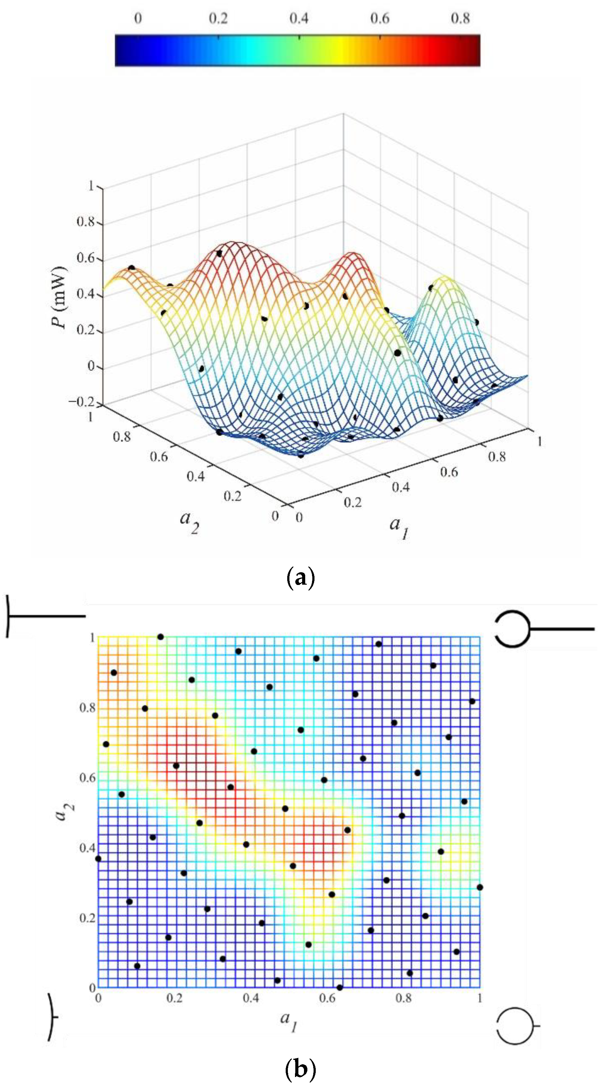
5.1. Surrogate Model

Based on the wind tunnel test results, the Kriging model was constructed for the average output power, as shown in the three-dimensional and two-dimensional cartesian coordinates in Figure 6. The response surface fit well with the sampling points. The variation of the average output power with the aerodynamic shape variables can be observed intuitively. For the two-variable optimization problem, 50 sample points were enough to establish a surrogate model with high accuracy. For instance, Bernardini, Spence, Wei, and Kareem [49] constructed an ordinary Kriging using 90 samples. Ding and Kareem [50] constructed a multi-fidelity Kriging model with 50 samples for a two-variable aerodynamic shape optimization of civil structures.
According to the experimental results, the average output power of the WEH with shape 11 was maximum for the variables a1 = 0.20 and a2 = 0.63. The arc angle β and tail length Lt were 0.40π and 1.26D, respectively. The WEH with shape 18 had an excellent performance when a1 = 0.35 and a2 = 0.57. The arc angle β and tail length Lt were 0.70π and 1.14D, respectively. The surrogate model had a peak region for the average output power Pe, as in the red colored area with an inclination of 45° shown in Figure 6. The WEHs corresponding to the peak region output have abundant power because the bluff body of the WEHs is prone to gallop. For the other areas in Figure 6, the output power declines rapidly and decays to zero. Based on the surrogate model, the impacts of the shape modification on the efficiency of the WEH are further evaluated in the subsequent sections.

5.2. Output Power

In order to investigate effect of the bluff body’s shape on the output power, the variation of output power with wind velocity for WEHs with different arc angle bluff bodies is shown in Figure 7. The tail length of the bluff body is almost identical. The WEH starts to work at a wind velocity of 2 m/s. The output power increases with the increase of the wind velocity. The bluff body with shape 18 had the most significant output power. The max output power was 2 mW at a wind velocity of 7 m/s. For the bluff body with a large arc angle, such as shapes 30 and 42, the output power was far lower than that of shape 18, and the max output power was only 0.5 mW at 7 m/s. It can be concluded that the output power tends to decrease with the increase of the arc angle of the bluff body.
The variation of output power with wind velocity for WEHs with different tail length bluff bodies is shown in Figure 8. As can be seen, the tail length of shape 18 was between those of shapes 17 and 19. However, the output power of the WEH with shape 18 was the maximum. The WEH with shape 17 almost ceased to work. The output power of the WEH with shape 19 was minimal for all wind velocities and was only 0.5 mW at a wind velocity of 7 m/s. Compared with the WEH with too long and too short a tail length, an optimal tail length can provide the maximal output power.
The variation of output power with wind velocity for WEHs with prism and arc-plate-shaped bluff bodies is shown in Figure 9. The aerodynamic shapes of the arc-plate-shaped bluff bodies are within the region of the Kriging surrogate model showing the maximum output power. The WEHs with the prism- and arc-plate-shaped bluff bodies have considerable energy output. The critical galloping wind speeds of bluff bodies with different sections were all around 2 m/s. When the wind speed was 7 m/s, the output power of the WEH with shape 11 and the prism bluff body was 2.3 mW and 1.1 mW, respectively. Compared with the WEH with a prism bluff body, the output power of the WEH with shape 11 doubled, indicating the significance of optimization of the aerodynamic shape of the bluff body section. The aerodynamic optimization of this study can, therefore, be directly applied in piezoelectric WEHs, to increase power generation significantly.

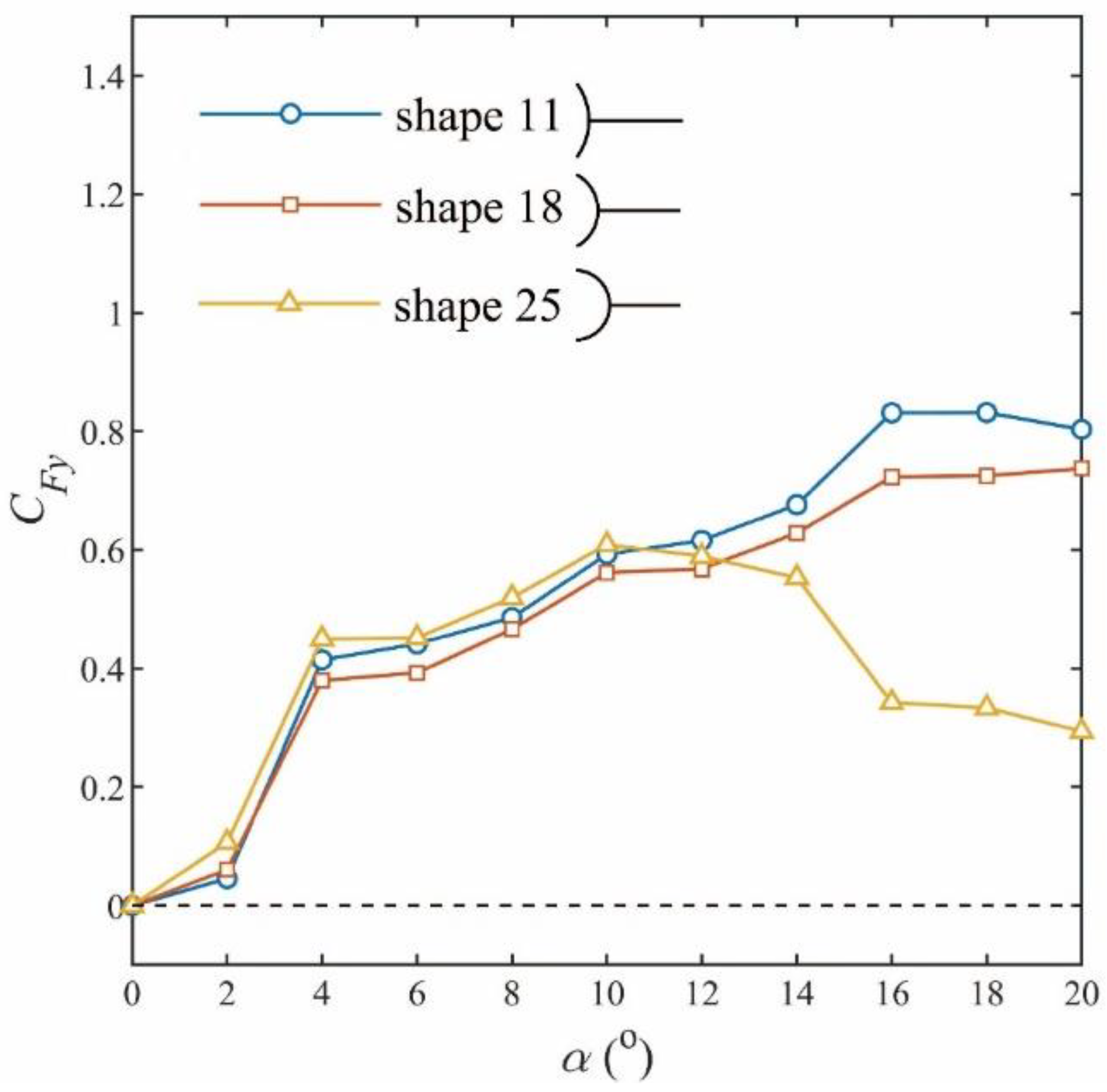
5.3. Force Coefficient

According to the quasi-steady theory by Parkinson [59,60], the drag force Fd and lift force Fl at each attack angle α in the process of oscillation are the same as the values measured at the corresponding steady attack angle α. The relative attack angle α = arctan(/U) and forces were defined, as shown in Figure 9. The transverse force is the resultant of both drag force Fd and lift force Fl
F y = F L cos α F D sin α
Transverse force Fy was directly measured in the wind tunnel using the force balance. The transverse force coefficient CFy is expressed as
C F y = F y 1 2 ρ a U e f f 2 A
where ρ a is the air density, A is the projected area of the bluff body, and Ueff is effective wind velocity.
The differential equation governing the galloping oscillation is
m y ¨ + C y ˙ + K y = F y = 1 2 C F y ρ a U e f f 2 A
where m, C, and K are the mass, damping, and stiffness modified by an electromechanical decoupled model [61]. The net damping ratio of the system is
d = C y ˙ 1 2 C F y ρ a U e f f 2 A
If d > 0, the system tends toward stability. When and CFy are in the same direction, as shown in Figure 10, the aerodynamic force is negative. Negative aerodynamic damping is an essential prerequisite for the galloping instability. With the increase of the wind velocity, d decreases gradually and may be negative, and then the system is prone to instability. In terms of the well-known Den Hartog criterion [62,63], the necessary condition for the occurrence of the galloping instability is C F y α | α = 0 ° > 0 . In other words, a positive slope of the CFy versus α curve at α = 0° is an essential prerequisite for galloping instability.
The variation of transverse force coefficient CFy with wind attack angle α for bluff bodies with different arc angles is shown in Figure 11. The slopes of the transverse force coefficient of all the three bluff bodies are positive when wind attack angle α = 0°. As a result, the corresponding WEHs work at high wind velocity, as shown in Figure 7. With the increase of the wind attack angle, the transverse force coefficient of shape 18 is much more significant than those of shapes 30 and 42. This is because the transverse force provides the negative aerodynamic force, and then the output power of the WEH with the shape 18 is much larger than those with the shapes 30 and 42.
The variation of transverse force coefficient CFy with wind attack angle α for bluff bodies with different tail lengths is shown in Figure 12. The slope of the transverse force coefficient of shape 17 is positive at α = 0°. In other words, shape 17 satisfies the essential prerequisite of galloping. The transverse force coefficient remains positive, but the value of the transverse force coefficient is relatively small, less than 0.1. The WEH with the shape 17 hardly works, because the bluff body cannot produce the aerodynamic damping force. The slope of the transverse force coefficient of shape 19 is positive at α = 0°. The bluff body also satisfies the essential prerequisite of galloping. The transverse force coefficient of shape 19 increased at the initial wind attack angle and decreased with the wind attack angle α > 6°. Although the WEH with the shape 19 can work, the performance was barely satisfactory.
The variation of transverse force coefficient CFy with wind attack angle α for bluff bodies with excellent vibration performance is shown in Figure 13, for different wind attack angles α. The selected bluff bodies are within the region of the surrogate model showing peak output energy. For the three bodies shown in Figure 13, the slopes of the transverse force coefficient CFy are all positive at α = 0. The transverse force coefficients of the bluff bodies increase rapidly with α. The transverse force coefficient of shape 25 is less than those of the other two when α ≥ 14°, and hence the output power of the WEH with the shape 25 bluff body outputs was less than those of the other two.
Based on the above discussion, it can be concluded that the performance of WEHs is highly associated with the transverse force coefficient of the bluff bodies. A large value of the transverse force coefficient usually means a large galloping response. Meanwhile, the above results verify the quasi-steady theory and indicate that the static wind tunnel test was accurate and reliable.

5.4. Comparision and Discussion

The performance of a wind energy harvester is mainly affected by the shape and mass of the bluff body, the material characteristics and dimensions of the cantilever beam, the characteristics of the piezoelectric transducer, the conditions of the approaching flow, etc. The harvesting efficiencies of various typical galloping experimental results are summarized in Table 3. The harvesting efficiencies were calculated according to the method from Bernitsas et al. [64]. It can be found that the efficiency of the No.1 harvester was much higher than that of this paper, because the bluff body was made from lightweight materials, with a mass of 1.8 g. The bluff body in the present research was produced by 3D printing technology, with a mass of 25 g. Three-dimensional printing technology was adopted as it replicates the shape more delicately for precise shape optimization. The power of the No.1, 2, and that in this work exceed 1 mW, which is able to power the Internet of Things (IoT) ViPSN platform for a vibration-powered sensing and transmitting system [65]. The efficiencies of No.3, 4, and 5 were much lower than that of this paper, because the characteristics of the piezoelectric transducer were poor.
The results of the harvesters with the square and arc-plate shaped bluff body were compared. The output power of the WEHs with a square and arc-plate-shaped bluff body was 0.50 mW and 1.01 mW at wind velocity of 5 m/s. Meanwhile, the efficiency was improved from 0.12% to 0.25%. For a wind velocity of 7 m/s, the output power was enhanced from 1.12 mW to 2.31 mW, and the efficiency was improved from 0.10% to 0.21%. The aerodynamic shape optimization doubled both the output power and efficiency
For the square cross-section, the vortex reattachment phenomenon often appears near the side faces, as shown in Figure 14a. This phenomenon causes up-side and down-side pressure fluctuations and, thus, reduces the total lift force of the bluff body [68]. Fortunately, the arc-plate-shaped bluff body avoids the vortex reattachment and, thus, guarantees the coordination of vortex shedding, as shown in Figure 14b. Therefore, the lift force of the arc-plate-shaped cross-section is larger than that of the square cross-section.
The above comparison demonstrates the superiority of the aerodynamic shape optimization of an arc-plate-shaped bluff body. This finding has great potential to be applied in energy harvesters based on galloping. In the past few years, significant efforts have been made to develop various types of piezoelectric energy harvesters based on wind-induced vibrations as the power source for wireless sensors. The work of this study can be directly applied to this type of piezoelectric wind energy harvester, to increase the power generation significantly.
Bernitsas’s team [64] invented a device converting ocean/river current’s hydrokinetic energy to electricity using a circular bluff body. Different-shaped bluff bodies were also investigated for energy harvesting, such as prism-, triangular-, and pentagon-shaped bluff bodies [69,70]. Although this converter was driven by ocean/river currents, the findings achieved with wind flow reported in the current study are potentially applicable.

6. Conclusions

In this paper, the aerodynamic shape of a arc-plate bluff body was optimized, based on the output energy of a galloping-based WEH. The Latin hypercube sampling method was employed for the design of the experiment. According to the wind tunnel test results, a Kriging surrogate model with a high accuracy was established. The variation of transverse force coefficients of the bluff body with wind attack angle was examined in detail. Experiments were employed to prove the superiority of the arc-plate-shaped bluff body for energy harvesting. The following conclusions were obtained.
(a) Through the Latin hypercube sampling method, the arc-plate shape determined by the two variables can describe a variety of aerodynamic shapes. The Kriging surrogate model established by the wind tunnel test showed a high degree of fit with the sampling points, which laid the foundation for the subsequent shape modification.
(b) The output power of the WEH was significantly increased by optimizing the aerodynamic shape. The WEH with the arc angle 0.40π and tail length 1.26D generated the maximum power.
(c) The output power of the WEH was related to the transverse force coefficient. A large transverse force coefficient usually means a large output power of a galloping-based WEH.
(d) Optimizing the aerodynamic shape of the bluff body section doubled the output power of the WEH, compared with the WEH with a prism bluff body.

Author Contributions

Conceptualization, G.H.; methodology, formal analysis, and investigation, T.S.; writing—original draft preparation, T.S.; writing—review and editing, L.Z.; supervision, L.Z.; project administration, L.Z.; funding acquisition, L.Z. All authors have read and agreed to the published version of the manuscript.

Funding

This study was funded by the National Natural Science Foundation of China, under project No. 51478369.

Institutional Review Board Statement

Not applicable.

Informed Consent Statement

Not applicable.

Data Availability Statement

Data sharing is not applicable.

Conflicts of Interest

The authors declare no conflict of interest.

References

  1. Shaikh, F.K.; Zeadally, S. Energy harvesting in wireless sensor networks: A comprehensive review. Renew. Sustain. Energy Rev. 2016, 55, 1041–1054. [Google Scholar] [CrossRef]
  2. Alaei, E.; Afrasiab, H.; Dardel, M. Analytical and numerical fluid–structure interaction study of a microscale piezoelectric wind energy harvester. Wind Energy 2020, 23, 1444–1460. [Google Scholar] [CrossRef]
  3. Larsen, A. A generalized model for assessment of vortex-induced vibrations of flexible structures. J. Wind Eng. Ind. Aerodyn. 1995, 57, 281–294. [Google Scholar] [CrossRef]
  4. Arunachalam, S.; Lakshmanan, N. Across-wind response of tall circular chimneys to vortex shedding. J. Wind Eng. Ind. Aerodyn. 2015, 145, 187–195. [Google Scholar] [CrossRef]
  5. Abdelkefi, A.; Hajj, M.R.; Nayfeh, A.H. Phenomena and modeling of piezoelectric energy harvesting from freely oscillating cylinders. Nonlinear Dyn. 2012, 70, 1377–1388. [Google Scholar] [CrossRef]
  6. Dai, H.; Abdelkefi, A.; Wang, L. Theoretical modeling and nonlinear analysis of piezoelectric energy harvesting from vortex-induced vibrations. J. Intell. Mater. Syst. Struct. 2014, 25, 1861–1874. [Google Scholar] [CrossRef]
  7. Hu, G.; Tse, K.T.; Kwok, K.C.S. Enhanced performance of wind energy harvester by aerodynamic treatment of a square prism. Appl. Phys. Lett. 2016, 108, 123901. [Google Scholar] [CrossRef]
  8. Hu, G.; Wang, J.; Su, Z.; Li, G.; Peng, H.; Kwok, K.C.S. Performance evaluation of twin piezoelectric wind energy harvesters under mutual interference. Appl. Phys. Lett. 2019, 115, 073901. [Google Scholar] [CrossRef]
  9. Javed, U.; Abdelkefi, A. Role of the galloping force and moment of inertia of inclined square cylinders on the performance of hybrid galloping energy harvesters. Appl. Energy 2018, 231, 259–276. [Google Scholar] [CrossRef]
  10. Zhao, L.; Yang, Y. An impact-based broadband aeroelastic energy harvester for concurrent wind and base vibration energy harvesting. Appl. Energy 2018, 212, 233–243. [Google Scholar] [CrossRef]
  11. Abdelkefi, A.; Nayfeh, A.H.; Hajj, M.R. Enhancement of power harvesting from piezoaeroelastic systems. Nonlinear Dyn. 2012, 68, 531–541. [Google Scholar] [CrossRef]
  12. Orrego, S.; Shoele, K.; Ruas, A.; Doran, K.; Caggiano, B.; Mittal, R.; Kang, S.H. Harvesting ambient wind energy with an inverted piezoelectric flag. Appl. Energy 2017, 194, 212–222. [Google Scholar] [CrossRef]
  13. McCarthy, J.M.; Watkins, S.; Deivasigamani, A.; John, S.J.; Coman, F. An investigation of fluttering piezoelectric energy harvesters in off-axis and turbulent flows. J. Wind Eng. Ind. Aerodyn. 2015, 136, 101–113. [Google Scholar] [CrossRef]
  14. Doaré, O.; Michelin, S. Piezoelectric coupling in energy-harvesting fluttering flexible plates: Linear stability analysis and conversion efficiency. J. Fluids Struct. 2011, 27, 1357–1375. [Google Scholar] [CrossRef] [Green Version]
  15. Petrini, F.; Gkoumas, K. Piezoelectric energy harvesting from vortex shedding and galloping induced vibrations inside HVAC ducts. Energy Build. 2018, 158, 371–383. [Google Scholar] [CrossRef]
  16. Shan, X.; Tian, H.; Cao, H.; Xie, T. Enhancing Performance of a Piezoelectric Energy Harvester System for Concurrent Flutter and Vortex-Induced Vibration. Energies 2020, 13, 3101. [Google Scholar] [CrossRef]
  17. Yang, K.; Su, K.; Wang, J.; Wang, J.; Yin, K.; Litak, G. Piezoelectric wind energy harvesting subjected to the conjunction of vortex-induced vibration and galloping: Comprehensive parametric study and optimization. Smart Mater. Struct. 2020, 29, 075035. [Google Scholar] [CrossRef]
  18. Abdelkefi, A. Aeroelastic energy harvesting: A review. Int. J. Eng. Sci. 2016, 100, 112–135. [Google Scholar] [CrossRef]
  19. Li, D.; Wu, Y.; Da Ronch, A.; Xiang, J. Energy harvesting by means of flow-induced vibrations on aerospace vehicles. Prog. Aeosp. Sci. 2016, 86, 28–62. [Google Scholar] [CrossRef] [Green Version]
  20. Rostami, A.B.; Armandei, M. Renewable energy harvesting by vortex-induced motions: Review and benchmarking of technologies. Renew. Sustain. Energy Rev. 2017, 70, 193–214. [Google Scholar] [CrossRef]
  21. Wei, C.; Jing, X. A comprehensive review on vibration energy harvesting: Modelling and realization. Renew. Sustain. Energy Rev. 2017, 74, 1–18. [Google Scholar] [CrossRef]
  22. Zou, H.; Zhao, L.; Gao, Q.; Zuo, L.; Liu, F.; Tan, T.; Wei, K.; Zhang, W. Mechanical modulations for enhancing energy harvesting: Principles, methods and applications. Appl. Energy 2019, 255, 113871. [Google Scholar] [CrossRef]
  23. Watson, S.; Moro, A.; Reis, V.; Baniotopoulos, C.; Barth, S.; Bartoli, G.; Bauer, F.; Boelman, E.; Bosse, D.; Cherubini, A.; et al. Future emerging technologies in the wind power sector: A European perspective. Renew. Sustain. Energy Rev. 2019, 113, 109270. [Google Scholar] [CrossRef]
  24. Wang, J.; Geng, L.; Ding, L.; Zhu, H.; Yurchenko, D. The state-of-the-art review on energy harvesting from flow-induced vibrations. Appl. Energy 2020, 267, 114902. [Google Scholar] [CrossRef]
  25. Abdelkefi, A.; Hajj, M.R.; Nayfeh, A.H. Power harvesting from transverse galloping of square cylinder. Nonlinear Dyn. 2012, 70, 1355–1363. [Google Scholar] [CrossRef]
  26. Zhao, L.; Tang, L.; Yang, Y. Comparison of modeling methods and parametric study for a piezoelectric wind energy harvester. Smart Mater. Struct. 2013, 22, 125003. [Google Scholar] [CrossRef]
  27. Tan, T.; Yan, Z.; Lei, H. Optimization and performance comparison for galloping-based piezoelectric energy harvesters with alternating-current and direct-current interface circuits. Smart Mater. Struct. 2017, 26, 075007. [Google Scholar] [CrossRef]
  28. Bibo, A.; Daqaq, M.F. An analytical framework for the design and comparative analysis of galloping energy harvesters under quasi-steady aerodynamics. Smart Mater. Struct. 2015, 24, 094006. [Google Scholar] [CrossRef]
  29. Bibo, A.; Daqaq, M.F. On the optimal performance and universal design curves of galloping energy harvesters. Appl. Phys. Lett. 2014, 104, 023901. [Google Scholar] [CrossRef]
  30. Yang, Y.; Zhao, L.; Tang, L. Comparative study of tip cross-sections for efficient galloping energy harvesting. Appl. Phys. Lett. 2013, 102, 064105. [Google Scholar] [CrossRef]
  31. Kluger, J.M.; Moon, F.C.; Rand, R.H. Shape optimization of a blunt body Vibro-wind galloping oscillator. J. Fluids Struct. 2013, 40, 185–200. [Google Scholar] [CrossRef]
  32. Abdelkefi, A.; Yan, Z.; Hajj, M.R. Performance analysis of galloping-based piezoaeroelastic energy harvesters with different cross-section geometries. J. Intell. Mater. Syst. Struct. 2014, 25, 246–256. [Google Scholar] [CrossRef]
  33. Hu, G.; Tse, K.T.; Kwok, K.C.S.; Song, J.; Lyu, Y. Aerodynamic modification to a circular cylinder to enhance the piezoelectric wind energy harvesting. Appl. Phys. Lett. 2016, 109, 193902. [Google Scholar] [CrossRef]
  34. Hu, G.; Liu, F.; Li, L.; Li, C.; Xiao, Y.; Kwok, K.C.S. Wind energy harvesting performance of tandem circular cylinders with triangular protrusions. J. Fluids Struct. 2019, 91, 102780. [Google Scholar] [CrossRef]
  35. Song, J.; Hu, G.; Tse, K.T.; Li, S.W.; Kwok, K.C.S. Performance of a circular cylinder piezoelectric wind energy harvester fitted with a splitter plate. Appl. Phys. Lett. 2017, 111, 223903. [Google Scholar] [CrossRef]
  36. Alhadidi, A.H.; Alhussein, H.; Daqaq, M.F. Improving the sensitivity of galloping energy harvesters to flow fluctuations. Appl. Phys. Lett. 2020, 116, 263902. [Google Scholar] [CrossRef]
  37. Bot, P. Force Variations Related to Flow Pattern Changes Around a High-Camber Thin Wing. AIAA J. 2019, 58, 1906–1912. [Google Scholar] [CrossRef]
  38. Bot, P.; Rabaud, M.; Thomas, G.; Lombardi, A.; Lebret, C. Sharp Transition in the Lift Force of a Fluid Flowing Past Nonsymmetrical Obstacles: Evidence for a Lift Crisis in the Drag Crisis Regime. Phys. Rev. Lett. 2016, 117, 234501. [Google Scholar] [CrossRef] [Green Version]
  39. Souppez, J.-B.R.G.; Bot, P.; Viola, I.M. Turbulent flow around circular arcs. Phys. Fluids 2022, 34, 015121. [Google Scholar] [CrossRef]
  40. Harvey, S.T.; Khovanov, I.A.; Denissenko, P. A galloping energy harvester with flow attachment. Appl. Phys. Lett. 2019, 114, 104103. [Google Scholar] [CrossRef] [Green Version]
  41. Liu, F.-R.; Zou, H.-X.; Zhang, W.-M.; Peng, Z.-K.; Meng, G. Y-type three-blade bluff body for wind energy harvesting. Appl. Phys. Lett. 2018, 112, 233903. [Google Scholar] [CrossRef]
  42. Liu, F.-R.; Zhang, W.-M.; Peng, Z.-K.; Meng, G. Fork-shaped bluff body for enhancing the performance of galloping-based wind energy harvester. Energy 2019, 183, 92–105. [Google Scholar] [CrossRef]
  43. Hu, G.; Tse, K.T.; Wei, M.; Naseer, R.; Abdelkefi, A.; Kwok, K.C.S. Experimental investigation on the efficiency of circular cylinder-based wind energy harvester with different rod-shaped attachments. Appl. Energy 2018, 226, 682–689. [Google Scholar] [CrossRef]
  44. Wang, J.; Zhou, S.; Zhang, Z.; Yurchenko, D. High-performance piezoelectric wind energy harvester with Y-shaped attachments. Energy Convers. Manag. 2019, 181, 645–652. [Google Scholar] [CrossRef]
  45. Ding, L.; Zhang, L.; Bernitsas, M.M.; Chang, C.-C. Numerical simulation and experimental validation for energy harvesting of single-cylinder VIVACE converter with passive turbulence control. Renew. Energy 2016, 85, 1246–1259. [Google Scholar] [CrossRef] [Green Version]
  46. Zhou, Z.; Qin, W.; Zhu, P.; Shang, S. Scavenging wind energy by a Y-shaped bi-stable energy harvester with curved wings. Energy 2018, 153, 400–412. [Google Scholar] [CrossRef] [Green Version]
  47. Zhang, Y.; Han, Z.-H.; Shi, L.; Song, W.-P. Multi-round Surrogate-based Optimization for Benchmark Aerodynamic Design Problems. In Proceedings of the 54th AIAA Aerospace Sciences Meeting, San Diego, CA, USA, 4–8 January 2016; AIAA SciTech Forum. American Institute of Aeronautics and Astronautics: Reston, VA, USA, 2016. [Google Scholar]
  48. Zhang, X.; Xie, F.; Ji, T.; Zhu, Z.; Zheng, Y. Multi-fidelity deep neural network surrogate model for aerodynamic shape optimization. Comput. Methods Appl. Mech. Eng. 2021, 373, 113485. [Google Scholar] [CrossRef]
  49. Bernardini, E.; Spence, S.M.J.; Wei, D.; Kareem, A. Aerodynamic shape optimization of civil structures: A CFD-enabled Kriging-based approach. J. Wind Eng. Ind. Aerodyn. 2015, 144, 154–164. [Google Scholar] [CrossRef] [Green Version]
  50. Ding, F.; Kareem, A. A multi-fidelity shape optimization via surrogate modeling for civil structures. J. Wind Eng. Ind. Aerodyn. 2018, 178, 49–56. [Google Scholar] [CrossRef]
  51. Kuhn, A.M.; Fennel, K. Evaluating ecosystem model complexity for the northwest North Atlantic through surrogate-based optimization. Ocean Model. 2019, 142, 101437. [Google Scholar] [CrossRef]
  52. Liu, X.; Zhao, W.; Wan, D. Linear reduced order method for design-space dimensionality reduction and flow-field learning in hull form optimization. Ocean Eng. 2021, 237, 109680. [Google Scholar] [CrossRef]
  53. Wang, G.G.; Shan, S. Review of Metamodeling Techniques in Support of Engineering Design Optimization. J. Mech. Des. 2006, 129, 370–380. [Google Scholar] [CrossRef]
  54. Forrester, A.I.J.; Keane, A.J. Recent advances in surrogate-based optimization. Prog. Aeosp. Sci. 2009, 45, 50–79. [Google Scholar] [CrossRef]
  55. Westermann, P.; Evins, R. Surrogate modelling for sustainable building design—A review. Energy Build. 2019, 198, 170–186. [Google Scholar] [CrossRef]
  56. Queipo, N.V.; Haftka, R.T.; Shyy, W.; Goel, T.; Vaidyanathan, R.; Tucker, P.K. Surrogate-based analysis and optimization. Prog. Aeosp. Sci. 2005, 41, 1–28. [Google Scholar] [CrossRef] [Green Version]
  57. Zhao, L.; Yang, Y. Enhanced aeroelastic energy harvesting with a beam stiffener. Smart Mater. Struct. 2015, 24, 032001. [Google Scholar] [CrossRef]
  58. Coleman, H.W.; Steele, W.G. Experimentation, Validation, and Uncertainty Analysis for Engineers, 3rd ed.; John Wiley & Sons: Hoboken, NJ, USA, 2009. [Google Scholar]
  59. Parkinson, G.V.; Brooks, N. On the aeroelastic instability of bluff cylinders. J. Appl. Mech. 1961, 28, 252–258. [Google Scholar] [CrossRef]
  60. Parkinson, G.V.; Smith, J.D. A square prism as an aeroelastic non-linear oscillator. Q. J. Mech. Appl. Math. 1964, 17, 225–239. [Google Scholar] [CrossRef]
  61. Tan, T.; Yan, Z.; Hajj, M. Electromechanical decoupled model for cantilever-beam piezoelectric energy harvesters. Appl. Phys. Lett. 2016, 109, 101908. [Google Scholar] [CrossRef]
  62. Den Hartog, J.P. Mechanical Vibrations; McGraw-Hill Book Company: New York, NY, USA, 1956. [Google Scholar]
  63. Païdoussis, M.P.; Price, S.J.; de Langre, E. Fluid-Structure Interactions: Cross-Flow-Induced Instabilities; Cambridge University Press: Cambridge, UK, 2010. [Google Scholar]
  64. Bernitsas, M.M.; Raghavan, K.; Ben-Simon, Y.; Garcia, E.M.H. VIVACE (Vortex Induced Vibration Aquatic Clean Energy): A New Concept in Generation of Clean and Renewable Energy from Fluid Flow. J. Offshore Mech. Arct. Eng. 2008, 130, 041101. [Google Scholar] [CrossRef]
  65. Li, X.; Teng, L.; Tang, H.; Chen, J.; Wang, H.; Liu, Y.; Fu, M.; Liang, J. ViPSN: A Vibration-Powered IoT Platform. IEEE Internet Things J. 2020, 8, 1728–1739. [Google Scholar] [CrossRef]
  66. Zhao, L.; Tang, L.; Yang, Y. Synchronized charge extraction in galloping piezoelectric energy harvesting. J. Intell. Mater. Syst. Struct. 2016, 27, 453–468. [Google Scholar] [CrossRef]
  67. Li, S.; Yuan, J.; Lipson, H. Ambient wind energy harvesting using cross-flow fluttering. J. Appl. Phys. 2011, 109, 026104. [Google Scholar] [CrossRef] [Green Version]
  68. Zhao, D.; Hu, X.; Tan, T.; Yan, Z.; Zhang, W. Piezoelectric galloping energy harvesting enhanced by topological equivalent aerodynamic design. Energy Convers. Manag. 2020, 222, 113260. [Google Scholar] [CrossRef]
  69. Zhang, B.; Mao, Z.; Song, B.; Ding, W.; Tian, W. Numerical investigation on effect of damping-ratio and mass-ratio on energy harnessing of a square cylinder in FIM. Energy 2018, 144, 218–231. [Google Scholar] [CrossRef]
  70. Zhang, B.; Song, B.; Mao, Z.; Tian, W.; Li, B. Numerical investigation on VIV energy harvesting of bluff bodies with different cross sections in tandem arrangement. Energy 2017, 133, 723–736. [Google Scholar] [CrossRef]
Figure 1. The aerodynamic shapes of optimized galloping bluff bodies, such as (a) square prism with leading-edge fins; (b) circular cylinder with different shape attachments; (c) circular cylinder with roughness strips; (d) square prism with Y-shaped fins near the trailing edge; (e) circular cylinder with a splitter plate; (f) blade bluff bodies.
Applsci 12 03965 g001
Figure 2. Arc-plate-shaped bluff body.
Applsci 12 03965 g002
Figure 3. Design of experiments (a) samples points and (b) shapes of bluff bodies.
Applsci 12 03965 g003
Figure 4. Configuration of piezoelectric wind energy harvesting test.
Applsci 12 03965 g004
Figure 5. Configuration of force measurement tests.
Applsci 12 03965 g005
Figure 6. Kriging model for the average output power in (a) three-dimensional and (b) two-dimensional cartesian.
Applsci 12 03965 g006
Figure 7. Variation of output power with wind velocity for WEHs with different arc angle bluff bodies.
Applsci 12 03965 g007
Figure 8. Variation of output power with wind velocity for WEHs with different tail lengths bluff bodies.
Applsci 12 03965 g008
Figure 9. Variation of output power with wind velocity for WEHs with prism and arc-plate-shaped bluff bodies.
Applsci 12 03965 g009
Figure 10. Definitions of wind attack angle and forces in the force measurement tests.
Applsci 12 03965 g010
Figure 11. Variation of transverse force coefficient CFy with wind attack angle α for bluff bodies with different arc angles.
Applsci 12 03965 g011
Figure 12. Variation of transverse force coefficient CFy with wind attack angle α for bluff bodies with different tail lengths.
Applsci 12 03965 g012
Figure 13. Variation of transverse force coefficient CFy with wind attack angle α for bluff bodies with excellent vibration performance.
Applsci 12 03965 g013
Figure 14. The schematic of flow separation for (a) square cross-section and (b) arc-plate-shaped cross-section.
Applsci 12 03965 g014
Table 1. The accuracy and resolution of measuring instruments and equipment.
VariableResolutionAccuracy
Velocity0.01 m/s±(0.03 m/s + 5% of the measured value)
Width of bluff body0.025 mm±2.4%
Length of bluff body0.025 mm±0.4%
Force0.00625 N±1%
Wind direction0.017°±0.5%
Resistance1000 Ω±1%
Voltage3.6 × 10−6 V±0.03%
Table 2. Random uncertainty values for CFy using the TSM.
U (m/s)SCFy (%)
116.2
213.3
312.3
411.8
511.5
611.3
711.2
Table 3. Comparison of various galloping-based wind energy harvesters.
Bluff BodyPower (mW)Wind Velocity (m/s)Efficiency (%)
No.AuthorShapeWidth (cm)Height (cm)
1Zhao [66]Square2101.2550.77
2Sirohi [67]D-shape323.51.144.70.24
3Hu [33]Cylinder with rods4.8240.0535.50.004
4Hu [7]Square with fins2.4240.03450.007
5Song [35]Cylinder with plate4.8240.01450.002
6Our workSquare5100.5050.12
7Our workArc-plate5101.0150.25
8Our workSquare5101.1270.10
9Our workArc-plate5102.3170.21
Publisher’s Note: MDPI stays neutral with regard to jurisdictional claims in published maps and institutional affiliations.

