1. Introduction
The geometric shape of a wheel profile is very important in the interaction between wheels and rails when the wheels of a railway vehicle contact the rails [
1]. Such a geometric factor changes the contact location between a wheel and a rail, as well as the shape of the contact patch, and has an effect on the dynamic performance of the railway vehicle, such as running safety and curve running performance, and on the wear and fatigue between the wheels and rails [
2,
3,
4]. Wear and fatigue of the wheel flange not only increase the maintenance costs of railway vehicles, but also may lead to a significant accident, such as derailment. In particular, as the contact pressure generated between a wheel flange and a rail gauge surface in a curved track is higher than that in a straight track, it causes an increase in the wear and fatigue of wheels, and a decrease in the reprofiling and replacement cycles, noise increase, and deterioration of riding comfort, etc. [
5]. To reduce such problems, although initial wheel profile designs have been performed mostly based on the experience of railway operators, useful results have been obtained recently using the optimal design technique.
Leary et al. [
6] created a new profile through a dynamic analysis and a contact pressure analysis of an averagely-worn wheel profile and a profile by extension of rail shape. Shevtsov et al. [
7,
8] designed an optimized wheel profile by minimizing the difference between the objective rolling radius difference (RRD) function and the actual RRD function using multipoint approximations based on response surface fitting method (MARS). Shen et al. [
9] presented a method of creating a new wheel profile using the function of a contact angle between a wheel and a rail. Jahed et al. [
10] presented an optimized algorithm capable of performing efficient calculations with a small number of design variables when compared to other papers that use an objective RRD for lateral displacement. Cui et al. [
11] presented a method of optimizing a railway wheel profile using the vertical direction interval of the wheel and the rail at the contact point of a wheel and a rail.
Although most of the existing studies on wheel profile optimization have been conducted using a single objective function, wear and fatigue occur at the same time in most wheel damage cases. To reduce wear and fatigue at the same time, optimization should be carried out while setting up a multi-objective function design problem and using an algorithm suitable for it. In the case of a multi-objective function design problem, if the multi-objective function has characteristics that are in conflict with each other, it is almost impossible to find the unique optimum solution that satisfies all objective functions [
12]. As a way of solving this problem, a method of using a Pareto-optimal Solution is widely employed for the optimization of a multi-objective function, and this method has an advantage that the designer may find as many optimum solutions as needed within the design domain. The multi-objective optimization using various meta-models was efficiently applied to several practical design problems, such as fire resistance design, offshore installation vessel design, and automatic ocean salt collector design [
13,
14,
15,
16]. For a vehicle to safely and smoothly run on rails, fatigue and wear damage should be minimized and, at the same time, the performance functions, such as running safety, safety against derailment, and the contact stress between rails and wheels, should satisfy appropriate design limits. In the present study, we intended to reduce the wear and fatigue generated on wheels by setting a multi-objective function design problem and using an algorithm to secure the curved section running safety of city trains. Through multi-objective function optimization, we explored a wheel design profile that can reduce the wear and fatigue of wheel flange at the same time, while satisfying the design performance constraints such as safety against derailment and the contact force between the rails and the wheels when a city train runs in a curved section. To evaluate design performance, a multi-body dynamic analysis was conducted for the case where a city train runs at a speed of 70 km/h on a track with a radius of curvature of R350, and an optimum wheel design was explored utilizing the analysis result. As for the multi-objective function optimization algorithm, NSGA-II (Non-dominated Sorting Algorithm-II), which uses a Pareto-optimal Solution, of which the usefulness has been verified as a result of being widely used in various fields, was employed [
17]. The diverse performance evaluation results related to the running of a city train in a curved section were produced using VAMPIRE [
18], a program dedicated to railway vehicle dynamics. A wheel profile with minimized wear, a wheel profile with minimized surface fatigue, and a wheel profile with both minimized wear and surface fatigue that can improve the performance of city train wheels were created, respectively, using a Pareto-optimal Solution which is the result of multi-objective optimization. In addition, the running safety performance of the created optimum wheel profiles, such as derailment and lateral pressure, were reviewed and compared with those of the initial wheel profile. The present paper is comprised of
Section 2, where the correlation of city train wheel profile with wear and fatigue is described;
Section 3, where the multi-objective optimization procedure of wheel profile is explained;
Section 4, where the wheel profile design method using multi-objective optimization result and its characteristics are described; and the last section, where the content of conclusion is put in order.
2. Wear and Fatigue of City Train Wheel
The action of the contact surface between a wheel and a track which is the point on which the railway vehicle starts to run is complexly affected by various factors, such as geometric shape, material quality, suspension system characteristics, and track conditions. A high contract stress between a wheel and a track causes plastic deformation of the wheel surface. If plastic deformation is accumulated and exceeds the limit that the material can endure, damage, such as wear or cracks, occurs. The resulting damage appears to gradually grow as the train continues to run, and develops into various forms of destruction depending on the conditions, such as the shape of the damaged part, load history, and environment [
19]. Wheel wear damage is classified as the vertical wear of rail side and wheel flange, wear of rail head and wheel tread, and rail corruption wear by wear shape, as well as adhesive wear and delamination wear by wear mechanism [
19,
20].
A high contact pressure and comparatively low relative slip act on the rail head of a straight section. In this environment, adhesive wear appears prominently, and it is mainly wheel tread wear that occurs. In a curved section, wear occurs between the fore outer wheel of the vehicle and the outer rail, and it occurs mostly at the wheel flange and rail gauge. Rail side and wheel flange wear is one of the most important types of wear, and is accompanied by a large amount of plastic deformation and fatigue damage. In this case, a wheel flange contact sound is generally generated and, at the same time, uneven wear of rail gauge corner occurs. In addition, wheel flange wear frequently occurs accompanying flaking, as the surface tissue is hardened into martensite due to the stress concentration resulting from the contact between the rail gauge and the wheel flange.
Wheel wear damage and fatigue damage are the results of the rolling contact fatigue between a rail and a wheel tread, as well as the frictional heat during braking, and cause a partial loss or defect of the wheel. The occurrence of such a defect and the result of the progress may cause damage to a vehicle part or even derailment. Wheel damage forms can be largely classified into three types: flat, shelling, and thermal crack [
21,
22]. Flat is the damage which occurs as a result of the wheel sliding on the rail when the braking force is exceeded. As the contact surface is transformed into martensite which is very brittle, even a small amount of flat damage may cause the occurrence of a fatigue flaw or the transformation of the wheel into an oval shape. Depending on the difference in the sliding situation, a part of the wheel tread is flattened into a circular or oval shape, or flats occur when they are connected with each other in the form of a spot, and corrugated plastic flow occurs continuously. When corrugation is found, it is accompanied by flaking in general. Flaking is a surface defect which occurs on a part of the wheel tread or across the entire circumference of the wheel, depending on the rolling contract fatigue, and is a phenomenon in which a thin surface layer moves in the direction of the applied load as high stress and traction are repeatedly accumulated on the wheel tread. That is to say, the maximum shearing stress occurs on the surface, due to which surface fatigue cracks occur, and the cracks start immediately beneath the surface and move up to the surface. When a crack occurs once, it moves forward, receiving a series of loads, and is united with adjacent cracks to cause a flaking phenomenon on the surface. Flaking often begins from damage such as flat or thermal crack in general. A thermal crack is a phenomenon where a crack occurs on the tread and flange due to the friction of the brake shoe. Thermal cracks are made up of many fine cracks occurring in the form of a net, and are the cracks which develop relatively long in the axial direction. There are cracks that occur on the flange part across the wheel circumference as the wheel contacts the rail.
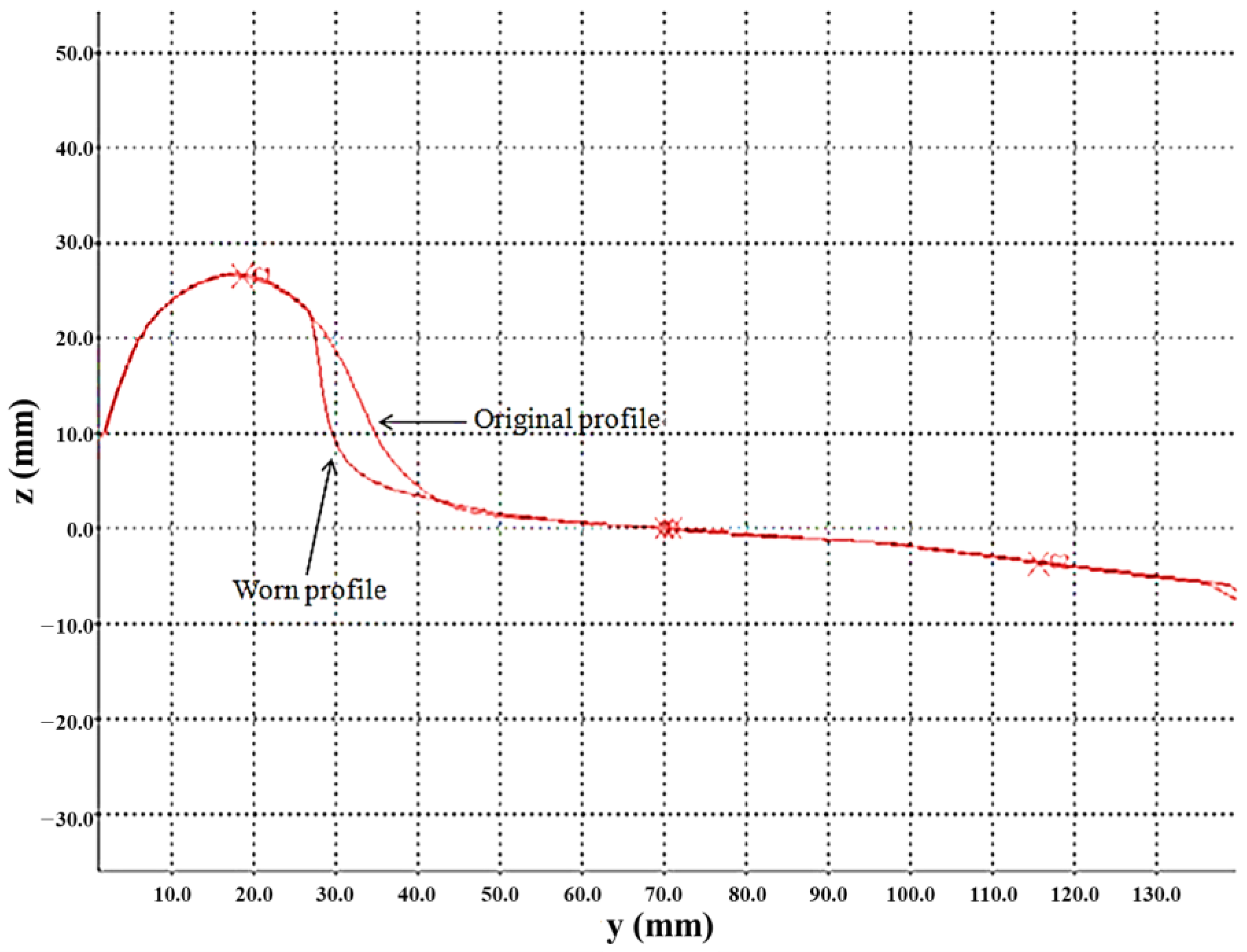
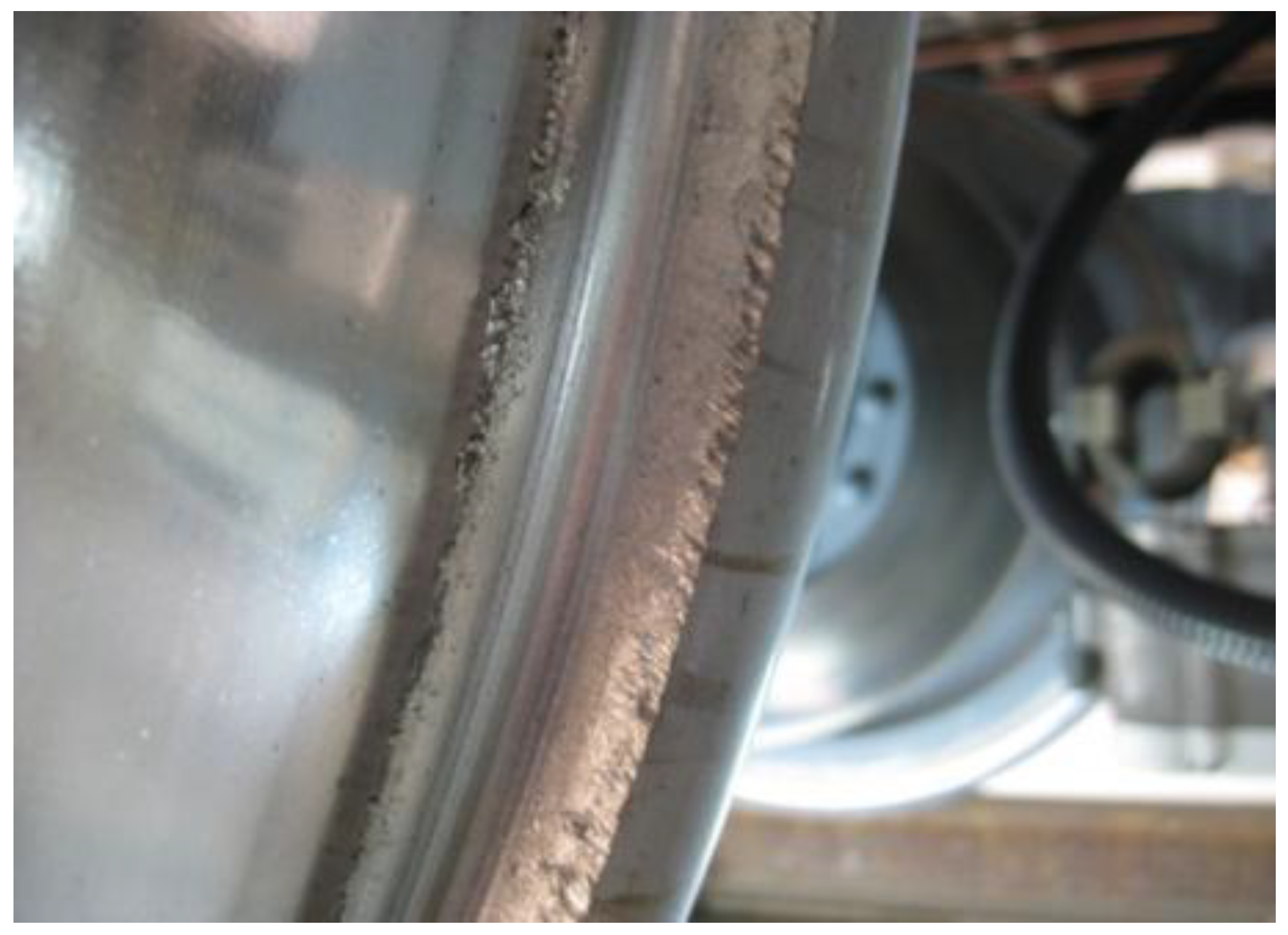
Figure 1 is the wheel wear shape of an actual city train, and shows the state of the worn wheel tread of a motor car which employs a tread brake with a composition brake shoe.
Figure 2 shows the result of evaluating the wear conditions of wheels, depending on the mileage of the city train. As seen in
Figure 2, if we take into account the fact that the accumulated mileage is approximately 10,000 km, the wheel flange wear level is evaluated to be severe.
Such wheel flange wear has occurred more in curved sections with a big radius of curvature of R350 where no rail lubrication system is installed than in curved sections with a radius of curvature of R250 where a rail lubrication system is installed. We can see that wheel flange wear in the sections with a radius of curvature between R310 and R400 where no rail lubrication system is installed has grown, as dry friction has occurred between the wheels and the rails, and due to the relatively high hardness of the heat-treated rails. In this way, a large amount of wear and fatigue damage occurs on the rail gauge and wheel flanges when a city train runs in a curved section, and the wheel profile has a great effect on wear and fatigue damage. Accordingly, to improve city train safety, wheel profile optimization is required for reduction of both wear and fatigue damage of wheel flange.
3. Multi-Objective Design Optimization of Wheel Profile
A design change of wheel profile not only reduces wear and fatigue that occur on the wheels, but also changes the performance, such as the contact pressure between wheels and the rails, creepage, and the dynamic behaviors of the vehicle. In the present study, derailment, lateral pressure, and vertical force are important in terms of the railway vehicle safety, and have been set as the constraints in relation to the wheel profile optimization to guarantee the safety of the railway vehicle’s dynamic performance [
23]. Formulation of wheel profile optimization design for city trains has been defined in such a way the objective functions of wear and fatigue are minimized at the same time, while the design performance constraints of derailment, lateral pressure, and vertical force are satisfied. The objective function of wear is defined as wear number, and is calculated from the creep forces and the creepages in the longitudinal, lateral, and spin directions at the contact point between a wheel and a rail. The wear model [
24] and the contact energy wear model [
25] of Archard are mostly used as wear estimation methods. The contact energy wear model is a wear theory based on the simple assumption that the frictional energy consumed by the creepage at the contact point between a wheel and a rail removes a certain amount of the metal material on the contact surface. A wear number is the energy diffused when friction occurs and is calculated as the product of creep force and creepage. The unit of wear number is Newton (N), and it allows relative comparison of the frictional energy diffused at the contact point. The objective function of fatigue is defined as a surface fatigue index. The surface fatigue index of the surface on which fatigue starts is based on a shake down map, and the surface fatigue index is dimensionless [
26]. Derailment among the design performance constraints is evaluated with a derailment ratio, and is defined using Nadal’s formula, which is widely used as the standard for evaluation of running safety [
27]. The force acting between a wheel and a rail is divided into the vertical force of wheel and the lateral force of wheel. A derailment ratio is expressed as the ratio of the lateral force (
Y) of the wheel and the vertical force (
Q) of the wheel acting between a wheel and a rail. The tolerable limit of derailment ratio is 0.8 in general. A derailment ratio is defined using the following expression:
where
is vertical force on wheel,
is lateral force on wheel,
is friction coefficient, and
is angle between the wheel flange and horizontal line.
Multi-objective function optimization design formulation of the wheel profile for a city train is defined as follows:
where
is longitudinal creep force,
is longitudinal creepage,
is lateral creep force,
is lateral creepage,
is spin creep force,
is lateral creepage,
is traction coefficient,
a,
b is semiaxes of the Hertzian contact patch,
k is yield stress on pure shear,
is longitudinal force,
is lateral creep force, and
is normal force. It is virtually impossible to find a solution that minimizes all of the objective functions in the process of simultaneously minimizing all of the objective functions. Therefore, NSGA-II-based multi-objective optimization generally selects a solution that is not dominated by other solutions among the recommended candidate solutions, and this solution is called a non-dominated solution. The NSGA-II algorithm is an algorithm for solving a representative multi-objective optimization problem that finds a Pareto-optimal solution classified as a non-dominant solution. Using this algorithm, we found the Pareto-optimal solution classified as the non-dominated solution, which is not dominated by other solutions, among candidate solutions that minimize both the wear and fatigue.
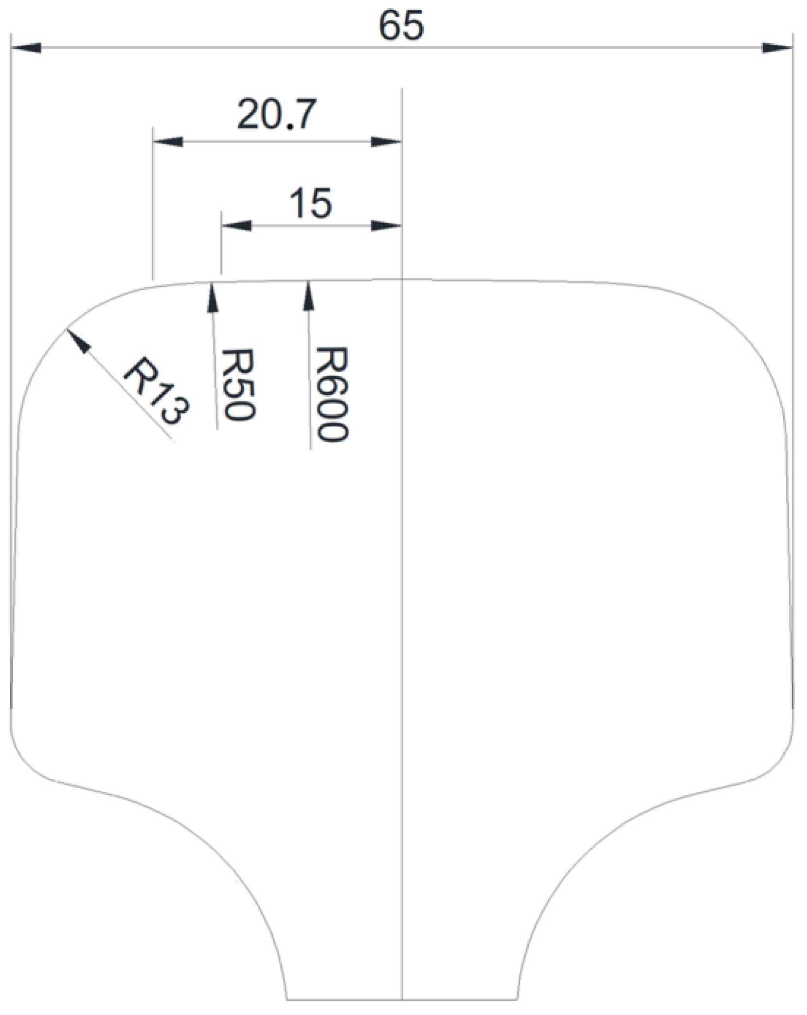
The design shape of the track profile contacting wheels is a conical 1/20 profile, and is shown in
Figure 3.
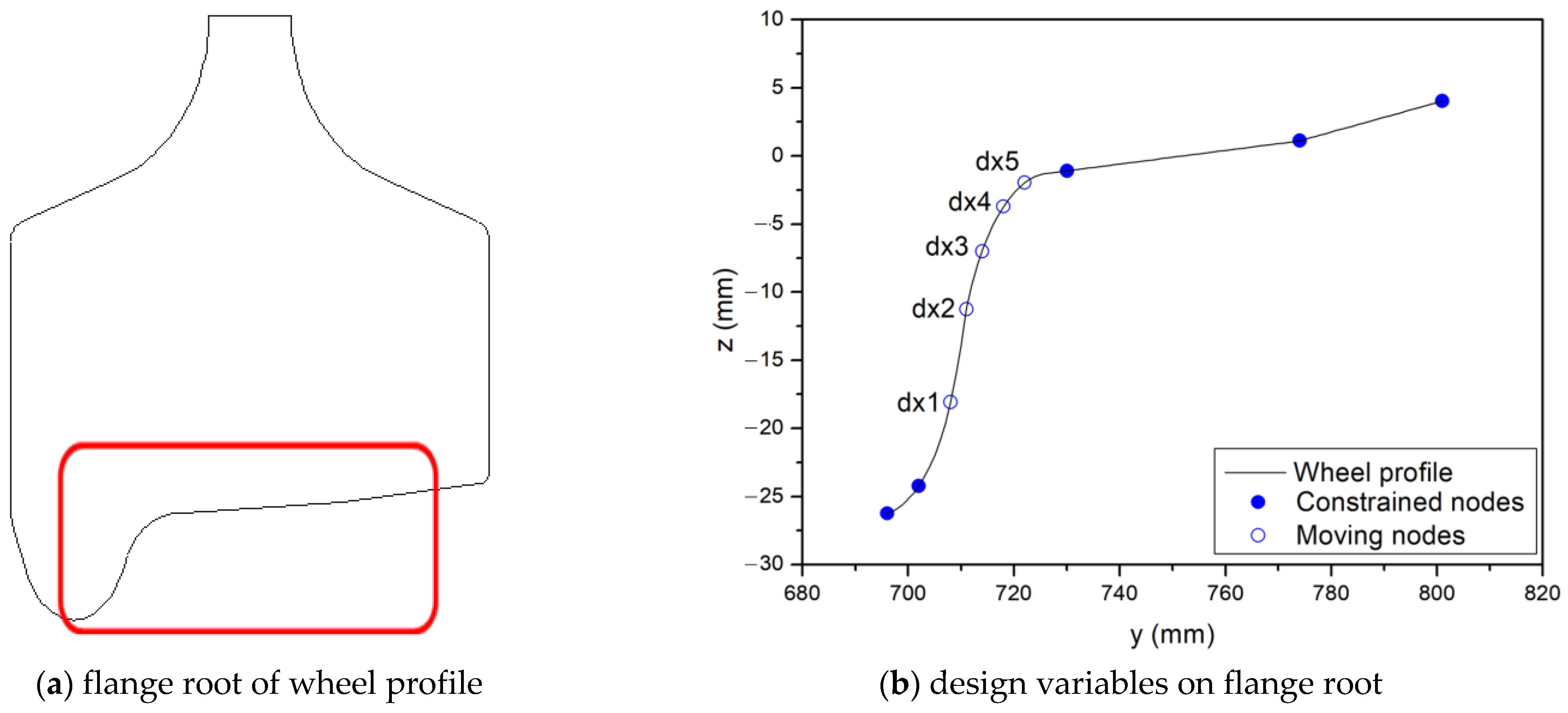
In a curved section, contact occurs between a wheel flange root or flange and a rail gauge corner. The area where the wheel is seriously damaged is the location of the inflection point of the flange in contact with the rail on the curved track. Therefore, the major inflection points (dx 1 to dx 5) were considered as design variables to search for the optimal profile that minimizes the wear and fatigue of the flange. To reduce the wear and fatigue which occur at a wheel flange root or a flange, five design variables were set so that the flange root and flange shapes of the wheel profile could be modified, as shown in
Figure 4.
As shown in
Figure 4, in order to reduce the fatigue and wear in curved sections while maintaining the dynamic performance, as well as the fatigue and wear characteristics in straight sections, the shape of the contacting wheel tread during driving in straight sections is maintained as it is. The wheel design variables create a profile with PCHIP (piecewise cubic hermite interpolating polynomial) [
28], moving in the direction of the profile normal line. To minimize the time it takes for the calculation, some nodes that do not have any effect on the contact between the tread and flange of the profile are fixed.
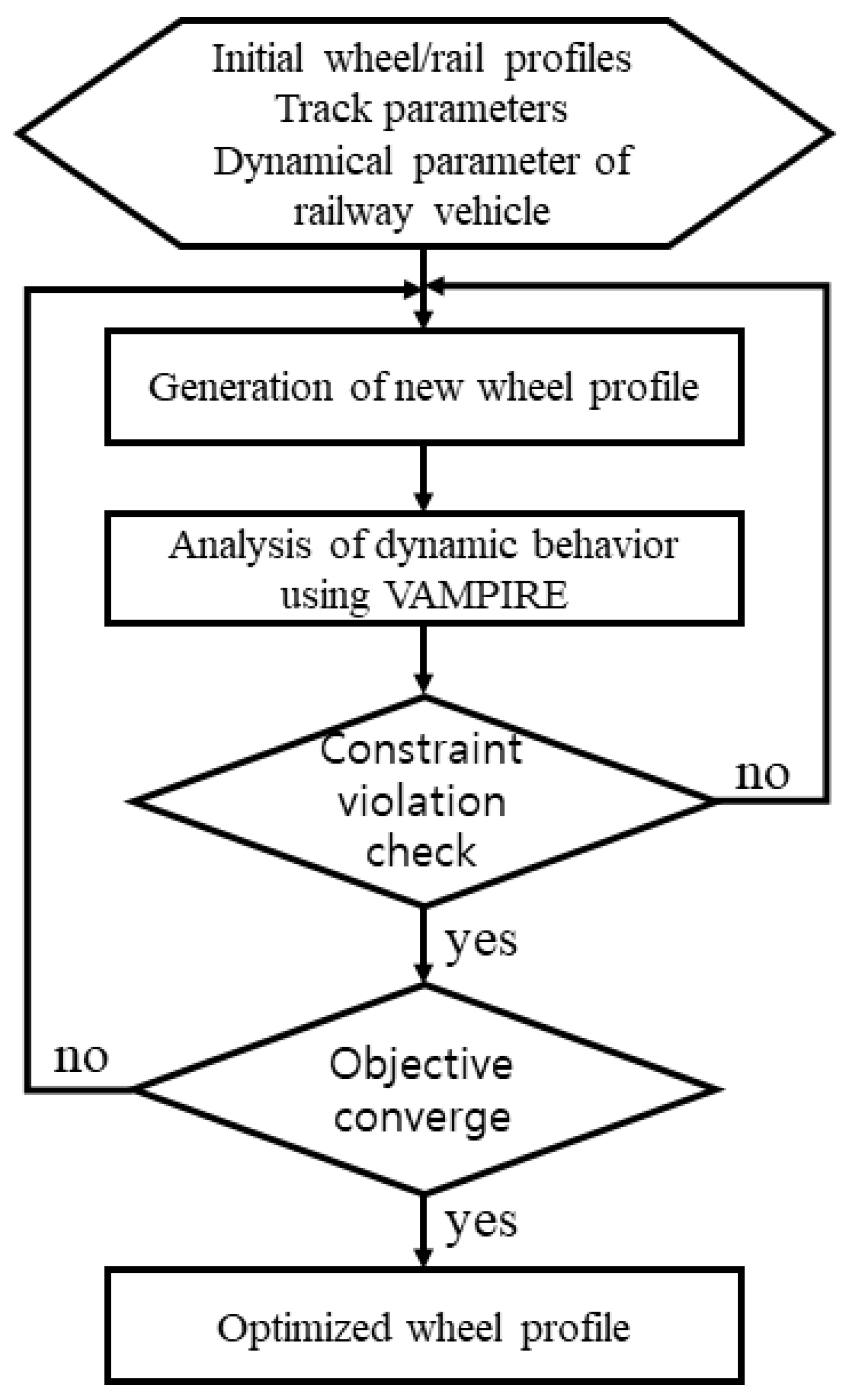
The optimum design procedure for a wheel profile applied to reduce the wheel gauge wear which occurs on sharp curves is shown in
Figure 5.
As shown in
Figure 5, the wheel profile, existing rail profile, track parameters, dynamics parameters of the railway vehicle, and so on, are entered at the first step, and the design domain required for a wheel profile design is set up. At the next step, a new wheel profile is created, and the dynamic behavior of the vehicle is calculated using a dynamics program. At the optimization step, the procedure is closed if the constraints and the objective function are satisfied and, if not satisfied, the procedure is repeated moving to the step of creating a new profile again until the constraints and objective function are satisfied. To analyze the contact behavior of the wheel profile, a dynamic performance analysis is conducted using VAMPIRE [
18], which is a program dedicated to railway vehicle dynamics. VAMPIRE allows users to organize mathematical models of nearly all railway vehicle forms based on the multi-body modeling method, and can efficiently evaluate actual performance of railway vehicle dynamics with high accuracy. The NSGA-II algorithm applied in this study first selects the initial population and determines whether the termination condition is satisfied. If the termination condition is not satisfied, an offspring group is created through tournament selection and reproduction, and a new population is created by combining the population and the offspring group. The non-dominated solution is sorted using the fast non-dominating sorting algorithm, and the sorting process is performed through the sorted non-dominating front and the crowding distance calculations. For the selected population, the population which is to evolve into the next generation is determined through crossover and mutation, and fitness is evaluated. This process is repeatedly performed until the termination condition is satisfied. In order to reduce the complexity of the non-dominated sorting method, the NSGA-II algorithm introduces the crowding distance to allocate resources more efficiently. In addition, the elitism that passes the optimal solution of the current generation to the next generation is applied to obtain a global optimal solution [
17].
In the present study, a train was set to be in the state of running on a curved track with a radius of curvature of R350 at a speed of 70 km/h, and the detailed design specification is put in order in
Table 1.
4. Results and Discussion
In the present study, we used the multi-objective function optimization method to develop a wheel profile that can reduce wear and fatigue of wheel flange at the same time when a train is running in a curved section. As to the multi-objective function optimization algorithm, we employed the NSGA-II (Non-dominated Sorting Algorithm-II) that uses a Pareto-optimal Solution, of which the usefulness has been verified as a result of having been widely used in various fields. NSGA-II is a fast and top class non-dominated sorting method that guarantees independence of the shared parameter designated by the user while maintaining the diversity of the solutions [
17]. The performance function was produced by simulating the movement of the vehicle in a curved section using VAMPIRE [
18], which is a program dedicated to railway vehicle dynamics, and the wear number and surface fatigue index, which are the objective functions, were calculated.
As for the parameters for multi-objective function optimization analysis, the population size was set to 100 individuals over 100 generations, the crossover rate to 0.9, the mutation rate to 0.1, and the relative tournament size was set to 0.5. A Pareto-optimal Solution produced using NSGA-II for the gene algorithm based on multi-objective optimization is shown in
Figure 6.
As shown in
Figure 6, the value that corresponds to the minimization of the wear number is the solution of ‘wear_opt’, and the value that corresponds to the minimization of the surface fatigue index is the solution of ‘fatigue_opt’. The design of ‘wear and fatigue_opt’ is the one selected among the solutions which satisfy both the minimization of wear number and the surface fatigue index. The optimum design variables of the wheel profile are put in order in
Table 2, and are compared with the initial design.
When a simplified wheel shaft consisting of a conical wheel profile, as shown in
Figure 4, runs on rails, only one contact point occurs between the wheel and the rail profiles. As the wheel shaft and the track system are symmetrical, if the center positions of the wheel shaft and the track match each other, the rolling radius of the left wheel (
r2) and the rolling radius of the right wheel (
r1) are the same. If the center of the wheel shaft shifts by Δ
y, the rolling radii of the right and left wheels become different from each other due to the conicity of the wheel, at which time a RRD (rolling radius different) occurs. A momentary difference between the rolling radii of the right and left wheels is a function of lateral displacement
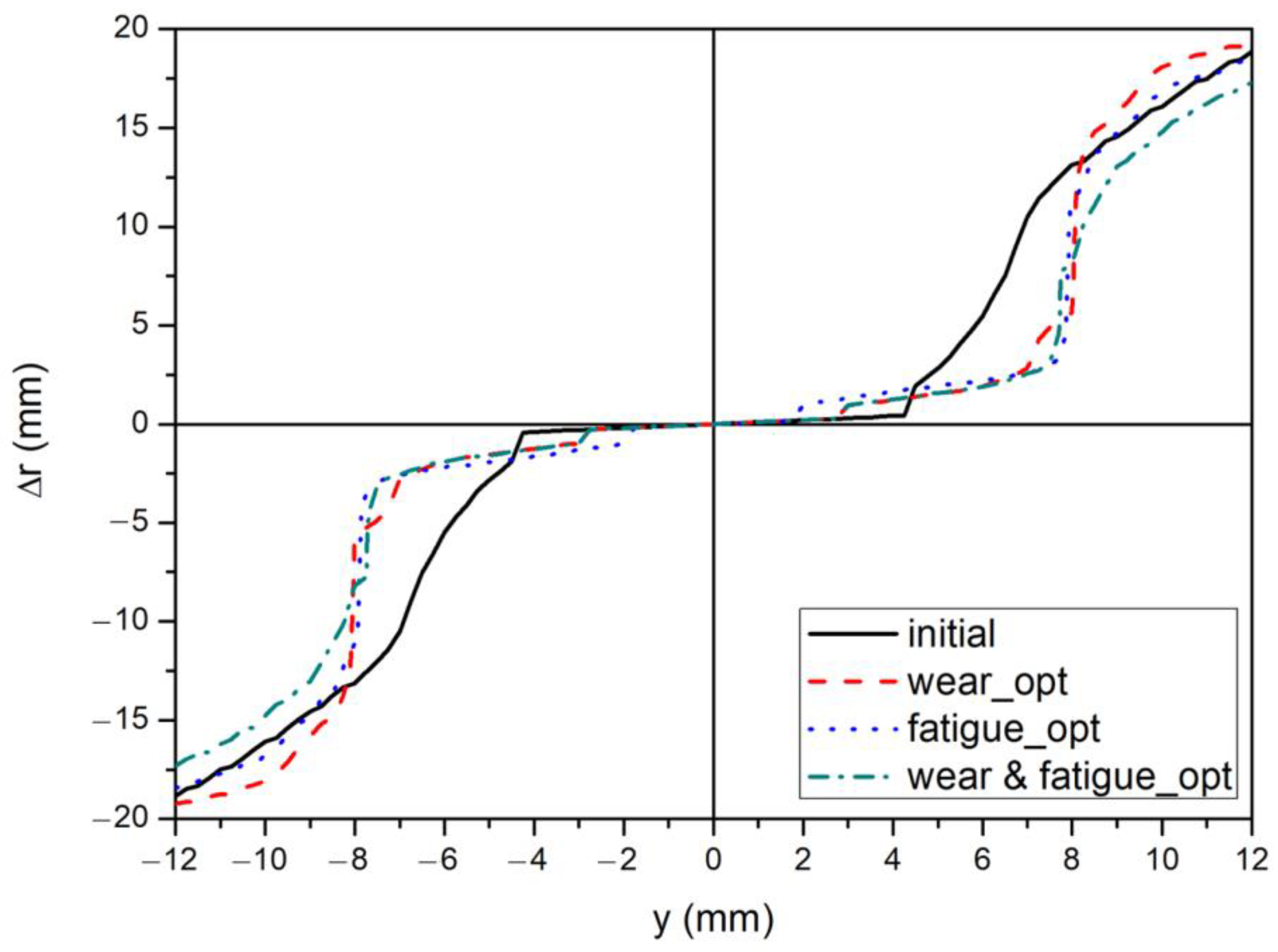
y of the wheel shaft in reference to the center of the wheel shaft and RRD(Δr) can be defined as follows:
As the RRD function is determined by the wheel and rail profiles, it is affected by the changes in the wheel shape caused by wear, and is a very important parameter in the wheel shaft dynamics. As an RRD is the difference between the radii of the outer and inner wheels at the contact point of a wheel and a rail, it is determined by the wheel and rail profiles, and affects sliding between the rail and wheel, wheel shaft safety, critical speed, and wheel shaft movement. As shown in
Figure 7, in the case of the optimized wheel profile, a bigger lateral displacement has occurred in curved sections than in the case of the existing profile, and the cases where the contact point between the wheel and the rail has more uniformly changed than in the case of the existing profile, as the RRD has changed softly.
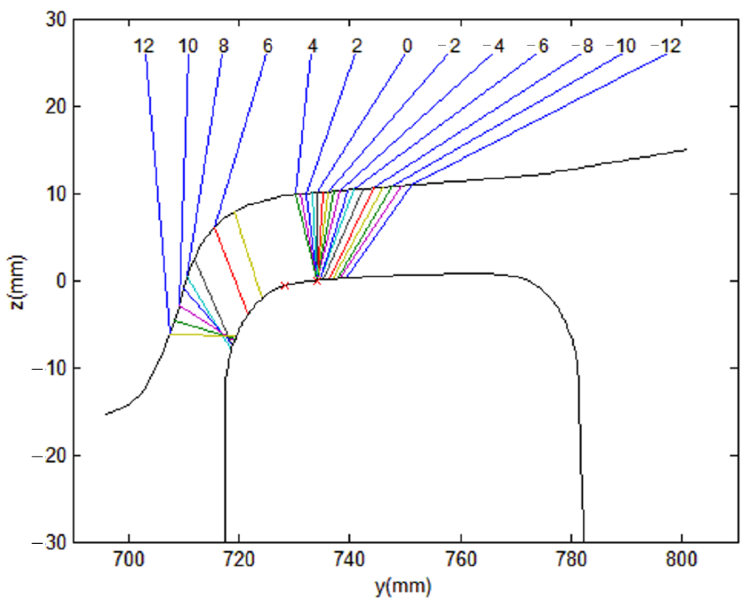
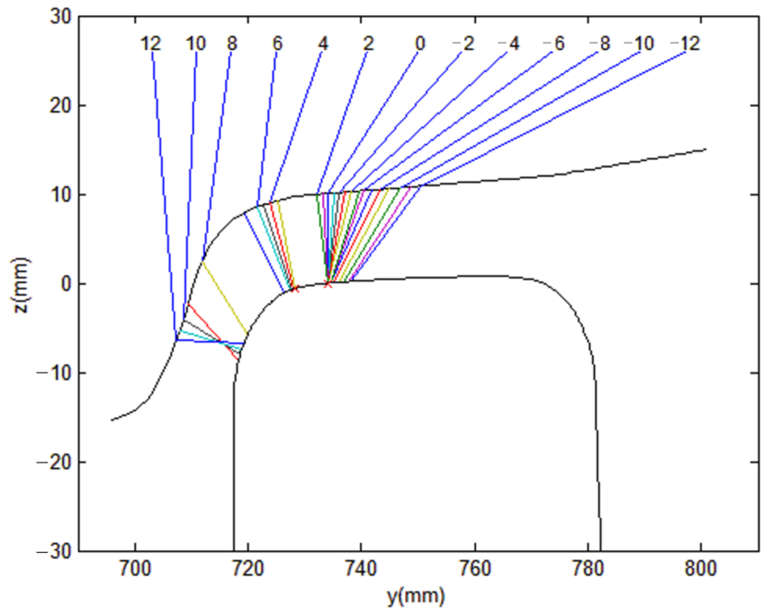
On the other hand, as the wheel tread profile has not been changed, the optimized profile is the same as the existing profile in straight sections. The contact point between the existing wheel and rail profile is shown in
Figure 8.
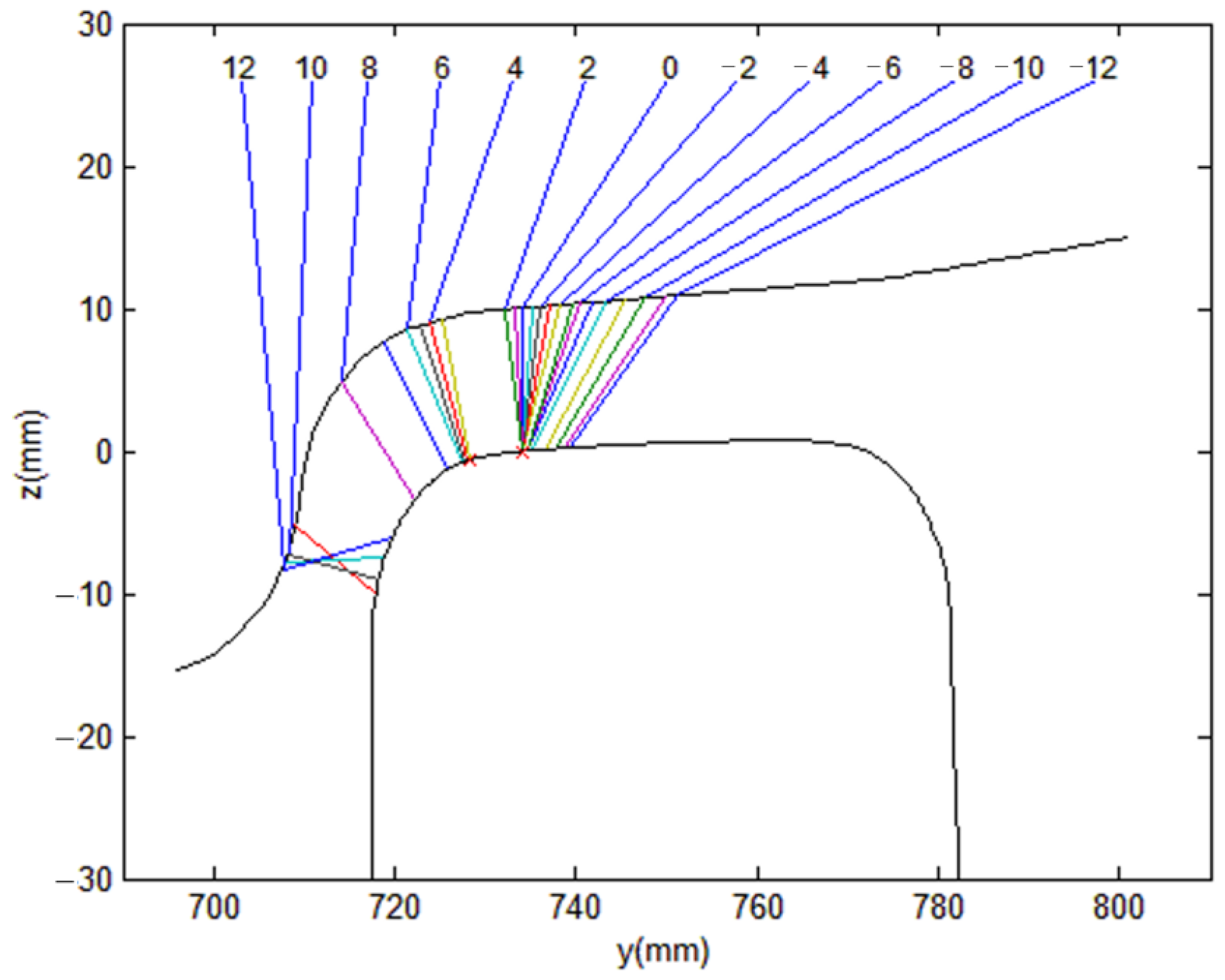
In general, the contact point between a wheel and a rail and an increase in the angle of attack affect the increase in the wear. An angle of attack is generated by the angle between the movement direction of the railway vehicle and the rail direction. An angle of attack affects the lateral pressure and vertical force, and an increase in the angle of attack leads to an increase in the wear. The location of the contact point between the wheel and rail profiles with optimized wear is shown in
Figure 9. Lateral displacement occurs between 3mm and 8mm in a curved section, and the wheel flange and rail gauge contact each other, as shown in
Figure 9, as a result of the lateral displacement.
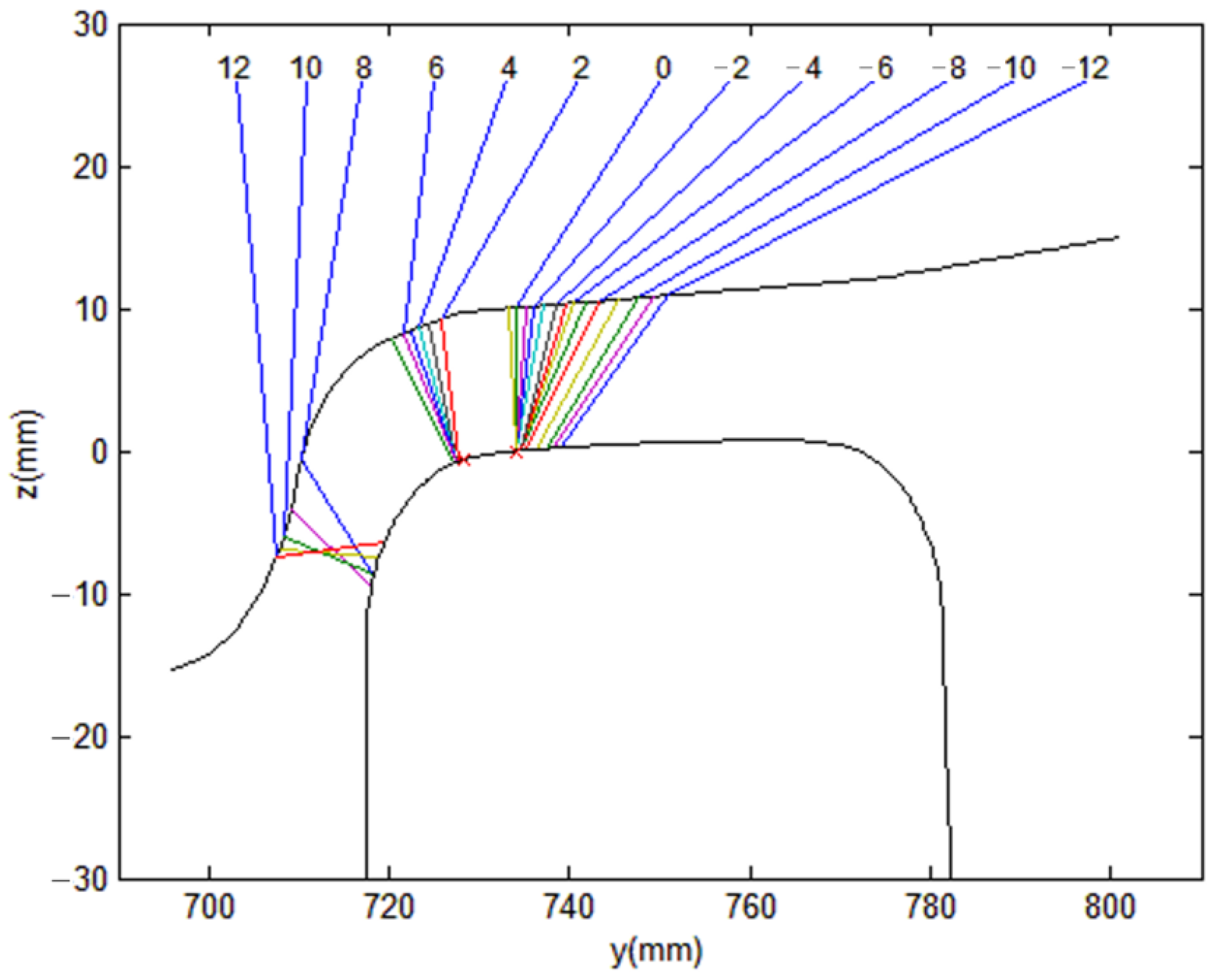
In this case, the contact point distribution of the profile with optimized wear is more uniform (that is to say, the jump at the contact point is smaller) than that of the existing profile. The location of the contact point between the wheel and rail profiles with optimized fatigue is shown in
Figure 10.
As shown in
Figure 10, the wheel flange and the rail gauge contact each other in a curved section at the point where the lateral displacement of the wheel is between approximately 2 mm and 8 mm. In the case of the profile with optimized fatigue, the contact points between the wheel and the rail are relatively concentrated on one point. The contact point distribution of the profile with optimized fatigue is not uniform when compared with that of the existing wheel profile.
Among the total 100 Pareto-optimal Solutions, the wheel design with optimized wear and fatigue was selected from the values between the wear number of the existing wheel and the wear number of the profile with optimized wear, and between the surface fatigue index of the existing wheel and the surface fatigue index of the profile with optimized fatigue. As shown in
Figure 11, in the case of the wheel design with optimized wear and fatigue, the flange contact occurs at the point where the lateral displacement of the wheel shaft is between 3 mm and 8 mm, and the jump between contact points is not great, and the contact points are quite uniformly distributed when compared to the existing profile.
As shown in
Figure 11, the jump at a contact point is relatively great when compared with the design with optimized wear. Accordingly, the wear number of the wheel profile with optimized wear and fatigue is between the wear numbers of the existing wheel and the wheel with optimized wear. The contact pressure of the wheel profile for which the wear and fatigue are optimized by the change in the wheel profile is between the contact pressures of the existing wheel and the wheel with optimized wear. Accordingly, the surface fatigue index of the design with optimized wear and fatigue is between the existing wheel design and the design with optimized fatigue.
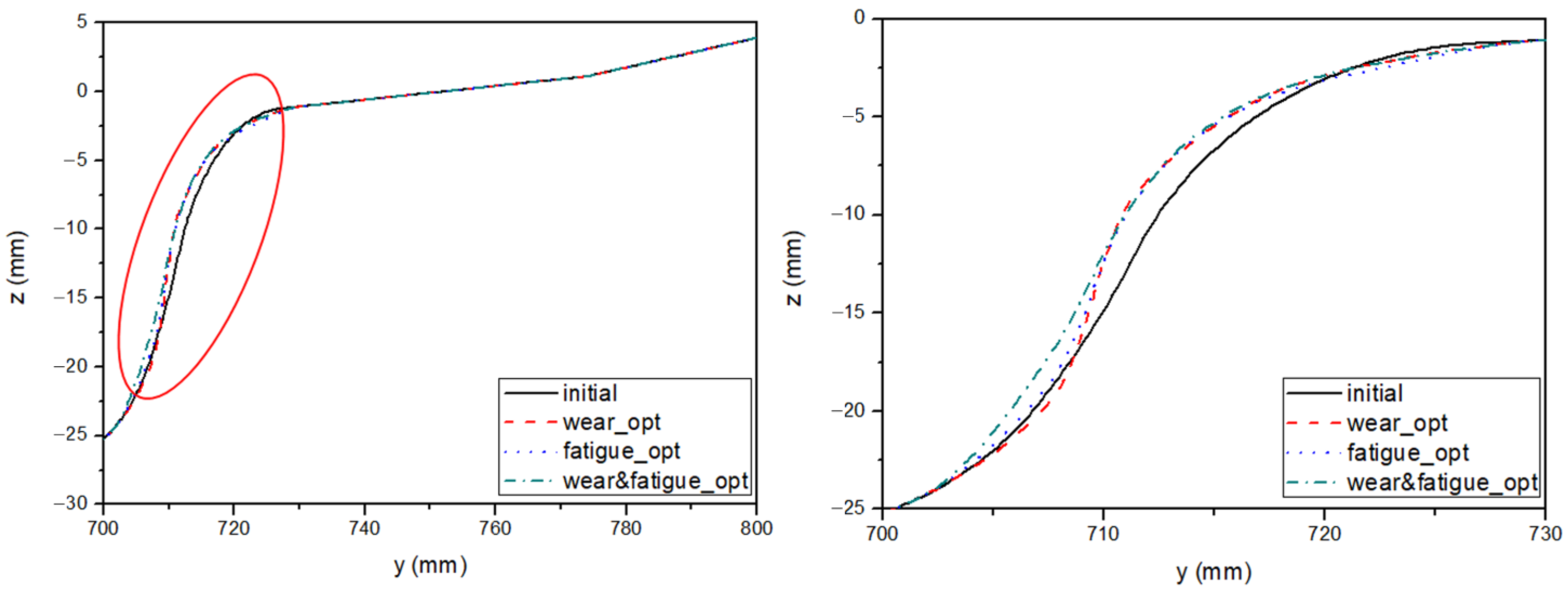
Figure 12 shows the comparison of the initial design wheel and the optimized wheel profile.
As shown in
Figure 12, the optimized wheel profile is shown to be similar to the worn profile in
Figure 2. When a vehicle moves in a curved section, the contact point between a wheel and a rail is located approximately between dx 2 and dx 5 of
Figure 4. The optimized flange inclination is less steep than that of the existing profile, and a bigger lateral displacement in a curved section aids smooth driving of the vehicle.
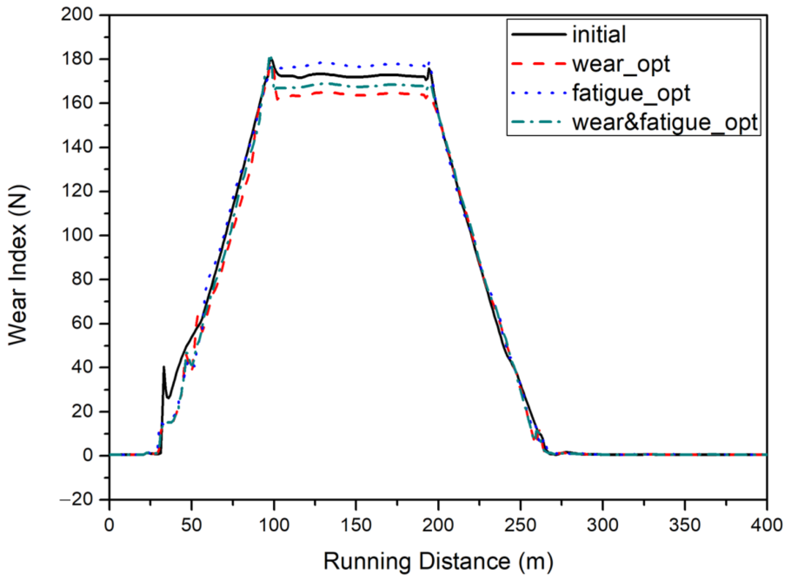
As the existing wheel tread profile is maintained when a new wheel profile is designed, the optimized profile has the wear number same as that of the existing wheel profile in straight sections. In the case of a two-point contact, the wear number is calculated by adding wear numbers arising from the two contacts. A wheel flange contacts a rail gauge corner in curved sections.
Figure 13 shows the wear numbers of the existing wheel and the optimized wheel profile.
In the case of the wheel profile with optimized wear, since the jump between contact points is uniform when compared to that of the existing wheel, the wear number has decreased. In the case of the wheel profile with optimized fatigue, since the jump is considerably great at the gauge corner as shown in
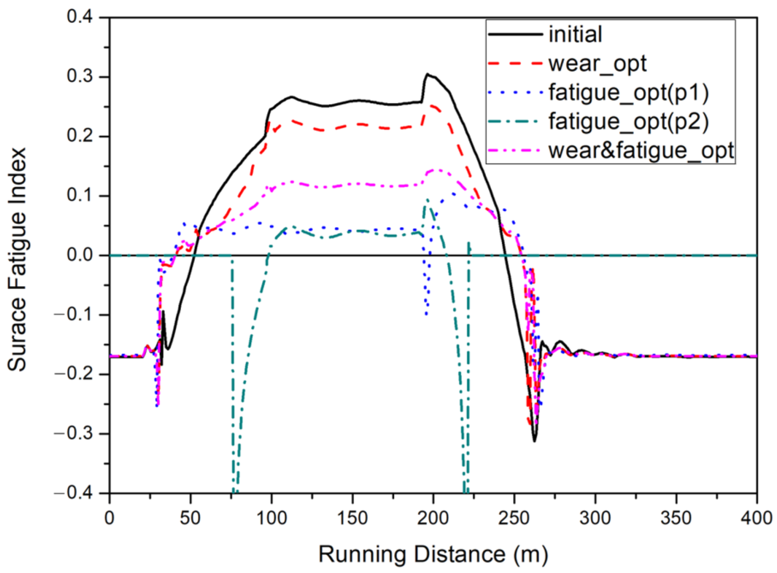
Figure 10, the wear number has increased. In the case of the profile with optimized wear and fatigue, the wheel shaft shifts by a lateral displacement of about 3 to 7 mm when driving in a curved section, at which point the contact points of the gauge are more uniformly distributed than in the case of the profile with optimized fatigue. In the case of the profile with optimized wear, the wear number on a sharp curve has decreased by approximately 4% when compared with that of the existing wheel profile, and the wear number of the profile with optimized fatigue has increased by approximately 17%, and that of the profile with optimized wear and fatigue has decreased by approximately 2%. The surface fatigue indexes of the wheel profiles are shown in
Figure 14.
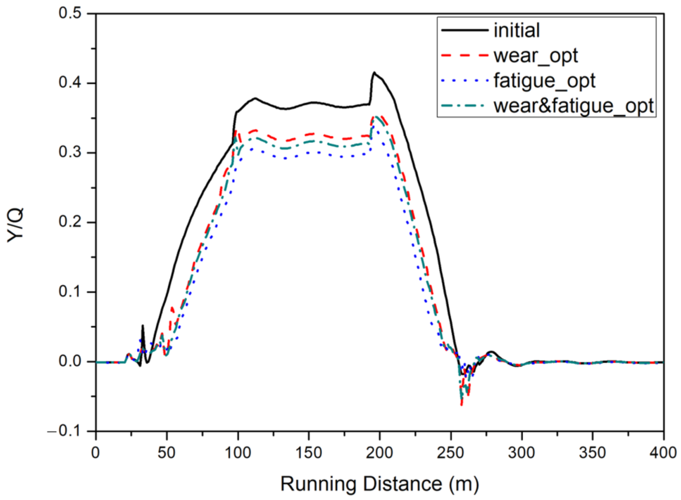
The optimized wheel of the wheel profile changes the location of the contact with the rail. In succession, this change at the contact point changes the contact area and with contact pressure. As the surface fatigue index is smaller than 0 in straight sections, no surface fatigue occurs. As the surface fatigue index is bigger than 0 in curved sections, fatigue cracks occur, and the bigger the surface fatigue index is, the bigger the possibility for fatigue cracks to occur. The contact pressures of the wheel profiles with optimized wear, optimized fatigue, and optimized wear and fatigue have decreased by 99%, 45%, and 58%, respectively, when compared with that of the existing wheel profile. The wheel with optimized fatigue has the lowest contact pressure, which is thought to have resulted from the occurrence of the two-point contact between the wheel and rail in the curved section. As contact takes place between the rail ball and the wheel tread and between the rail gauge and the wheel flange, respectively, in the case of two-point contact, the vertical force is applied and divided into two contact points. The best design to reduce the surface fatigue index is the wheel design with optimized fatigue, and is followed by the wheel design with optimized wear and fatigue, wheel design with optimized wear, and the existing wheel design in the order listed. The surface fatigue indexes of the wheel designs with optimized fatigue, optimized wear and fatigue, and optimized wear have been reduced by 65.8%, 52.8%, and 17.9% respectively. As the shape of the wheel flange where a contact occurs in a curved section is smoother than that of the existing profile, lateral pressure is reduced in the case of the optimized wheel profile. Therefore,
Figure 15 shows the derailment coefficients of wheel profiles, and that the derailment coefficients of the optimized wheel profiles have been reduced by approximately 13% when compared to that of the existing wheel.
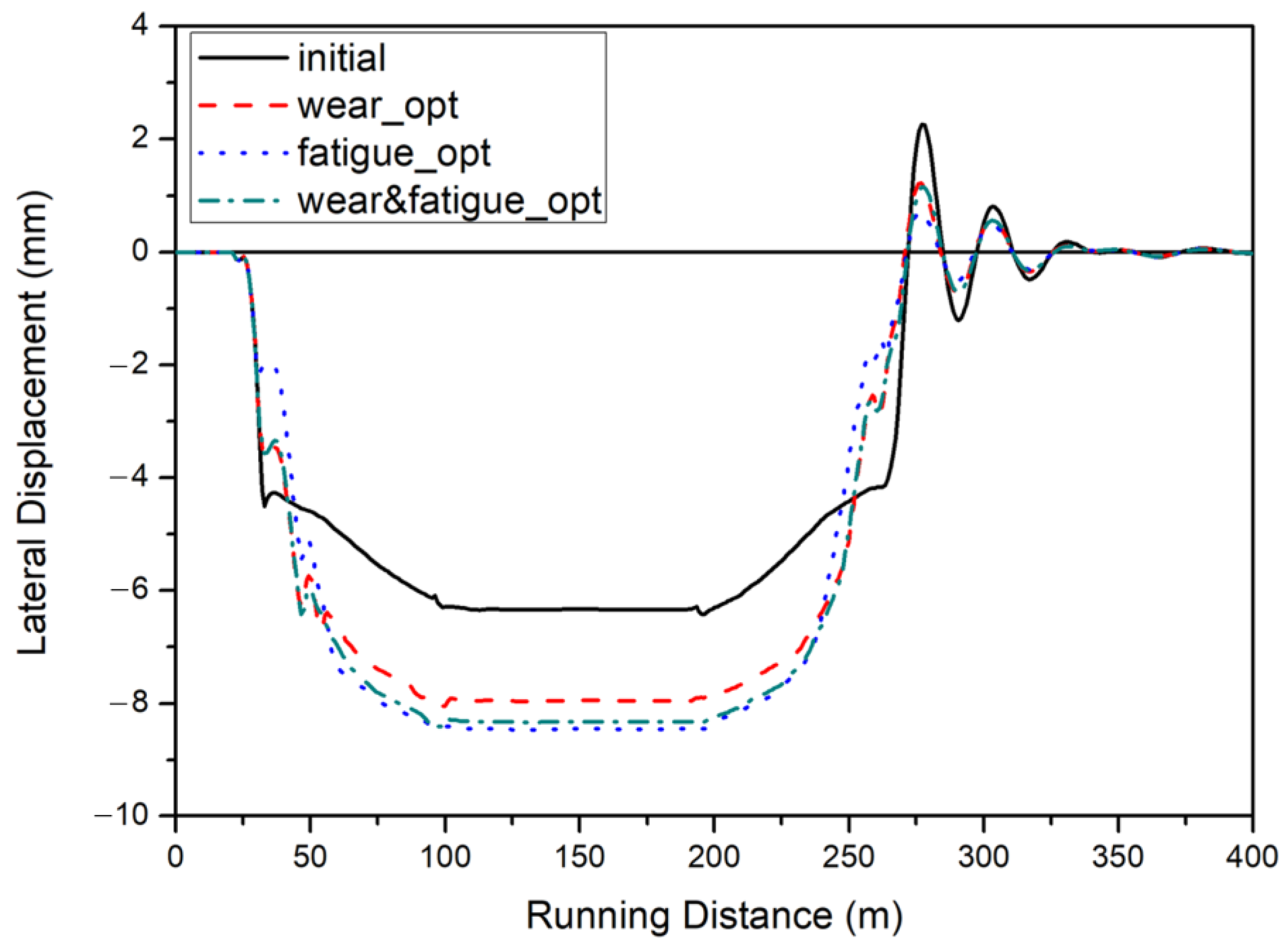
As shown in
Figure 16, the lateral displacement of the wheel shaft with optimized wheel profile after it has passed through a curved section is almost the same as that of the existing wheel. Accordingly, we can say that there is no change in the stability of the railway vehicle.
The wear number, surface fatigue index, derailment coefficient, lateral pressure, and vertical force as the results of the optimization are put in order and shown in
Table 3.
The inclination of the optimized profile is less steep that that of the existing profile. The lateral pressure has decreased and the vertical force has increased minorly.


