1. Introduction
The large settlement of tunnel vaults often occurs in soft-rock tunnels, mainly due to primary lining arch foot subsidence. The stability of the tunnel is a critical issue in the construction process [
1,
2]. If the settlement of the vault is not controlled, it may cause a large-scale collapse. At present, the most commonly adopted methods to control the subsidence of the arch foot include enlarging the arch foot, connecting the longitudinal beams, and installing feet-lock steel pipes (FLSPs) [
3]. Among these methods, FLSP has the advantages of simple construction and a remarkable ability to control the settlement [
4] and has been extensively utilized to control the settlement of tunnel vault in soft-rock areas [
5,
6,
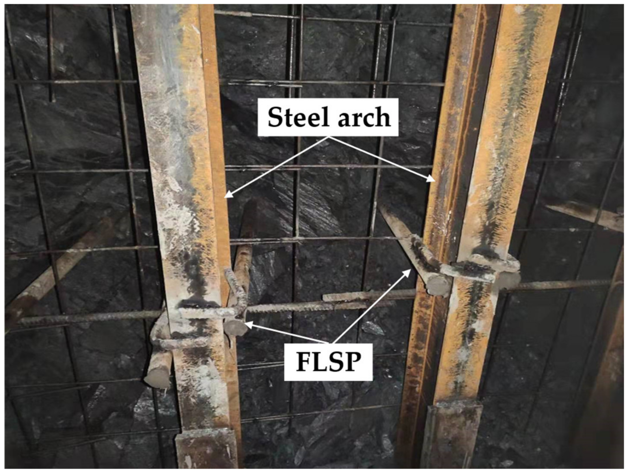
7]. The TFP is an inclined downward steel pipe with one end inserted into the surrounding stratum, and the other end welded to the steel arch [
8], as shown in
Figure 1. To explore and fully exploit the function of FLSP, it is necessary to carry out an in-depth study on the mechanical characteristics of FLSP and the selection of the relevant parameters.
At present, domestic and foreign scholars have carried out a series of studies on the mechanical characteristics of FLSP, utilizing theoretical analysis [
9,
10,
11], numerical simulation [
12,
13,
14], and field-test methods [
15,
16]. Chen et al. [
11] proposed an analytical method to predict the vertical load and settlement at the feet of steel ribs with the support of the feet-lock pipe and validated this method with the results of field measurements. Cui et al. [
14] explored the mechanism of action of foot-side reinforcement piles (FRSP) through model tests and numerical simulations and determined reasonable parameters. The results show that when the FRSP is long enough to cross the shear line, it can play a role in shear reinforcement, load redistribution, and internal pressure. FRSP effectively prevents the settlement of the tunnel and its surrounding foundations. Deng et al. [
17] compared the effect of the feet-lock bolt and the systematic bolt under the condition of a cracked surrounding rock tunnel through a field test and a numerical simulation. The results show that applying feet-lock bolts is a feasible option to replace systematic bolts in cracked surrounding rock tunnels. Luo et al. [
15] obtained the distribution law of the axial strain and the bending moment of the FLSP through electrical measurement and verified the accuracy of their test method by comparing the deformation of the pipe body before and after loading.
In summary, it can be seen that the theoretical research on FLSPs has been relatively comprehensive. However, there is a lack of research on the parameter selection and installation quantity of FLSPs in actual projects. FLSPs need to undergo a certain level of deformation before providing the corresponding bearing capacity. Based on the concept of prestressed steel bars, the active load-bearing of FLSP is worth exploring. In order to guide the construction and design of FLSPs, a design optimization method is proposed in this paper. Firstly, the problem of the load-deformation inconsistency of FLSPs in controlling the vault settlement is raised. Next, the process of the design optimization method is explained. Finally, the design method is applied to the Yulinzi Tunnel. The change in the vault settlement before and after the design optimization was analyzed by monitoring and measurement and is presented here.
2. Inconsistent Load-Deformation Problem of FLSPs
2.1. Action Mechanism and Load-Deformation Characteristics of FLSPs
2.1.1. The Action Mechanism and Simplified Model of a FLSP
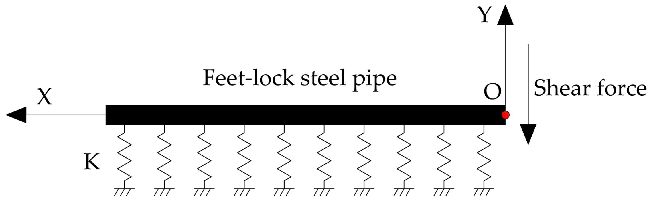
The force of FLSPs comprises two parts: on the one hand, the primary lining load (the axial force, the shear force, and the bending moment), and, on the other hand, the interaction between the FLSP and the surrounding rock (the friction along the direction of the pipe wall and the elastic stiffness perpendicular to the direction of the pipe wall). Under the primary lining axial load, FLSP exhibits displacement trends relative to the soil. The friction resistance between the soil and FLSP prevents the axial displacement of the FLSP. The FLSP bends under the shear and bending moment, and the soil resists deformation thanks to the elastic stiffness. Engineering practice shows that FLSPs mainly bear shear force, and the action between the FLSP and the primary lining is complicated. To simplify the calculation, the force between the FLSP and the primary lining is simplified as a pair of shear forces.
The mechanical analysis models of the interaction between the FLSP and the soil under shear force includes the Winkler, elastic continuum, and two-parameter foundation models. The Winkler model is shown in
Figure 2. The model assumes that the foundation reaction force received at any point of the FLSP is proportional to the deflection:
where P(
x) is the foundation reaction force per unit length of the steel pipe,
K is the elastic coefficient of the soil (MPa/m),
D is the outer diameter of the FLSP (m), and
y(
x) is the deflection of the FLSP (m).
When the FLSP is subjected to shear load at the end, the differential equation of its deflection curve is:
where
is the deformation coefficient of the FLSP, 1/
α is the characteristic length (m), E is the elastic modulus of the FLSP (N/m
2), and
Iz is the cross-sectional moment of inertia of the FLSP (m
4).
The general solution of the above formula is:
where A
1, B
1, C
1, and D
1 are constants determined by boundary conditions.
In the Winkler model, an infinite beam when
αL ≥
π can be considered. According to the force and displacement boundary conditions, the deflection curve equation of the FLSP under the action of concentrated force can be calculated by:
where
.
At the end of the FLSP (
x = 0):
To more intuitively express the influencing factors of the bearing characteristics of the FLSP,
and
can be substituted into Formula (5):
According to Formula (6), the lateral stiffness of the FLSP is:
2.1.2. Load-Deformation Characteristics of FLSP
A ϕ 42 × 4-millimeter (diameter of 42 mm and thickness of 4 mm) steel pipe 3.5 m in length is taken as an example to analyze the load-deformation characteristics.
Figure 3 shows the load-deformation curve of the FLSP according to Formula (6). The greater the deformation of the FLSP end, the greater the bearing capacity that the FLSP can provide. The deformation and bearing capacity change linearly. When the deformation of the FLSP end is 8.8 cm, the FLSP can provide a bearing capacity of 90 kN.
2.1.3. Influencing Factors and Laws of Load-Deformation Characteristics
Combined with Formula (6), the load–pipe-end deformation laws of the FLSP under different parameter conditions were analyzed.
- (1)
Diameter of FLSP
Taking the FLSP with a length of 3.5 m and a wall thickness of 4 mm as an example, the pipe-end deformation–load characteristics of the FLSP with different diameters were analyzed. The foundation reaction coefficient was taken as 100 MPa/m. According to Formula (6), the deformation corresponding to the multi-level load was calculated. The deformation–load relationship curves of different diameters were drawn, as shown in
Figure 4. According to the steel-pipe cross-sectional area, length, and density, the weight of the steel pipe was calculated, as shown in
Table 1. By combining
Figure 4 and
Table 1, it can be concluded that the bearing capacity of the ϕ89 steel pipe is three times that of the ϕ42 steel pipe under the same deformation, while the weight of the ϕ89 steel pipe is only twice that of the ϕ42 steel pipe. FLSPs of a large diameter can provide a greater bearing capacity per unit of weight under the same pipe-end deformation conditions. However, it is also necessary to consider the balanced selection of the drilling diameter range of the drilling equipment.
- (2)
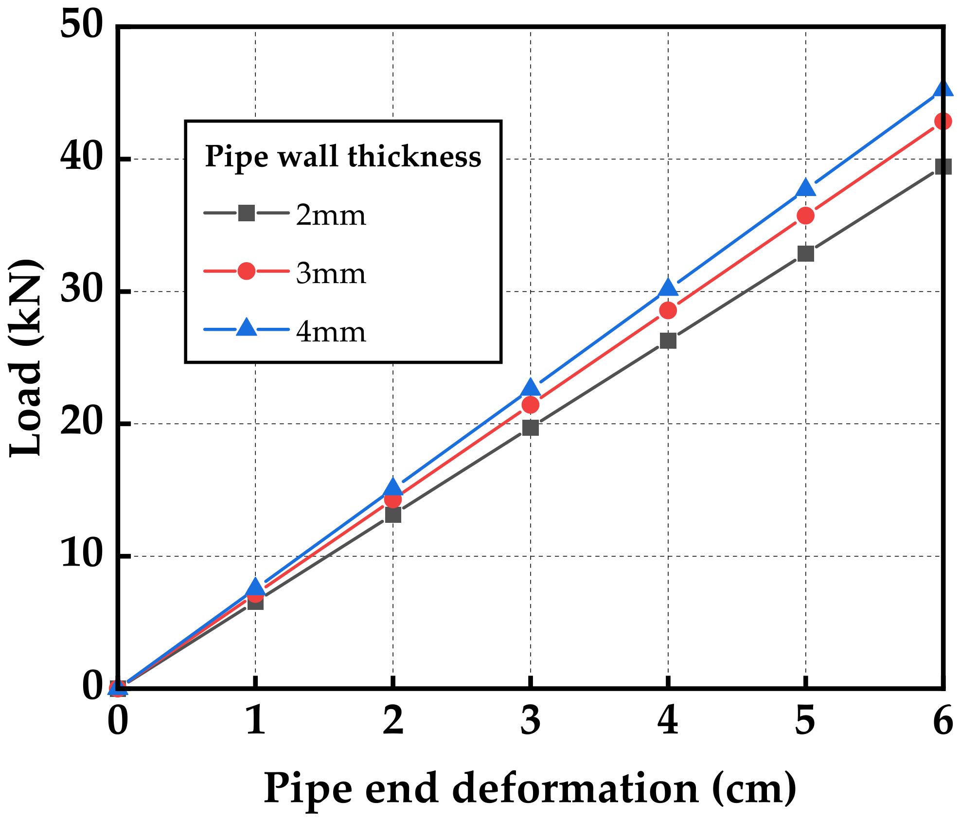
Wall thickness of FLSP
Taking the FLSP with a length of 3.5 m and a diameter of 42 mm as an example, the pipe-end deformation–load-characteristics of the FLSP with different wall thicknesses were analyzed. The foundation reaction coefficient was taken as 100 MPa/m. The pipe-end-deformation–load-relationship curves with varying FLSP wall thicknesses were drawn, as shown in
Figure 5. It can be seen from the figure that under the same deformation conditions, the difference in the bearing capacity of the FLSP with a 2.0-millimeter wall thickness and 4.0-millimeter wall thickness is less than 15%. The wall thickness has little effect on the pipe-end deformation–load characteristics of the FLSP. It can be seen from
Table 1 that the weight of the steel pipe with the 4.0-millimeter wall thickness is twice that of the steel pipe with the 2.0-millimeter wall thickness. Under the same deformation conditions, the unit weights of thin-walled steel pipes can provide more bearing capacity.
- (3)
Foundation reaction coefficient
Taking the FLSP with a length of 3.5 m, a diameter of 42 mm, and a wall thickness of 4 mm as an example, the pipe-end deformation–load characteristics of the FLSP under the conditions of different foundation reaction coefficients were analyzed. The deformation-load curves under the conditions of varying foundation reaction coefficients were drawn. As shown in
Figure 6, the larger the reaction coefficient of the surrounding rock, the stronger the capacity to constrain the deformation of the FLSP. Therefore, the grouting method can be adopted to increase the reaction coefficient when encountering soft surrounding rock, which can provide a large bearing capacity when the FLSP has a small displacement and reduce the settlement of the vault.
2.2. Deformation Characteristics of Primary Lining under the Action of Arch Foot Bearing Capacity
The primary lining transfers the surrounding rock pressure generated by the tunnel excavation to the foundation and the FLSP. The primary lining relies on the bearing capacity provided by the arch foot to limit the deformation of the surrounding rock. The foundation bearing capacity supplied by the soft stratum is minimal, and can be ignored. Here, only the bearing capacity provided by the FLSP is considered.
Taking the Yulinzi Tunnel as an example to analyze the deformation characteristics of the primary lining under the action of various arch foot bearing capacities, the analysis model was established, as shown in
Figure 7. The elastic–plastic model based on the Mohr–Coulomb strength criterion was adopted for the soil mass, and the soil parameters were obtained by using a direct shear test. The material parameters are shown in
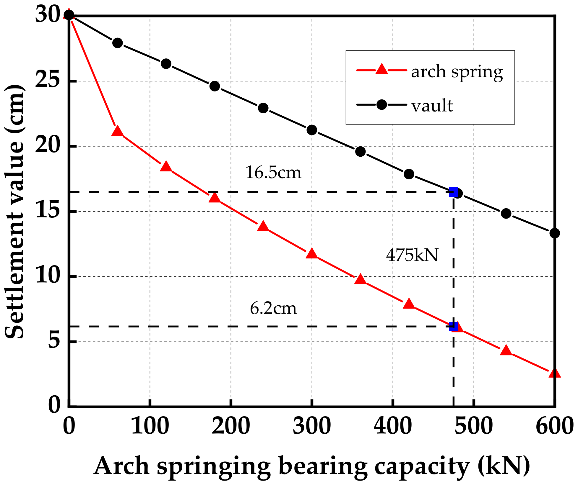
Table 2. The foundation bearing capacity provided by the soft foundation is ignored in the model. The change curve of the vault settlement and arch foot subsidence of the primary lining with various arch foot bearing capacities was obtained through a numerical analysis, as shown in
Figure 8. The vault settlement and the arch foot subsidence of the primary lining decrease with the increase in the arch foot bearing capacity, and the overall change is linear. When the primary lining vault settlement is 16.5 cm, the required arch foot bearing capacity is 475 kN, and the corresponding arch foot subsidence is 6.2 cm.
2.3. The Load-Deformation Inconsistency Problem of the FLSP
Taking the Yulinzi Tunnel as an example, we illustrate the load-deformation incoordination problem of the FLSP. According to the deformation characteristics of the primary lining in
Section 2.2, it was concluded that when the vault settlement is controlled at 16.5 cm, the bearing capacity provided by the arch foot is 475 kN, and the arch foot subsidence of the primary lining is 6.2 cm. Because the numerical analysis adopts a plane model and the distance between the steel arches is 0.75 m, the bearing capacity required from the FLSP is 356 kN.
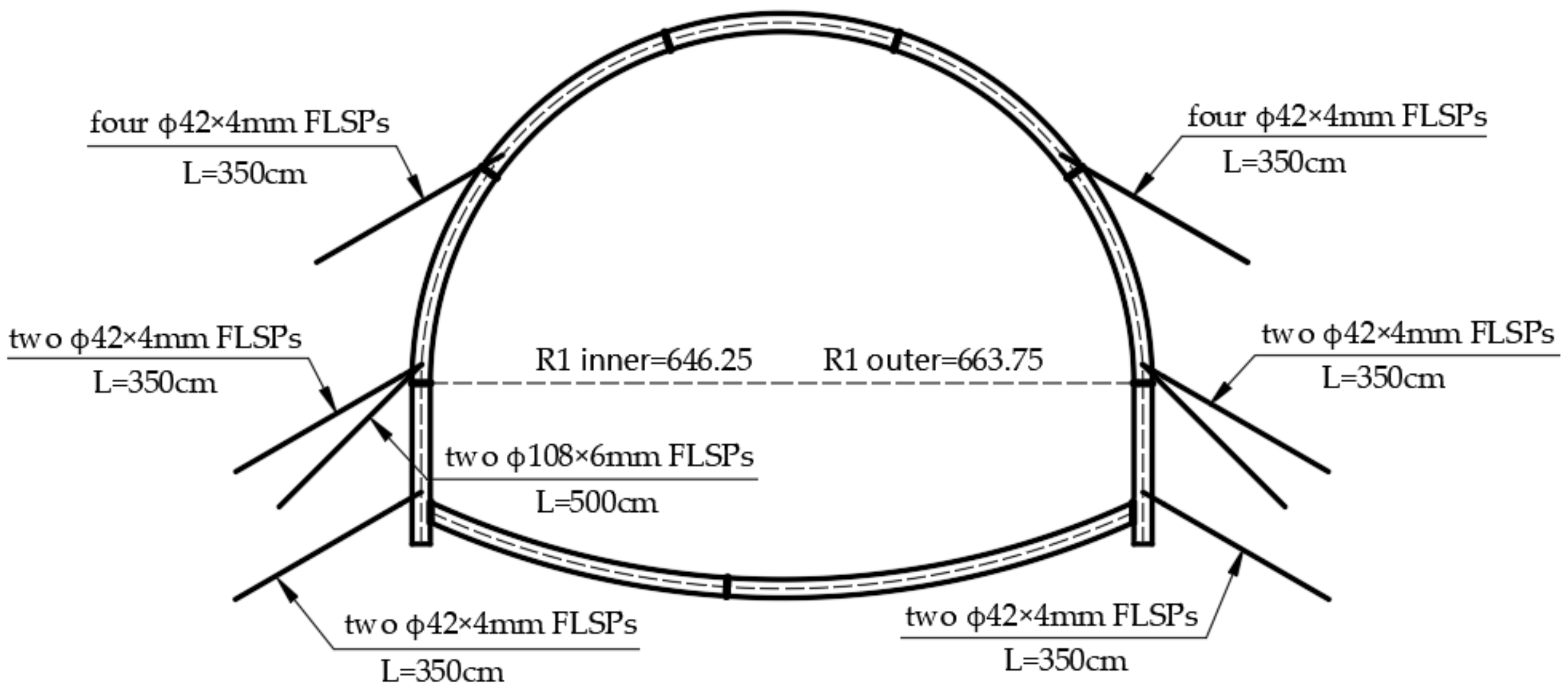
In the original design, four ϕ42 × 4 mm FLSPs 3.5 m in length are installed on the upper bench, as shown in
Figure 9. The required bearing capacity of a single ϕ42 × 4-millimeter FLSP is approximately 90 kN. When the deformation value of a single ϕ42 × 4-millimeter FLSP has an arch foot subsidence value of 6.2 cm, it can provide a bearing capacity of 63 kN, but cannot reach the 90 kN required to control the settlement. The original FLSP cannot control the vault settlement within the range of 16.5 cm. Combined with the load-deformation characteristics of the FLSP in
Section 2.1.2, it can be concluded that the FLSP provides a bearing capacity of 90 kN, and that the FLSP end needs to be deformed by 8.8 cm. At this point, the deformation value of the FLSP is greater than the primary lining arch foot subsidence value of 6.2 cm. There is a problem of deformation inconsistency between the FLSP and the primary lining arch foot.
3. Design Optimization Method of FLSP Based on Load-Deformation Coordination
At present, the installation quantity and the parameters of FLSPs in tunnel design and construction mostly rely on relevant engineering experience and lack theoretical support. To solve the problem of the load-deformation inconsistency between the FLSP and the primary lining, a design optimization method for FLSPs is proposed for two working conditions: predicted large deformation and occurring large deformation.
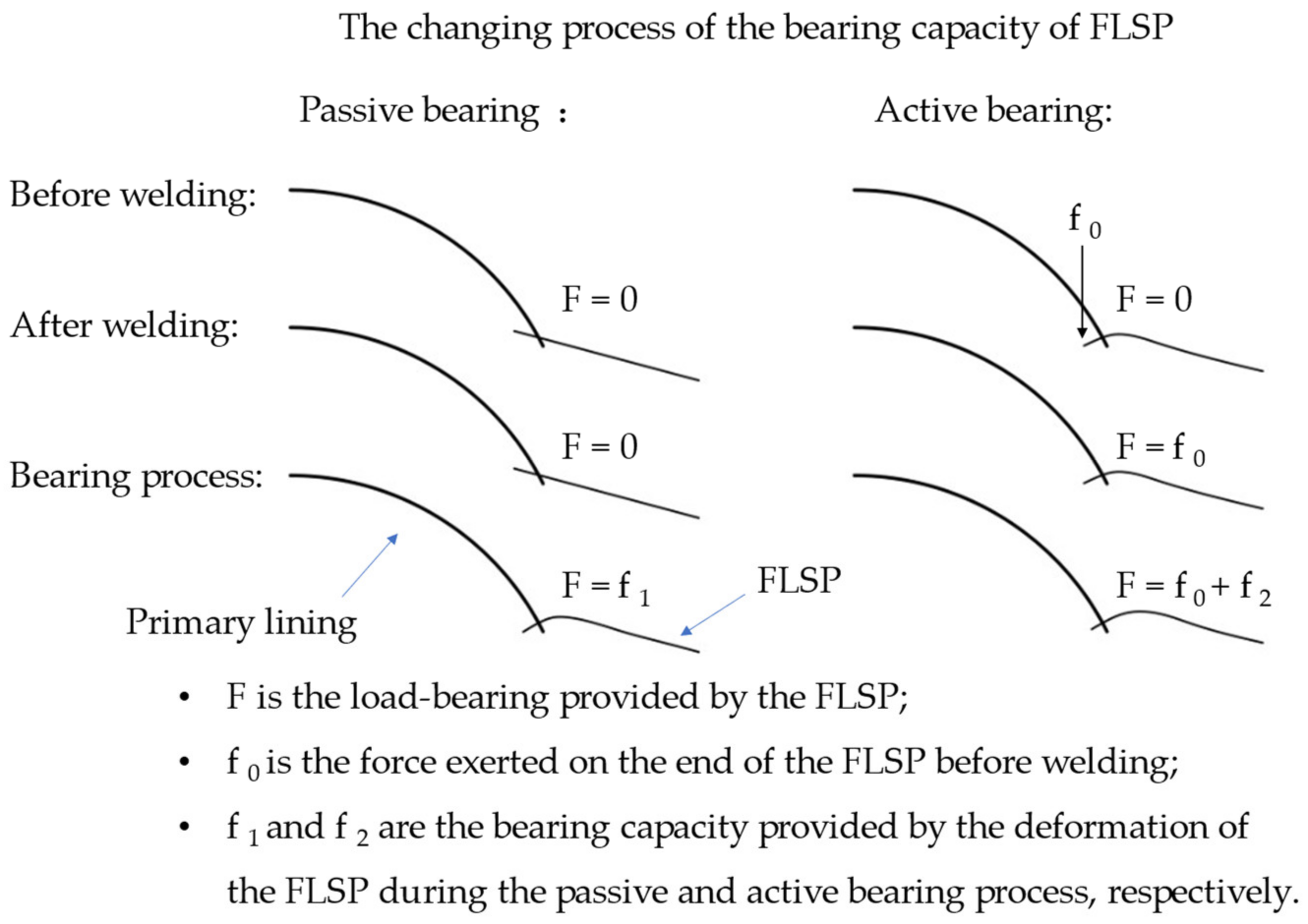
From the pipe-end deformation-load characteristics of the FLSP, it can be concluded that the FLSP needs to be deformed to provide the corresponding bearing capacity. The FLSP is deformed under the primary lining load and then provides the bearing capacity, referred to as passive bearing. To rapidly and fully exert the bearing capacity of the FLSP, the method of pre-compressing the FLSP before connecting it with the primary lining is proposed. The FLSP can actively provide the bearing capacity, referred to as active bearing. A comparison between active and passive bearing is shown in
Figure 10. The following describes the design optimization method of the FLSP.
3.1. Predicted Large Deformation
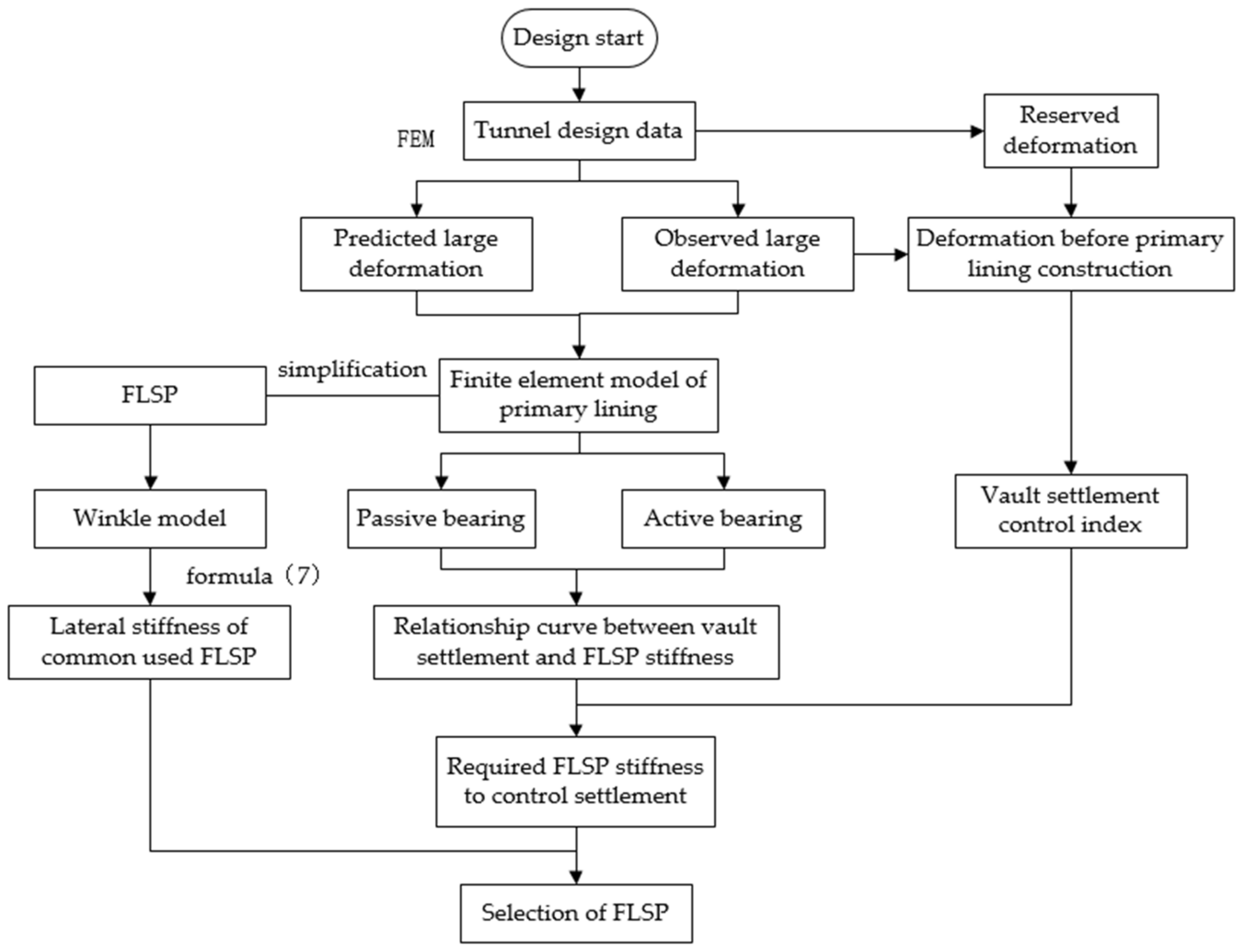
When the numerical simulation method is applied, and it is judged that a large deformation will occur after tunnel excavation, the design optimization process of the FLSP shown in
Figure 11 is applied. The design stage consists of four parts: the extraction of the vault settlement control index, the simplification and stiffness calculation of the FLSP, the finite element analysis of the primary lining, and the selection of the FLSP.
3.1.1. Extraction of Vault Settlement Control Index
First of all, the reserved deformation of the tunnel is obtained from the design data. The reserved deformation is an essential index in the design of a tunnel. If the reserved deformation is too large, it increases the concrete volume of the secondary lining and the project cost. By contrast, if the reserved deformation is too small, the primary lining encroaches on the limit, resulting in the dismantling of the arch. For soft surrounding rock, Section 6.2.5 of the “Technical Specifications for Railway Squeezed Surrounding Rock Tunnels” (Q/CR 9512-2019), gives the reference reserved deformation, as shown in
Table 3.
3.1.2. The Simplification and Stiffness Calculation of the FLSP
The connection between the FLSP and the primary lining is complicated. The following assumptions were made to simplify the analysis:
- (1)
Without considering the foundation bearing capacity, it was assumed that the FLSP bore all of the surrounding rock loads, and that the design was biased towards safety;
- (2)
The bending moment between the FLSP and the primary lining was ignored;
- (3)
The role of the FLSP is to limit the sinking of the arch foot, so the axial force of the FLSP was ignored, and only the lateral bearing effect was considered;
Therefore, only the shear force between the FLSP and the primary lining was considered. Several standard diameters and wall thicknesses of FLSPs applied in engineering practice were selected, and combined with Formula (7) to obtain the lateral stiffness of the FLSP.
3.1.3. Finite Element Analysis of Primary Lining
According to the engineering geology and construction drawing data, the finite element analysis model of the surrounding rock and the primary lining was established. The finite element analysis model simplified the FLSP as a spring connected to the primary lining and simultaneously realized the deformation coordination between the FLSP and the primary lining. The spring stiffness indicated the lateral stiffness of the FLSP. In the active load-bearing design analysis model, the active load-bearing effect is achieved by pre-compressing the spring before releasing the surrounding rock load. The curve between the spring stiffness and the settlement of the arch foot and vault was obtained by changing the spring stiffness. Finally, the required lateral stiffness of the FLSP was obtained according to the vault settlement control index.
3.1.4. Type Selection of FLSP
On the basis that the combined lateral stiffness of the FLSP was not less than the required lateral stiffness, the selection of the FLSP was carried out according to the principle of the least amount of steel.
3.2. Observed Large Deformation
When the surrounding rock has undergone a large deformation before the primary lining construction, the design optimization process of the FLSP shown in
Figure 9 is applied. The overall design process is the same as the prediction of large deformation, differing only in the following two aspects:
- (1)
Because the large deformation occurs before the primary lining construction, the vault settlement control index is no longer the reserved deformation of the tunnel; it should instead be the reserved deformation minus the vault settlement before the primary lining construction. The vault settlement can be obtained through monitoring and measurement.
- (2)
During the finite element analysis of the primary lining, the stress should be released to the large deformation state. Next, the remaining stress is released after the primary lining construction. Similarly, it can be divided into two schemes: passive and active bearing. Because of the small allowable vault settlement, it is recommended to adopt the active bearing scheme of the FLSP to ensure the full exertion of the bearing capacity of the FLSP.
4. Case Study
Taking ZK279 + 840–860 of the Yulinzi Tunnel’s left line in Zhengning County, Qingyang City, as an example, the optimized design of the FLSP was carried out. The surrounding rock was paleosol loess, the parameters of which are shown in
Table 2. The buried depth of the tunnel, which is constructed by the three-bench seven-step method, was 50 m, and the excavation height of the upper bench was 3.8 m. The steel arch frame adopted an I20b beam, and the steel arch frame spacing was 75 cm. The shotcrete adopted C25 concrete, with a thickness of 24 cm, and the reserved deformation of the tunnel was 30 cm.
According to the available research, the vault settlement and peripheral convergence have the fastest deformation rate in the upper bench excavation stage [
18]. The FLSPs installed in the upper bench play a crucial role in controlling the vault settlement. This paper takes the upper bench excavation as an example to select and design the FLSP. According to the measured settlement data of the on-site tunnel excavation, the vault settlement after upper bench excavation by the three-bench method was 55% of the maximum settlement value, so the control deformation of the upper bench was 16.5 cm. According to the concept of NATM, the secondary lining does not bear the load in theory and acts only as a safety reserve. In fact, it needs to bear 30% to 40% of the load in the soft surrounding rock. Here, the secondary lining bore 30%, the primary lining bore 70%, and the upper bench excavation bore 30%.
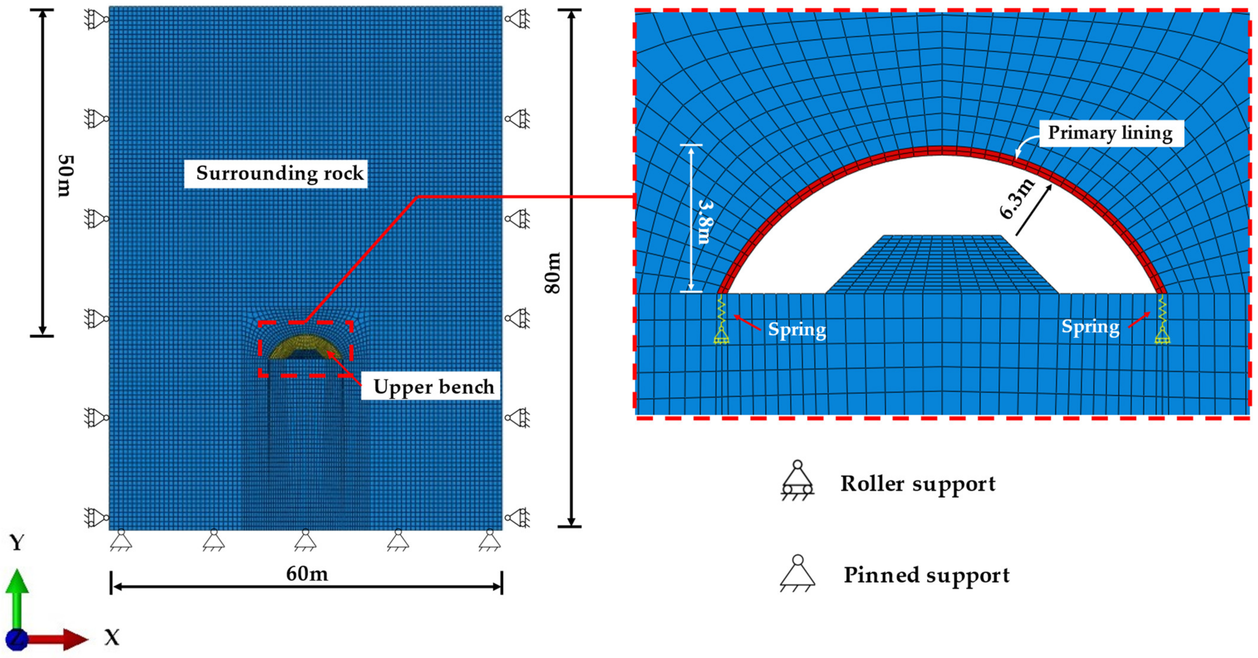
4.1. Numerical Calculation Model
The numerical simulation adopted the finite element software Abaqus. The excavation height of the upper bench was 3.8 m, the radius of the arc segment was 6.3 m, and the primary lining thickness was 0.24 m. In order to reduce the influence of the boundary on the calculation results, the overall model width (x-direction) was 60 m, the height (y-direction) was 80 m, and the top of the tunnel was 50 m from the free surface. The left and right of the model constrained the horizontal displacement, and the bottom constrained the horizontal and vertical displacement. The numerical model size and meshing are shown in
Figure 12.
The elastic–plastic model based on the Mohr–Coulomb strength criterion was adopted for the soil mass. The primary lining included C25 concrete, an I20b steel arch, and FLSP, which adopted the elastic model. The steel arch’s stiffness was transferred into the primary lining through stiffness conversion [
19]. The plane strain element CPE4 was adopted for the primary lining and surrounding rock. The spring element simulated the FLSP. The spring and the primary lining were connected by node coupling. Common nodes were adopted to connect the primary lining and surrounding rock. The material parameters are shown in
Table 2.
Equations (6) and (7) give the load–displacement relationship and the lateral stiffness of the connection part (point O in
Figure 2) between the FLSP and the initial support, respectively. In order to facilitate the selection design and the realization of active bearing, the FLSP was simplified as a spring in the numerical simulation. The bottom of the spring was fixed, the upper part of the spring was coupled and connected to the lower end of the primary lining, and the active bearing effect of the foot-locking steel pipe could be achieved by pre-compressing the spring or setting a nonlinear spring.
4.2. Optimal Selection Analysis of FLSP
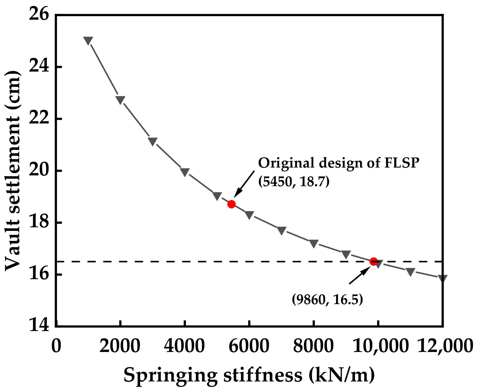
The numerical simulation results used to obtain the relationship curve between the vault settlement and the spring stiffness are summarized in
Figure 13. It can be seen from the figure that the vault settlement decreased gradually with the increase in spring stiffness, indicating that the bearing force provided by the FLSP increased gradually. Under the no-spring condition, the vault settlement was greater than the control settlement value of 16.5 cm, so it was necessary to restrict and control the settlement of the arch vault with the FLSPs. The original design adopted four ϕ42 × 4 mm FLSPs. Because the corresponding spring stiffness was 4088 kN/m, and the steel arch spacing was 75 cm, the corresponding stiffness in the plane model was 5450 kN/m. The corresponding vault settlement calculated by the numerical simulation was 18.7 cm more than the vault settlement control value. Therefore, it was necessary to optimize the design of the FLSP. As can be seen in
Figure 11, when the vault settlement was 16.5 cm, the corresponding spring stiffness was approximately 9860 KN/m, and the required stiffness of FLSP for each steel arch frame was 7400 kN/m.
FLSPs with diameters of 42 mm, 50 mm, 89 mm, and 108 mm, and wall thicknesses of 2 mm, 3 mm, 4 mm, and 5 mm were taken as examples for selection. The reaction coefficient of the surrounding rock foundation was 150 MPa/m. The corresponding lateral stiffness was obtained from Formula (7) and the material parameter calculation, as shown in
Table 4. The design was based on the requirement that the total lateral stiffness of the FLSP should be not less than 7400 kN/m. At the same time, in combination with the steel consumption, the passive bearing scheme of the design optimization method selected two Φ108 × 3 mm FLSPs.
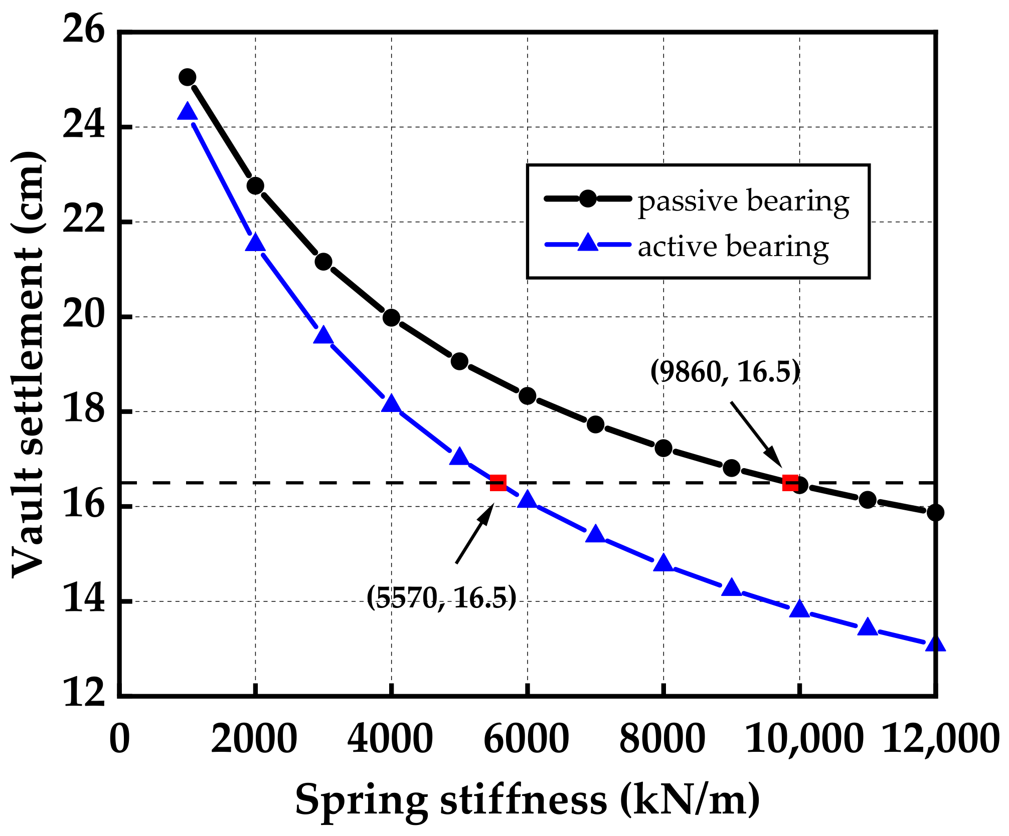
4.3. Analysis of Active Bearing Effect
The vault settlements with different lateral stiffnesses were calculated when the spring was preloaded by 5 cm. The curve is shown in
Figure 14. The effects of the active and passive bearing schemes were compared and analyzed. The change in the two schemes was the same, but the vault settlement was significantly reduced after preloading. With the increase in stiffness, the effect of the controlling settlement was more apparent. When the preload was 5 cm, the spring stiffness corresponding to the vault settlement of 16.5 cm was approximately 5570 kN/m, so the required stiffness of the FLSP was 4180 kN/m. Installing one ϕ108 × 4-millimeter FLSP can meet the settlement control requirements. The passive bearing scheme needs to install two ϕ108 × 3-millimeter FLSPs. According to
Table 1, the steel consumption of the passive bearing scheme is 54.4 kg, and the steel consumption of the active bearing scheme is only 35.9 kg, which reduces the steel consumption by 34%. As a result, the active bearing can significantly reduce the amount of steel and reduce the project cost.
4.4. Monitoring and Measurement Results
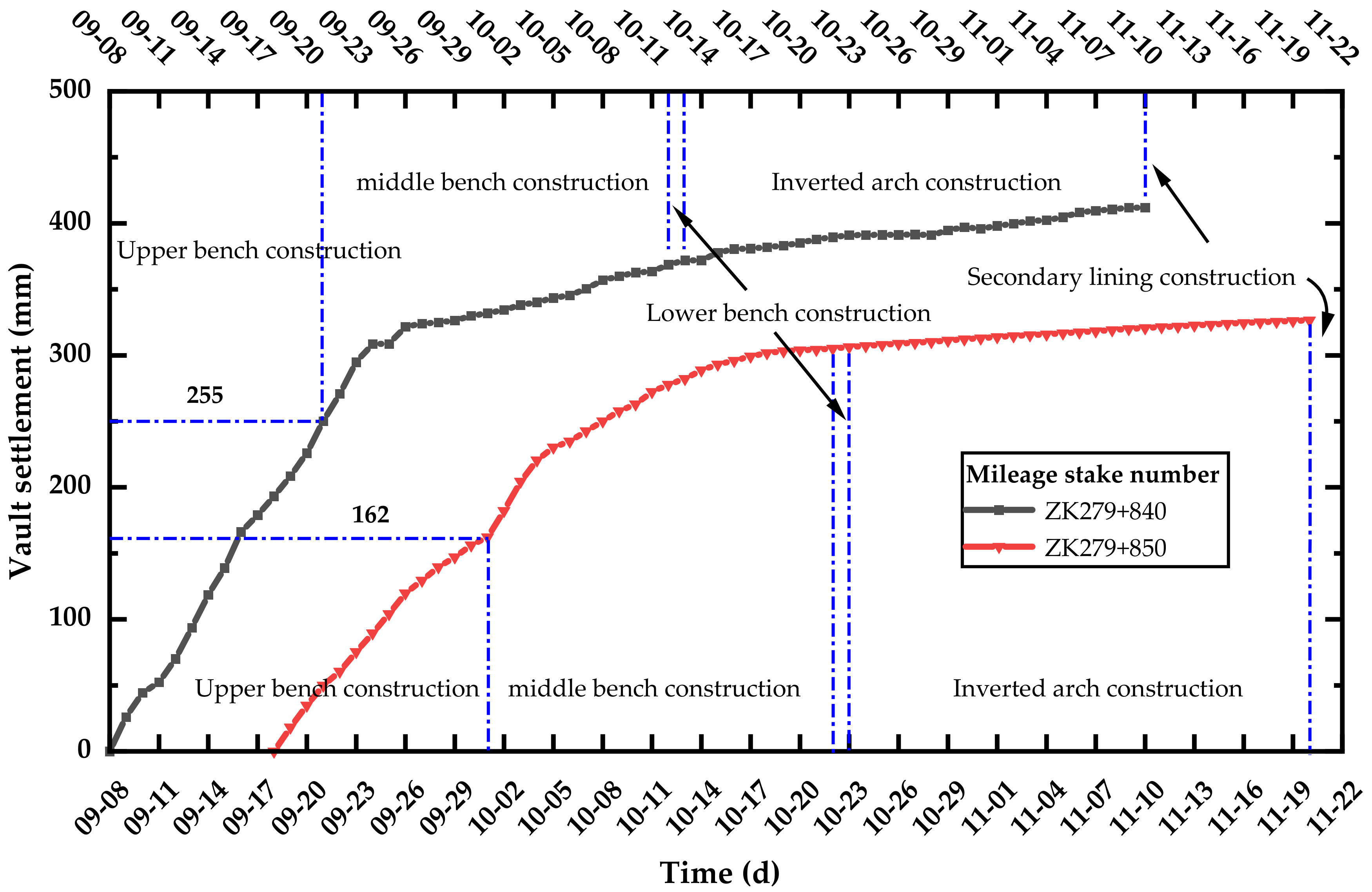
According to the monitoring and measurement, the vault settlement results before and after the design were compared to verify the feasibility of the FLSP design method. In
Figure 15, the time-history curve of the vault settlement is given, in which the section of mileage stake number ZK279 + 840 adopts the original design of four ϕ42 × 4 millimeter FLSPs, and the ZK279 + 850 section adopts two Φ108 × 3-millimeter FLSPs.
The vault settlement of the ZK279 + 840 section was 25.5 cm after the upper bench construction and increased to 41.2 cm before the construction of secondary lining, exceeding the reserved deformation of the tunnel. Through the optimized design of the FLSP, the vault settlement of the ZK279 + 840 section was 16.2 cm after the upper bench construction. It increased to 32.6 cm before the construction of the secondary lining, which was roughly the same as the reserved deformation.
The numerical simulation results show that the vault settlement after the upper bench excavation on the ZK279 + 840 section was 18.7 cm, and that of the ZK279 + 850 section was 16.1 cm. The actual settlement of the ZK279 + 840 section was 25.5 cm, which was larger than the numerical simulation results. The actual settlement of the ZK279 + 850 section was 16.2 cm, which was roughly the same as the numerical simulation. On the one hand, the stress release rates of different sections are different; on the other hand, when the deformation of the loess tunnel is too large, the soil layer loses its bearing capacity, resulting in unpredictable loosening pressure.
From the analysis of the monitoring and measurement results, it can be seen that through the optimized design, the FLSP can control the settlement of the vault within the specified range, showing the feasibility of this method of design optimization.
5. Conclusions
- (1)
The interaction between the FLSP and the primary lining was simplified as a pair of shear forces. The Winkler model was used to analyze the load-deformation characteristics of the FLSP under the condition of shear force. Analyzing the deformation of the FLSP under specific load conditions and the deformation of the primary lining under specific bearing capacity conditions revealed the problem that the deformation of FLSP and the primary lining was inconsistent under particular load and bearing capacities.
- (2)
Under the two working conditions of predicted large deformation and observed large deformation, a design and optimization method for FLSPs based on the load-deformation coordination was proposed. The design method includes four parts: the extraction of the vault settlement control index, the simplification and stiffness calculation of FLSP, the finite element analysis of the primary lining, and the selection of FLSP.
- (3)
For the Yulinzi Tunnel, after the design optimization method, using the passive bearing scheme, two 3.5-m-long ϕ108 × 3-millimeter FLSPs were installed, whereas, for the active bearing scheme, only one ϕ108 × 4-millimeter FLSP needed to be installed when preloaded by 5 cm. The active bearing of the FLSP can significantly reduce the amount of steel required and reduce the engineering cost.
In this study, an optimal design method for FLSPs was proposed. The design method adopts the Winkler model to consider the interaction between FLSP and the soil. Because the small deformation assumption is used in the derivation, only the elastic phase of the FLSP is considered. Next, the design method can be further improved by considering the plasticity of FLSP. The elastic–plastic solution of the deformation of FLSP can be obtained through the theoretical model, or the plasticity of FLSP can be considered through a numerical simulation. On the other hand, this study proposes the active bearing design of FLSPs, but it has not been applied in actual engineering works.
Author Contributions
Conceptualization, Y.W.; methodology, Y.W.; validation, C.T.; investigation, J.Z.; resources, Z.Z.; data curation, J.Z.; writing—original draft preparation, C.T.; writing—review and editing, P.X.; visualization, S.W.; project administration, Z.Z., and S.W.; funding acquisition, Z.Z. All authors have read and agreed to the published version of the manuscript.
Funding
This research was funded by the China Railway Corporation Science and Technology Research and Development Program, grant number 2018K019.
Institutional Review Board Statement
Not applicable.
Informed Consent Statement
Not applicable.
Data Availability Statement
All data are available from the author.
Conflicts of Interest
The authors declare no conflict of interest.
References
- Keawsawasvong, S.; Ukritchon, B. Design equations for the stability of shallow unlined circular tunnels in the Hoek-Brown rock mass. Bull. Eng. Geol. Environ. 2020, 79, 4167–4190. [Google Scholar] [CrossRef]
- Yodsomjai, W.; Keawsawasvong, S.; Likitlersuang, S. Stability of unsupported conical slopes in the Hoek-Brown rock mass. Trans. Infrastructure. Geotechnical. 2021, 8, 279–295. [Google Scholar] [CrossRef]
- Wu, Y.; Lu, K.C.; Xu, Y. Bearing behaviors of steel foot pipes for tunnels in soft foundation. Chin. J. Geotech. Eng. 2009, 31, 1825–1832. (In Chinese) [Google Scholar]
- Luo, Y.B.; Chen, J.X. Mechanical characteristics and mechanical calculation model of tunnel feet-lock bolt in soft surrounding rock. Chin. J. Geotech. Eng. 2013, 35, 1519–1525. (In Chinese) [Google Scholar]
- Li, P.F.; Zhao, Y.; Zhou, X.J. Displacement characteristics of high-speed railway tunnel construction in loess ground by using multi-step excavation method. Tunn. Undergr. Space Technol. 2016, 51, 41–55. [Google Scholar] [CrossRef]
- Fang, Q.; Zhang, D.L.; Wong, L.N.Y. Shallow tunnelling method (STM) for subway station construction in soft ground. Tunn. Undergr. Space Technol. 2012, 29, 10–30. [Google Scholar] [CrossRef]
- Luo, Y.B.; Chen, J.X.; Huang, P.; Tang, M.Q.; Qiao, X.; Liu, Q. Deformation and mechanical model of temporary support sidewall in tunnel cutting partial section. Tunn. Undergr. Space Technol. 2017, 61, 40–49. [Google Scholar] [CrossRef]
- Chen, L.J.; Chen, J.X.; Li, Y.; Luo, Y.B.; Mu, Y.J.; Hu, T.T.; Wang, C.W. Performance of Tunnel Feet-Lock Pipe (TFP) in Sharing Vertical Foundation Load. KSCE J. Civ. Eng. 2021, 25, 1086–1094. [Google Scholar] [CrossRef]
- Chen, L.J.; Zhang, Y.L.; Ma, Z.Y. Analytical approach for support mechanism of feet-lock pipe combined with steel frame in weak rock tunnels. KSCE J. Civ. Eng. 2016, 20, 2965–2980. [Google Scholar] [CrossRef]
- Liang, H.; Wang, Y.; Yan, X.; Liu, J.; Peng, H.; Guo, X. Research on mechanical stability of feet-lock pipe and steel arch in soft rock tunnel. J. Beijing Jiaotong Univ. 2020, 44, 34–41. (In Chinese) [Google Scholar]
- Chen, L.J.; Chen, J.X.; Luo, Y.B.; Li, Y.; Hu, T.T. Vertical load and settlement at the foot of steel rib with the support of feet-lock pipe in soft ground tunnel. Adv. Civ. Eng. 2019, 2019, 6186748. [Google Scholar] [CrossRef] [Green Version]
- Cui, Y.; Kishida, K.; Kimura, M. Analytical Study on the Control of Land Subsidence Accompanying Subsidence Phenomena with Foot Reinforced Side Pile. In Proceedings of the GeoShanghai International Conference 2010, Shanghai, China, 3 June 2010. [Google Scholar]
- Deng, G.; Shao, S.; Tao, H.; Chen, C. A study of the effects of locking tremies on the internal force of tunnel support and the deformation of surrounding soil. Chin. Civil. Eng. J. 2010, 43, 108–113. (In Chinese) [Google Scholar]
- Cui, Y.; Kishida, K.; Kimura, M. Prevention of the ground subsidence by using the foot reinforcement side pile during the shallow overburden tunnel excavation in unconsolidated ground. Tunn. Undergr. Space Technol. 2017, 63, 194–204. [Google Scholar] [CrossRef] [Green Version]
- Luo, Y.B.; Diao, P.S.; Chen, J.X.; Li, D.; Gou, Y.L.; Qiao, X. New Method of Monitoring Tunnel Feet-Lock Pipe (TFP) Mechanics Using Fiber Bragg Grating (FBG). J. Test Eval. 2018, 48, 3125–3142. [Google Scholar] [CrossRef]
- Shi, Z.; Luo, Y.; Chen, J.; Liu, W.; Yu, H. Field simulation test on mechanical characteristics of feet-lock anchor pipes for soft surrounding rock tunnel. J. Highw. Transp. Res. Dev. 2021, 38, 96–106. (In Chinese) [Google Scholar]
- Deng, X.H.; Xia, D.H.; Wang, R.; Liu, Y.Y. Feet-lock bolt application in cracked surrounding rock tunnels. Geotech. Geol. Eng. 2019, 37, 3423–3434. [Google Scholar] [CrossRef]
- Meng, D.; Tan, Z. Deformation control technology and supporting structure stress of large section loess tunnel. Chin. Civil. Eng. J. 2015, 48, 383–387. (In Chinese) [Google Scholar]
- Gkikas, V.I.; Nomikos, P.P. Primary support design for sequentially excavated tunnel junctions in strain-softening hoek–brown rock mass. Geotech. Geol. Eng. 2021, 39, 1997–2018. [Google Scholar] [CrossRef]
| Publisher’s Note: MDPI stays neutral with regard to jurisdictional claims in published maps and institutional affiliations. |
© 2022 by the authors. Licensee MDPI, Basel, Switzerland. This article is an open access article distributed under the terms and conditions of the Creative Commons Attribution (CC BY) license (https://creativecommons.org/licenses/by/4.0/).


