Communication

Application of the Digital Workflow in Orofacial Orthopedics and Orthodontics: Printed Appliances with Skeletal Anchorage

Department of Orthodontics, University Clinic Düsseldorf, Moorenstrasse 5, 40225 Düsseldorf, Germany
*
Author to whom correspondence should be addressed.
Appl. Sci. 2022, 12(8), 3820; https://doi.org/10.3390/app12083820
Submission received: 28 February 2022 / Revised: 4 April 2022 / Accepted: 6 April 2022 / Published: 10 April 2022
(This article belongs to the Special Issue 3D Printed Materials Dentistry)

Abstract

:
As digital workflows are gaining popularity, novel treatment options have also arisen in orthodontics. By using selective laser melting (SLM), highly customized 3D-printed appliances can be manufactured and combined with preformed components. When combined with temporary anchorage devices (TADs), the advantages of the two approaches can be merged, which might improve treatment efficacy, versatility, and patient comfort. This article summarizes state-of-the-art technologies and digital workflows to design and install 3D-printed skeletally anchored orthodontic appliances. The advantages and disadvantages of digital workflows are critically discussed, and examples for the clinical application of mini-implant and mini-plate borne appliances are demonstrated.

1. Introduction

Digital technologies, such as 3D scanning and printing, have expanded the range of treatment options in various medical disciplines in recent years [1,2,3,4,5]. In dentistry, a wide range of possible implementations have been reported across specialties, including the fields of orofacial orthopedics and orthodontics [6]. In contemporary orthodontics, scanning dental arches for metric analyses or the creation of digital set-ups are routinely performed. A relatively new application is the design and clinical application of individual metal-printed orthodontic appliances [7]. Especially in complex cases, where conventional techniques and preformed devices do not fulfill all requirements, individualized 3D-designed and printed appliances may be advantageous [7,8]. In addition, appliances created using a digital workflow are reported to offer many advantages in terms of patient comfort, treatment efficacy, and predictability [7,8].
As every orthodontic (and orthopedic) force is associated with a reactive force of equal magnitude, orthodontic treatment success necessitates sufficient anchorage to avoid side effects, including undesired tooth movement of dental anchorage units [9,10]. Therefore, orthodontic anchorage is a term for all measures preventing those reactive forces and moments [11]. Typically, either teeth (dental units) or extraoral attachments are used. Extra-anchorage can be achieved by integrating the bone into the resistance unit by means of so-called temporary anchorage devices (TADs). This concept is called skeletal anchorage, and it gained popularity in recent years owing to a reduction in side effects and increased treatment efficacy [8,9,10,12,13,14,15,16,17]. Among the TADs, orthodontic mini-implants are frequently employed due to their ease of application and the favorable cost–benefit ratio [18,19].
In the upper jaw, the anterior palate proved to be the most favorable insertion site with the highest survival rates [15,20,21]. In the mandible, however, mini-implants usually have to be inserted into the alveolar ridge [22,23,24], where failure rates range from 14% to 16% [25,26,27]. The lower success rates were mainly attributed to the reduced bone quality and the proximity to the dental roots. In addition, a risk of root contact or even penetration exists [25,26]. Since mini-implants are inserted between the roots, the extent of possible orthodontic tooth movement is implicitly limited. Mini-implants inserted into the mandibular buccal shelf did not gain much acceptance in most of the countries because of their very low survival rates [27], despite their advantage not to limit tooth movements. Alternatively, the chin below the dental roots was identified as a possible insertion site due to its high bone quantity and quality. Nonetheless, mini-implants are not well-suited for the area, and thus special mini-plates, such as the Mentoplate, were developed [28,29]. These plates can be fixed to the bone using regular osteosynthesis screws, but require a slightly more invasive surgical procedure for insertion and removal, when compared with mini-implants.
TAD-borne appliances are regarded as “non-compliance” devices as patients only need to keep them clean, but are not requested to wear them for a certain amount of hours (they have to wear them 24 h/day) [30]. These appliances also permit longer time intervals between appointments and hence a reduction of the overall chair-time [10,12,31].
The application of digital workflows to design and manufacture TAD-borne appliances appears to be particularly promising. The placement of the mini-implants can be planned, which allows the identification of the optimal insertion position based on digital models and, optionally, using radiographs. Utilizing printed insertion guides [32] or the appliance itself [33] allows for implant insertion and appliance installation in one appointment. Owing to the precise fitting, the risk of screw overloading, and therefore the risk of implant failure, can be reduced [34,35]. However, digital workflows rely on the skills and experience of the operator, and pitfalls exist that can limit the advantages of the digital workflow.
The present article describes a fully digital workflow for the creation of TAD-borne metal printed appliances in orthodontics and orofacial orthopedics. Accordingly, some of the most common printing techniques and materials, possible advantages and disadvantages, and potential sources of error are critically discussed.

2. Digital Workflow: From Intraoral Scan to the Printable Data

2.1. Data Acquisition

A fundamental basis for the digital design of orthodontic appliances is gathering information regarding the intraoral situation including teeth, alveolar ridge, and soft tissues. This can be achieved using intraoral scanning or by employing digitized conventional plaster casts. Some studies found the intraoral scan to be more time-consuming than conventional methods [36,37], whereas others did not observe any significant difference [38]. This might indicate that the practitioners’ level of experience could have a major impact on time efficacy. In addition, several studies underlined a sufficient accuracy and precision of intraoral scans for orthodontic purposes [36,37,38,39]. Further advantages of digital impressions compared to conventional ones include gains in comfort for the patient and a reduced amount of laboratory waste [7,8,37,39].
Data can be stored in various formats. Nonetheless, the Standard Tessellation Language (STL) format was shown to be the smallest common denominator for 3D data exchange between devices and software programs [8,36].

2.2. Digital Appliance Design

In order to design and manufacture an appliance, the intraoral scan generally requires further processing, including mesh repair, hole filling, and removal of invalid data. Usually, a base is added to the dental arch to form a model (Figure 1).
Software tools that enable digital planning range from open-source over freeware to proprietary solutions. Currently, there is great variability in software complexity, sometimes necessitating a steep learning curve.
The computer-aided design of the orthodontic appliances enables the planning of all steps, including the positioning of orthodontic mini-implants (Figure 2) or osteosynthesis screws and the position of shells or attachments. Moreover, functional elements can be adapted, for example, by modifying their shape, adjusting the inclination and tilt of gliding mechanisms, or manipulating the expansion of orthodontic screws. Simulation of planned tooth movements is also possible, enabling clinicians to oversee and predict treatment outcomes. Additionally, communication with technicians is simplified. Groups of teeth required to move in a specific direction can be connected to active elements of the appliance, and comparison of actual with predicted tooth movements enables validation (Figure 3).
When skeletal anchorage is employed, an accurate fit of the digitally planned appliance is fundamental to avoid overloading of the orthodontic implants. One option is to perform data acquisition after implant insertion. Sometimes, scanners show problems recognizing the metallic implants, which can be improved using scanning spray or scan bodies [40]. The other option is to insert the mini-implants upon digital planning through guides and utilize the planned position for the appliance design. Digitally planned insertion guides allow implant and appliance insertion within the same visit [40,41,42,43] (Figure 2). This can also be achieved by using so-called Direct Screws, which are inserted after the adhesive bond of the appliance onto the teeth [33]. As the appliances themselves serve as an insertion aid, no additional guide is needed. When installing a printed Mentoplate with supra-constructions for orthodontic tooth movement, a guided insertion is mandatory to precisely achieve the planned position and ensure the fit of supra-construction and teeth.
Digital positioning of (mini-)implants is an already established process in prosthodontic and orthodontic treatments. For insertion of orthodontic screws in the anterior palate, 3D radiographic images are oftentimes not needed. Nonetheless, radiographs can help to estimate the available bone supply [40,44], and they are indicated in case of palatially displaced teeth, limited bone supply, or pathologies, including clefts (Figure 4). Lateral cephalograms provided a sufficient approximation when compared to cone-beam computed tomography (CBCT) for most of the patients [41,45,46]. In case of displaced teeth, patients with craniofacial anomalies, or in case of insufficient bone height visible on a cephalogram, optimal insertion sites and angles can be identified with the help of 3D radiographs [46]. In case of impacted teeth, the optimal vector for force application may also be incorporated in the digital design based on the information from CBCT [12] (Figure 4B).
The digital design of mini-plates for the chin bone requires a CBCT to enable an accurate fit. The segmented chin may be matched with an intraoral scan to create an appliance with transmucosal extensions. As root localization is clearly visible in the CBCT, damage of (unerupted) teeth or roots during screw insertion can be avoided. It is also possible to shape the surface of the bottom of the device in perfect match with the superficial structure of the bone, ensuring wide and evenly flat contact that might prevent side effects.
If clinicians do not design the appliance themselves, the manufacturing laboratory can send the digital draft of the designed appliance back to the clinician, enabling an easy and fast way to revise it, approve it, and communicate desired changes [7,8,47]. Whereas conventionally manufactured appliances would have to be reproduced in case of breakage or improper fit, digital appliances can be reprinted based on the stored data [7], unless they have already been activated in a non-reproducible way.

2.3. Data Preparation for 3D Printing

Since the printing of three-dimensional structures is achieved by adding and joining two-dimensional layers, it is possible to construct very complex and individual structures [48,49]. Printing potential has very few limitations, making preformed pieces just under certain indications necessary. Small parts with internal hollow spaces and pieces with very high requirements regarding the accuracy of fit, such as tubes, elements with internal mechanics, or orthodontic screws, cannot be printed, but can be added by welding them to the printed framework of the appliance. The possibility to create an appliance adapted to the specific intraoral conditions of a patient, almost independent from standardized preformed parts, also allows manufacturing of customized devices for complex and challenging treatment needs [7,47].
The materials used to print the insertion guides for orthodontic implants have to be biocompatible and sterilizable [40]. A precise fit of the insertion tool within the guide’s sleeves is needed to achieve an accurate insertion of the implants. Only minor discrepancies, especially in the vertical direction, are tolerable [41]. Vertical control can be improved by using insertion instruments facilitating vertical control [40].

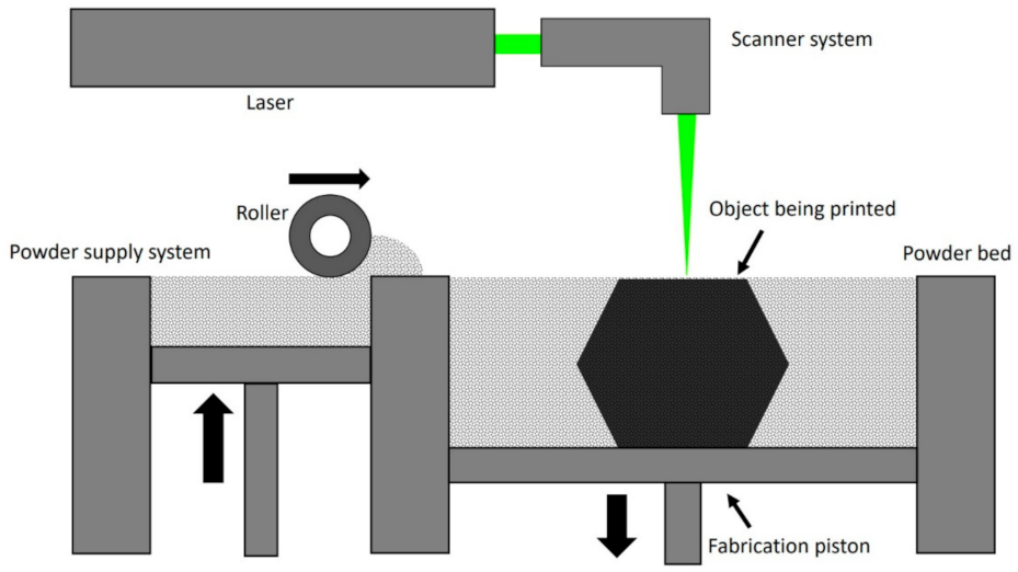
3. 3D Printing Technologies for Orthodontic Appliances

Orthodontic appliances with skeletal anchorage require a metal framework and are usually manufactured by selective laser melting and sintering (SLM/SLS). This additive manufacturing is a kind of solid freeform fabrication and belongs to the powder bed fusion techniques. Since the invention of selective laser sintering (SLS) in 1989 by Carl Deckard, there has been constant progress in the further development of this technique. Using different sources of energy and powdered materials, SLS and SLM can be applied to almost every material melted by laser radiation which solidifies while cooling down, thus making it one of the most versatile additive manufacturing techniques [48,50]. In this technique, a laser emitter moves over a bed of metal powder (e.g., CrCoW) which is heated minimally below its melting point. By tracing the modulated laser over the compacted powder, heat-fusible materials selectively melt in layers. Upon completion of a layer, the powder bed containing the structures being printed is lowered and new material is provided by rolling a thin coating of powder on top (Figure 5).
Modern SLS can produce objects in layers with a thickness of 30–200 µm, depending on the particle size of the powder [49,50]. Once a structure is finished, the remaining powder must be brushed or blown off. Depending on the laser’s power and the used material, the particles are sintered or fully melted together. In SLS, the emitted laser melts the grains’ surface, while the core stays unaffected and solid. This partial melting allows for binding between the grains. Employing higher-powered lasers melts the grains fully to the core, resulting in homogenous structures, which solidify by cooling down [48]. Equipped with highly powered precision lasers, SLM improved many disadvantages of SLS, such as rough surfaces with high porosities and large shrink rates of the produced parts [48,49,50]. On the other hand, complete melting leads to higher surface tensions and therefore requires a smaller thickness of layers [48]. SLM-produced objects demonstrated high accuracy and precision in prosthodontic research, satisfying clinical requirements, sometimes surpassing other methods such as casting or milling [51,52,53,54].
Metal powders used for three-dimensional printing must fulfill all requirements regarding biocompatibility, thus allowing a safe mid- and long-term use in the oral environment. Therefore, alloys certified for oral application are commonly utilized for orthodontic purposes, among which, chromium-cobalt alloys [6,8,51,54,55] and titanium alloys for submucosal placements [48,50,55] are the most popular in orthodontics.
In the post-processing, the surface must be milled to remove all supporting structures as well as the rough outer oxide layer. Since SLS/SLM requires fewer supporting structures, post-processing is eased compared to other additive manufacturing procedures [49] (Figure 6A). If needed, preformed parts such as orthodontic screws, hooks for extraoral gears, or tubes can be added to the device by welding them to the framework (Figure 6B,C). Appliances designed with direct screws also require the matching thread to be welded onto the framework, because its co-axial construction is too complex to be printed.
Auxiliary devices such as insertion guides or models are usually manufactured using printing resin materials. Depending on the purpose and the chosen resin, printing technologies can be divided into light curing and fused deposition modeling (FDM) [6,55]. Photosensitive resins can be printed using specific light-curing techniques called stereolithography (SLA), digital light processing (DLP), and photo jet (PJ). In SLA and DLP, objects are shaped by applying selective UV-light irradiation to a reservoir of liquid resin. The polymerized resin is attached to a platform that moves at defined distances away from the light source, resulting in an incremental shaping of objects similar to the SLM process. In contrast, in PJ technologies, photopolymers are sprayed onto a platform by a horizontally moving print head. The light curing occurs simultaneously through a UV-light-emitting lamp positioned at the print head. Posteriorly, the platform moves away on the Z-axis in the desired amount of layer thickness, shaping the object in incremental layers. In light-curing 3D printers, almost any kind of liquid photopolymers can be used. By applying PJ, printing composites of resins and ceramics is possible. In FDM, objects are shaped by heating thermoplastic materials up to their melting points and printing filaments in layers. Besides conventional thermoplastic materials, biological thermoplasts, such as polylactic acid, polycaprolactone, or acrylonitrile-butadiene-styrene, can be employed in FDM [6,55]. If the printed object will be employed in the oral cavity and may come in direct contact with blood, the material must be sterilized prior to usage and requires the respective certification. Commonly used materials for printed medical devices can be sterilized using ethylene oxide, e-beam, hydrogen peroxide, gamma radiation, or steam sterilization in an autoclave, depending on the chosen polymer [56,57,58,59,60,61] and the national legal requirements. Moreover, a high degree of biocompatibility must be ensured for materials used in the oral cavity, regarding a lack of cytotoxic, sensitizing, or irritational properties.

4. Sources of Error

Printed appliances show very high precision, good fit, and low error rates. Nonetheless, digital workflows and clinical implementation are complex and require specific operational knowledge and exact working methods.
Depending on the chosen workflow and appliance installation mode, there are possible sources of error to be considered. In case that all steps have been accurately performed, guided insertion enables accurate insertion and appliance fits. However, minor errors may accumulate, and in this case implants may show a certain degree of variance from their planned position, resulting in poor congruence and thus requiring an adjustment of the device’s connectors before installation. Position variance may occur due to the plastic guide’s flexibility, if too much pressure forces the drills into a false angulation, or if the time period between the intraoral scan and the appointment of appliance insertion has been too long. In the latter case, the insertion template and the appliance itself can show variation due to a patient’s natural growth or a change in the stage of eruption and tooth position. If the inconsistency between the implants and the connector is too big, tension will be placed on the connection, resulting in patient discomfort, implant overload, and potential implant failure. Nonetheless, the connectors can be minimally widened by using a milling cutter. Additionally, the rigid printing alloys also allow a certain degree of bending, leading to the possibility of readjusting and correcting minor inaccuracies. According to clinical experience, implants inserted into the patient’s palate before the scan without a stabilizing appliance may trigger the patients’ tongues to press against the implants, resulting in manipulation and a possible loss of the implants.
Direct Screw-borne appliances that are fixed onto the teeth prior to the implant insertion usually do not bear the risk of screw overloading or improper fit, as minor angular deviations can be compensated by the appliance. Nonetheless, insertion of the screws through the incorporated guides can generate moments and forces on the whole appliance when locking the screws into the thread of the connector, especially in case of angular discrepancies. This could stress implants and adhesive connections. As a result, the implants may loosen, or the adhesive bonds may weaken. Therefore, maintaining a correct insertion angle is strongly recommended. Similar to conventional appliances, printed metal devices can be subject to fracture or loss of adhesive connections to the teeth. Whereas screw-retained devices can be removed temporarily for repair, fracture of the direct screw-borne appliances may necessitate exchange of the implants whenever no intraoral repair is possible.

5. Clinical Application

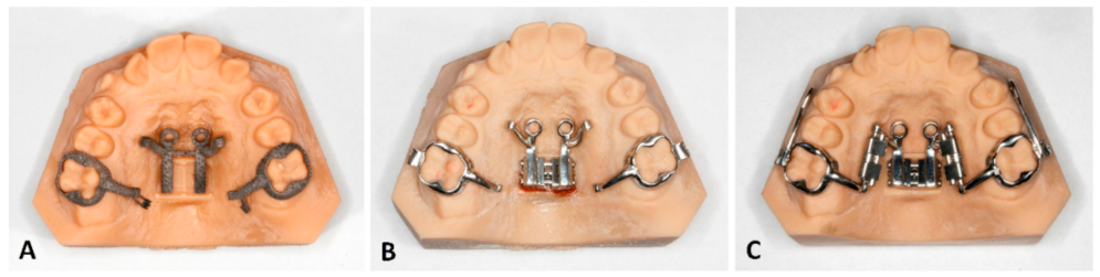
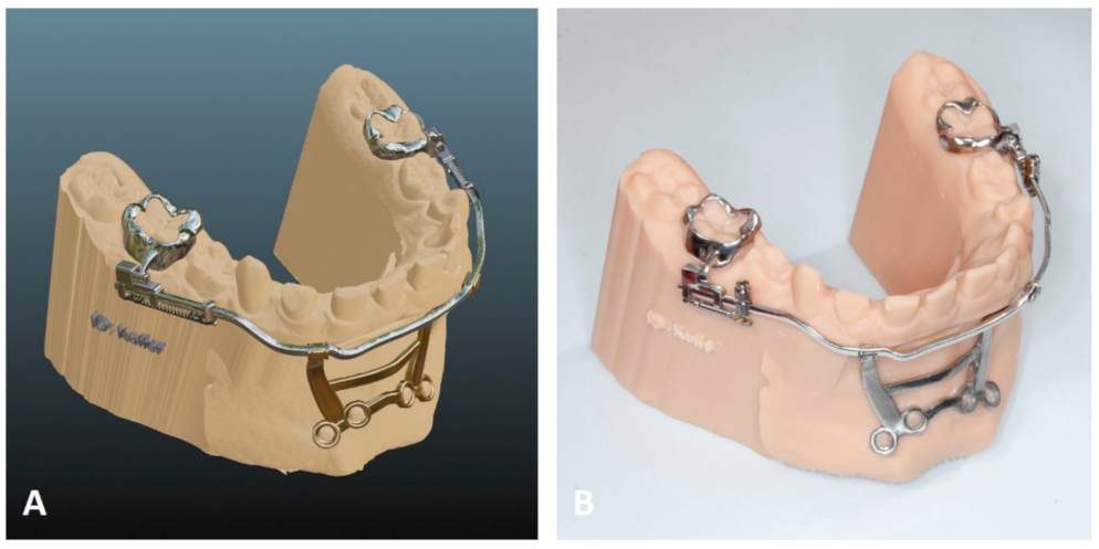
5.1. Temporary Anchorage Device-Borne Appliances

When skeletal anchorage is employed, the non-digital workflow consists of unguided implant insertion, followed by a conventional silicone molding with impression caps. Then, the appliance is manufactured based on a plastered model with laboratory analogs, mainly consisting of preformed components. Once finished, the appliance can be installed unless it does not fit properly.
In contrast, for skeletally anchored appliances manufactured using a digital workflow, the clinician can choose and alter the mode of installation. The appliance can be designed to be fastened onto formerly placed implants, or it can be installed simultaneously with the implants using an insertion guide for the implantation, or it can be attached to the teeth prior to the implantation (Direct Screws). In the latter case, the appliance itself serves as an insertion template [33].
Taking a closer look into the various options of implant installation helps with outlining the respective advantages and disadvantages.
A common way to place an implant-supported appliance into the oral cavity is to set the implants at their determined position using an insertion guide (Figure 7A,B). This ensures a perfect match with the printed appliance (Figure 7C). Fixing the appliance to its skeletal anchor requires a mechanism that locks the appliance on top of the implants and prevents rotations. If a fixation screw is used, adapting the appliance, or changing to a completely different device, is possible [33] (Figure 7D). The adhesive bond between the appliance and teeth occurs before the insertion of the fastening screws.
In case of Direct Screws, the appliance itself serves as the guide [33] (Figure 8). In this case, the practitioner adhesively attaches the appliance to the teeth and then uses the hole of the appliance’s connectors as an insertion aid. This installation method can be advantageous because it eradicates a possible mismatch between implants and the appliance, and eliminates the need for an additional 3D-printed insertion guide.
When implant placement is performed prior to intraoral scanning, appliance installation is performed similar to conventional approaches. In case of immediate loading, one must consider that primary stability of the implants reduces within the first 4–6 weeks after insertion due to a loss of primary stability. Nonetheless, immediate loading of the implants has been reported to be not detrimental or even beneficial in terms of implant stability [62,63].
The molar coupling of digitally printed appliances can be achieved by means of printed shells or palatally attached tubes. These couplings do not penetrate the attached soft tissue and usually remain coronally to the interproximal contacts [64]. It may be speculated that this can lead to higher failure rates, which, however, can be reduced by etching the surface of the teeth and using an adhesive system instead of temporary cement. Additionally, no rubber-based separation of teeth is required prior to appliance insertion [7,65]. The preformed shape of customized, 3D-printed molar shells thus obviates the need to adapt bands, which may increase comfort for both the patient and practitioner [7,40]. Even though limited evidence is available, the digitally printed shells seem to provide clinically acceptable survival rates [7].

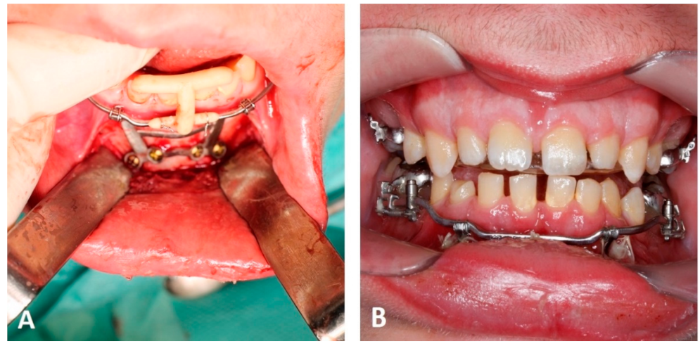
5.2. Computer-Aided Manufactured Mentoplates

Conventional Mentoplates were shown to be effective, especially in case of maxillary protraction in early class III treatments [28,29]. Using computer-aided manufacturing, Mentoplates can be designed to hold supra-constructions with various functional elements of high precision, including sliding mechanics for distalization or mesialization of posterior teeth, which increase the range of treatment options (Figure 9).
Both conventional and digitally manufactured appliances with a submucosal extent can be made from titanium alloys. Under local anesthesia or narcosis, the oral surgeon prepares a mucoperiosteal flap, revealing the bone structures of the chin. Conventional Mentoplates are adapted by bending them manually to fit the chin bone. The two extension arms are shortened and formed either straight or bent into a hook. Depending on the purpose of the treatment, they should penetrate the soft tissue at the mucogingival border or within the attached mucosa to avoid infection and eventually loss of the appliance.
3D-printed appliances do not require adaptation within surgery as they are already customized regarding the individual anatomical situation. While guides for palatal appliances lead the drill during the implants’ insertion, osteosynthesis screws are directly applied into their connectors. Therefore, the guide must stabilize the Mentoplate in the correct position while the screws are inserted. For this purpose, it proved efficient to assemble the Mentoplate with its supra-construction and employ the posterior shells as orientation. To achieve stable triangular support, a printed guide can be mounted onto the lower incisors as well as on the supra-construction, ensuring vertical control (Figure 10). After fastening the screws, the guide can be removed, and the active elements can be adjusted as indicated. After the screws are applied, the flap can be adapted and sutured.

6. Conclusions

The incorporation of a digital workflow with computer-aided design enabled fabrication of customized 3D-printed metal orthodontic appliances. In complex cases requiring additional anchorage, the incorporation of skeletal anchorage may increase the spectrum of treatment options and enable highly time-efficient treatments with increased patient comfort. Nonetheless, digital workflows necessitate an initial training period and may be associated with high acquisition costs, especially when applied in-house. As errors during the process can accumulate from the different steps, accurate planning and validation of a proper fit prior to insertion of screws and appliances is strongly recommended.

Author Contributions

Conceptualization, M.K. and K.B.; software, D.D.; investigation, M.K. and K.B.; resources, D.D.; writing—original draft preparation, M.K.; writing—review and editing, M.K., D.D. and K.B.; visualization, M.K. and K.B.; supervision, M.K., D.D. and K.B.; project administration, M.K., D.D. and K.B. All authors have read and agreed to the published version of the manuscript.

Funding

This research received no external funding.

Informed Consent Statement

Written informed consent has been obtained from the patients to publish this paper.

Data Availability Statement

Not applicable.

Conflicts of Interest

The authors declare no conflict of interest.

References

  1. Wong, K.C. 3D-printed patient-specific applications in orthopedics. Orthop. Res. Rev. 2016, 8, 57–66. [Google Scholar] [CrossRef] [PubMed] [Green Version]
  2. Tack, P.; Victor, J.; Gemmel, P.; Annemans, L. 3D-printing techniques in a medical setting: A systematic literature review. Biomed. Eng. Online 2016, 15, 115. [Google Scholar] [CrossRef] [PubMed] [Green Version]
  3. Bauermeister, A.J.; Zuriarrain, A.; Newman, M.I. Three-Dimensional Printing in Plastic and Reconstructive Surgery: A Systematic Review. Ann. Plast. Surg. 2016, 77, 569–576. [Google Scholar] [CrossRef] [PubMed]
  4. Jamróz, W.; Szafraniec, J.; Kurek, M.; Jachowicz, R. 3D Printing in Pharmaceutical and Medical Applications—Recent Achievements and Challenges. Pharm. Res. 2018, 35, 176. [Google Scholar] [CrossRef] [PubMed] [Green Version]
  5. Della Bona, A.; Cantelli, V.; Britto, V.T.; Collares, K.F.; Stansbury, J.W. 3D printing restorative materials using a stereolithographic technique: A systematic review. Dent. Mater. 2021, 37, 336–350. [Google Scholar] [CrossRef]
  6. Tian, Y.; Chen, C.; Xu, X.; Wang, J.; Hou, X.; Li, K.; Lu, X.; Shi, H.; Lee, E.S.; Jiang, H.B. A Review of 3D Printing in Dentistry: Technologies, Affecting Factors, and Applications. Scanning 2021, 2021, 9950131. [Google Scholar] [CrossRef]
  7. Graf, S.; Cornelis, M.A.; Hauber Gameiro, G.; Cattaneo, P.M. Computer-aided design and manufacture of hyrax devices: Can we really go digital? Am. J. Orthod. Dentofac. Orthop. 2017, 152, 870–874. [Google Scholar] [CrossRef] [Green Version]
  8. Graf, S.; Vasudavan, S.; Wilmes, B. CAD-CAM design and 3-dimensional printing of mini-implant retained orthodontic appliances. Am. J. Orthod. Dentofac. Orthop. 2018, 154, 877–882. [Google Scholar] [CrossRef] [Green Version]
  9. Clemente, R.; Contardo, L.; Greco, C.; Di Lenarda, R.; Perinetti, G. Class III Treatment with Skeletal and Dental Anchorage: A Review of Comparative Effects. BioMed Res. Int. 2018, 2018, 7946019. [Google Scholar] [CrossRef]
  10. Wilmes, B.; Olthoff, G.; Drescher, D. Comparison of skeletal and conventional anchorage methods in conjunction with pre-operative decompensation of a skeletal class III malocclusion. J. Orofac. Orthop. 2009, 70, 297–305. [Google Scholar] [CrossRef]
  11. Proffit, W.R.; Fields, H.W. Contemporary Orthodontics; Mosby-Year Book: St. Louis, MO, USA, 1993. [Google Scholar]
  12. Nienkemper, M.; Wilmes, B.; Lübberink, G.; Ludwig, B.; Drescher, D. Extrusion of impacted teeth using mini-implant mechanics. J. Clin. Orthod. 2012, 46, 150–155, quiz 183. [Google Scholar] [PubMed]
  13. Nienkemper, M.; Handschel, J.; Drescher, D. Systematic review of mini-implant displacement under orthodontic loading. Int. J. Oral Sci. 2014, 6, 1–6. [Google Scholar] [CrossRef] [PubMed] [Green Version]
  14. Wilmes, B.; Willmann, J.; Stocker, B.; Drescher, D. Mini-Implantate zur kieferorthopädischen Verankerung im anterioren Gaumen, mediane vs. paramediane Insertion. Inf. Orthod. Kieferorthopädie 2015, 47, 243–248. [Google Scholar] [CrossRef]
  15. Wilmes, B.; Ludwig, B.; Vasudavan, S.; Nienkemper, M.; Drescher, D. The T-Zone: Median vs. Paramedian Insertion of Palatal Mini-Implants. J. Clin. Orthod. 2016, 50, 543–551. [Google Scholar]
  16. Becker, K.; Pliska, A.; Busch, C.; Wilmes, B.; Wolf, M.; Drescher, D. Efficacy of orthodontic mini implants for en masse retraction in the maxilla: A systematic review and meta-analysis. Int. J. Implant. Dent. 2018, 4, 35. [Google Scholar] [CrossRef] [PubMed]
  17. Becker, K.; Wilmes, B.; Grandjean, C.; Vasudavan, S.; Drescher, D. Skeletally anchored mesialization of molars using digitized casts and two surface-matching approaches: Analysis of treatment effects. J. Orofac. Orthop. 2018, 79, 11–18. [Google Scholar] [CrossRef]
  18. Fritz, U.; Ehmer, A.; Diedrich, P. Clinical suitability of titanium microscrews for orthodontic anchorage-preliminary experiences. J. Orofac. Orthop. 2004, 65, 410–418. [Google Scholar] [CrossRef]
  19. Wilmes, B.; Drescher, D. A miniscrew system with interchangeable abutments. J. Clin. Orthod. 2008, 42, 574–580. [Google Scholar]
  20. Ludwig, B.; Glasl, B.; Bowman, S.J.; Wilmes, B.; Kinzinger, G.S.M.; Lisson, J.A. Anatomical guidelines for miniscrew insertion: Palatal sites. J. Clin. Orthod. 2011, 45, 433–441. [Google Scholar]
  21. Mohammed, H.; Wafaie, K.; Rizk, M.Z.; Almuzian, M.; Sosly, R.; Bearn, D.R. Role of anatomical sites and correlated risk factors on the survival of orthodontic miniscrew implants: A systematic review and meta-analysis. Prog. Orthod. 2018, 19, 36. [Google Scholar] [CrossRef] [Green Version]
  22. Nienkemper, M.; Pauls, A.; Ludwig, B.; Wilmes, B.; Drescher, D. Preprosthetic molar uprighting using skeletal anchorage. J. Clin. Orthod. 2013, 47, 433–437. [Google Scholar] [PubMed]
  23. Ludwig, B.; Glasl, B.; Kinzinger, G.S.M.; Lietz, T.; Lisson, J.A. Anatomical guidelines for miniscrew insertion: Vestibular interradicular sites. J. Clin. Orthod. 2011, 45, 165–173. [Google Scholar]
  24. Poggio, P.M.; Incorvati, C.; Velo, S.; Carano, A. “Safe zones”: A guide for miniscrew positioning in the maxillary and mandibular arch. Angle Orthod. 2006, 76, 191–197. [Google Scholar]
  25. Chen, Y.H.; Chang, H.H.; Chen, Y.J.; Lee, D.; Chiang, H.H.; Yao, C.C. Root contact during insertion of miniscrews for orthodontic anchorage increases the failure rate: An animal study. Clin. Oral Implant. Res. 2008, 19, 99–106. [Google Scholar] [CrossRef] [PubMed]
  26. Kadioglu, O.; Büyükyilmaz, T.; Zachrisson, B.U.; Maino, B.G. Contact damage to root surfaces of premolars touching miniscrews during orthodontic treatment. Am. J. Orthod. Dentofac. Orthop. 2008, 134, 353–360. [Google Scholar] [CrossRef]
  27. Arqub, S.A.; Gandhi, V.; Mehta, S.; Palo, L.; Upadhyay, M.; Yadav, S. Survival estimates and risk factors for failure of palatal and buccal mini-implants. Angle Orthod. 2021, 91, 756–763. [Google Scholar] [CrossRef]
  28. Wilmes, B.; Nienkemper, M.; Ludwig, B.; Kau, C.H.; Drescher, D. Early Class III treatment with a hybrid hyrax-mentoplate combination. J. Clin. Orthod. 2011, 45, 15–21. [Google Scholar]
  29. Katyal, V.; Wilmes, B.; Nienkemper, M.; Darendeliler, M.A.; Sampson, W.; Drescher, D. The efficacy of Hybrid Hyrax-Mentoplate combination in early Class III treatment: A novel approach and pilot study. Aust. Orthod. J. 2016, 32, 88–96. [Google Scholar] [CrossRef]
  30. Freudenthaler, J.W.; Haas, R.; Bantleon, H.P. Bicortical titanium screws for critical orthodontic anchorage in the mandible: A preliminary report on clinical applications. Clin. Oral Implants Res. 2001, 12, 358–363. [Google Scholar] [CrossRef]
  31. Nienkemper, M.; Pauls, A.; Ludwig, B.; Wilmes, B.; Drescher, D. Multifunctional use of palatal mini-implants. J. Clin. Orthod. 2012, 46, 679–686. [Google Scholar]
  32. Becker, K.; de Gabriele, R.; Dallatana, G.; Trelenberg-Stoll, V.; Wilmes, B.; Drescher, D. 3-D-Planung für Implantate in der Kieferorthopädie; Quintessence Publishing: Berlin, Germany, 2018; pp. 147–154. [Google Scholar]
  33. Willmann, J.; Wilmes, B.; Becker, K.; Drescher, D. Hybrid Hyrax Direct. Kieferorthopädie 2020, 34, 249–257. [Google Scholar]
  34. Isidor, F. Histological evaluation of peri-implant bone at implants subjected to occlusal overload or plaque accumulation. Clin. Oral Implants Res. 1997, 8, 1–9. [Google Scholar] [CrossRef] [PubMed]
  35. Isidor, F. Loss of osseointegration caused by occlusal load of oral implants. A clinical and radiographic study in monkeys. Clin. Oral Implants Res. 1996, 7, 143–152. [Google Scholar] [CrossRef] [PubMed]
  36. Jedliński, M.; Mazur, M.; Grocholewicz, K.; Janiszewska-Olszowska, J. 3D Scanners in Orthodontics-Current Knowledge and Future Perspectives—A Systematic Review. Int. J. Environ. Res. Public Health 2021, 18, 1121. [Google Scholar] [CrossRef]
  37. Aragón, M.L.; Pontes, L.F.; Bichara, L.M.; Flores-Mir, C.; Normando, D. Validity and reliability of intraoral scanners compared to conventional gypsum models measurements: A systematic review. Eur. J. Orthod. 2016, 38, 429–434. [Google Scholar] [CrossRef] [PubMed]
  38. Glisic, O.; Hoejbjerre, L.; Sonnesen, L. A comparison of patient experience, chair-side time, accuracy of dental arch measurements and costs of acquisition of dental models. Angle Orthod. 2019, 89, 868–875. [Google Scholar] [CrossRef] [Green Version]
  39. Groth, C.; Kravitz, N.D.; Jones, P.E.; Graham, J.W.; Redmond, W.R. Three-dimensional printing technology. J. Clin. Orthod. 2014, 48, 475–485. [Google Scholar]
  40. Willmann, J.H.; Wilmes, B.; Chhatwani, S.; Drescher, D. Klinische Anwendung des digitalen Workflows am Beispiel von Mini-Implantaten. Inf. Orthod. Kieferorthopädie 2020, 52, 121–127. [Google Scholar] [CrossRef]
  41. Möhlhenrich, S.C.; Brandt, M.; Kniha, K.; Bock, A.; Prescher, A.; Hölzle, F.; Modabber, A.; Danesh, G. Suitability of virtual plaster models superimposed with the lateral cephalogram for guided paramedian orthodontic mini-implant placement with regard to the bone support. J. Orofac. Orthop. 2020, 81, 340–349. [Google Scholar] [CrossRef]
  42. Kniha, K.; Brandt, M.; Bock, A.; Modabber, A.; Prescher, A.; Hölzle, F.; Danesh, G.; Möhlhenrich, S.C. Accuracy of fully guided orthodontic mini-implant placement evaluated by cone-beam computed tomography: A study involving human cadaver heads. Clin. Oral Investig. 2021, 25, 1299–1306. [Google Scholar] [CrossRef]
  43. Gabriele, O.; Dallatana, G.; Riva, R.; Vasudavan, S.; Wilmes, B. The easy driver for placement of palatal mini-implants and a maxillary expander in a single appointment. J. Clin. Orthod. JCO 2017, 51, 728–737. [Google Scholar] [PubMed]
  44. Petzold, R.; Zeilhofer, H.F.; Kalender, W.A. Rapid protyping technology in medicine-basics and applications. Comput. Med. Imaging Graph. 1999, 23, 277–284. [Google Scholar] [CrossRef]
  45. Möhlhenrich, S.C.; Brandt, M.; Kniha, K.; Prescher, A.; Hölzle, F.; Modabber, A.; Wolf, M.; Peters, F. Accuracy of orthodontic mini-implants placed at the anterior palate by tooth-borne or gingiva-borne guide support: A cadaveric study. Clin. Oral Investig. 2019, 23, 4425–4431. [Google Scholar] [CrossRef] [PubMed]
  46. Jung, B.A.; Wehrbein, H.; Heuser, L.; Kunkel, M. Vertical palatal bone dimensions on lateral cephalometry and cone-beam computed tomography: Implications for palatal implant placement. Clin. Oral Implants Res. 2011, 22, 664–668. [Google Scholar] [CrossRef] [PubMed]
  47. Graf, S.; Tarraf, N.E.; Kravitz, N.D. Three-dimensional metal printed orthodontic laboratory appliances. Semin. Orthod. 2021, 27, 189–193. [Google Scholar] [CrossRef]
  48. Mazzoli, A. Selective laser sintering in biomedical engineering. Med. Biol. Eng. Comput. 2013, 51, 245–256. [Google Scholar] [CrossRef]
  49. Mazzoli, A.; Germani, M.; Moriconi, G. Application of optical digitizing techniques to evaluate the shape accuracy of anatomical models derived from computed tomography data. J. Oral Maxillofac. Surg. 2007, 65, 1410–1418. [Google Scholar] [CrossRef]
  50. Gokuldoss, P.K.; Kolla, S.; Eckert, J. Additive Manufacturing Processes: Selective Laser Melting, Electron Beam Melting and Binder Jetting-Selection Guidelines. Materials 2017, 10, 672. [Google Scholar] [CrossRef] [Green Version]
  51. Al Maaz, A.; Thompson, G.A.; Drago, C.; An, H.; Berzins, D. Effect of finish line design and metal alloy on the marginal and internal gaps of selective laser melting printed copings. J. Prosthet. Dent. 2019, 122, 143–151. [Google Scholar] [CrossRef]
  52. Presotto, A.G.C.; Barão, V.A.R.; Bhering, C.L.B.; Mesquita, M.F. Dimensional precision of implant-supported frameworks fabricated by 3D printing. J. Prosthet. Dent. 2019, 122, 38–45. [Google Scholar] [CrossRef]
  53. Akçin, E.T.; Güncü, M.B.; Aktaş, G.; Aslan, Y. Effect of manufacturing techniques on the marginal and internal fit of cobalt-chromium implant-supported multiunit frameworks. J. Prosthet. Dent. 2018, 120, 715–720. [Google Scholar] [CrossRef] [PubMed]
  54. Bae, S.; Hong, M.H.; Lee, H.; Lee, C.H.; Hong, M.; Lee, J.; Lee, D.H. Reliability of Metal 3D Printing with Respect to the Marginal Fit of Fixed Dental Prostheses: A Systematic Review and Meta-Analysis. Materials 2020, 13, 4781. [Google Scholar] [CrossRef] [PubMed]
  55. Lin, L.; Fang, Y.; Liao, Y.; Chen, G.; Gao, C.; Zhu, P. 3D printing and digital processing techniques in dentistry: A review of literature. Adv. Eng. Mater. 2019, 21, 1801013. [Google Scholar] [CrossRef]
  56. Tipnis, N.P.; Burgess, D.J. Sterilization of implantable polymer-based medical devices: A review. Int. J. Pharm. 2018, 544, 455–460. [Google Scholar] [CrossRef]
  57. Jeremy, W.; Thampi, R.; Marc, L.; Michael, K.; Quan, N. Sterilization of bedside 3D-printed devices for use in the operating room. Ann. 3D Print. Med. 2022, 5, 100045. [Google Scholar]
  58. Ghobeira, R.; Philips, C.; Declercq, H.; Cools, P.; De Geyter, N.; Cornelissen, R.; Morent, R. Effects of different sterilization methods on the physico-chemical and bioresponsive properties of plasma-treated polycaprolactone films. Biomed. Mater. 2017, 12, 015017. [Google Scholar] [CrossRef] [Green Version]
  59. Sharma, N.; Cao, S.; Msallem, B.; Kunz, C.; Brantner, P.; Honigmann, P.; Thieringer, F.M. Effects of Steam Sterilization on 3D Printed Biocompatible Resin Materials for Surgical Guides-An Accuracy Assessment Study. J. Clin. Med. 2020, 9, 1506. [Google Scholar] [CrossRef]
  60. Toro, M.; Cardona, A.; Restrepo, D.; Buitrago, L. Does vaporized hydrogen peroxide sterilization affect the geometrical properties of anatomic models and guides 3D printed from computed tomography images? 3D Print Med. 2021, 7, 29. [Google Scholar] [CrossRef]
  61. Pérez Davila, S.; González Rodríguez, L.; Chiussi, S.; Serra, J.; González, P. How to Sterilize Polylactic Acid Based Medical Devices? Polymers 2021, 13, 2115. [Google Scholar] [CrossRef]
  62. Melsen, B.; Costa, A. Immediate loading of implants used for orthodontic anchorage. Clin. Orthod. Res. 2000, 3, 23–28. [Google Scholar] [CrossRef]
  63. Rismanchian, M.; Raji, S.H.; Razavi, S.M.; Rick, D.T.; Davoudi, A. Application of Orthodontic Immediate Force on Dental Implants: Histomorphologic and Histomorphometric Assessment. Ann. Maxillofac. Surg. 2017, 7, 11–17. [Google Scholar] [PubMed]
  64. Rossini, G.; Parrini, S.; Castroflorio, T.; Deregibus, A.; Debernardi, C.L. Diagnostic accuracy and measurement sensitivity of digital models for orthodontic purposes: A systematic review. Am. J. Orthod. Dentofac. Orthop. 2016, 149, 161–170. [Google Scholar] [CrossRef] [PubMed]
  65. Shannon, T.; Groth, C. Be your own manufacturer: 3D printing intraoral appliances. In Seminars in Orthodontics Seminars; WB Saunders: Philadelphia, PA, USA, 2021. [Google Scholar]
Figure 1. Processing of an intraoral scan to a digital model: (A) Removal of noise at the edges, and virtual placement within a digital socket. (B) Completed digital model (software: Appliance Designer, 3Shape).
Applsci 12 03820 g001
Figure 2. (A) Virtual implant planning on a digital model. (B) Virtual design of an insertion guide, that can be 3D-printed (software: Blender, Blender Foundation).
Applsci 12 03820 g002
Figure 3. (A) Customized active element connected to implants and teeth. (B) Simulated activation with estimated movement of teeth (blue) (software: Blender, Blender Foundation).
Applsci 12 03820 g003
Figure 4. (A) Superimposed lateral ceph radiograph for the planning of implant placement. (B) CBCT can aid implant placement planning in more complex cases (software: Blender, Blender Foundation).
Applsci 12 03820 g004
Figure 5. Scheme of SLM fabrication process.
Applsci 12 03820 g005
Figure 6. Post-processing of a 3D-printed appliance. (A) Unprocessed printed parts, (B) surface milled and polished, Jack screw and tubes welded to the appliance, (C) completed appliance for molar distalization and simultaneous face mask wear (hooks).
Applsci 12 03820 g006
Figure 7. Appliance installation with guide: (A) Guided implantation. (B) Vertical control is achieved through a stop between the guide and the insertion tool. (C) Try-in on implants. (D) Appliance fastened on two implants by fixation screws.
Applsci 12 03820 g007
Figure 8. Direct screw insertion: (A) Implant placement with appliance itself serving as a guide. (B) Completed installation of the appliance from Figure 7 on two mini-implants (with fixation screws) and a posterior direct mini-implant inserted through the appliance itself.
Applsci 12 03820 g008
Figure 9. 3D-printed Mentoplate with mesial-slider supra-construction: (A) Digital design. (B) Finished printed appliance (software: Blender, Blender Foundation).
Applsci 12 03820 g009
Figure 10. Clinical installation of a CAD/CAM manufactured Mentoplate with mesial-slider supra-construction. (A) Surgical insertion and anterior vertical control with guide. (B) Intraoral situation with installed appliance.
Applsci 12 03820 g010
Publisher’s Note: MDPI stays neutral with regard to jurisdictional claims in published maps and institutional affiliations.

