Article

Digital Design of Different Transpalatal Arches Made of Polyether Ether Ketone (PEEK) and Determination of the Force Systems

by
Cornelia Mieszala
1,
Jens Georg Schmidt
2,
Kathrin Becker
1,*,
Jan Hinrich Willmann
1 and
Dieter Drescher
1
1
Department of Orthodontics, University of Dusseldorf, 40225 Dusseldorf, Germany
2
Department of Mathematics and Technology, University of Applied Sciences Koblenz, 53424 Remagen, Germany
*
Author to whom correspondence should be addressed.
Appl. Sci. 2022, 12(3), 1590; https://doi.org/10.3390/app12031590
Submission received: 22 December 2021 / Revised: 27 January 2022 / Accepted: 28 January 2022 / Published: 2 February 2022
(This article belongs to the Special Issue 3D Printed Materials Dentistry)

Abstract

:
The aim of this study was to investigate whether the polymer polyether ether ketone (PEEK), which is approved for (dental) medical appliances, is suitable for the production of orthodontic treatment appliances. Different geometries of transpalatal arches (TPAs) were designed by Computer Aided Design (CAD). Out of a number of different designs and dimensions, four devices were selected and manufactured by milling out of PEEK. A finite element analysis (FEA) and a mechanical in vitro testing were performed to analyze the force systems acting on the first upper molars. Up to an activation (transversal compression) of 4 mm per side (total 8 mm), the PEEK TPAs generated forces between 1.3 and 3.1 Newton (N) in the FEA and between 0.7 and 3.2 N in the mechanical testing. The moments in the oro-vestibular direction were measured between 2.1 and 6.6 Nmm in the FEA and between 1.1 and 6.0 Nmm in the mechanical testing, depending on the individual TPA geometry. With the help of the FEA, it was possible to calculate the von Mises stresses and the deformation patterns of the different TPAs. In some areas, local von Mises stresses exceeded 154–165 MPa, which could lead to a permanent deformation of the respective appliances. In the in vitro testing, however, none of the TPAs showed any visible deformation or fractures. With the help of the FEA and the mechanical testing, it could be shown that PEEK might be suitable as a material for the production of orthodontic TPAs.

1. Introduction

The transpalatal arch (TPA) is used in orthodontics for three-dimensional adjustment of the molars. The TPA is often used as a passive device to stabilize the molars. However, it can also be employed as an active appliance to expand or compress the dental arch, or to derotate the molars, or to apply differential torque. Usually, the traditional transpalatal arch, according to Goshgarian, is made of 0.9 mm stainless steel wire, which provides a high load-deflection rate [1]. The Goshgarian arch has been modified several times with regard to its material properties and shape. In 1980, Burstone et al. introduced the so-called precision transpalatal arch made of titanium–molybdenum alloy (TMA) [2,3,4]. The 50% lower Young’s modulus of the TMA wire lead to significantly lower force and moments acting on the molars [5] and allowed a wider range of activation [6]. The compound palatal arch developed by Wichelhaus et al. in 2004 was composed of a combination of stainless steel and nickel–titanium elements. The incorporation of the more elastic nickel–titanium elements also reduced the expansion forces and torques [7]. By including superelastic nickel–titanium elements, an expansion up to 4 mm and a derotation of the molars up to 10° could be achieved. Further variants of the classic Goshgarian, as described in the literature [8,9,10], were designed to create more precise tooth movements and a reduction in the force and moment magnitudes.
Computer Aided Design/ Computer Aided Manufacturing (CAD/CAM) technologies have gained an increasing importance in orthodontics and offer new design and manufacturing possibilities. Whereas metal printing is already established [11,12,13], only a few studies have investigated the applicability of polyether ether ketone (PEEK) in digital workflows. PEEK is a high-performance polymer with dimensional stability, temperature resistance and excellent biocompatibility [14,15]. The material can be milled and is—with some limitations—also 3D printable [16,17]. Due to its excellent biocompatibility, PEEK was also chosen for dental implants as well as for removable and fixed dentures [18,19,20]. With its small Young’s modulus of 3–5 GPa, PEEK may also be a good candidate for metal-free, aesthetic orthodontic appliances.
Several applications of PEEK in orthodontics have already been reported in the literature. These are mainly passive appliances, such as space maintainers [21] and removable orthodontic retainers [22]. In addition, applications for fixed appliances were proposed [23,24,25,26]. However, there is very scarce information as to what extent PEEK is eligible to deliver constant forces and may be used as a replacement for conventional wires or transpalatal arches (TPA) in orthodontics.
Biomechanical properties can be assessed using mechanical testing of 3D-printed specimen, or mathematically by means of finite element analysis (FEA). FEA offers the possibility to simulate and visualize the behavior of complex shapes under mechanical loading. Since FEA can be conducted much faster than mechanical tests, it allows for the assessment of a high number of samples with different shapes. However, since FEA is a numerical approach, it highly depends on material parameters, boundary conditions and the way of modelling. To adjust the underlying parameters and the numerical model, mechanical testing of real samples appears to be mandatory.
The aim of the present study was to investigate whether PEEK is suitable for orthodontic active appliances by assessing the biomechanical properties of a TPA made from PEEK by means of FEA and mechanical testing.

2. Materials and Methods

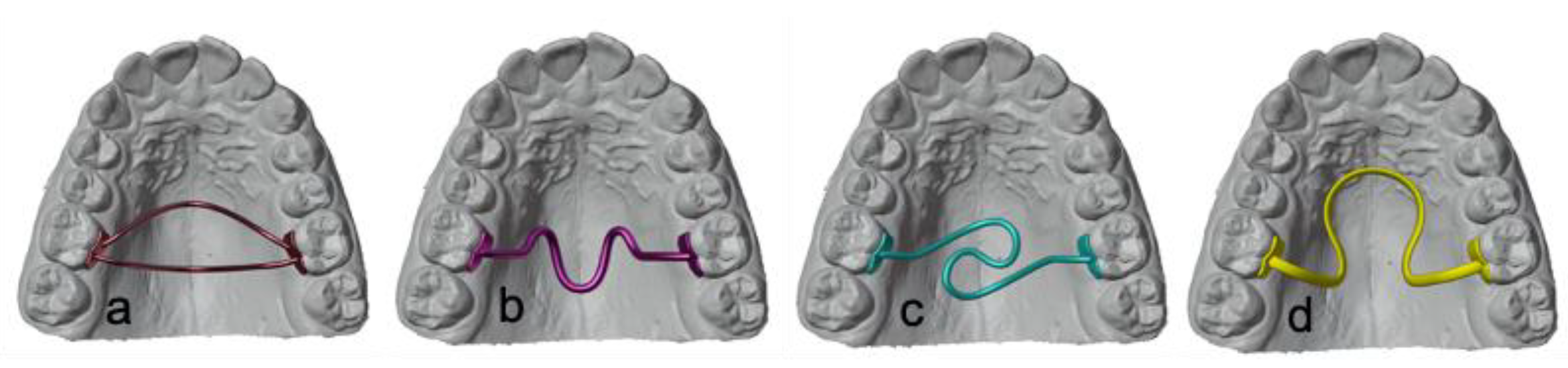
2.1. Computer-Aided Design (CAD)

A set of digital TPAs with various geometries were designed using the software Blender (version. 2.81) [27]. A randomly selected plaster model was taken from the archive of Department of Orthodontics, University Clinics of Dusseldorf. The plaster model was scanned to gain a digital model. On the first molars, partial shells covering the palatal aspect of the teeth were designed. These shells served to connect the TPAs with the molars. The arches of the TPAs had a horizontal width of 34 mm (from molar to molar), a height of about 14 mm and a distance to the palatal surface of 2 mm on average (Figure 1).
Out of a number of possible designs, four TPAs were selected that fulfilled common clinical requirements such as patient comfort and mechanical design criteria:
The Double-arch TPA consisted of two arches, each having a diameter of 1 mm (Figure 2a). The Triple-loop-arch TPA and the S-bow TPA were constructed with one connecting element and a diameter of 1.2 mm and 1.5 mm (Figure 2b,c) and the Omega-loop TPA showed an oval profile of 1 × 2 mm (Figure 2d). All dimensions are listed in Table 1.

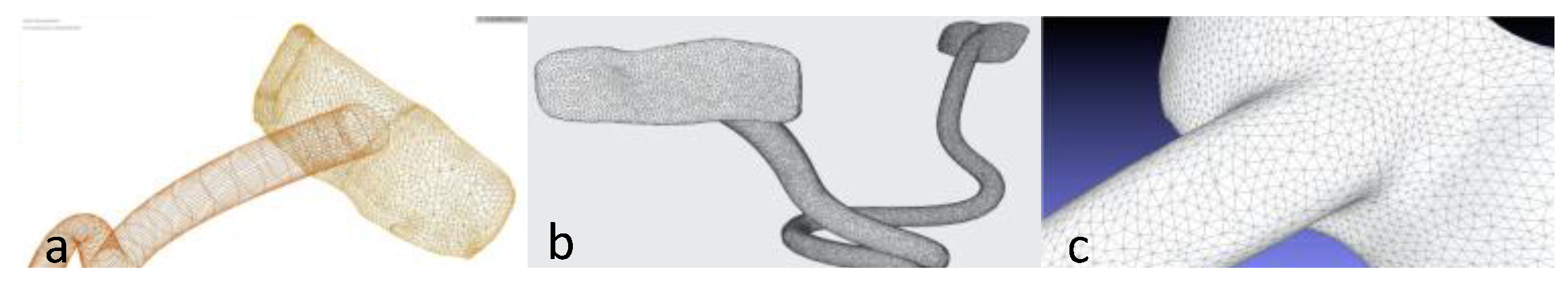
2.2. Creating of High-Quality Meshes

For the FEA, the meshes of the digital TPAs (Figure 3a), were triangulated and converted into meshes with high element quality using the Meshmixer program (version 3.4.35, 2017, Autodesk Meshmixer RRID:SCR_015736) (Figure 3b) and the MeshLab software (version 2016.12, https://www.meshlab.net, last accessed on 1 November 2021) for mesh corrections and optimizations (Figure 3c).

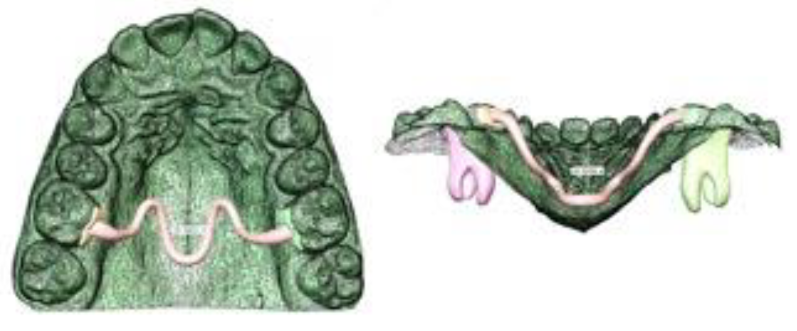
2.3. Finite Element Analysis (FEA)

The FEA was performed using the software FEBio (developed by SA Maas, BJ Ellis, GA Ateshian, JA Weiss) [28]. The pre-processor (FEBio-PreView, version 2.13) was used to build the finite element model and to define the boundary conditions. In order to guarantee an acceptable mesh quality, we bounded—for every tetrahedron—the ratio of the diameter of the circumsphere R and the length of the shortest edge L by the ratio R/L < 1.4. The number of the elements for each appliance are listed in Table 1.
The FE solver (FEBio-Run) was used to perform the calculations, and the post-processor (FEBio-PostView, version 2.4.4) was employed for visualization.
For the present study, the material parameters of the PEEK material were set to a Young’s modulus of 5.1 GPa and a Poisson’s ratio of 0.42, according to the parameters provided by the manufacturer of the material used for fabrication [29].
As boundary conditions, an activation in the horizontal plane between the two molar shells from 1 mm up to an expansion of 8 mm (4 mm per site) was defined, and computed in steps of 1 mm displacement each. The forces and moments acting at the point of force application (PF) on the inner surfaces of the shells (at the first upper molars), were determined. In addition, resulting moments at the centers of resistance (CR) were assessed. Moments around the vertical axis were considered to be rotatory, around the oro-vestibular axis to be angulatory and around the mesio-distal axis to account for tipping movements.

2.4. Computer-Aided Manufacturing (CAM)

The manufacturing of the four different PEEK TPAs were carried out by the dental laboratory “Dentes” (Dentes Fräszentrum GmbH, Neuss, Germany). The files were prepared for milling with the dental CAM system ZYKLONcam (KON-AN- TEC, Münster, Germany) and milled out of a PEEK disc from Merz Dental (PEEK BioSolution white, Merz Dental GmbH, Lütjeburg, Germany) with a 5-axis milling machine CORiTEC 350i Loader (Imes-icore GmbH, Eiterfeld, Germany). The support structures, which were necessary for fixation of the TPAs while milling, were carefully removed. No further finishing was required.

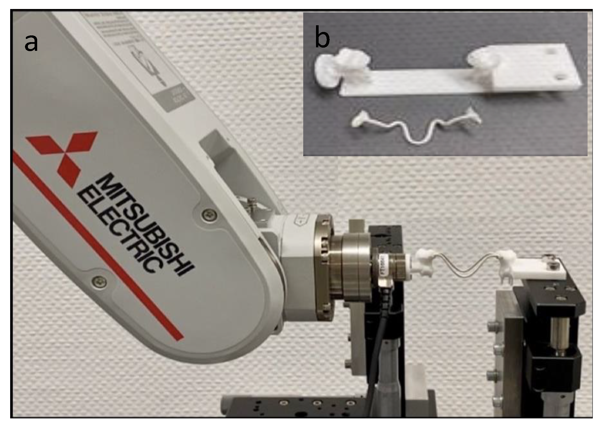
2.5. Set-Up of the Mechanical Testing

The mechanical in vitro test was performed by measurement system RMSBiomech, which consisted of a robotic arm, a force-moment sensor and an adjustable table (Figure 4a). Each of the TPAs was glued (Pattex, epoxy resin 2-component adhesive, Henkel, Germany) to custom designed and 3D printed fixation device (Figure 4b) made of a polyamide, printed by PROTIQ (Blomberg, Germany) and representing the original molars. The fixation devices were screwed to the sensor to allow measurement of the 3D forces and moments. The setup was constructed such that only the upper right first molar was movable, whereas the contralateral molar stayed attached to the table.
The measurement of the forces and the moments was carried out by a 6-axis force-moment sensor (FT Nano17, Schunk, Lauffen/Neckar, Germany), which was connected to the robotic arm via a magnetic attachment. The computer controlled robotic arm (Mitsubishi Electric, MELFA, RV-2FR, Ratingen, Germany) was capable of movements using all six spatial degrees of freedom.

2.6. Mechanical Testing

The software RMSBiomech controlling the robot stored the activation distance as well as the measured force Fx, Fy, Fz and moment components Mx, My, Mz. Each TPA was activated identical to the previous FEA in compression mode (8 mm in total, 4 mm per side) perpendicular to the mid-sagittal plane. Forces and moments were recorded in 0.1 mm steps from 1 to 8 mm of activation. This procedure was repeated ten times to calculate the mean values. The measured forces and moments represented those acting at the inner surfaces of the shells (PF) or the molars, respectively. The moments acting on the center of resistance (CR) were computed, assuming the CR to be positioned at 7 mm apically to the point of force application (PF), i.e., approximately 1–2 mm below the tri-furcation of the upper right molar [30,31].

3. Results

The results of the Finite Element Analysis and the mechanical testing were measured in all three dimensions and are reported in Table 2.

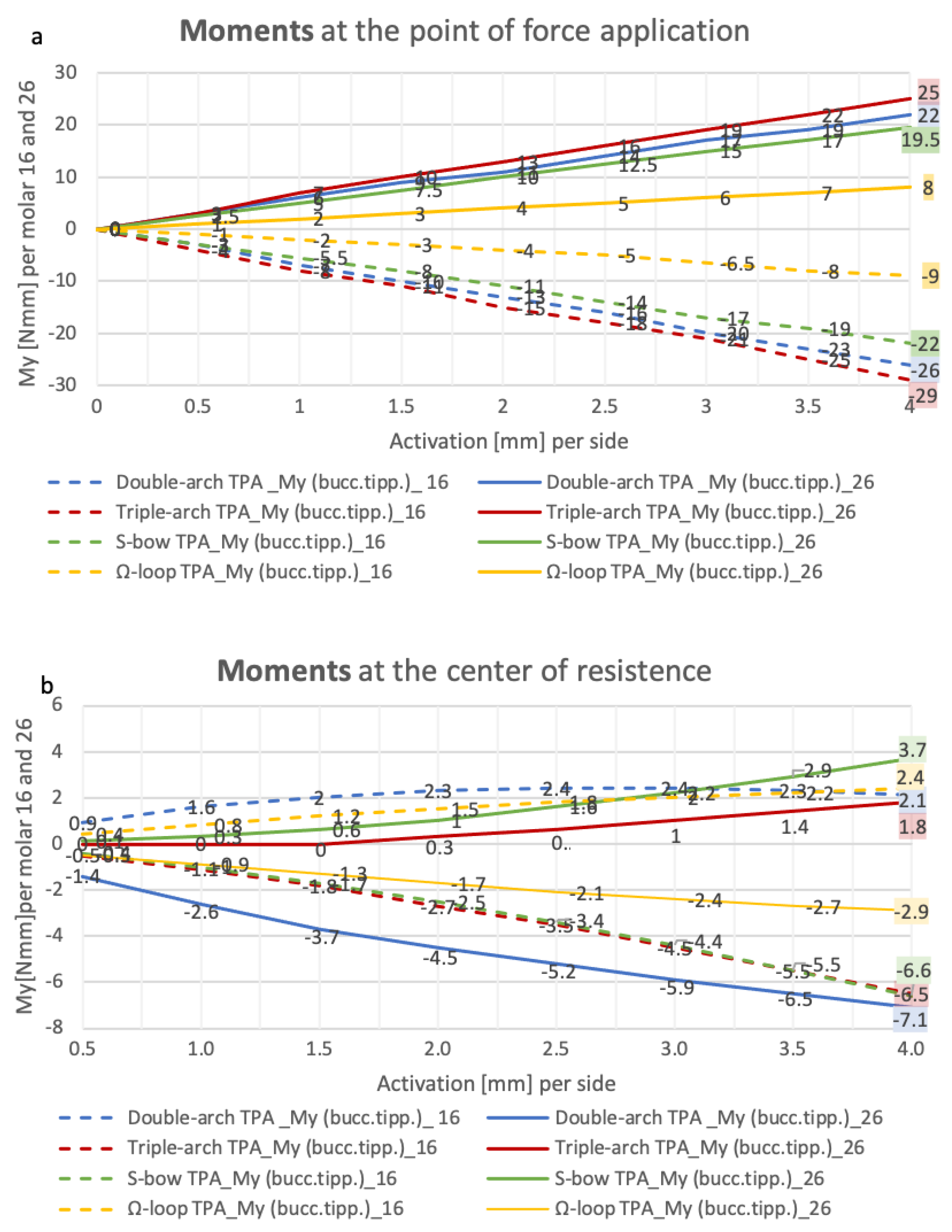
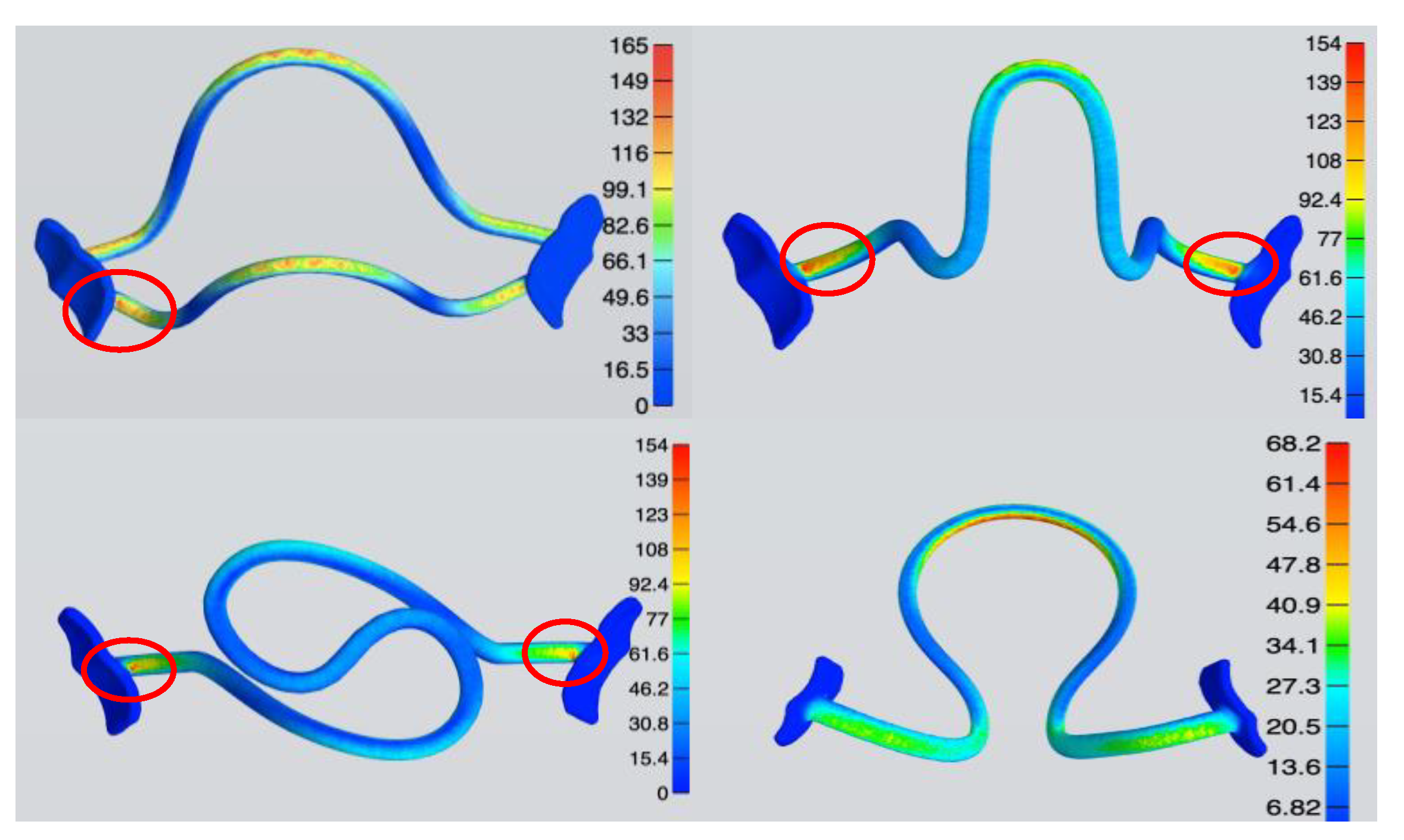
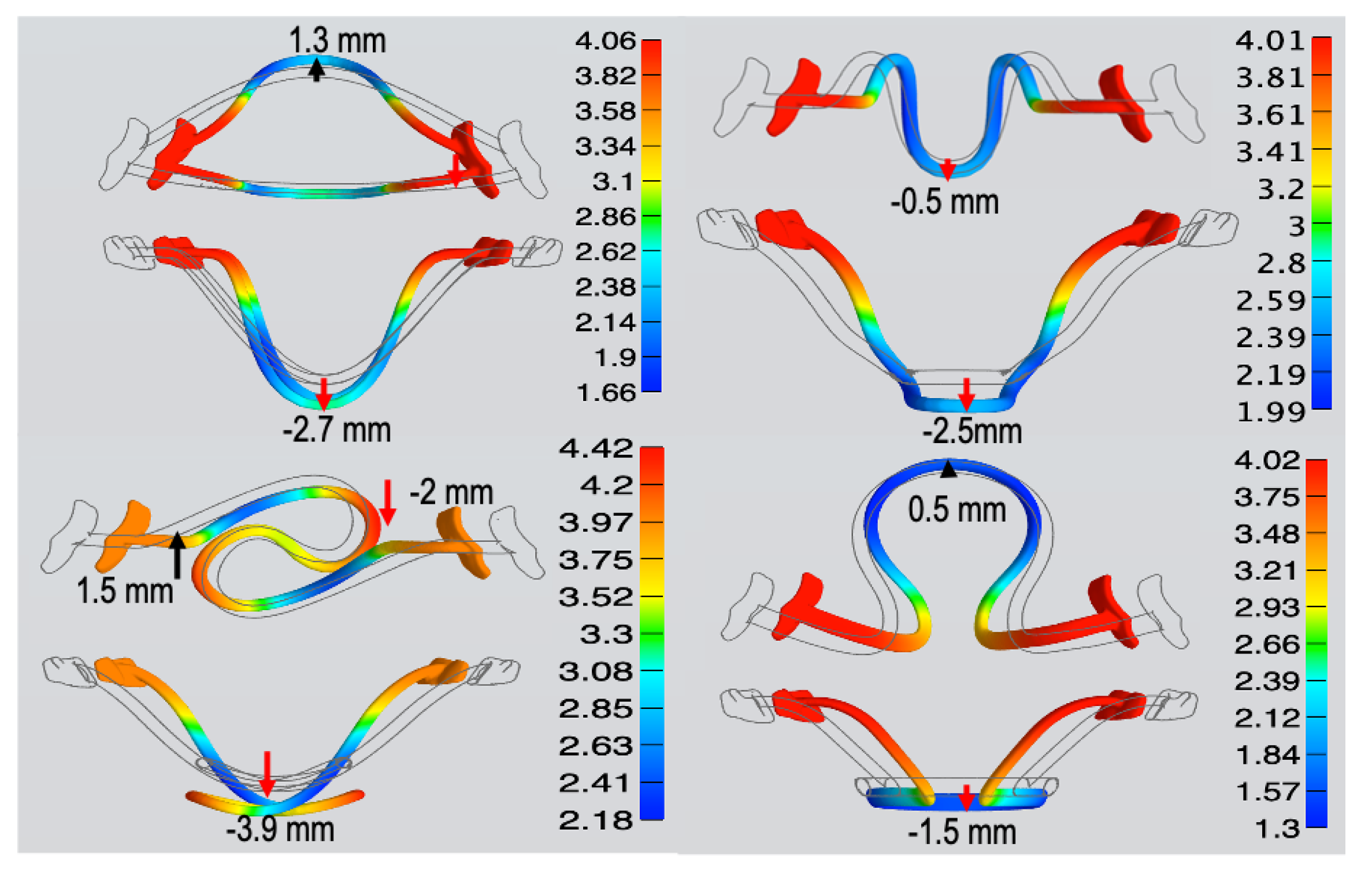
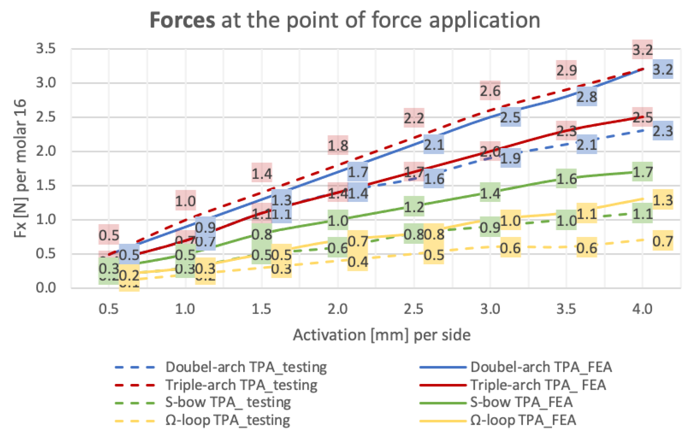
3.1. Finite Element Analysis

At a maximum activation of 4 mm per side in the transversal axis, the Double-arch TPA with two arches of 1 mm diameter each, generated the highest forces (3.1 Newton (N) per side). The Triple-loop-arch TPA and the S-bow TPA, both with a round diameter of 1.2 mm and 1.5 mm, generated 2.5 and 1.7 N per side. The Omega-loop TPA with an oval diameter of 1 × 2 mm and a big loop generated 1.3 N per side, the lowest force. In the sagittal and vertical direction, negligible forces less than 0.01 N were found.
The applied and resulting moments were assessed at CR and PF at the inner surface of the shell, palatal to the dental crown of the upper right molar. Overall, the highest moments were found around the mesio-distal axis representing a buccal tipping.
At the maximum activation of 4 mm per side, at CR, moments ranged from 2.1 Nmm (Double-arch TPA) to −6.6 Nmm (S-bow TPA), and, at PF, the moments ranged from −9 Nmm (Omega-loop TPA) to −29 Nmm (Triple-loop-arch TPA). The rotatory moments around the vertical axis reached a maximum of 6 Nmm (Triple-loop-arch TPA) at CR and −5.4 Nmm (Omega-loop TPA) at PF. The angulation, i.e., moments around the oro-vestibular axis, were very small for all treatment appliance with absolute values less than 0.5 Nmm. Figure 5a, b summarizes the buccal tipping at PF and CR for the investigated TPAs.
The FEA enabled calculation of the von Mises stresses for each TPA variant. Up to an activation of 3 mm per side, the local von Mises stresses ranged from 51 to 128 MPa and sometimes slightly exceeded the yield point from PEEK of 120 MPa. Upon further activation of the TPAs up to 4 mm, three appliances produced local von Mises stress clearly above the yield point (S-bow TPA and Triple-loop-arch TPA: 154 MPa and Double-arch TPA: 165 MPa). The von Mises stresses for the different TPA variants are visualized in Figure 6 for a bilateral activation of 4 mm. It can be seen that the highest material stresses occurred at the interface between the TPA and the shells (marked in red-orange).
The displacement in the sagittal direction differed depending on the TPA geometry: Anterior movement was seen for the Double-arch TPA and the Omega-loop TPA (1.3 mm and 0.5 mm), whereas distal displacement was seen for the Triple-loop-arch TPA (−0.5 mm). A different pattern was seen for the S-bow TPA where one side moved to the anterior, and the other in a distal direction (1.5 mm and −2 mm). In the apical direction, movements ranged from −1.5 mm (Omega-loop TPA) to −3.9 mm (S-bow TPA).
Figure 7 summarizes the deformation pattern of the four TPAs in all three dimensions. It can be seen that apical displacement was most pronounced for the S-bow TPA and the Double-arch TPA, reaching 3.9 mm and 2.7 mm, respectively.

3.2. Mechanical Testing

The resulting forces and moments of the mechanical testing were measured in all three dimensions and are shown in Table 2. In contrast to the FEA, the Triple-loop-arch TPA showed the highest forces (3.2 N per side) and the Double-arch TPA the second highest forces (2,3 N per side) at an activation of 4 mm per side. Likewise, to the FEA, the S-bow TPA and the Omega-loop TPA generated lower forces per side (1.1 N per side and 0.7 N). Figure 8 compares the resulting forces from the FEA with the mechanical tests of the investigated TPAs. In the sagittal and apical direction, negligible forces smaller than 0.2 N were identified.
For the mechanical testing, resulting moments were assessed only at the CR. Similar to the FEA, the highest moments occurred around the mesio-distal axis representing a buccal tipping ranging from 1.1 Nmm (Double-arch TPA) to −6 Nmm (Triple-loop-arch TPA). The rotatory moments around the vertical axis ranged from 1.3 Nmm (Double-arch TPA) to −4.7 Nmm (Triple-loop-arch TPA). The angulation, around the oro-vestibular axis, was lowest and ranged from 0.1 to −0.3 Nmm for all appliances.

4. Discussion

Digital workflows and computer-aided design (CAD) are transforming the daily work in all dental disciplines. In orthodontics, they enable the provision of individualized appliances designed specifically to the patient’s needs.
Owing to the advancement of computer-aided manufacturing (CAM), new materials for 3D printing or 5-axis milling are becoming available [32]. Most of the printable polymers currently available on the dental market are limited to temporary use in the mouth. In orthodontics, they are utilized for insertion guides of orthodontic mini-implants [33,34] or surgical splints for orthognathic surgery [35]. Fully digitally planned and CAM-fabricated appliances made of printed or milled materials have been described in the literature. They are utilized for active treatment and retention purposes [11,12,13,36,37,38].
The biocompatible high-performance polymer polyether ether ketone (PEEK) that was analyzed in the present study has been used in dentistry for dental implants [18,19,20] as well as for permanent and removable dentures [14,15]. In the orthodontic field, PEEK has been tested for the manufacturing of removable and fixed space maintainers. Owing to the low modulus of elasticity, it has also been tested for orthodontic wires made of or covered by PEEK [23,24,25]. Therefore, the present study investigated whether PEEK could also be suitable for the CAM fabrication of transpalatal arches.
In contrast to the traditional transpalatal arch made of stainless steel or TMA wire, the use of digital design programs enables the user to create customized and precise treatment appliances for specific needs. The TPA geometries presented in this article reflect the wide range of design possibilities.
PEEK, in contrast to stainless steel (160 GPa) or TMA (80 GPa), has a significantly lower Young’s modulus of only 3 to 5 GPa. When employed as a material for orthodontic purposes, forces and moments of much smaller magnitudes can be expected. Accordingly, the activation range of the TPAs made out of PEEK that were measured in the present study was considerably higher compared to values previously reported for TPAs made of stainless steel (maximum activation < 3 mm) or TMA (maximum activation < 5–6 mm).
Up to an activation of 6 mm, none of the TPA geometries presented in this study exceeded the recommended force limit of 2.5 N [5]. The S-bow TPA and the Omega-loop TPA generated expansion forces below 1.5 N up to an activation of 8 mm, implicating that a further activation would be conceivable for the respective geometries.
Out of the TPAs tested in this study, the Double-arch TPA and the Triple-loop-arch TPA generated the highest forces, which were in the range of 2.5 to 3.0 N and appeared appropriate for orthodontic purposes. Among the two, the Double-arch TPA showed rather low moments and could thus be well suited for expansion or—possibly with an enlarged or modified cross section—also as an anchorage unit. The Triple-loop-arch TPA generated similar forces but higher moments (rotation −6.6 Nmm) and may therefore also be suited for molar derotation. The S-bow TPA generated lower forces and higher moments (rotation 3 to 6 Nmm), which may in principle be eligible for orthodontic treatment. However, the FEA revealed that the two “S” arches might end up in direct contact upon higher activation, which has to be considered in the case of clinical application. The Omega-loop-arch TPA, with its large spring, generated very low forces (about 1.0 N) and may therefore not be useful for expansion or for anchorage.
The traditional TPA made of stainless steel or TMA is usually connected to the molars via palatal attachments. This plug-in connection has the advantage that the palatal arch can be easily removed and re-inserted for activation. However, a limitation of this approach is related to the slot play leading to undesirable side effects, such as the unwanted reduction in torque moments [5,7] Another limitation of conventional TPAs is related to the fact that their frequent re-activation is required.
The CAD/CAM-fabricated TPAs consist of one piece and should be directly bonded to the palatal surface of the molars. Due to the high dimensional stability of the palatal connection from the arch to the tooth, side effects can be reduced and three-dimensional tooth movements can be achieved in a more precise manner. Due to the large activation range, regularly re-activating of the TPAs might not be necessary.
Comparable to the activation of TPAs made of stainless steel [8], three out of four TPAs made of PEEK exceeded the yield point at a bilateral activation of 4 mm in the FEA, whereas this did not occur for a bilateral activation of 3 mm. Accordingly, we can expect that higher activations may lead to an irreversible deformation during insertion. In this case, the TPAs made out of PEEK might not recover completely. Consequently, the intended tooth movement might not be carried out to the full extent. In the mechanical in vitro analysis, however, none of the PEEK TPAs investigated in this study showed any visible deformation. Hence, for the geometries investigated, the maximum activation ranges of the PEEK TPAs are most likely to be in a range slightly below 4 mm per side.
On average, the values measured in the mechanical in vitro testing for the force systems were lower than the values calculated in the FEA. Only one appliance (Triple-loop-arch TPA) showed higher values in the test than in the FEA. Possibly, this could be related to the fact that a linear elasticity of the PEEK material was assumed for the FEA. However, the PEEK material—as with most polymers—shows a non-linear behavior above a certain load. Therefore, a change in the material structure of the PEEK polymer during activation (horizontal compression) and an incomplete recovery of the material in the mechanical testing may occur. It may be speculated that this could be the reason for the lower forces in the in vitro testing, and future studies are required to further investigate this aspect.
The FEA revealed that the highest material stresses occurred at the junction of the connecting elements to the shells. Using CAD-supported planning at this point, the user has the possibility to strengthen the TPAs in the areas with the highest material stress. This might lead to a reduction in the material stress when subjected to similar force systems.
Finally, with the help of the FEA, it was possible to obtain information on the deformation of each treatment appliance in all three dimensions. It was observed that greater transversal activation leads to significant apical movement of the treatment appliance from 1.5 up to almost 4 mm, depending on the TPA geometry. A palatal distance of about 2 mm, as described in this study, of the TPAs would result in contact with the palatal mucosa during insertion. This fact should be kept in mind in the virtual planning of the TPAs designed by CAD.

5. Conclusions

The present study showed that CAD–CAM-manufactured transpalatal arches (TPA) made of PEEK might be a promising alternative to conventional materials.
The FEA was found to be suitable to investigate the mechanical behavior of different CAD/CAM-fabricated TPA geometries. The mechanical in vitro analysis supplemented the FEA by enabling measurement of the forces and moments acting on both molars simultaneously. In combination with the FEA, predictions about the force systems acting on the molars by CAD/CAM-fabricated PEEK TPAs could be obtained in all three dimensions.
The TPA geometries presented in this study showed clinically appropriate expansion forces up to 3 N per side. Due to the low load-deflection rate of the flexible PEEK material, the activation ranges are much higher in comparison to conventional TPAs. The four different geometries utilized in the study reflect the wide variability in design options. The Triple-loop-arch TPA with a force system ranging from 2.5 to about 3 N appeared to be most appropriate for the application of moments, whereas the Double-arch TPA, which delivered force systems of comparable magnitude, seemed to be most appropriate for the expansion as well as anchorage of the molars. In the future, the development of customized TPAs for specific patients’ needs might become possible using CAD.
The practical benefits of CAD/CAM-fabricated appliances are currently advancing owing to the development of novel 3D-printable materials and improvements in CAD software. However, their introduction to clinical settings requires validation of their eligibility by means of simulated and biomechanical testing, and analysis of biocompatibility. Whereas PEEK has already demonstrated its suitability for permanent use in the mouth, only a few studies have assessed its applicability as a retention device in orthodontics. This study presented that PEEK may also be effective as a CAD–CAM-fabricated active orthodontic appliance and might offer a metal-free, aesthetic alternative to conventional approaches. As the 5-axis milling out of a PEEK disc is associated with a high material loss, improvements in additive 3D printing technology will most likely reduce costs in the future.
The behavior of PEEK under in vivo (intraoral) conditions should be evaluated in future experimental studies.

Author Contributions

C.M.: Conceptualization, methodology, formal analysis, investigation, writing—original draft preparation. D.D.: Conceptualization, methodology, formal analysis, investigation, writing—review and editing. J.G.S.: methodology, software, visualization, formal analysis. J.H.W.: Conceptualization, methodology, project administration. K.B.: Conceptualization, writing—original draft preparation, writing—review and editing. All authors have read and agreed to the published version of the manuscript.

Funding

This research received no external funding.

Institutional Review Board Statement

The present study was approved by the ethical committee of the University of Dusseldorf (Ref. no. 2019-643, date of approval: 4 September 2019).

Informed Consent Statement

Not applicable.

Data Availability Statement

Data will be provided upon reasonable request.

Acknowledgments

The authors thank the dental laboratory “Dentes” (Fräszentrum GmbH, Neuss, Germany) for their kind support in the manufacturing of the different TPAs.

Conflicts of Interest

The authors declare no conflict of interest.

References

  1. Baldini, G.; Luder, H.U. Influence of Arch Shape on the Transverse Effects of Transpalatal Arches of the Goshgarian Type during Application of Buccal Root Torque. Am. J. Orthod. 1982, 81, 202–208. [Google Scholar] [CrossRef]
  2. Burstone, C.J.; Koenig, H.A. Precision Adjustment of the Transpalatal Lingual Arch: Computer Arch Form Predetermination. Am. J. Orthod. 1981, 79, 115–133. [Google Scholar] [CrossRef]
  3. Burstone, C.J.; Manhartsberger, C. Precision Lingual Arches. Passive Applications. Am. J. Orthod. 1981, 80, 1–16. [Google Scholar] [CrossRef]
  4. Burstone, C.J. Precision Lingual Arches. Active Applications. J. Clin. Orthod. JCO 1989, 23, 101–109. [Google Scholar]
  5. Hoederath, H.; Bourauel, C.; Drescher, D. Differences between Two Transpalatal Arch Systems upon First-, Second-, and Third-Order Bending Activation. J. Orofac. Orthop. Fortschr. Kieferorthopädie 2001, 62, 58–73. [Google Scholar] [CrossRef]
  6. Tsetsilas, M.; Konermann, A.-C.; Keilig, L.; Reimann, S.; Jäger, A.; Bourauel, C. Symmetric and Asymmetric Expansion of Molars Using a Burstone-Type Transpalatal Arch. J. Orofac. Orthop. Fortschritte Kieferorthopädie 2015, 76, 377–390. [Google Scholar] [CrossRef]
  7. Wichelhaus, A.; Sander, C.; Sander, F.G. Development and Biomechanical Investigation of a New Compound Palatal Arch. J. Orofac. Orthop. Kieferorthopädie 2004, 65, 104–122. [Google Scholar] [CrossRef]
  8. Gündüz, E.; Crismani, A.G.; Bantleon, H.P.; Hönigl, K.D.; Zachrisson, B.U. An Improved Transpalatal Bar Design. Part II. Clinical Upper Molar Derotation—Case Report. Angle Orthod. 2003, 73, 244–248. [Google Scholar] [CrossRef]
  9. Ambrositsch, P.; Bantleon, H.-P. Der S-Garian TPA—Einsatzmöglichkeiten und Vorteile des Transpalatinalbogendesigns. Informationen Aus Orthod. Kieferorthopädie 2016, 48, 7–10. [Google Scholar] [CrossRef]
  10. Nikkerdar, A. Butterfly Arch: A Device for Precise Controlling of the Upper Molars in Three Planes of Space. J. Dent. Tehran Iran. 2013, 10, 221–226. [Google Scholar]
  11. Graf, S.; Vasudavan, S.; Wilmes, B. CAD/CAM Metallic Printing of a Skeletally Anchored Upper Molar Distalizer. J. Clin. Orthod. JCO 2020, 54, 140–150. [Google Scholar]
  12. Graf, S.; Cornelis, M.A.; Hauber Gameiro, G.; Cattaneo, P.M. Computer-Aided Design and Manufacture of Hyrax Devices: Can We Really Go Digital? Am. J. Orthod. Dentofac. Orthop. 2017, 152, 870–874. [Google Scholar] [CrossRef] [Green Version]
  13. Graf, S.; Vasudavan, S.; Wilmes, B. CAD-CAM Design and 3-Dimensional Printing of Mini-Implant Retained Orthodontic Appliances. Am. J. Orthod. Dentofac. Orthop. 2018, 154, 877–882. [Google Scholar] [CrossRef] [Green Version]
  14. Skirbutis, G. PEEK Polymer’s Properties and Its Use in Prosthodontics. A Review. Stomatol. Balt. Dent. Maxillofac. J. 2018, 20, 54–58. [Google Scholar]
  15. Alexakou, E. PEEK High Performance Polymers: A Review of Properties and Clinical Applications in Prosthodontics and Restorative Dentistry. Eur. J. Prosthodont. Restor. Dent. 2019, 27, 113–121. [Google Scholar] [CrossRef]
  16. Jockusch, J.; Özcan, M. Additive Manufacturing of Dental Polymers: An Overview on Processes, Materials and Applications. Dent. Mater. J. 2020, 39, 345–354. [Google Scholar] [CrossRef] [Green Version]
  17. Wang, Y.; Müller, W.-D.; Rumjahn, A.; Schwitalla, A. Parameters Influencing the Outcome of Additive Manufacturing of Tiny Medical Devices Based on PEEK. Mater. Basel Switz. 2020, 13, 466. [Google Scholar] [CrossRef] [Green Version]
  18. Schwitalla, A.; Müller, W.-D. PEEK Dental Implants: A Review of the Literature. J. Oral Implantol. 2013, 39, 743–749. [Google Scholar] [CrossRef]
  19. Whitty, T. PEEK—A New Material for CAD/CAM Dentistry. eLABORATE 2014, 32–36. Available online: https://panadent.co.uk/wp-content/uploads/2014/11/PEEK-A-new-material-for-CADCAM-dentistry.pdf (accessed on 21 November 2021).
  20. Mendes, J.M.; Botelho, P.C.; Mendes, J.; Barreiros, P.; Aroso, C.; Silva, A.S. Comparison of Fracture Strengths of Three Provisional Prosthodontic CAD/CAM Materials: Laboratory Fatigue Tests. Appl. Sci. 2021, 11, 9589. [Google Scholar] [CrossRef]
  21. Ierardo, G.; Luzzi, V.; Lesti, M.; Vozza, I.; Brugnoletti, O.; Polimeni, A.; Bossu, M. Peek Polymer in Orthodontics: A Pilot Study on Children. J. Clin. Exp. Dent. 2017, 9, e1271–e1275. [Google Scholar] [CrossRef]
  22. Xepapadeas, A.B.; Weise, C.; Frank, K.; Spintzyk, S.; Poets, C.F.; Wiechers, C.; Arand, J.; Koos, B. Technical Note on Introducing a Digital Workflow for Newborns with Craniofacial Anomalies Based on Intraoral Scans—Part I: 3D Printed and Milled Palatal Stimulation Plate for Trisomy 21. BMC Oral Health 2020, 20, 20. [Google Scholar] [CrossRef] [PubMed]
  23. Shirakawa, N.; Iwata, T.; Miyake, S.; Otuka, T.; Koizumi, S.; Kawata, T. Mechanical Properties of Orthodontic Wires Covered with a Polyether Ether Ketone Tube. Angle Orthod. 2018, 88, 442–449. [Google Scholar] [CrossRef] [PubMed]
  24. Tada, Y.; Hayakawa, T.; Nakamura, Y. Load-Deflection and Friction Properties of PEEK Wires as Alternative Orthodontic Wires. Materials 2017, 10, 914. [Google Scholar] [CrossRef] [PubMed]
  25. Maekawa, M.; Kanno, Z.; Wada, T.; Hongo, T.; Doi, H.; Hanawa, T.; Ono, T.; Uo, M. Mechanical Properties of Orthodontic Wires Made of Super Engineering Plastic. Dent. Mater. J. 2015, 34, 114–119. [Google Scholar] [CrossRef] [Green Version]
  26. Krey, K.-F. 3D-Printed Orthodontic Brackets—Proof of Concept Dreidimensional Gedruckte Kieferorthopädische Brackets—Eine Machbarkeitsstudie. Int. J. Comput. Dent. 2016, 19, 351–362. [Google Scholar] [PubMed]
  27. Community, B.O. Blender—A 3D Modelling and Rendering Package; Stichting Blender Foundation: Amsterdam, The Netherlands, 2018; Available online: http://www.blender.org (accessed on 30 July 2020).
  28. Maas, S.A.; Ellis, B.J.; Ateshian, G.A.; Weiss, J.A. FEBio: Finite elements for biomechanics. J. Biomech. Eng. 2012, 134, 011005. [Google Scholar] [CrossRef]
  29. Available online: https://www.merz-dental.de/fileadmin/user_upload/downloads/IFU/GBA_PEEK_BioSolution_907187-2021-08-05_907260-2021-10-02_907328-2021-09-01.pdf (accessed on 10 September 2019).
  30. Schwindling, F.-P. Vom Centroid zur Widerstandszone. Kieferorthopädie 2020, 34, 39–46. [Google Scholar]
  31. Viecilli, R.F.; Budiman, A.; Burstone, C.J. Axes of Resistance for Tooth Movement: Does the Center of Resistance Exist in 3-Dimensional Space? Am. J. Orthod. Dentofac. Orthop. 2013, 143, 163–172. [Google Scholar] [CrossRef]
  32. Scribante, A.; Gallo, S.; Pascadopoli, M.; Canzi, P.; Marconi, S.; Montasser, M.A.; Bressani, D.; Gandini, P.; Sfondrini, M.F. Properties of CAD/CAM 3D Printing Dental Materials and Their Clinical Applications in Orthodontics: Where Are We Now? Appl. Sci. 2022, 12, 551. [Google Scholar] [CrossRef]
  33. Wilmes, B.; Vasudavan, S.; Drescher, D. CAD-CAM–Fabricated Mini-Implant Insertion Guides for the Delivery of a Distalization Appliance in a Single Appointment. Am. J. Orthod. Dentofac. Orthop. 2019, 156, 148–156. [Google Scholar] [CrossRef] [PubMed] [Green Version]
  34. Gabriele, O.D.; Dallatana, G.; Riva, R.; Vasudavan, S.; Wilmes, B. The Easy Driver for Placement of Palatal Mini-Implants and a Maxillary Expander in a Single Appointment. J. Clin. Orthod. 2017, 51, 728–737. [Google Scholar] [PubMed]
  35. Brauer, L.; Pausch, N. Digital unterstützte kombiniert kieferorthopädisch-kieferchirurgische Therapie. Zahnmed. Up2date 2018, 12, 215–234. [Google Scholar] [CrossRef]
  36. Al Mortadi, N.; Eggbeer, D.; Lewis, J.; Williams, R.J. CAD/CAM/AM Applications in the Manufacture of Dental Appliances. Am. J. Orthod. Dentofacial Orthop. 2012, 142, 727–733. [Google Scholar] [CrossRef]
  37. Wolf, M.; Schumacher, P.; Jäger, F.; Wego, J.; Fritz, U.; Korbmacher-Steiner, H.; Jäger, A.; Schauseil, M. Novel Lingual Retainer Created Using CAD/CAM Technology: Evaluation of Its Positioning Accuracy. J. Orofac. Orthop. Fortschr. Kieferorthopadie Organ Off. J. Dtsch. Ges. Kieferorthopadie 2015, 76, 164–174. [Google Scholar] [CrossRef]
  38. Kravitz, N.D.; Grauer, D.; Schumacher, P.; Jo, Y. Memotain: A CAD/CAM Nickel-Titanium Lingual Retainer. Am. J. Orthod. Dentofacial Orthop. 2017, 151, 812–815. [Google Scholar] [CrossRef] [Green Version]
Figure 1. Computer-Aided Design (CAD) of one TPA Geometry.
Applsci 12 01590 g001
Figure 2. Four different designs of digital TPA Geometries (a) Double-arch TPA, (b) Triple-loop-arch TPA, (c) S-bow TPA, (d) Omega-loop TPA.
Applsci 12 01590 g002
Figure 3. Mesh creation and optimization (a) Blender, (b) Meshmixer, (c) MeshLab.
Applsci 12 01590 g003
Figure 4. Experimental setup of the mechanical in vitro testing; (a) Robotic arm with supersensitive force–moment sensor and position table; (b) 3D printed polyamide fixation device with one TPA, milled out of PEEK.
Applsci 12 01590 g004
Figure 5. (a,b) FEA, resulting moments in Newton millimeter (Nmm) for buccal tipping per molar 16 (dashed line) and 26 (continuous line) measured by transversal activation of 0.5 to 4 mm per side; (a) at the point of force application; (b) at the center of resistance.
Applsci 12 01590 g005
Figure 6. FEA, graphical illustration of the von Mises stress at a maximum of 4 mm bilateral activation per side. The side scale indicates the corresponding numerical data (here: megapascals) to the color gradient, blue shows the lowest stress and red the highest stress (areas marked in red-orange).
Applsci 12 01590 g006
Figure 7. FEA, graphical visualization of the deformation pattern at a maximum of 4 mm bilateral activation per side. The side scale indicates the corresponding numerical values (here: millimeters) to the color gradient, blue indicates the smallest movement and red the largest.
Applsci 12 01590 g007
Figure 8. Mechanical test (dashed line) vs. FEA (continuous line): resulting forces in Newton (N) in oro-vestibular direction per molar by transversal activation of 0.5 to 4 mm per side.
Applsci 12 01590 g008
Table 1. Dimensions of the four different designs: horizontal (x-axis), sagittal (y-axis), vertical (z-axis), arch diameter and number of the elements in the FEA.
Dimensions (mm)Double-Arch TPA
Applsci 12 01590 i001
Triple-Loop-Arch TPA
Applsci 12 01590 i002
S-Bow TPA
Applsci 12 01590 i003
Omega-Loop TPA
Applsci 12 01590 i004
Horizontal34343434
Sagittal13111420
Vertical141414.510
Cross section1 each1.51.21 × 2
Number of elements in the FEA155,578136,341167,257151,933
Table 2. a–d Measurements of the finite element analysis and the mechanical testing; Forces: Fx (transversal), Fy (sagittal), Fz (vertical); Moments: Mx (angulation), My (buccal tipping), Mz (rotation); von Mises stresses; (a) Double-arch TPA, (b) Triple-loop-arch TPA, (c) S-bow TPA, (d) Omega-loop TPA.
Activation
(mm)
Finite Element AnalysisMechanical Testing
ForcesMoments at the Point of Force Application (PF)Moments at the Center of Resistance (CR)von Mises
Stress
[MPa]
ForcesMoments at the Center of Resistance (CR)
Fx (N)
FEA
Fy(N)
FEA
Fz (N)
FEA
Mx
Nmm
FEA.
My
Nmm
FEA
Mz
Nmm
FEA
Mx
Nmm
FEA
My
Nmm
FEA
Mz
Nmm
FEA
Fx (N)
test
Fy(N)
test
Fz (N)
test
Mx
Nmm
test
My
Nmm
test
Mz
Nmm
test
Applsci 12 01590 i005(a) Double-arch TPA
0.50.5000−3−0.500.90.3 0.400−0.10.50.1
10.900−0.1−7−1.301.60.5460.700.1−0.10.80.2
1.51.300−0.2−10−2020.7 1.100.1−0.11.10.4
21.700.1−0.2−13−2.502.30.8891.400.1−0.11.30.5
2.52.100.1−0.3−16−3−0.12.40.9 1.600.1−0.11.30.7
32.50.10.1−0.3−20−3.8−0.12.41.01281.900.2−0.11.30.9
3.52.80.10.1−0.4−23−4.5−0.12.31.0 2.100.2−0.11.21.1
43.20.10.1−0.5−26−5−0.12.11.01652.30.10.2−0.21.11.3
Applsci 12 01590 i006(b) Triple-loop-arch TPA
0.50.400−0.1−40.10−0.50.8 0.5000−0.5−0.7
10.700−0.1−80.2−0.1−1.11.7431.0000−1.1−1.3
1.51.100.1−0.2−110.3−0.1−1.82.4 1.400.10−1.7−1.9
21.400.1−0.2−150.5−0.2−2.73.2831.800.10.1−2.5−2.5
2.51.700.1−0.3−180.5−0.2−3.53.9 2.200.10.1−3.3−3.1
32.000.1−0.3−210.7−0.3−4.54.61202.600.10.2−4.2−3.7
3.52.300.1−0.4−250.9−0.4−5.55.3 2.900.10.2−5.1−4.2
42.500.1−0.4−291−0.4−6.56.01543.200.10.2−6.0−4.7
Applsci 12 01590 i007(c) S-bow TPA
0.50.300−0.1−30.20−0.40.7 0.2000.0−0.2−0.3
10.500−0.1−5.50.30−1.01.3420.3000.0−0.5−0.6
1.50.800−0.1−80.40−1.71.8 0.5000.0−0.8−0.8
21.000−0.2−110.50−2.52.3810.600−0.1−1.1−1.1
2.51.200−0.2−140.50.1−3.42.8 0.800−0.1−1.6−1.3
31.40.10.1−0.2−170.50.2−4.43.21190.900−0.2−2.1−1.4
3.51.60.10.1−0.3−190.50.2−5.53.5 1.000−0.3−2.6−1.5
41.70.10.1−0.3−220.50.3−6.63.71541.100−0.3−3.2−1.7
Applsci 12 01590 i008(d) Omega-loop TPA
0.50.2000−1−0.700.4−0.4 0.1000.00.10.3
10.3000−2−1.400.8−0.7170.2000.00.30.6
1.50.5000−3−201.2−1.1 0.3000.00.50.9
20.7000−4−2.701.5−1.5350.4000.00.61.1
2.50.8000−5−3.401.8−1.8 0.5000.10.81.4
31.000−0.1−7−402.0−2.2510.6000.10.91.7
3.51.100−0.1−8−4.70.12.2−2.6 0.6000.11.02.0
41.300−0.1−9−5.40.12.4−2.9680.7000.11.12.3
Publisher’s Note: MDPI stays neutral with regard to jurisdictional claims in published maps and institutional affiliations.

