1. Introduction
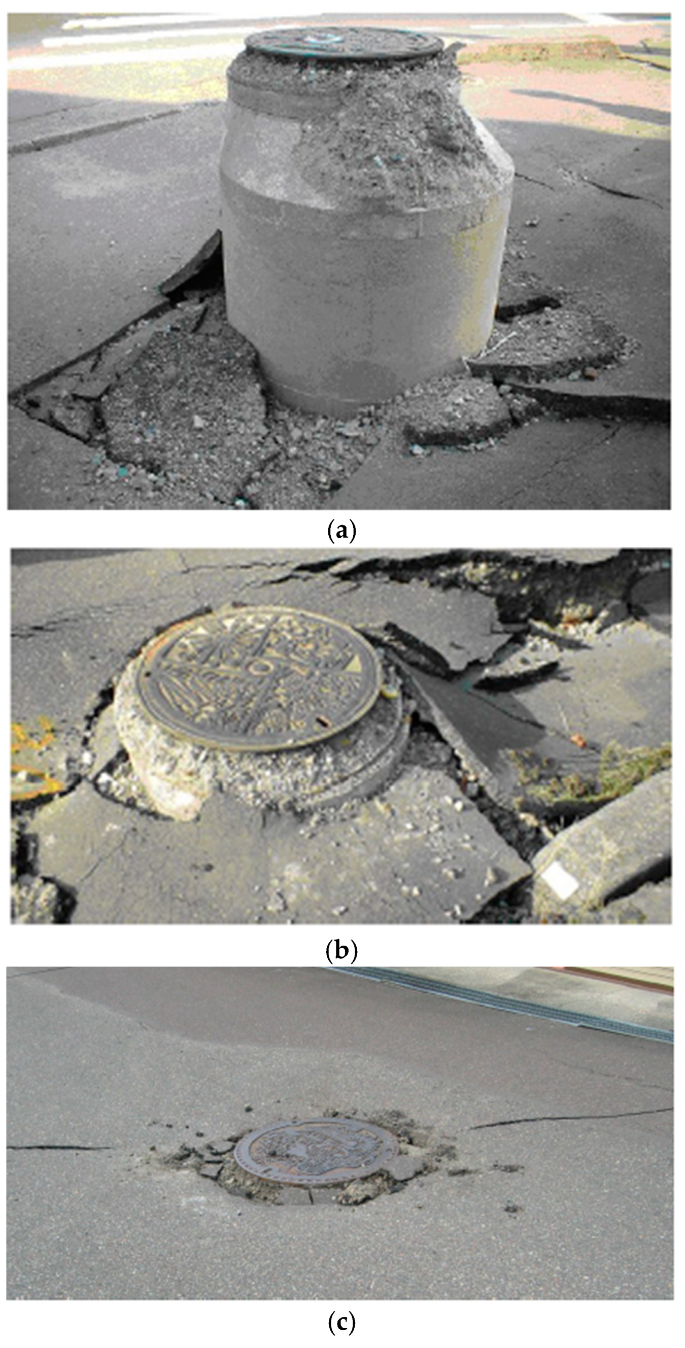
It has been confirmed that manholes may protrude from the road surface, as shown in
Figure 1, due to the liquefaction of the ground during a large earthquake. As a result, the sewerage pipeline that connects to the manhole underground can become damaged. The Great East Japan Earthquake of 2011 caused enormous damage to reclaimed coastal areas of Tokyo Bay and, according to the Ministry of Land, Infrastructure, Transport and Tourism, Japan, the total number of damaged manholes reached 6699 [
1,
2,
3].
When the uplifting of a manhole occurs, it may bring about not only dysfunction, such as the loss of the ability of sewage to flow, which is the original function of sewerage, but also displacements, such as that of the pipeline connecting the manhole, which makes drainage difficult [
4]. This also means that water cannot be used, which hinders people’s lives and affects environmental hygiene. Therefore, it is necessary to improve the stability of manholes during earthquakes, because their instability could also cause traffic dysfunctions, such as the obstruction of important emergency transportation routes immediately after a disaster, which would take time to restore.
As measures against the liquefaction of sewerage pipeline facilities currently in use, the compaction of backfill soil, backfilling with crushed stones, improvement of the solidification of the backfill soil, and methods of releasing pore water pressure into manholes have been devised. However, effective and economic measures against the uplifting of existing manholes are still in their developmental stages.
Therefore, this study proposes a weighting method that increases the self-weight of the manhole as a countermeasure against the uplifting of manholes during earthquakes. The applicability of this weighting method will be clarified by conducting case studies from the viewpoint of the safety factor for manhole uplifting and the quantity () of the manhole uplifting.
2. Overview of Manholes and Weighting Method
2.1. Manholes
A manhole is a vertical hole made to connect the surface of the ground with a sewer pipeline, or electric or communication cables buried underground [
4,
5]. It is mainly made for the purposes of the inspection, repair, and cleaning of underground facilities. Manholes usually have a cover to prevent anything or anyone from falling into them. Most manhole covers are made of steel. Many of them are circular in shape in order to prevent them from falling in [
6]. Manhole covers are made to be very heavy to prevent them from being easily opened or stolen. The surface of these covers has irregularities to prevent them from being slippery. In addition, a small hole is made in advance in each cover to stop the cover from being blown away due to pressure applied when a large amount of rainwater flows into the sewer pipeline.
The reinforced concrete manhole assembly basically consists of a single slanted wall at the top, straight walls in the middle and at the bottom, a steel cover, a receiving frame, an adjustment part, and so on. Each part is prefabricated at a factory and then installed on site. This type of manhole is easy to assemble and is widely used in sewerage projects. In 1989, it was certified by the Japan Sewage Works Association (JSWA) as a “manhole made of reinforced concrete for sewerage”, as shown in
Table 1, as the domestic standard [
7]. Manholes with an inner diameter of 750 to 2200 mm have been put into practical use. Furthermore, the height of all types of manholes varies from 1 to 4.5 m and is determined based on the individual site conditions.
2.2. Weighting Method
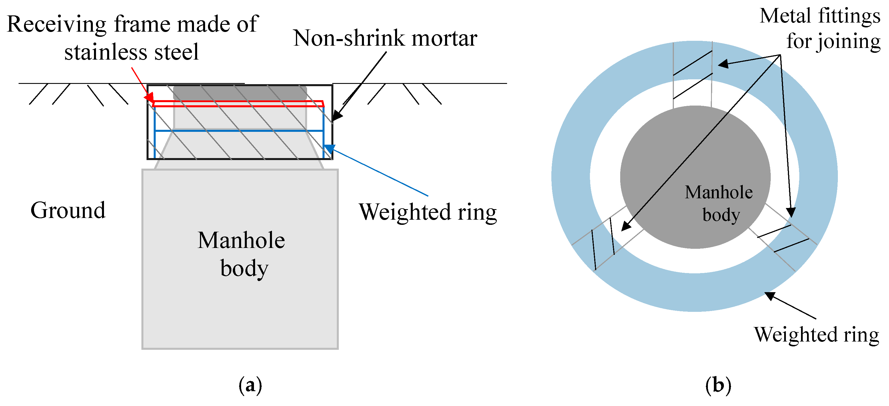
As shown in
Figure 2, a weighted ring is installed around the upper part of the manhole body, and a joint fitting is placed between the manhole body and the receiving frame where the manhole cover is installed. By joining the receiving frame and the manhole body via a joining member, the weighted ring and the manhole body are connected, and the space between the weighted ring and the manhole body is filled with non-shrink mortar and then floated by integration. The features of the weighting method are that it is low in cost, saves space due to its range in construction, causes no effect on buried objects, and that the weighted ring can be adjusted from one to three steps [
8].
3. Method for Evaluating Stability of Manholes during Liquefaction
3.1. Mechanism of Manhole Uplifting
Liquefaction of the ground is a phenomenon in which the loosely deposited saturated sandy ground receives repeated shear loads due to an earthquake or similar event, such that the pore water pressure between the sand particles increases and the shear resistance (effective stress) of the sand particles decreases. That is, the ground behaves like a liquid. When liquefaction occurs, sand boils (a phenomenon in which sand is blown up to the surface of ground) and fountains are seen, and the ground is compressed and subsides. Then, the fluidized backfill soil wraps around the bottom of the manhole, the frictional force on the peripheral surface of the manhole is reduced, and the (self-weight of manhole + frictional force on peripheral surface) becomes smaller than the uplifting pressure, causing manhole uplifting.
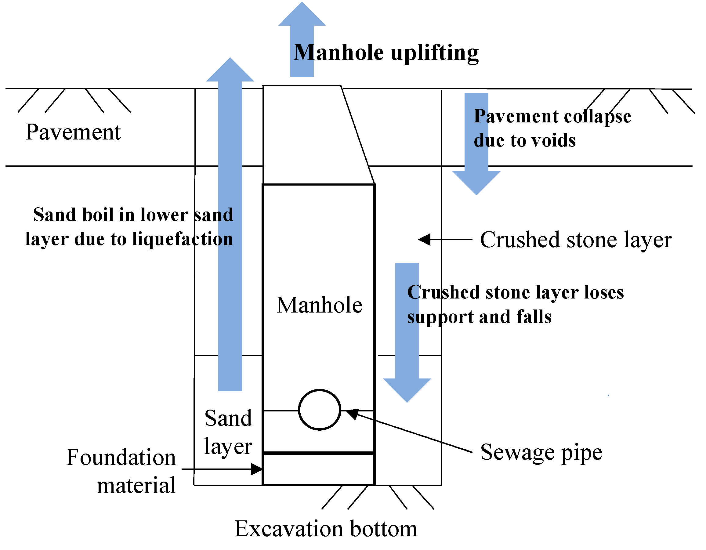
Figure 3 shows the mechanism of the occurrence of manhole uplifting due to liquefaction generated by an earthquake [
9,
10,
11,
12,
13,
14].
When the lower sand layer is locally liquefied, the upper crushed stone layer (fluidized backfill soil) loses its bearing capacity. Therefore, the upper crushed stone layer (fluidized backfill soil) and the pavement fall due to the loss of support from below, resulting in depressions in the ground surface. In addition, although it depends on the relationship between the depth of the manhole and the groundwater level, the manhole alone cannot maintain stability against buoyancy. Therefore, even if liquefaction does not occur, manhole uplifting may occur if the restraint from the surrounding ground is lost.
3.2. Safety Factor for Manhole Uplifting ()
When a manhole with a certain diameter exists from a predetermined depth to the surface of the ground, the safety factor (
) for manhole uplifting can be estimated using Equation (1).
where
is the safety factor for manhole uplifting,
is the load of overlaid soil on the surface of the ground,
is the self-weight of the manhole,
is the shear resistance of the overlaid soil,
is the frictional resistance on the side surface of the manhole,
is the uplifting pressure due to hydrostatic pressure loading on the bottom of the manhole, and
is the uplifting pressure due to excess pore water pressure loading on the bottom of the manhole.
3.2.1. Load of Overlaid Soil on Surface of Ground ()
The load of the overlaid soil on the surface of the ground (
) is the load of the soil to be placed on the upper part of the deck; this is estimated using Equation (2).
where
is the loading area (m
2),
is the layer thickness (m),
is the member volume (m
3) with respect to the layer thickness, and
is the unit volume weight of the soil (kN/m
3).
3.2.2. Self-Weight of Manhole ()
The self-weight of the manhole (
) is estimated with Equation (3) in consideration of the weight applied by the weighting ring.
where
is the weight of the manhole (kN) and
is the weight applied by the weighting ring (kN).
3.2.3. Shear Resistance of Overlaid Soil ()
The shear resistance (
) of the overlaid soil on the upper part of the deck is estimated from the total shear resistance in each layer for the overlaid soil; it is estimated with Equation (4).
where
is the coefficient of earth pressure at rest,
is the effective overburden pressure at the center of the layer (kN/m
2),
is the lateral surface area of the layer (m
2), and
is the internal friction angle (°). In principle,
for the overlaid soil is not considered in the liquefied ground; thus, the
of the liquefied ground (ground deeper than the groundwater level) is regarded as 0.
3.2.4. Frictional Resistance on Side Surface of Manhole ()
The frictional resistance force (
) on the side surface of the manhole is estimated from the total frictional resistance force on the side surface of the manhole in each layer using Equation (5).
where
is the lateral surface area of the manhole (m
2). In principle, the
on the side surface of the manhole is not considered in a liquefied ground; thus, the
of the liquefied ground (ground deeper than the groundwater level) is regarded as 0.
3.2.5. Uplifting Pressure Due to Hydrostatic Pressure Loading on Bottom of Manhole ()
The uplifting pressure on the bottom of the manhole (
), due to the hydrostatic pressure acting on it, is estimated using Equation (6).
where
is the unit volume weight of water (kN/m
3),
is the depth to the bottom of the manhole (m),
is the depth to the water table (m), and
is the area relative to the outer diameter of the manhole (m
2).
3.2.6. Uplifting Pressure Due to Excess Pore Water Pressure Loading on Bottom of Manhole ()
The uplifting pressure on the bottom of the manhole (
) due to excess pore water pressure loading is estimated using Equation (7).
where
is the excess ore water pressure (kN/m
3),
is the area relative to the outer diameter of the manhole (m
2),
is the effective loading pressure (kN/m
2) in the soil at the same depth as the bottom surface of the manhole under hydrostatic pressure, and
is the excess pore water pressure ratio. Excess pore water pressure ratio
is estimated with Equation (8) using the resistance value (
) against liquefaction [
4,
5].
In this study, is estimated based on the assumption that the ground is liquefied with a resistance value of < 1 against liquefaction.
The weighting method is a construction method in which the is estimated using the balance of forces in the vertical direction at the time of an earthquake, as described above, and the vertical load is increased by the self-weight of the manhole, such that the is equal to or greater than the predetermined value. Therefore, the physical significance is relatively clear.
This study adopted a value of 1.1 as the standard for evaluating the , because ≥ 1.1 is one of the design criteria for manholes set by the Japan Sewage Works Association (JSWA). The change in and the effect of the weighting method on are considered.
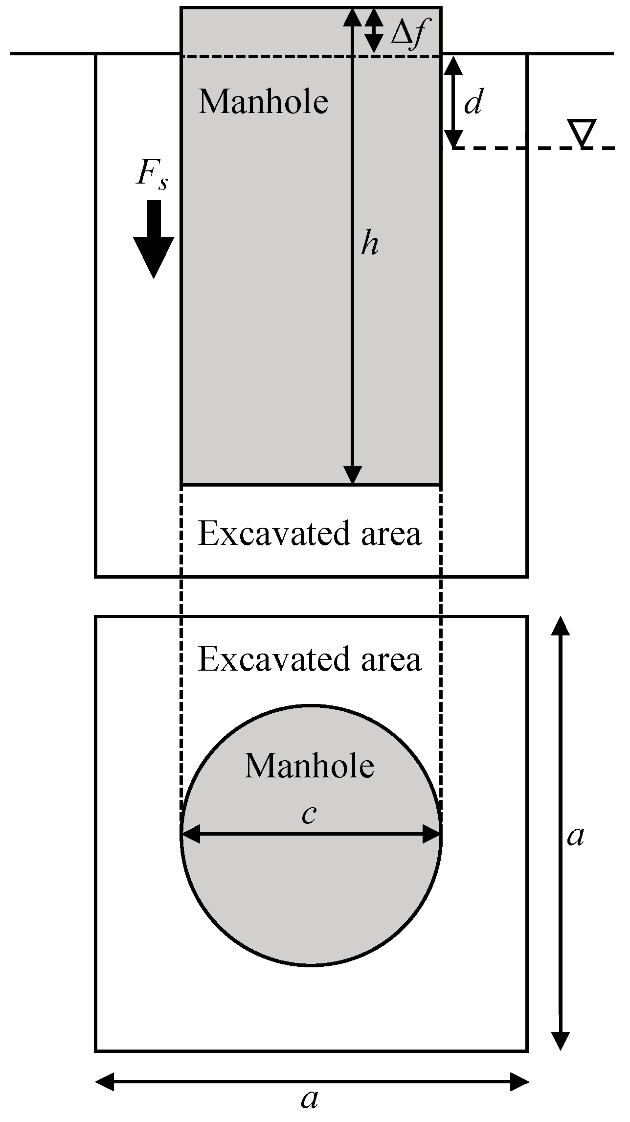
3.3. Quantity of Manhole Uplifting ()
The quantity (
) of manhole uplifting can be estimated using Equation (9) [
15], assuming that the backfill soil is completely liquefied, and the excavation range is sufficiently larger than the diameter of manhole, as shown in
Figure 4.
where
is the quantity of displacement for manhole uplifting,
is the manhole unit volume weight,
is the soil saturation unit volume weight,
is the vertical length of the manhole,
is the excess pore water pressure ratio,
is the unit volume weight of the non-liquefied soil layer shallower than the groundwater level,
is the depth of the groundwater level from the ground surface,
is the frictional force acting on the peripheral surface of the manhole, and
is the diameter of the manhole.
4. Stability Evaluation against Liquefaction
4.1. Analysis Patterns and Conditions
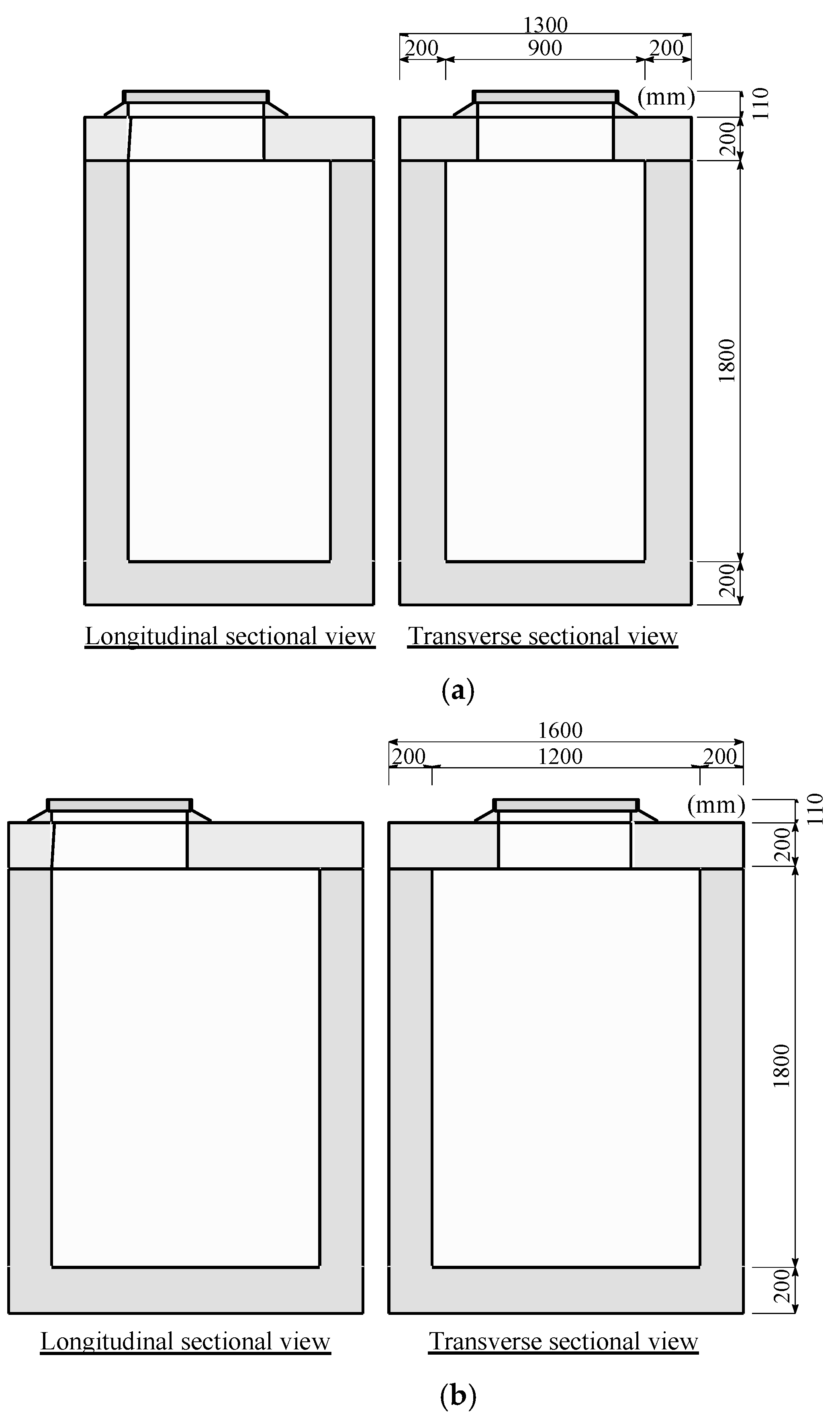
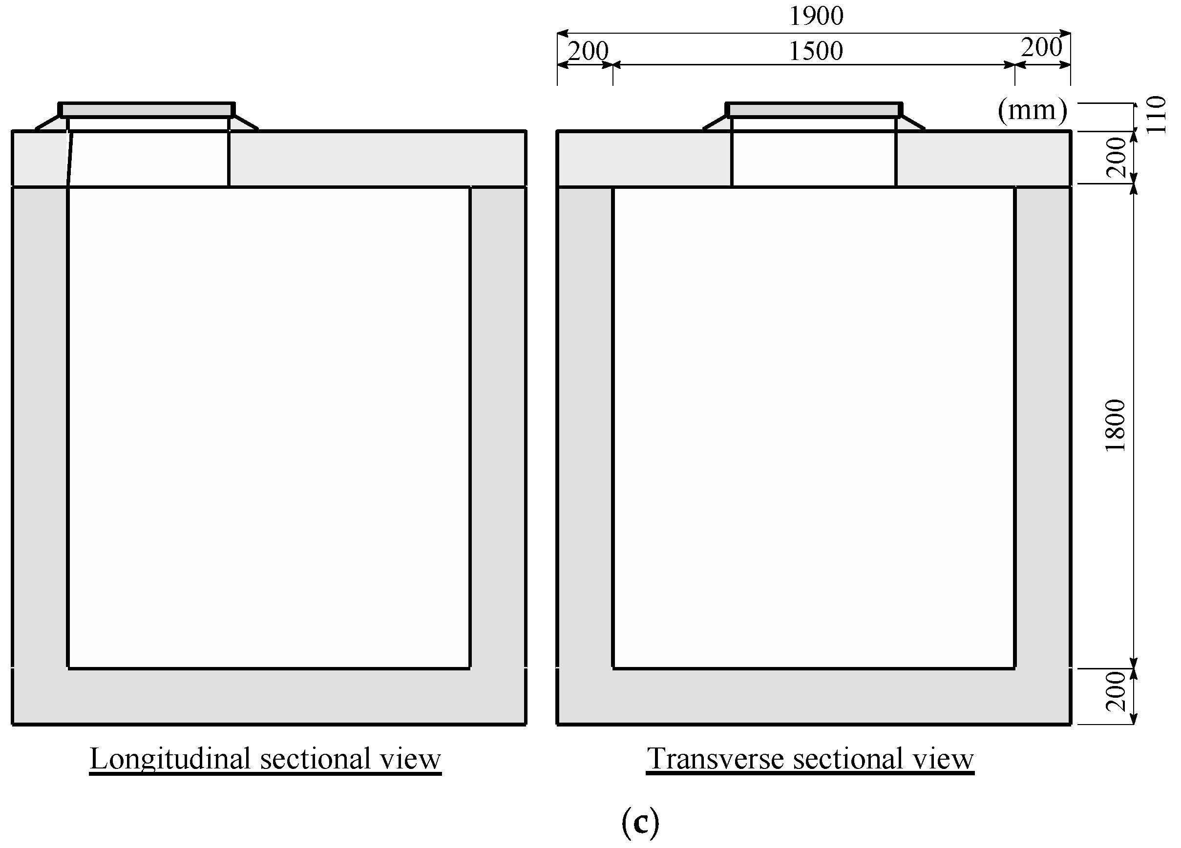
To make a comparison based on the manhole shape, the applicability of the weighting method will be examined using circular manholes, Nos. 1, 2, and 3, presented in
Figure 5 and
Table 1. The upper floor slab type is adopted as the shape of each circular manhole, and the analysis is performed on a saturated ground where the risk of liquefaction is high. In addition, for the No. 1 circular manhole, in order to examine the effect of the groundwater level in the ground around the manhole, the groundwater level is set to 0, 0.5, 1.0, 1.5, and 2.0 m, respectively.
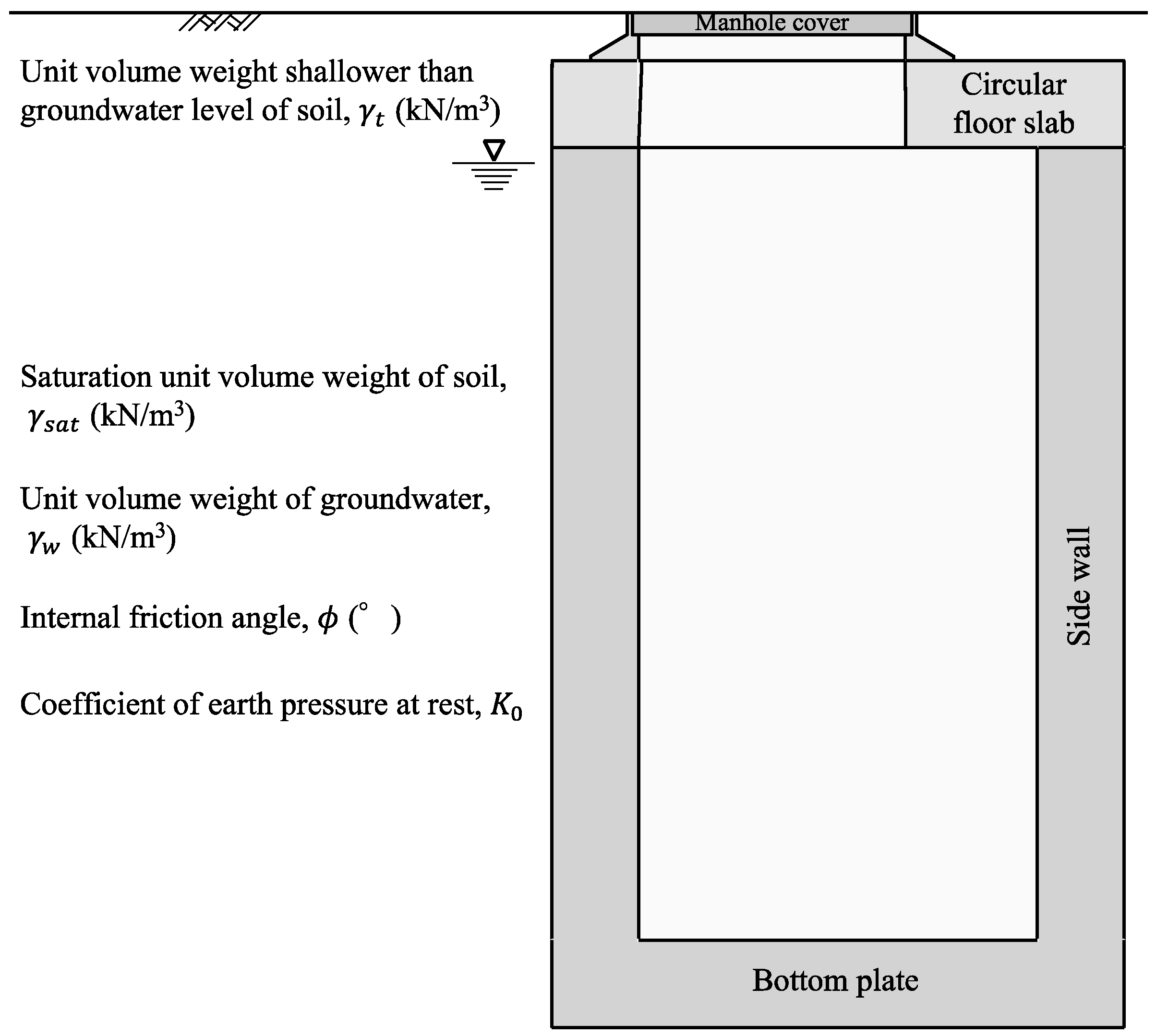
The analysis conditions for the manholes are set as given in
Table 2. The ground conditions around the manholes are shown in
Table 3. When calculating the
and the
, it is assumed that the ground around the manholes below the groundwater level was liquefied ground.
Figure 6 shows a schematic diagram of the analysis conditions.
4.2. Comparison by Manhole Shapes
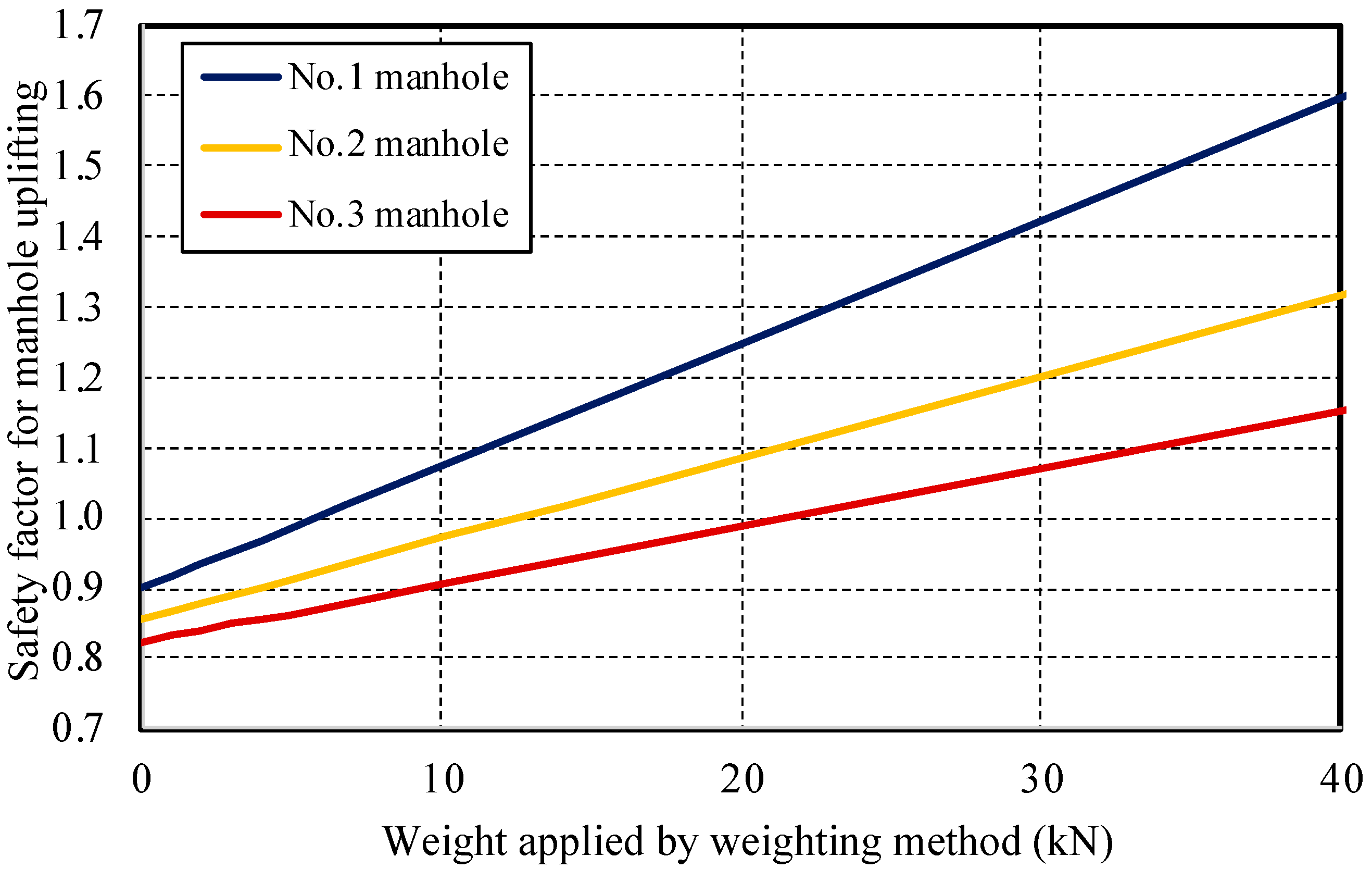
Figure 7 and
Figure 8 show the analysis results for the
and the
, respectively, of circular manholes Nos. 1, 2, and 3. When the weighting method is not applied to a manhole, the
is below 1.1, the standard for evaluating all shapes, and the
is also confirmed to be more than 0. In other words, not applying the weighting method creates an analysis condition with a very high risk of manhole uplifting when liquefaction occurs. In addition, the
increases and the
decreases as the weight applied by the weighting ring is increased in the weighting method for all shapes, so the weighting method can suppress the risk of manhole uplifting when liquefaction occurs. Moreover, the larger the manhole diameter, the higher the risk of manhole uplifting. By implementing the weighting method for a manhole in the ground where the manhole is likely to experience uplift when liquefaction occurs, the risk of manhole uplifting can be reduced regardless of the shape of the manhole.
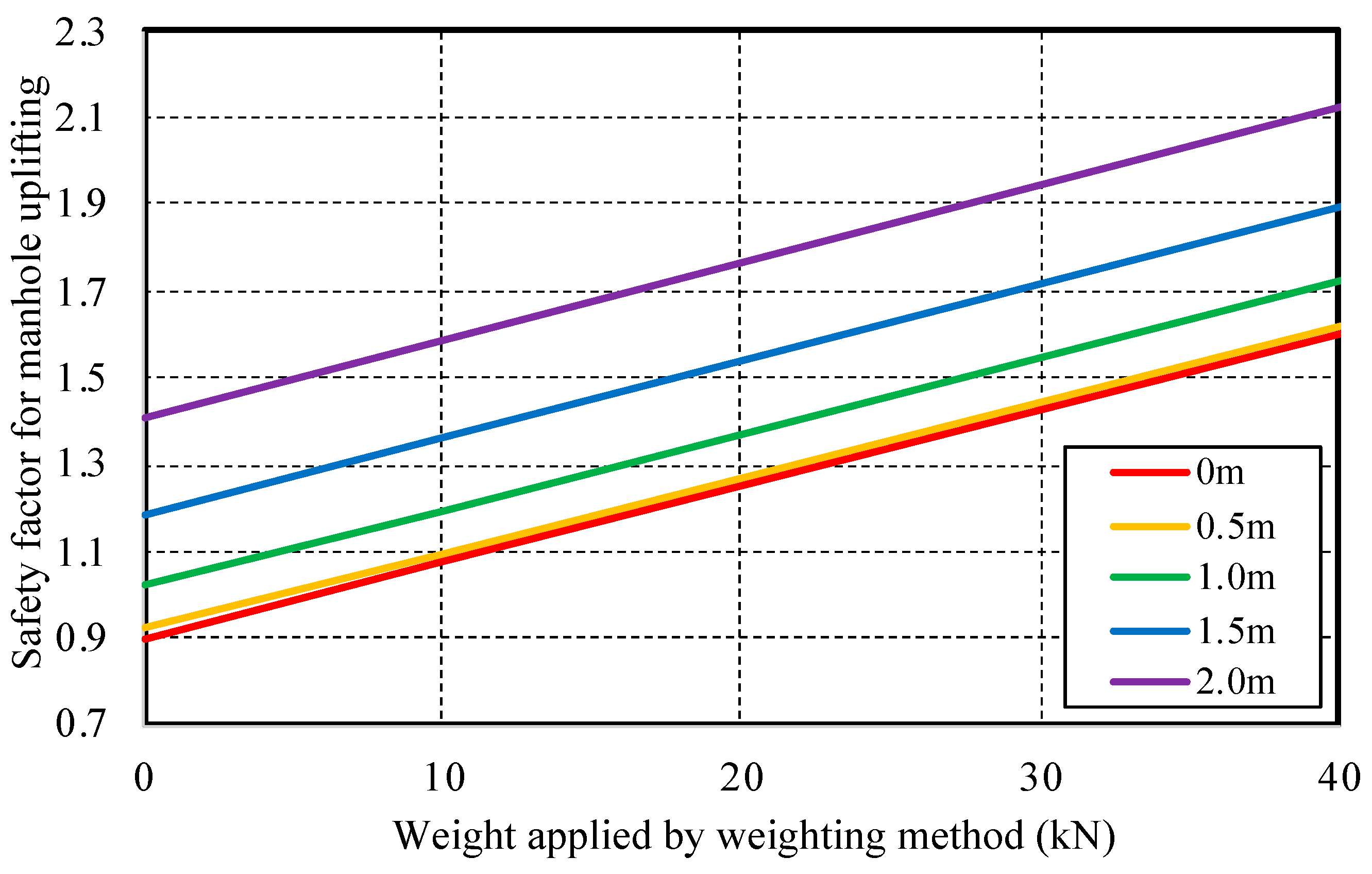
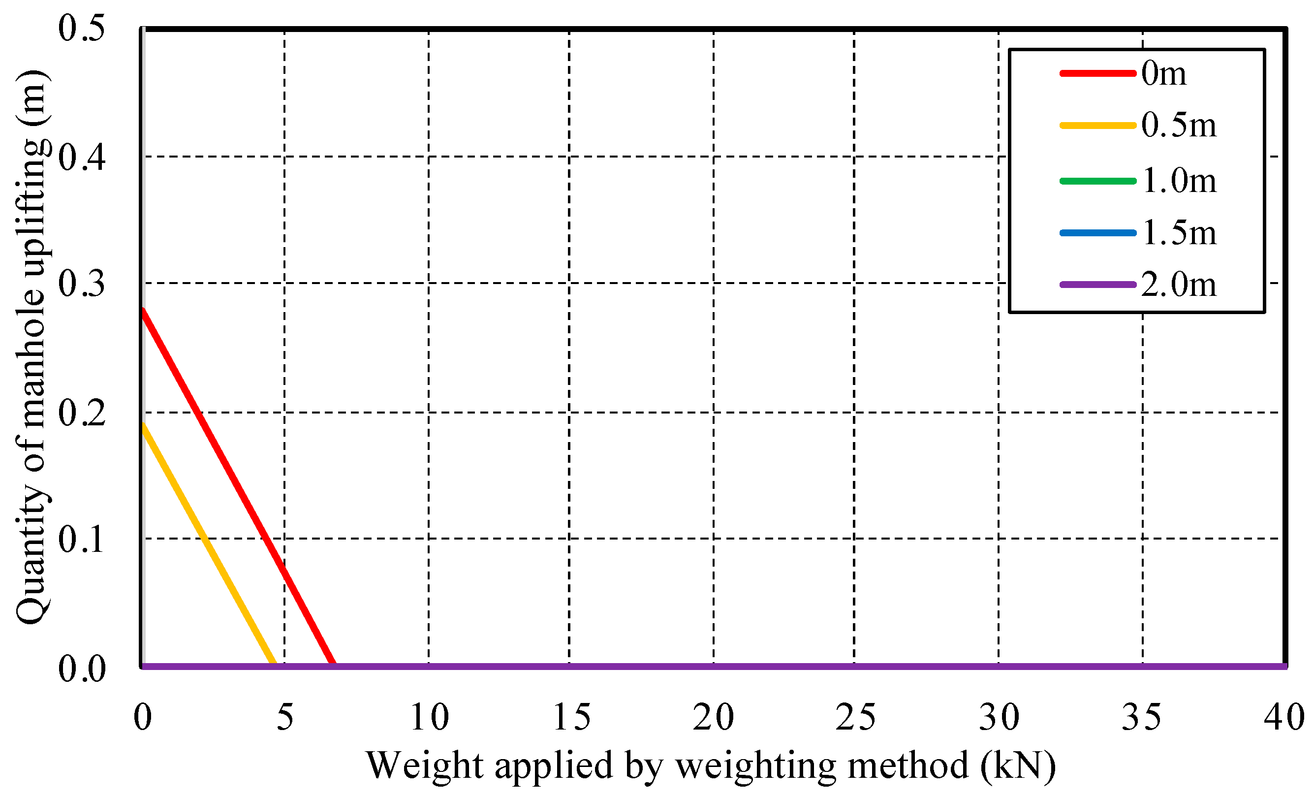
4.3. Comparison by Groundwater Level
Figure 9 shows the analysis results of the
for the No. 1 circular manhole when the groundwater level of the ground around the manhole is changed, while
Figure 10 shows the analysis results of the
for the No. 1 circular manhole when the groundwater level of the ground around the manhole is changed. It is confirmed that the
increased and the estimated
decreased as the groundwater level decreased. The major factors for this are considered to be the decrease in lifting pressure due to the decrease in the groundwater level and the effect of the generation of shear and frictional resistance below the groundwater level. In addition, the increasing rate of the
and the decreasing rate of the
, accompanying the increase in weight applied by the weighting ring, are almost equal at each groundwater level. The effect of the weighting method on manholes of the same shape is considered to be independent of the groundwater level. From the above, it is considered that the weighting method can reduce the risk of manhole uplift regardless of the groundwater level of the ground around the manhole.
5. Conclusions
In this study, the authors proposed and examined a weighting method as a countermeasure against the uplift of existing manholes due to liquefaction. The results obtained are as follows.
- (1)
Regardless of the shape of the manhole, by implementing the weighting method, the risk of manhole uplifting during liquefaction can be reduced.
- (2)
The weighting method can reduce the risk of manhole uplifting during liquefaction regardless of the groundwater level in the ground around the manhole.
It is thought that the weighting method is effective as a suppressive countermeasure against manhole uplifting due to the liquefaction of the ground around manholes. In countries where earthquakes occur frequently, it is indispensable to take measures against manhole uplifting brought about by the liquefaction of the ground around manholes. By applying the weighting method and adjusting the weight of the weighted ring according to the site conditions, it is possible to take the appropriate suppressive measures against manhole uplifting due to the liquefaction of the ground around manholes at each location. Minimum functionality must be ensured at sewerage facilities, including manholes, in the event of an earthquake or other natural disaster. In addition, it is necessary to take measures to prevent manhole uplifting so that such manhole uplifting does not interfere with rescue and disaster recovery activities in the event of such disasters.
Many measures against manhole uplifting due to liquefaction have been proposed, and the effects of each measure need to be clarified. Therefore, the application of each measure can be clarified not only by static analysis, but also by dynamic analysis. In addition, the ∆f during an earthquake changes greatly depending not only on the soil characteristics and vibration characteristics of the ground, but also on the groundwater level, excavation width, earthquake motion amplitude, vibration duration, and frequency characteristics. The process of the stability analysis in this study did not consider subsidence after manhole uplifting. Therefore, the ∆f may change depending on each individual case.
Author Contributions
Conceptualization, S.I.; methodology, K.N.; validation, H.Y.; formal analysis, K.N.; investigation, S.H.; resources, H.Y. and S.H.; data curation, K.N.; writing—original draft preparation, S.I.; writing—review and editing, S.I.; visualization, S.I.; supervision, S.I.; project administration, S.I. All authors have read and agreed to the published version of the manuscript.
Funding
This research received no external funding.
Institutional Review Board Statement
Not applicable.
Informed Consent Statement
Not applicable.
Data Availability Statement
Not applicable.
Conflicts of Interest
The authors declare no conflict of interest.
References
- Technical Committee on the Sewer Earthquake Countermeasures (TCSEC). Report of the Technical Committee on the Sewer Earthquake Countermeasures; Ministry of Land Infrastructure and Transport: Tokyo, Japan, 2005.
- Yasuda, S.; Kiku, H. Uplift of sewage manholes and pipes during the 2004 Niigataken-Chuetsu earthquake. Soils Found. 2006, 46, 885–894. [Google Scholar] [CrossRef] [Green Version]
- Yasuda, S.; Harada, K.; Ishikawa, K. Damage to structures in Chiba prefecture during the 2011 Tohoku-Pacific Ocean E-arthquake. Jpn. Geotech. J. 2012, 7, 103–115. [Google Scholar] [CrossRef] [Green Version]
- Japan Road Association (JRA). Guidelines on Road Earthwork/Retaining Wall Construction; Japan Road Association: Tokyo, Japan, 1999.
- Nan, T.; Xianyang, M.; Lin, L.; Liu, C.; Xiuhan, J. Manhole detection and location for urban pavement. In Proceedings of the 2003 IEEE International Conference on Intelligent Transportation Systems, Shanghai, China, 12–15 October 2003; Volume 2, pp. 1552–1555. [Google Scholar] [CrossRef]
- Lee, H. Structural optimization of a light-weight manhole cover using FEM and response surface method. J. Korean Soc. Manuf. Technol. Eng. 2016, 25, 462–470. [Google Scholar]
- Matsuhashi, M.; Tsushima, I.; Fukatani, W.; Yokota, T. Damage to sewage systems caused by the Great East Japan Earthqua-ke, and governmental policy. Soils Found. 2014, 54, 902–909. [Google Scholar] [CrossRef] [Green Version]
- Nakao, K.; Yamaguchi, H.; Hoshino, S.; Nagai, K.; Inazumi, S. Development and applicability of weighting method as a countermeasure against liquefaction uplifting of existing manholes. In Proceedings of the Japan Society of Civil Engineers 2021 Annual Meeting 2021, VI-111, Kanagawa, Japan, 8–10 September 2021. [Google Scholar]
- Koseki, J.; Matsuo, O.; Koga, Y. Uplift behavior of underground structures caused by liquefaction of surrounding soil during earthquake. Soils Found. 1997, 37, 97–108. [Google Scholar] [CrossRef]
- Koseki, J.; Matsuo, O.; Ninomiya, Y.; Yoshida, T. Uplift of sewer manholes during the 1993 Kushiro-oki earthquake. Soils Found. 1997, 37, 109–121. [Google Scholar] [CrossRef] [Green Version]
- Yasuda, S.; Nagase, H.; Itafuji, S.; Sawada, H.; Mine, K. Shaking table tests on floatation of buried pipes due to liquefaction of backfill sands. In Proceedings of the 5th U.S.-Japan Workshop on Earthquake Resistant Design of Lifeline Facilities and Coun-termeasures against Soil Liquefaction, Utah, The United States of America, Tokyo, Japan, 29 September–1 October 1994; pp. 666–677. [Google Scholar]
- Yasuda, S.; Nagase, H.; Itafuji, S.; Mine, K. Floatation of buried pipes due to the liquefaction of backfilled sands. In Proceedings of the 10th Asian Regional Conference on Soil Mechanics and Foundation Engineering; 1995; pp. 509–512. [Google Scholar]
- Yasuda, S.; Nagase, H.; Itafuji, S.; Sawada, H.; Mine, K. A study on the mechanism of the floatation of buried pipes due to liquefaction. In Proceedings of the 7th International Conference of Soil Dynamics and Earthquake Engineering, Crete, Greece; 1995; pp. 125–132. [Google Scholar]
- Grasso, S.; Massimino, M.R.; Sammito, M.S.V. New stress reduction factor for evaluating soil liquefaction in the coastal area of Catania (Italy). Geosciences 2021, 11, 12. [Google Scholar] [CrossRef]
- Tobita, T.; Iai, S.; Kang, G.C.; Konishi, Y.; Harazono, S. Simplified Method for Estimation of the Maximum Uplift Displacement of a Manhole during Earthquakes, Annuals of Disaster Prevention Research Institute; Kyoto University: Kyoto, Japan, 2009; Volume 52, pp. 355–364. [Google Scholar]
| Publisher’s Note: MDPI stays neutral with regard to jurisdictional claims in published maps and institutional affiliations. |
© 2022 by the authors. Licensee MDPI, Basel, Switzerland. This article is an open access article distributed under the terms and conditions of the Creative Commons Attribution (CC BY) license (https://creativecommons.org/licenses/by/4.0/).


