Abstract
Magnetic gear mechanisms have advanced to have a promising future in transmission technology. Previous research indicates that magnetic gear mechanisms might replace mechanical gear mechanisms in some applications. Small-scale wind turbines (SWT) with counter-rotating rotors that were initially fitted by bevel gears are proposed to be replaced by a coaxial magnetic gear train (CMGT). The CMGT is intended for use as a speed multiplier in order to obtain maximum power at low wind speeds, due to its beneficial transmission of power without physical contact. The primary objective of this study is to build a dual-input CMGT that will be employed in the transmission system of small-scale counter-rotating wind turbines. A dual-input CMGT is built through the analytical modeling of an equivalent magnetic circuit (EMC), which aims to predict the magnetic flux density in the air-gaps of CMGT. Several models within design constraints were compared to obtain the optimum design parameters of the preliminary CMGT design resulting from an EMC analysis. The optimized critical design parameters were then selected and analyzed using finite-element analysis (FEA) to depict the performance of the proposed SWT design. According to the findings, the developed design can generate an inner air-gap flux density of 0.8314 T and an outer air-gap flux density of 1.0200 T. The model likewise produces promising simulation results with an output transmitted torque in the inner rotor (output link) of 8.7 Nm, 56.9 Nm in the outer rotor, and 48.0 Nm in the carrier with pole-pieces. Thus, this design can generate higher torque than a bevel-geared wind turbine. The speed characteristics are also compromised in order to raise the generator’s rotating speed to generate more power. Finally, this study demonstrates the performance and embodiment design of the proposed SWT using CMGT.
1. Introduction
The need to develop environmentally friendly technology comes from two critical issues: climate change; and the need to limit the use of non-renewable energy sources. As the use of coal impacts pollution levels in the air, it also affects climate change. Both issues are related. If the use of fossil energy can be reduced, it will also impact the reduction of pollution. Thus, the development of environmentally friendly and sustainable technology needs to be undertaken by utilizing renewable energy sources, such as power plants. Small-scale wind turbines (SWT) can produce electricity below 100 kW [1]. Researchers have carried out development work on SWT designs. Various designs have been adapted to the needs of the areas where they are installed. This type of wind turbine has a simple mechanical structure compared to large-scale wind turbines. The structure entails a lower purchase price, is lightweight, has fewer space constraints and is easy to mount [2]. Furthermore, some wind turbine manufacturers have also produced multiple types of SWTs. The ideas for developing SWTs are as patented by Asfar [3] and Wacinski [4]; the aim is to increase the power supply by employing two rotors. Both patents show their designs equipped with mechanical planetary gear trains. For Wacinski’s design, two counter-rotating propellers are connected to the ring gear and carrier, respectively, of a 2-degrees-of-freedom (2-DOF) basic planetary gear train to generate the largest angular speed of the sun gear connected to the generator. The efficiency of the dual rotor wind turbine is better than that of single construction [4]. Other than that, a smaller generator can be installed into the dual rotor wind turbine compared to the single one [4]. Another researcher examined a counter-rotating wind turbine which can increase power production by up to 25% [5].
Compared to existing mechanical gearboxes used for wind turbines, magnetic gear mechanisms offer new opportunities to build new-concept wind turbines. Magnetic gears are used to replace mechanical gears because the gearbox generates turbine stop hours as 42% [6]. Furthermore, the gearbox also causes power losses in a wind system (composed of a generator, converter, and gearbox). This power loss occurs because a machine generates shallow power for wind speeds of less than 4 m/s, such as off-the-shelf wind systems [7]. The authors chose to design a magnetic gear mechanism because it has the advantage of transmitting power without physical contact. The other benefits are less vibration and noise, no need for lubricant and maintenance, and unique characteristics of torque-overload protection [8,9]. Unlike mechanical gears, magnetic gears will not fail in the overload condition of transmitted torque [10]. The use of NdFeB permanent magnet material can provide high energy density, durable magnetization, and high conductivity [11]. The magnetic gear topology widely discussed is the coaxial magnetic gear train (CMGT) because of its compact size, high torque density, and manufacturing possibilities. Despite those advantages, CMGT has some drawbacks. The mechanical complexity of the magnetic gears is one of the drawbacks of CMGT, especially for the complex mechanical structure of the carrier. The mechanical construction is challenging because the components are concentric and move in different angular velocities. The rotor components will slip when the torque overload occurs and cannot transmit power, which may have security concerns if used in the transmission systems of mobile vehicles. However, this disadvantage becomes an advantage of magnetic gears used in the transmission systems of wind turbines, because it can protect the mechanism from overload failure. Another disadvantage of CMGT is that the permanent magnet will demagnetize when the overheat occurs. Despite these disadvantages, a the magnetic gear mechanism has been successfully developed in the continuous variable transmission; the prototype uses a 2-DOF CMGT [12]. SWT development with a CMGT is expected to become a novel and useful invention for academic study and engineering applications. Thus, an eco-friendly technology that directly utilizes potential energy resources can be developed and could offer a useful advantage and a possible solution to the problems mentioned above.
The main goal of this paper is to design a dual-input CMGT to be used as the transmission system of small-scale counter-rotating wind turbines. The design steps are introduced, including the topology definition of CMGT and the selection of the design parameters. Next, the analytical modeling of the equivalent magnetic circuit (EMC) is discussed. This analytical approach aims to predict the magnetic flux density in the air-gaps of CMGT. When the mathematic model is validated, the parameter constraints are then determined and investigated to derive the optimum design parameters of the preliminary CMGT design. The optimized critical design parameters are then selected and combined with the unchanged preliminary parameters. Section 3 deals with the computational simulation results of the magnetostatic field, the magnetic flux density in the air-gaps, the transmitted torque and the rotational speed of the presented CMGT. The finalized design parameters are summarized, and the embodiment design of the SWT is also presented. The conclusions are offered in Section 4.
2. Coaxial Magnetic Gear Train (CMGT)
There are various magnetic gear mechanism topologies. The CMGT, i.e., a flux-modulated magnetic gear mechanism with coaxial topology, has been developed rapidly in recent years. Most of the designs focus on the torque density achieved by changing their topologies. Furthermore, to obtain the optimum scheme of the CMGT model, Zhao et al. [13] proposed an analytical model considering magnetic saturation. In order to support an understanding of the working principle of the CMGT. some equations are then discussed [14,15].
The CMGT consists of four mechanical parts: a frame, two rotors mounted with a different pole pairs number of permanent magnets, and a carrier with ferromagnetic pole-pieces sandwiched between two rotors. The inner permanent magnets are mounted on the outer surface of the inner rotor with a high rotational speed. The ferromagnetic pole-pieces are arranged in carrier slots. The outer permanent magnets are mounted on the inner surface of the outer rotor, which has a slow rotational speed. The inner rotor, carrier, and outer rotor are separated by the inner and outer air-gaps. From this configuration, the modulation effect caused by the pole-pieces is a vital part in transmitting torque from the input link, and driving the output link at a specific rotational speed. The detailed depiction of the CMGT topology is shown in Figure 1.
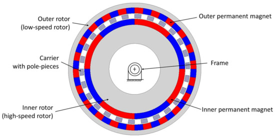
Figure 1.
Cross-sectional view of CMGT.
The numbers of magnet pole pairs of the inner and outer rotors, and the number of pole-pieces on the carrier can be determined by Equation (1) [8]:
where pi is the number of magnet pole pairs on the inner rotor, po is the number of magnet pole pairs on the outer rotor, and Nc is the number of ferromagnetic pole-pieces on the carrier. Obtaining the magnet pole-pair number affects the gear ratio of the CMGT. The kinematic relationship of the inner rotor, the carrier, and the outer rotor of the CMGT can be expressed as Equation (2) [9]:
where is the rotational speed of the inner rotor, is the rotational speed of the outer rotor, and is the rotational speed of the carrier.
Nc = pi + po,
pi ωi − Nc ωc + po ωo = 0,
3. Design of a CMG for SWT
A step-by-step design process for implementing a CMGT used for SWT is presented in Figure 2. Each design step is described in detail in the following subsections.

Figure 2.
Design process of CMGT used for SWT.
3.1. SWT and CMGT Topology Definition
An existing SWT, which is a 500 W counter-rotating wind turbine from Ilmunandar and Bramantya [16], was used for the installation of the CMGT. The CMGT shown in Figure 1 is a 2-DOF mechanism; two independent inputs are required to obtain a predictable output. When the outer rotor and carrier of the CMGT are assigned as the two input links and connected to the counter-rotating blades, the inner rotor will be the output link connected to the generator. Based on Equation (2), the inner rotor obtains the highest rotational speed, as shown in Equation (3):
In this situation, the CMGT is a speed multiplier with the highest speed ratio, defined as the output shaft speed ratio to the input shaft speed. When the two blades rotate with identical rotational speed, but in the opposite direction for a counter-rotating wind turbine, the speed ratio of the CMGT is equal to (Nc + po)/pi. The detailed design specifications of the CMGT are listed in Table 1.

Table 1.
Design specifications of the CMGT.
3.2. Preliminary Design Selection
In the research undertaken by Shah et al. [14], the 22 magnet pole pairs on the outer rotor successfully produced the greatest amplitude of space harmonics when the magnet pole pairs on the inner rotor was 4. Therefore, from Equation (1), the pole-pieces on the carrier have to number 26. Due to the available space of the CMGT shown in Table 1, the outer diameter and axial length of the outer rotor are set as 140 mm and 30 mm, respectively. The inner diameter of the inner rotor is the same size as the generator’s shaft, which is 54 mm. The inner and outer air-gap length is set at 1 mm due to the ease of the manufacturing and assembly process. If the length is less than 1 mm, it would be difficult to assemble due to dimensional tolerance, even though the shorter length would make a positive contribution to the magnetic flux density and the transmitted torque. The detailed preliminary design parameters of the CMGT are shown in Table 2 and Figure 3.
Table 2.
Preliminary design parameters of a CMGT.
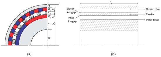
Figure 3.
Design parameters of the CMGT: (a) Sectional view; (b) Axial view.
3.3. Equivalent Magnetic Circuit (EMC) Modeling
The equivalent magnetic circuit (EMC) was selected to provide an analytical overview of the magnetostatic field of the CMGT, especially for the magnetic flux density in the air-gap. Using EMC modeling, the calculating time will become faster than the finite-element simulation [17]. Besides, the EMC model provides enough insight and clear relationships among the geometric dimensions, magnet material properties, and magnetostatic field, which is suitable for the preliminary design of a CMGT. Two assumptions for the EMC model to simplify the analysis are as follows:
- There is no magnetic saturation occurring in the CMGT;
- The rotor back iron has infinite permeability compared with the air-gap.
Due to the geometrical symmetry of a CMGT, it is only necessary to model one such pair [18], as shown in Figure 4a. The outer rotor and inner rotor steel areas are modeled as magnetic reluctance Ror and Rir, respectively. The permanent magnets on the outer rotor and inner rotor are modeled as the magnetic flux sources φor and φir, respectively, and as magnetic reluctance Rm1 and Rm2, respectively, with the direction of the source dictating the magnet polarity. The air-gaps g1, g2, and g3 are considered as magnetic flux tubes with magnetic reluctance Rg1, Rg2, and Rg3, respectively. The magnetic reluctance of the pole-piece on the carrier is modeled as Rp, whereas the reluctance modeling the leakage fluxes in the inner magnets, outer magnets and pole-pieces are Rli, Rlo and Rlm, respectively. The related equivalent magnetic circuit is shown in Figure 4b. Figure 5 shows the simplification of the EMC. In Figure 5a, ϕ, ϕl1, and ϕl2 represent the magnetic flux leaving the magnet, flux leakage in the outer air-gap, and flux leakage in the inner air-gap, respectively. The magnetic flux in the outer and inner air-gaps can be written as ϕg1 = Kl1ϕ and ϕg2 = Kl2ϕg1, where Kl1 and Kl2 represent leakage factors in the outer and inner air-gaps. The leakage factors are typically less than one [19].
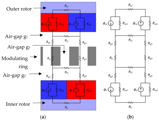
Figure 4.
EMC modeling: (a) one pair magnet modelled, (b) modelled circuit.
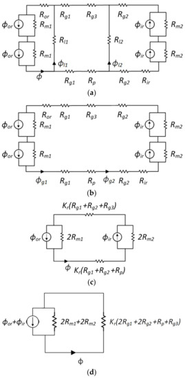
Figure 5.
Simplification of unit block circuit: (a) swapping the Ror and Rir, (b) eliminating the magnet and leakage reluctances, (c) eliminating the Ror and Rir, (d) swapping and simplifying the circuit.
Moreover, the circuit is simplified by eliminating the leakage reluctance, as shown in Figure 5b. The leakage reluctance is eliminated because the distribution ranges of the magnetic leakage fluxes are always very small. Hence, the leakage reluctance of the magnet poles is much larger than the internal reluctance of the magnet poles [20]. Therefore, it is difficult to express the Rl1 and Rl2. In order to obtain the ϕgn, the solution for φ will be multiplied by an estimation of Kl between 0.8 to 0.9 [21] to compensate for the flux that follows the leakage path. When the leakage reluctance is eliminated, the magnetic reluctance is in series to be lumped. The outer rotor and inner rotor reluctance Ror and Rir, which are eliminated, as shown in Figure 5c, are modeled as a perturbation of the air-gap reluctance by introducing a reluctance factor Kr with its value between 1 to 1.2 [19].
The elimination is due to the assumption of infinite permeability of the outer and inner rotor iron yoke. Figure 5c depicts the simplified circuit with the Kr notation. Two half magnets connected in series are equivalent to a single block of permanent magnet material twice as long. As a result, ϕor and ϕir remain constant while Rm1 and Rm1 double because reluctance is directly proportional to magnet length [19]. Finally, the magnets and rotor reluctance are swapped, as shown in Figure 5d.
As mentioned in [19], the analytical expressions for the leakage factor Kl and reluctance factor Kr are seldom tried. These expressions are difficult to determine accurate values; that is why the amount of Kl and Kr used for this study was identified as discussed before.
The magnet flux can be obtained using flux division, as in Equation (4):
The general reluctance is expressed in Equations (5)–(7):
In these equations, lmn, Amn, lp, Ap, gn, Agn are the magnet length, axial magnet area, pole-piece length, pole-piece axial area, air-gap length, and air-gap axial area, respectively, whereas n = 1, 2, 3. Moreover, μr and μ0are relative permeability and permeability of free space, respectively. Furthermore, the flux density relationships are: Bg1 = ɸg1/Ag1, Bg2 = ɸg2/Ag2, and Br = ɸor/Am1 = ɸir/Am2. The Br of the two magnets is the same value because the magnetic gear uses the same permanent magnet material. Hence, the outer and inner air-gap flux density is determined as in Equations (8) and (9), respectively:
Three cases are taken as examples to calculate the flux densities of the inner and outer air-gaps by EMC model. The design variables are the thickness of the permanent magnet on the outer and inner rotors B and D, the thickness of the pole-piece C, the radial length of the inner rotor iron yoke E and the diameter of the inner rotor D, as shown in Table 3. Other design parameters of the CMGT are kept constant. These three cases refer to Wu et al. [22]. These cases are chosen because of their transmitted torque values, length, and thickness parameters, which are roughly more similar to other models. Therefore, even the Di value is different, and the parameters are reasonable since the Do, as the key parameter of the design space, remains unchanged. Table 4 shows the analytical results of the outer and inner air-gap flux densities, i.e., Bg1 and Bg2, of three CMGTs by the EMC model.
Table 3.
Three cases of CMGTs.
Table 4.
Magnetic circuit analysis of three CMGTs by EMC model.
3.4. Model Validation by FEA
To verify the feasibility of the proposed EMC model, the FEA was applied to assist in simulating the magnetostatic field of the CMGT and making a quantitative comparison with the analytical results. The ANSYS/Maxwell 2D field simulator was employed for the magnetic field analysis of the two-dimensional CMGT configuration. Figure 6a presents the flux density distribution of the case 1 CMGT, while Figure 6b,c demonstrate the outer and inner air-gap flux density waveforms, respectively.
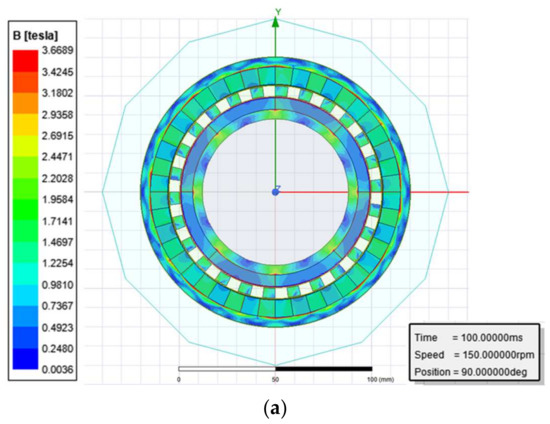

Figure 6.
Magnetostatic field analysis of case 1 of the CMGT by FEA: (a) flux density distribution, (b) outer air-gap waveform, (c) inner air-gap waveform.
The air-gaps’ flux densities were measured using ANSYS/Maxwell simulation. In the inner air-gap, the circle was drawn in the middle of the inner air-gap to obtain the flux density. Since the air-gap length is 1 mm, the circle is drawn in the 0.5 mm between the outer diameter of the inner permanent magnets and the inner diameter of the carrier. The circle is then set as the path to depict the flux density in the inner air-gap. With the data shown in the graphic, and the numerical results collected, the average value of the flux density can be measured. Accordingly, the same procedure was applied in the outer air-gap to generate the flux density in the outer air-gap.
Table 5 shows the errors of the outer and inner average air-gap flux densities by comparing the EMC results with the FEA results. The highest error of the EMC model in these three cases was 10.4% because the EMC model proposed in this study is a one-dimensional EMC. In contrast, the ANSYS/Maxwell simulation analyzes at least a two-dimensional model. Many factors were neglected for the EMC. However, the EMC model is sufficient for the optimization method since it can depict the value of the designed investigation.
Table 5.
Comparison of the air-gap flux density for EMC and FEA results.
Finally, the analytical equations are confirmed with the finite-element analysis simulation method. The mathematical modeling is valid, so the equations can then be used to determine the magnetic gear parameter of a magnet and pole-piece length.
3.5. Parameter Determination
The transmitted torque of a CMGT is highly dominated by its magnetostatic field distribution, especially for the magnetic flux densities in the outer and inner air-gaps. Hence, this study applied the magnetic flux densities in the outer and inner air-gaps as the objective function to discover the optimum value. The objective function transforms into a function that maximizes the magnetic flux density, as shown in Equation (10). The addition of the outer and inner rotor magnetic flux densities aims to have their maximum flux density:
Six parameters were then chosen as the variables:
where R1 and R2 are the outer and inner radius of the outer rotor permanent magnet, respectively, while the outer and inner radii of the flux modulator are denoted as R3 and R4, respectively, and the outer and inner radius of the inner rotor permanent magnet are denoted as R5 and R6, respectively. Those six variables are the parameters that can be changed to derive the optimum flux density in the proposed design. After randomly changing the value and calculating the flux density, the best combination will be determined as design parameters.
The constraints are set as follows to derive a value of those variables that does not cause any conflict, due to the radius characteristic, which otherwise must be set as a different number. Equation (10), as the objective function, depends on Equations (12)–(18), which require some geometry parameters. The 4 (four) in the constraints signifies the minimum magnet size due to manufacturing possibilities. If the size is less than 4, it is difficult to fabricate. Because the outer diameter of the CMGT should be 140 mm and the outer iron part set to greater than or equal to 5 mm, the value of 65 appears to limit the maximum radius of R1. The inner iron part’s size is also set at 5 mm, so R6 should be greater than or equal to 43 to keep the inner diameter at 76 mm.
R1 ≤ 65,
R2 < R1 − 4,
R3 = R2 − 1,
R4 < R3 − 4,
R5 = R4 − 1,
R6 < R5 − 4,
43 ≤ R6
Some of the parameters have been mentioned above; the other geometry parameters of magnetic gear can be seen in Table 6. This geometry value will be the initial parameters of this parameter determination.
Table 6.
Value of geometry parameters.
The random approach is used because the constraints that need to be set for the prototype are specific. The value of the variables is limited to ensure its manufacturing possibility. From the variable constraints, the objective function can be linearly solved. Therefore, the random approach is sufficient to find out the optimum combination to be determined as the parameters of the proposed design.
The analytical calculation process is performed using MATLAB to achieve the optimum flux density. The geometry parameters shown in Table 6 were used as inputs for the analytical calculation. The variables and constraints were then randomly combined and analyzed. The best variable combination can be achieved after the flux density has reached its optimum value.
After going through the above processes, the value of each variable and the flux densities were obtained, as shown in Table 7. Only ten combinations are shown in the table, representing the calculation results. From the table, the best value is 1.9387 T, with the value of Bg1 being 1.0220 T, and Bg2 being 0.9167 T. Finally, the parameters were determined based on the calculation process’s best result in Table 8. This result was then selected as the final parameters of the magnetic gear to be designed.
Table 7.
The analytical calculation results.
Table 8.
Optimum parameters.
The computational analysis in this study is limited to the magnetic gear design only. The proposed magnetic gear design was analyzed using ANSYS/Maxwell software to depict the magnetostatic field, air-gap flux density, torque, and rotational speed.
- (a)
- Magnetostatic Field
The optimum magnetic gear parameters shown in Table 8 were simulated using ANSYS/Maxwell. The analysis result of the magnetostatic field can be seen in Figure 7. Figure 8 shows the magnetic flux lines.
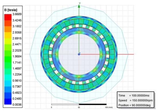
Figure 7.
Magnetostatic field.
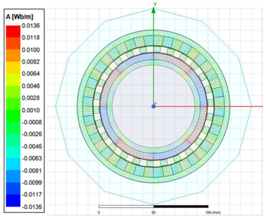
Figure 8.
Magnetic flux lines.
- (b)
- Magnetic Flux Density
The magnetic flux density in the outer air-gap can be seen in Figure 9. Figure 10 shows the magnetic flux density in the inner air-gap. The average of those magnetic flux densities from the two-dimensional simulation is 1.0200 T and 0.8314 T for outer air-gap and inner air-gap flux density, respectively. Compared to the analytical result, the outer air-gap magnetic flux density error is −0.2%, and the inner air-gap magnetic flux density error is −10.3%.
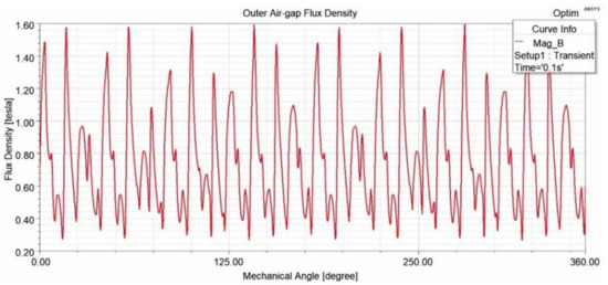
Figure 9.
Outer air-gap flux density.

Figure 10.
Inner air-gap flux density.
- (c)
- Transmitted Torque
The maximum transmitted torque based on the simulation result is 8.7 Nm in the inner rotor, which is the output of the gearbox. The maximum torque in the outer rotor and the pole-piece is 56.9 Nm and 48.1 Nm, respectively. The torque graphic can be seen in Figure 11. Compared to the wind turbine [15], the proposed small-scale wind turbine shows that the CMGT can transmit higher torque than the bevel-gearbox wind turbine.
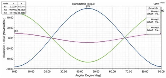
Figure 11.
Transmitted torque.
- (d)
- Rotational Speed
Figure 12, Figure 13, Figure 14 and Figure 15 show the rotational speed of the proposed magnetic gear. Four simulations were carried out to obtain the rotational speed overview of wind turbines in a different situation. The inner rotor has set simulions as moving 1, pole-piece as moving 2, and outer rotor as moving 3. In the first simulation, all the motions were set to consider the mechanical transient. The rotational speed is presented in Figure 12. With this rotation as the input from the wind, motion 3 can rotate up to 823.7 rpm. It means that the rotational speed of the generator can rapidly increase. Second, motion 2 is set as a constant. It is set at 25 rpm, as examined by previous research. The rotational speed graphic can be seen in Figure 13. In the third simulation, motion 1 is set as a constant to obtain a different speed combination of the primary and secondary input. When the inner rotor rotates at 500 rpm, the outer rotor rotates at 75.8 rpm so that the pole-piece rotates at 12.5 rpm, as shown in Figure 14. The last simulation depicted in Figure 15 shows the constant speed for motions 2 and 3. The rotational speed simulation result shows the gearbox’s capability of variable gearing ratios, which are close to the theoretical equation (Equation (3)). It also shows the possibility of increasing the gearbox rotational speed to produce more electric power.
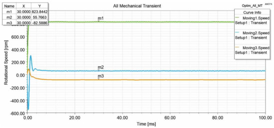
Figure 12.
Rotational speed when all the motions are set to consider the mechanical transient.
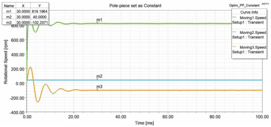
Figure 13.
Rotational speed when the pole-piece set as constant.
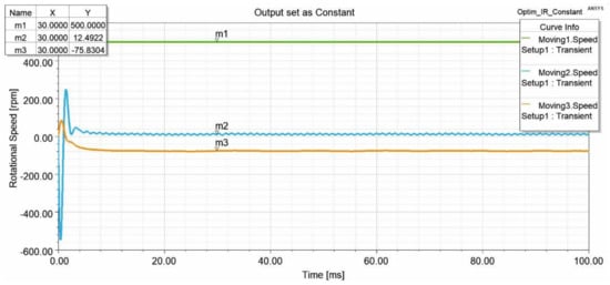
Figure 14.
Rotational speed when the inner rotor (output) is set as constant.
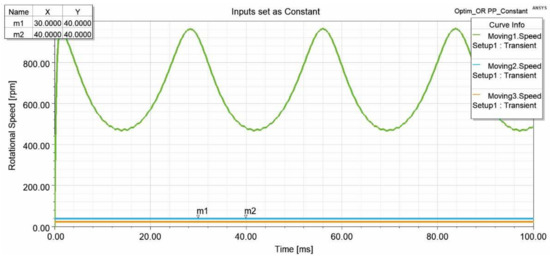
Figure 15.
Rotational speed when the outer rotor and pole-piece set as constant.
The final design parameters achieved from the above design steps have been analyzed. Therefore, the final design of CMGT for wind turbine applications with two input links and one output link can be seen in Table 9.
Table 9.
Final design specifications.
3.6. Final Design
The final design incorporates all the elements from the small-scale wind turbine, except for the tower. The three-dimensional model was then built using SolidWorks. Figure 16 and Figure 17 show the developed small-scale wind turbine and its exploded view. Figure 18 shows the sectional view of the gearbox. The wind turbine parts are listed in Table 10.
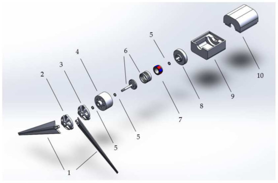
Figure 16.
Exploded view of the developed SWT.
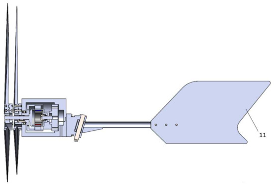
Figure 17.
Sectional view of the developed SWT.
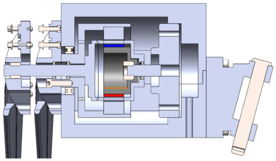
Figure 18.
Sectional view of the wind turbines gearbox.
Table 10.
Wind Turbine Parts.
4. Conclusions
The integrated design between CMGT and the SWT was developed as shown in this study. The magnetic-gear development steps started with the initialization of the design components and parameters, then by analyzing the flux density calculation using an equivalent magnetic circuit (EMC), determining the geometry parameters, and finally selecting the design parameters and designing the integrated design of CMGT and the turbines.
The developed magnetic gear performs with promising simulation results, with an output transmitted torque in the inner rotor (output) of 8.7 Nm, 56.9 Nm in the outer rotor, and 48.0 Nm in the pole-piece. This means this mechanism can produce a higher transmitted torque compared to the bevel-geared wind turbine. The speed characteristics are also compromised to increase the rotational speed of the generator to produce more electricity. The flux densities in the air-gaps are 1.0200 and 0.8314, which lie in the outer and inner air-gap, respectively.
The following outcomes were also achieved by completing the research objectives, such as an EMC model used for the one-dimensional analysis of magnetic air-gap flux density, a technical specification of the final design, and a parametric three-dimension-modeled design integrated between the magnetic gear and the wind turbine.
Although many aspects have been investigated in this paper, there is plenty of scope for investigating future relevant work. Due to the limitation of the EMC that has been modeled, which caused a higher error, a two-dimensional EMC can be modeled in magnetic gear topology. The model will also be better if the final function is the transmitted torque, and not only the magnetic flux.
The developed magnetic gear design is integrated with the wind turbine, which was selected randomly. More consideration of the magnetic gear characteristics will improve the optimum results of the design parameters, i.e., gear ratio consideration by changing the pole configurations, torque ripple reduction, and efficiency, so that there will be more than one design to compare with each other.
Further investigation into these research results could include computational analysis for the final design. Stress–strain study in the magnetic gear or even in the wind turbine blades, hubs, nacelle, and furling mechanism would be interesting. Other than that, the depiction of the wind flow analysis or computational fluid dynamics would also be challenging. When the final design and analysis have been completed, manufacturing the model, experimenting with the prototype, and field testing constitute a remarkable opportunity to improve the research data.
Author Contributions
Conceptualization, Y.-C.W. and M.-C.T.; formal analysis, S.N.F.; investigation, F.-M.O. and S.N.F.; methodology, F.-M.O. and S.N.F.; resources, M.-C.T. and F.-M.O.; software, S.N.F.; validation, Y.-C.W. and F.-M.O.; supervision, Y.-C.W. and M.-C.T.; writing—original draft, S.N.F.; writing—review and editing, Y.-C.W. All authors have read and agreed to the published version of the manuscript.
Funding
This research was funded by Ministry of Science and Technology, Taiwan, R. O. C. under Grant numbers MOST 109-2622-8-006-005 and MOST 110-2221-E-224-023-MY3.
Institutional Review Board Statement
Not applicable.
Informed Consent Statement
Not applicable.
Data Availability Statement
Not applicable.
Acknowledgments
The authors would like to thank Ministry of Science and Technology, Taiwan, R. O. C. for granting us the permission to conduct the study (MOST 109-2622-8-006-005 and MOST 110-2221-E-224-023-MY3).
Conflicts of Interest
The authors declared no potential conflict of interest with respect to the research, authorship, and/or publication of this article.
References
- Adomavicius, V.; Watkowski, T.; Zilinskas, E.; Adomavičius, A. A Comparison of small scale wind turbines’properties. In Proceedings of the International Conference “Electrical and Control Technologies”, Kaunas, Lithuania, 7–8 May 2009. [Google Scholar]
- Chen, Y.B.; Wang, Z.K.; Tsai, G.C. Two-way fluid-structure interaction simulation of a micro horizontal axis wind turbine. IJETI 2015, 5, 33–44. [Google Scholar]
- Asfar, K.R. Adjustable Dual Rotor Wind Turbine. Patent US10385828B2, US, 20 August 2019. [Google Scholar]
- Wacinski, A. Drive Device for A Windmill Provided with Two Counter-Rotating Screws. Patent US7384239B2, US, 10 June 2008. [Google Scholar]
- Saulescu, R.; Jaliu, C.; Munteanu, O.; Climescu, O. Planetary Gear for Counter-Rotating Wind Turbines. Appl. Mech. Mater. 2014, 658, 135–140. [Google Scholar] [CrossRef]
- Tong, W. Wind Power Generation and Wind Turbine Design; WIT Press: Billerica, MA, USA, 2010. [Google Scholar]
- Blaabjerk, F.; Lonel, D.M. Renewable Energy Devices and Systems with Simulations in MATLAB and ANSYS; CRC Press: Boca Raton, FL, USA, 2017. [Google Scholar]
- Atallah, K.; Howe, D. A Novel High-Performance Magnetic Gear. IEEE Trans. Magn. 2001, 37, 2844–2846. [Google Scholar] [CrossRef] [Green Version]
- Wu, Y.C.; Chan, C.T. Development of magnetic gear mechanisms. Trans. Can. Soc. Mech. Eng. 2017, 41, 758–770. [Google Scholar] [CrossRef]
- Jing, L.; Chen, J.; Huang, Z. Analysis of magnetic field of magnetic gear during overload. In Proceedings of the 4th International Conference on Intelligent Green Building and Smart Grid (IGBSG), Yichang, China, 6–9 September 2019. [Google Scholar]
- Li, Z.; Liu, L. Dynamics analysis and electromagnetic characteristics calculation of permanent magnet 3-degree-of-freedom motor. Sci Prog. 2020, 103. [Google Scholar] [CrossRef] [PubMed]
- Wu, Y.C.; Tsai, M.C.; Chan, C.T. Creative mechanism design of magnetic gears integrated with continuously variable transmissions. Adv. Mech. Eng. 2018, 10, 1–8. [Google Scholar] [CrossRef]
- Zhao, H.; Liu, C.; Song, Z.; Yu, J. A fast optimization scheme of coaxial magnetic gears based on exact analytical model considering magnetic saturation. IEEE Trans. Ind. Appl. 2020, 57, 437–447. [Google Scholar] [CrossRef]
- Shah, L.; Cruden, A.; Williams, B.W. A variable speed magnetic gear box using contra-rotating input shafts. IEEE Trans. Mag. 2011, 47, 431–438. [Google Scholar] [CrossRef]
- Johnson, M.; Gardner, M.C.; Toliyat, H.A. A parameterized linear magnetic equivalent circuit for analysis and design of radial flux magnetic gears-Part I: Implementation. IEEE Trans. Energy Convern. 2018, 33, 784–791. [Google Scholar] [CrossRef]
- Ilmunandar, A.M.; Bramantya, M.A. Experimental study of counter-rotating wind turbine (full-scale, R = 1.5 m) with single generator using gearbox. IJSTR 2019, 8, 346–351. [Google Scholar]
- Thyroff, D.; Meier, S.; Hanh, I. Modeling integrated magnetic gears using a magnetic equivalent circuit. In Proceedings of the 41st Annual Conference IEEE Ind Electron Soc (IECON), Yokohama, Japan, 9–12 November 2015. [Google Scholar]
- Ubadigha, C.U.; Tsai, M.C.; Hsieh, M.F. Modulating ring structural configuration influence on the dual air-gap magnetic gear electric machine. IEEE Trans. Mag. 2017, 53, 8207406. [Google Scholar] [CrossRef]
- Hanselman, D.C. Brushless Permanent Magnet Motor Design; The Writer’s Collective: Cranston, RI, USA, 2003. [Google Scholar]
- Si, M.; Yang, X.; Zhao, S.; Si, J. Development of the equivalent magnetic circuit model for a surface-interior permanent magnet synchronous motor. In Proceedings of the 6th International Conference on Power Electronics Systems and Applications (PESA), Hong Kong, 15–17 December 2015. [Google Scholar]
- Hendershot, J.R.; Miller, T.J.E. Design of Brushless Permanent-Magnet Motors; Clarendon Press: Oxford, UK, 1994. [Google Scholar]
- Wu, Y.C.; Tsai, M.C.; Fajri, S.N.; Ou, F.M. Design of coaxial magnetic gear mechanisms using Taguchi method. In Proceedings of the 3rd IEEE International Conference on Knowledge Innovation and Invention (ICKII), Kaohsiung, Taiwan, 21–23 August 2020. [Google Scholar]
Publisher’s Note: MDPI stays neutral with regard to jurisdictional claims in published maps and institutional affiliations. |
© 2022 by the authors. Licensee MDPI, Basel, Switzerland. This article is an open access article distributed under the terms and conditions of the Creative Commons Attribution (CC BY) license (https://creativecommons.org/licenses/by/4.0/).