Article

Analysis of the Refraction Effect in Ultrasound Breast Tomography

by
Krzysztof J. Opieliński
1,*,
Mariusz Bułkowski
2,
Andrzej Gabryel
3 and
Andrzej Wiktorowicz
2
1
Department of Acoustics, Multimedia and Signal Processing, Faculty of Electronics, Photonics and Microsystems, Wroclaw University of Sciences and Technology, Wyb. Wyspianskiego 27, 50-370 Wroclaw, Poland
2
DRAMIŃSKI S.A., Owocowa 17, 10-860 Olsztyn, Poland
3
Olsztyn Cancer Center “Kopernik”, Kopernika 30, 10-513 Olsztyn, Poland
*
Author to whom correspondence should be addressed.
Appl. Sci. 2022, 12(7), 3578; https://doi.org/10.3390/app12073578
Submission received: 30 January 2022 / Revised: 20 March 2022 / Accepted: 30 March 2022 / Published: 31 March 2022
(This article belongs to the Special Issue Ultrasound Technology in Industry and Medicine)

Abstract

:

Featured Application

Research was used in the construction of a hybrid ultrasound tomography breast scanner developed by the DRAMIŃSKI S.A. company. The device has been designed as a new tool that allows the improvement of existing radiological methods for the early detection of breast cancer and is currently being tested in vivo during the implementation process.

Abstract

Ultrasound breast tomography (UBT) is a promising quantitative imaging method. It allows for precise analysis of ultrasound velocity distribution, which is related to tissue density and elasticity, enabling cancer detection. Only a few centers around the world have a prototype of the device for in vivo breast ultrasound tomography imaging. The quality of images reconstructed from measurements of ultrasound pulse transit times is adversely affected by the refraction of beam rays on the breast immersed in water. Refraction can be reduced using waveform tomography, ray-tracing, and ray-linking methods. However, this requires the acquisition of a pre-reconstructed pattern and is limited by extreme computational costs. In this study, the effect of refraction on transit time measurements of ultrasound passing through the female breast was analyzed under immersion conditions in water. It was found that the refraction causes the highest measurement errors in the area of the water/breast interface, and these can be reduced by adjusting the water temperature and changing the breast geometry. The results allow us to improve the quality of breast images reconstructed using an efficient transformation algorithm that assumes rectilinear ultrasound propagation paths between transmitters and receivers. In vivo breast studies were performed on the developed hybrid UBT scanner.

1. Introduction

There is no doubt that widespread and effective women’s diagnostics regarding the risk of breast cancer is a major worldwide problem [1,2].
Imaging of breast lesions is currently the primary method for their detection and initial clinical suspicion of malignancy [3]. Histopathological examination of the material obtained by biopsy is performed to confirm suspicion of a malignancy of breast cancer diagnosed by imaging. The most common diagnostic imaging examinations for early detection of breast cancer are X-ray mammography (MMG) and B-mode conventional ultrasound (USI). In older women, a higher detection rate is observed with MMG, which, in addition to the risks associated with X-ray exposure [4], can be painful due to the need for mechanical compression of the breast [5]. Mammography of dense breasts (mainly in young women) and implant-informed breasts is not reliable due to frequent false negative results [6,7,8], which significantly cause delay in cancer diagnosis. Furthermore, mammography results are affected by premenopausal or postmenopausal status and the use of hormone replacement therapy [9]. There is also a potential risk of cumulative effects of ionizing radiation. The risk of cancer increases by approximately 1% per five mammography tests, so physicians do not recommend mammography screening more often than every 2 to 3 years or in women under 40 years of age. Mammographic screening also has limitations, such as overdiagnosis and overtreatment [10]. 2D mammography, despite being the only screening method, is being phased out in many countries (e.g., Switzerland) due to its low effectiveness [11]. Recently, a new mammographic test has been introduced, called 3D mammography (tomosynthesis). The test shows higher sensitivity compared to traditional mammography (2D). However, the method is very similar because it is based on X-rays and therefore has the same contraindications. Extending mammographic screening to include additional conventional ultrasound imaging, especially in dense breast tissue, significantly increases the chance of early cancer detection [12,13]. The high sensitivity of USI [14] is, in turn, limited by its low specificity [15]. This causes false positive results, increasing the number of unnecessary biopsies [6]. Furthermore, results of studies presented in the literature suggest that it is difficult to precisely distinguish ultrasound-guided isoechogenic lesions in the surrounding fat. These disadvantages of MMG and USI mean that, despite regular screening, breast cancer is often not diagnosed in its early stages. Magnetic resonance imaging (MRI) has become the preferred method of breast examination for women at high risk of developing cancer. The use of this method in the detection of breast cancer is significant due to its high sensitivity and moderate specificity for tumor masses larger than 5 mm, including ductal carcinoma in situ (DCIS) [16]. With the ability to analyze breast morphology, magnetic resonance imaging provides qualitative and quantitative data on tumor vascularization, allowing differentiation of benign from malignant masses. However, magnetic resonance tomography scanners are very expensive due to the price of the equipment itself, the need to maintain it in special rooms, and the maintenance and hiring of qualified staff. In addition, intravenous administration of contrast agents can be required, which may enter the extravascular space or cause allergic reactions. The administration of contrast agents is limited in patients with kidney or liver disease. These disadvantages, as well as the cost of MRIs, limit the use of this method in the diagnosis of the female breast and make public MRI screening unattainable to date.
As we can see, there is currently no ideal diagnostic method that can be recommended to any woman for breast examination. The market for diagnostic breast imaging devices is not sufficiently saturated due to the imperfections of each of the available methods. A novel hybrid method that can overcome most of the disadvantages of MMG, USI, and MRI is ultrasound breast tomography (UBT). Recently, several research centers around the world performed work to build a prototype of the ultrasound computer tomography device for a breast screening imaging tool in women (with the ability to scan, measure, acquire data, and reconstruct and process images in vivo) [17,18,19,20,21]. The design, operation and imaging methods of each device are specific and varied. One of the few advanced prototypes of in vivo hybrid ultrasound breast tomography scanners was developed in Poland by DRAMIŃSKI S.A. company [20,21]. The device uses transmission ultrasound tomography (UTT) and reflection ultrasound tomography (URT) modalities [22] to image female breast tissue, as well as the omnidirectional (full-angle) spatial compound ultrasound imaging modality (FASCI) by assembling multiple ultrasound images acquired at angles selected from 0 to 360° [23], analogous to the so-called compound imaging (CI) method. The FASCI modality is used as a complement to the UTT and URT modalities. This approach enables the acquisition of comprehensive diagnostic information on the tissues under study. It should be noted that physicians are extremely interested in the additional B-mode echographic breast imaging modality implemented in the ultrasound tomography scanner as a well-known standard for medical diagnosis. The device, which combines several ultrasound technologies, is universal (no age limits) and neutral for health (no ionizing radiation or contrast agents). The use of a UBT scanner in breast screening is expected to create a new world standard in breast disease diagnostics.
The quality of quantitative images obtained as a result of the reconstruction process from the measurement of the transmission transit time of ultrasound wave pulses with the use of the hybrid UBT scanner is adversely affected by the phenomenon of beam refraction at the water and submerged breast border (also in inhomogeneities in the breast structure [24]). The influence of this phenomenon can be considered and significantly reduced using waveform tomography, ray-based inversion, ray-tracing, and ray-linking methods [25,26,27,28,29,30,31,32,33,34,35]. However, this requires the acquisition of a preconstructed pattern and is limited by extreme computational costs, despite the possibility of using various simplifications and regularizations, as well as by the need to acquire, store, and process a huge amount of measurement data. These methods essentially undermine breast imaging during or immediately after in vivo scanning, significantly increasing the cost of manufacturing the UBT scanner.
In the present study, research was conducted to minimize the effect of the phenomenon of refraction on quantitative ultrasound tomography imaging of breast structure in a manner that does not require complex computational techniques or waveform or inversion image reconstruction methods [32,33,34,35]. To this end, the effect of refraction on transmission tomography measurements of the transit time of an ultrasound wave through female breast tissue under immersion conditions in water was analyzed. It was found that refraction introduces the largest measurement errors in the area of the water/breast interface and can be reduced by the appropriate choice of water temperature and changing the breast geometry. In vivo test breast examinations were performed on the owned prototype hybrid ultrasound tomography scanner. The results obtained allowed us to improve the quality of reconstructed breast images using an efficient transformation algorithm that assumes straight-line ultrasound propagation paths between transmitters and receivers [22], without the need for special hardware in the form of expensive and energy-intensive GPU graphics cards [30].

2. Materials and Methods

The refraction phenomenon occurs when an ultrasound wave falls on the border of two media with different ultrasound propagation velocities at an angle different from normal (oblique incidence). Then the direction of the wave changes, it is refracted at a certain angle. The angle of incidence and angle of refraction obey the well-known Snellius law, as in optics.

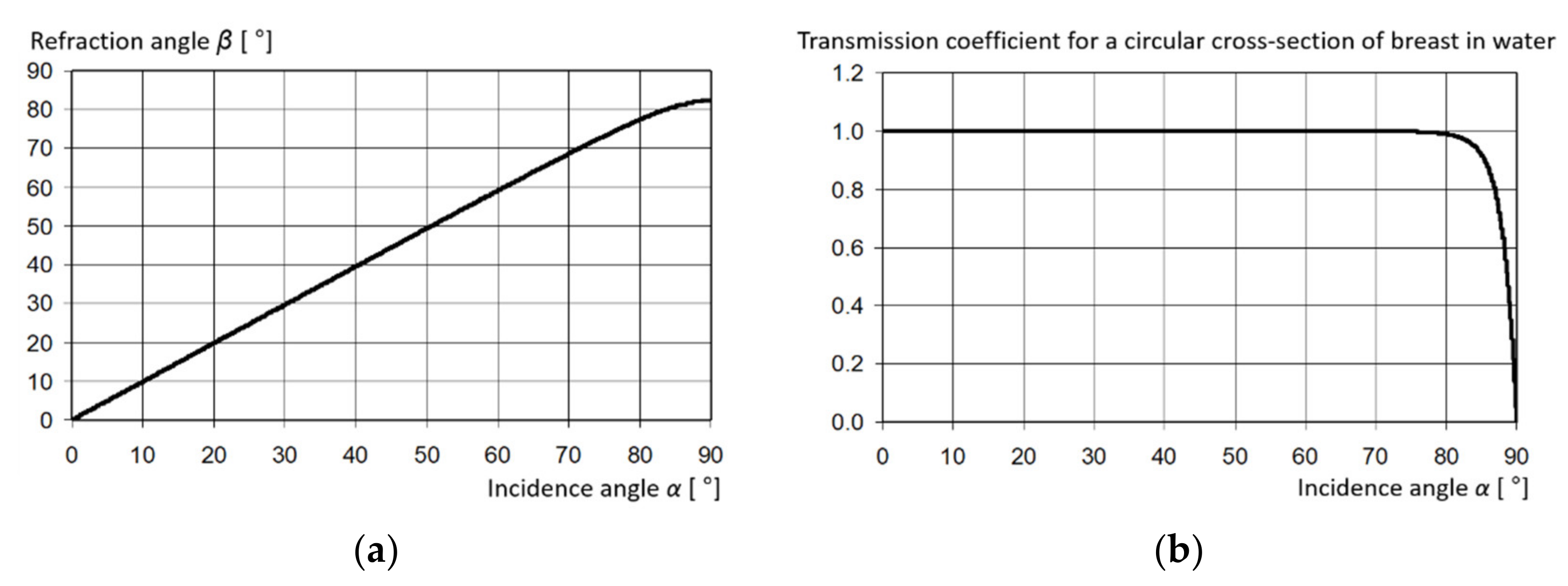
2.1. Refraction in Transmission Method

In the case of transmission of ultrasound waves through the soft tissue structure of a female breast immersed in water, the refraction phenomenon will occur due to the differential velocity of ultrasound in water and the breast and due to the inhomogeneity of the breast structure. It can be estimated that the refraction of the ultrasound beam at the water/breast interface will not be significant due to the near unity index of refraction n, defined as the ratio of ultrasound velocity in water to ultrasound velocity in the structure [22]. Figure 1a shows the dependence of the refraction angle of the ultrasonic wave at the straight-line interface of the water/breast on the angle of incidence, calculated from the Snellius law. Figure 1b shows the dependence of the amplitude pressure coefficient of the transmission of the ultrasonic wave through a circular breast section immersed in water, calculated sequentially for the water/breast/water boundaries using the formula:
D p = cos α ρ 1 c 1 ρ 2 c 2 1 c 2 c 1 2 sin 2 α cos α + ρ 1 c 1 ρ 2 c 2 1 c 2 c 1 2 sin 2 α  
where α—the angle of incidence of the ultrasound wave at the boundary of the first and second mediums, ρ1—the density of medium 1, c1—the ultrasound velocity in medium 1, ρ2—the density of the medium 2, c2—the ultrasound velocity in medium 2, Dp—the pressure coefficient of transmission of the ultrasonic wave through the boundary of the two media.
Calculations show that in almost the entire range of incidence angles, the refraction of ultrasound wave rays when passing through breast tissue in water is negligible, while the transmission coefficient is close to unity in the range of incidence angles 0–80° (Figure 1). Simulation of the phenomenon of ultrasound wave refraction by means of a mathematical model that takes into account the refraction and elongation of beam rays for a complicated internal structure of a heterogeneous biological medium is a difficult task due to the necessity of considering refraction coefficients for all borders between quasi-homogeneous structures and the necessity of an iterative search for such a beam ray coming from the source, which will reach the detector after multiple refractions in the medium (rays are curvilinear in the case of continuous changes of the ultrasound velocity in the structure) [36,37,38,39]. Moreover, there may be many such rays in the case of n > 1, so we should additionally look for a transition in the shortest time and with a measurable amplitude. Such an operation must be performed for each position of the sending and receiving pair of transducers when scanning a biological medium with the transmission method [22]. Problems of critical angles must still be considered; above such angles of incidence, the ultrasound wave disappears in the tissue.

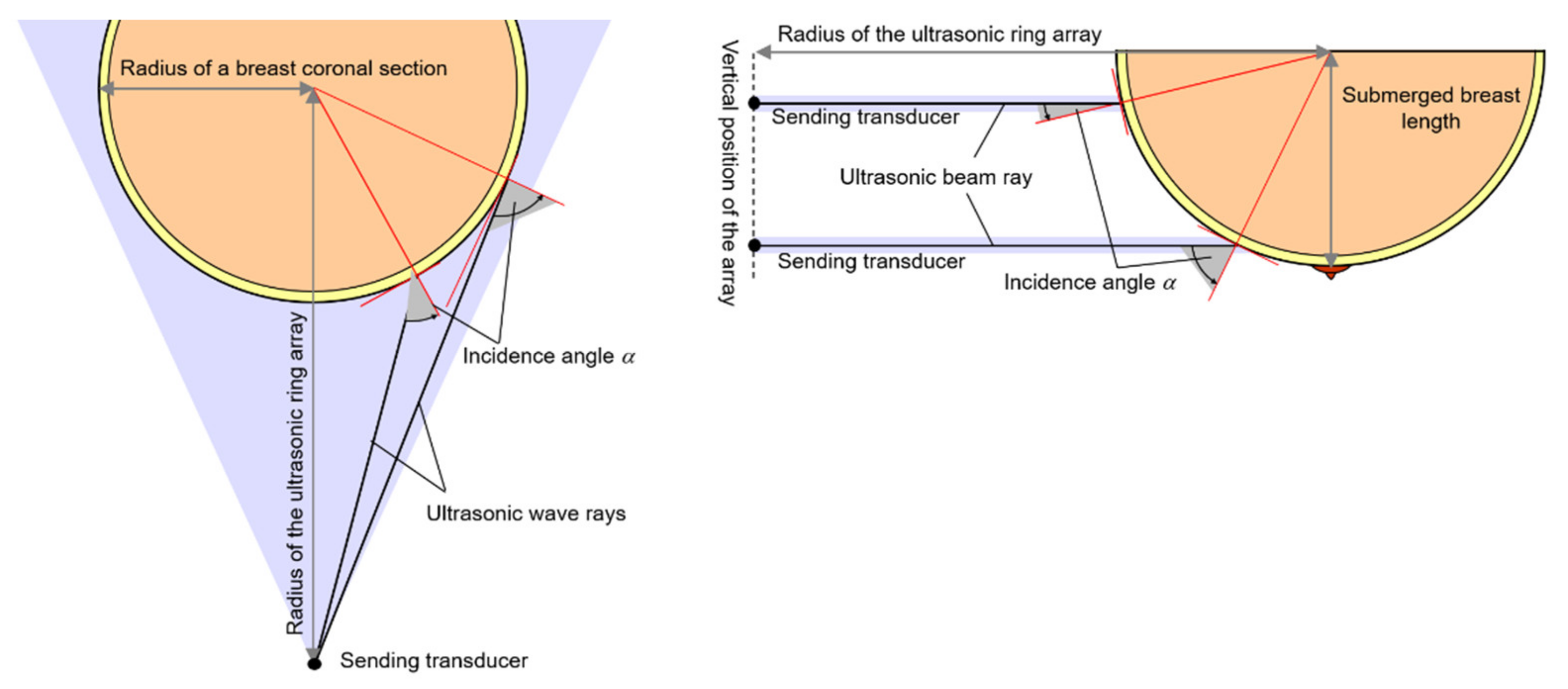
2.2. Refraction in Ultrasound Transmission Tomography Scanning

To illustrate refractive errors in the ultrasound transmission tomography scanning process of breast tissue, numerical calculations were performed for a homogeneous circular cylinder section simulating a coronal cross-section of a 150 mm diameter female breast with an assumed average ultrasound velocity for a premenopausal woman cbreast = 1510 m/s (T = 37 °C) [40,41], immersed in water at temperature T = 25 °C (cwater ≈ 1496.7 m/s) and T = 37 ° C (cwater ≈ 1523.7 m/s), respectively. The distance between the transmitter and the receiver in water was set as lo = 300 mm.
The calculations assumed point sizes for each pair of ultrasonic transmitter and receiver. The method for determining the path of the beam rays from the transmitter to the receiver was based on an iterative search for the ultrasonic beam ray to reach the receiver fastest after bilateral refraction on a circular object of assumed ultrasound speed, immersed in water [22,24,42]. On the basis of the ray paths determined, the average values (projections) of the transit time were calculated, by which the distance lo was divided, obtaining the ultrasound velocity projections in the parallel ray geometry, when the pair of transmitting and receiving transducers was moved stepwise along the cross-section of the cylinder. Paths of the refracted rays were determined with high accuracy using the equations of the circle and the equations of the rotated straight and tangential lines in the geometry resulting from the adopted scanning system. In this way, the spread (n = 0.991) and focusing (n = 1.009) of the transmitted ultrasound wave beam can be simulated in the breast cross-section with an index of refraction close to unity, respectively. For both cases, the ray paths of refracted wave beams and calculated ultrasound velocity projection values for the cylindrical cross-section with and without refraction are presented in Figure 2 and Figure 3, respectively, in the parallel beam scanning geometry. Similar phenomena can be expected to occur at the soft tissue boundaries. For n < 1, there is always a wave transition from transmitter to receiver, and the blue areas in Figure 2 and Figure 3 indicate the scanning range for which the transit time along refracted rays is less than that along straight lines through water. For transmission measurements, this means that a pulse (of small amplitude) will appear in this area before the pulse passes directly through the water because of refraction on the circular cross-section of the cylinder. Depending on the rise amplitude of this pulse, the signal-to-noise ratio, and the detection threshold of the transit time measurement method, it may or may not be subject to detection. The imaging error of the object and its size may therefore vary, causing an enlargement of the cylinder cross-section and/or a misrepresentation of the ultrasound velocity near its boundaries. For n > 1, there is always an area where transmission of the ultrasonic wave cannot be achieved along the path from the transmitter to the receiver. In Figure 2 and Figure 3, this area is marked with red; blue is used to mark the area where the ultrasound wave is simultaneously transmitted along two different refracted rays, while the rays marked with black reach the path from the transmitter to the receiver the fastest and due to the smaller refraction angle, the pulse amplitude in this case is larger. Therefore, it can be assumed that the duplicated rays will not affect the measurement of the pulse transit time of the ultrasonic wave. As can be seen in Figure 2 and Figure 3, the refraction phenomenon of ultrasound wave rays after passing through the cylinder cross-section is clearly visible, first of all, at its edges.
In both cases, there are areas near the edges of the cross-section that will not be penetrated by the ultrasonic wave due to the refraction phenomenon, and these areas have a larger size for n > 1 than for n < 1 for the same absolute value of the difference |n−1|. In the case of wave beam spreading (Figure 2a and Figure 3a), the area of overlap between the detection points of the rays passing after refraction through the cross-section of the cylinder and the rays passing directly through the water is only about 4.5 mm at its lateral edges (colored blue). It means that in transmission imaging, the diameter of the breast cross-section can be enlarged by a maximum of about 9 mm. In the case of wave focusing (Figure 2b and Figure 3b), the transmission fading area (colored red) is approximately 7.2 mm at both lateral edges of the cylinder. This measurement situation is very unfavorable. The random noise pulse time, the start time, or the end time of the measurement window will then be determined when measuring the pulse transit time within a certain time window. Such measurements will introduce errors, especially for ultrasound tomography image reconstruction [42,43]. In order to minimize signal fading errors (Figure 2b and Figure 3b), it is therefore necessary to develop algorithms that interpolate missing measurement values on the basis of neighboring values. For in vivo studies, it is also a good idea to set the temperature of water in which the breast is immersed in such a way that a refraction index close to unity can be obtained at the water/breast interface. Based on the results obtained from the calculations, it can be predicted that in the case of ultrasound transmission tomography measurements, the influence of refraction on the errors in the imaging of the structure of biological media is not significant for most soft tissues, which are characterized by the index of refraction 0.9 < n < 1.1. In the case of tissues, due to the refraction phenomenon, it is advantageous to use large lo distances between the source and the detector in relation to the size of the cross-section of the examined object. For large distances, when the axis of the pair of sending and receiving transducers is outside the object, a wave ray passing directly through the water instead of a ray refracted in the object can be expected to reach the receiving transducer. For small lo distances compared to the cross-sectional size of the object, the opposite situation is more likely, since transmission coefficients Dp(α) at the water/tissue interface for most soft tissues are close to unity over a wide angular range (Figure 1b). In such a situation, the size of the structure under study in the ultrasound tomography image can be artificially slightly enlarged. A small lo distance, on the other hand, is advantageous because of the improved resolution for detecting small changes in ultrasound velocity introduced by small inhomogeneities located in the path of the transmitted ultrasound wave. Experiments performed by the authors on tissue phantoms and biological media have shown that for n < 1 (the ultrasound velocity in the object is higher than in its surroundings), as a result of intense refraction of passing rays near the edge of the water/phantom, a narrow ring of significantly overstated ultrasound velocity values appears in the reconstructed cross-sectional image of the phantom around its edges. On the other hand, for the case n > 1 (the ultrasound velocity in the object is lower than in its surroundings), this ring is characterized by significantly understated ultrasound velocity values [42,43]. Figure 4 shows both artefacts in the example of a quantitative ultrasound velocity distribution image reconstruction in the cross-section of an ostrich egg measured with the prototype of the hybrid UBT scanner developed by DRAMIŃSKI S.A. Typical ultrasound velocity values for white (1521–1536 m/s) and yolk (1504–1510 m/s) found in eggs [44] can be read from the image. The distortions on ultrasound tomography images in the form of lines are mainly due to the disappearance of ultrasonic transmission pulses as a result of the disruption of the egg surface smoothness that occurs after cooking, on the side of the air chamber.

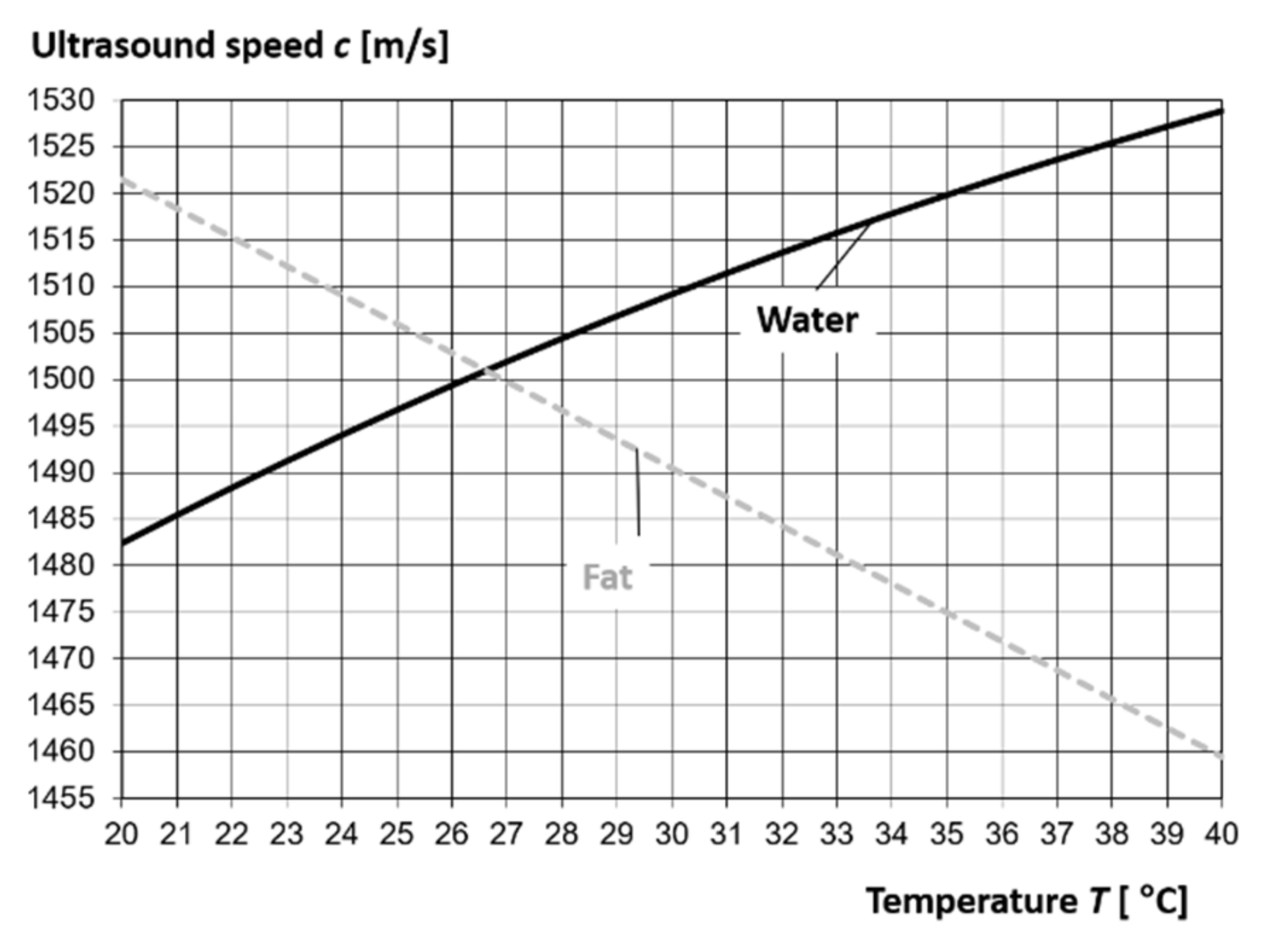
2.3. Acoustic Parameters of Water, Fat, and Glandular Tissue of the Breast

In Chapter 2.2, breast tissue was considered homogeneous. In reality, there is a fat layer under the breast skin where the ultrasound velocity is much lower than the average velocity in the glandular tissue. Thus, Figure 5 illustratively analyzes three scenarios for the passage of four ultrasound beam rays in divergent scanning geometry from the transmitter to four different receivers of a multi-element ultrasonic ring array through a breast (with a subcutaneous fat layer, and without considering the thin skin layer at this stage) submerged in water. These are illustrative drawings obtained using the computational model described in Chapter 3.1. All three scenarios assume passage of the rays at angles of 0°, 15°, 45°, and 52°, respectively, to the beam propagation direction.
The first and second ray pass successively through the water/fat/glandular tissue/fat/water layers. The angle of the third ray was chosen so that, in the absence of refraction, it passes through the water/fat/water layers just at the edge of the glandular tissue. The fourth and final ray from the right side of the beam passes through water only, just at the edge of the breast fat tissue. The three scenarios illustrate the refraction pattern of the ultrasound beam rays (black lines) for 3 different cases defining the mutual relationships of ultrasound velocities in water (1), fat (2), and glandular breast tissue (3), respectively: c1 < c2 < c3; c1 = c2 < c3; c1 > c2 and c2 < c3, with only the adjusted velocity value c1 in water (changing its temperature). The white lines illustrate the ray trajectories after the transition without taking refraction into account. As can be seen, the subcutaneous fat layer can lead to a significant deviation of the ultrasonic beam path from a rectilinear transition due to the refraction phenomenon. Thus, this chapter analyzes the acoustic parameters of water, fat, and glandular breast tissue, which can affect the refraction phenomenon of ultrasonic beam rays as well as the acoustic parameters of the skin, a thin layer of which is above the fat layer.
The most important acoustic parameter affecting the refraction of ultrasound wave beam rays is its propagation velocity in the medium, especially its changes as a result of inhomogeneity or layering of the tested medium. The weakening of the energy of the ultrasound wave after its passage through the medium is also important, as it depends mainly on the ultrasound attenuation coefficient and the wave transmission coefficient (Figure 1b) through the layers of different acoustic impedances (the product of the ultrasound velocity and the density of the medium). The ultrasound velocity is temperature dependent and increases with increasing temperature in most soft tissues and in water. In fat, the ultrasound velocity decreases with increasing temperature. The average value of the propagation velocity of the longitudinal ultrasound wave in soft tissues is assumed to be c = 1540 m/s (density ρ = 1058 kg/m3, acoustic impedance Z = 1.62∙106 kg/(m2∙s)), and the mean value of the attenuation coefficient of the amplitude of the ultrasound wave is α = 0.5 (dB/cm)/MHz ≈ 5.8 (Np/m)/MHz [40]. With some approximation, it can be assumed that in the frequency range of 1–6 MHz, the ultrasound attenuation coefficient α/f in soft tissues is constant. Increasing the water or fat content in the tissue generally decreases the ultrasound velocity value. For soft tissues not containing fat, the average values of acoustic parameters are respectively: c = 1575 m/s, α = 0.3 (dB/cm)/MHz ≈ 3.5 (Np/m)/MHz, while for tissues containing fat: c = 1465 m/s, α = 0.6 (dB/cm)/MHz ≈ 6.9 (Np/m)/MHz [45]. The ultrasound velocity in water is, respectively: 1496.7 m/s for 25 °C, 1509.2 m/s for 30 °C, and 1522.9 m/s for 36.6 °C [40]. Based on data from the literature, ultrasound velocity in breast adipose tissue (fat layer under the skin) is 1470 m/s in vivo (at body temperature T = 36.6 °C). The temperature coefficient of breast fat in the temperature range 22–37 °C is dc/dT = −3.1 (m/s)/°C. The temperature dependence of the ultrasound velocity in water and fat is illustrated as a graph in Figure 6.
According to data from the literature [40,41], the average ultrasound velocity in glandular breast tissue of a premenopausal woman in vivo is in the range 1450–1570 m/s, with 1510 m/s being the average value. The thickness of the breast skin is in the range of approximately 0.5–2.5 mm [46]. The average velocity of ultrasound in the skin is 1642 m/s [47]. The ultrasound attenuation coefficient α in water is small, so it is defined in (dB/m), unlike in tissues where it is in dB/cm [40]. At 2 MHz, the attenuation coefficient of ultrasound in water is, respectively: 0.87 dB/m for 20 °C, 0.76 dB/m for 25 °C, 0.66 dB/m for 30 °C, and 0.57 dB/m for 36.6 °C. Thus, it can be concluded that the attenuation of ultrasound in water is negligibly small compared to that in tissue. Attenuation in fat at body temperature is about 1.2 dB/cm for 2 MHz (increases approximately linearly with frequency). The attenuation coefficient of the ultrasonic wave in breast tissue for frequencies of 0.5–6 MHz in the temperature range of 25–37 °C is, on average, α = (0.75 ± 0.3)·f1.5 dB/cm, i.e., 2.12 ± 0.85 dB/cm for 2 MHz [40]. Decreasing the temperature increases the attenuation, but the changes are not large. The attenuation of ultrasound in the skin of the breast is, on average, α = 2.4·f0.6 dB/cm [40].

2.4. Method and Measuring System

To verify the results of the calculation obtained, in vivo patient tests were performed using a prototype of the hybrid UBT scanner developed by the Polish company DRAMIŃSKI S.A., for the temperature of the water surrounding the breast immersed in the tank, T = 20 °C, 25 °C, 30 °C, respectively. The water was not heated to body temperature (36.6 °C) due to the non-standard value, not currently foreseen for use in the scanner. It should be noted that the temperature 20 °C is a bit too low and patients often indicate discomfort with submerging and holding the breast in the tank for several minutes.
The view of a prototype of the hybrid UBT scanner developed by DRAMIŃSKI S.A. is shown in Figure 7.
The woman lies on the examination bed in a prone position with the breast submerged through the opening into a reservoir of distilled water heated to a fixed temperature. Examination of the selected breast is performed automatically by scanning coronal cross-sections in 1- or 2-mm increments using a vertically moving, multi-element ring array of ultrasonic transducers. The water in the reservoir provides adequate acoustic coupling between the transducers and the breast. The ring array is connected to a mechanical system that positions it at the appropriate depth (on the Z-axis) and is responsible for its movement on this axis. The array consists of 1024 miniature piezoceramic transducers evenly distributed on the inner side of a ring of diameter Dr = 260 mm surrounding the breast. The elementary transducers have active area dimensions of 0.5 mm × 18 mm and operate at approximately 2 MHz central resonant frequency. The newest model of the ring array is characterized by a wide band of ultrasonic transducers, B = 1.5 MHz, due to the well-optimized front matching layer. Each transducer can act as a sending and receiving element. Measurement data acquisition methods are presented in [20,21]. Depending on the length of the breast, approximately 100–200 coronal cross-sections from the base to the nipple are examined. Data acquisition in the transmission modality currently takes 3 s per coronal breast cross-section. In the next version of the prototype, this time will be reduced to about 2 s. Note that the primary limitation here is the transit time of the beam from the sending transducer to the receiving one. Small movements of the patient are not a problem; at most they cause small shifts between individual coronal sections in the 3D image, which can be corrected automatically.
For the reconstruction of quantitative transmission images of ultrasound velocity distribution (UTTc) on ultrasound tomography scanner, the transform-based filtered back projection method (FBP) [45], appropriately adapted to introduce projection sets of ultrasound propagation velocity and attenuation values, was used. From individual 2D images (so-called slices), 2D images in orthogonal cross-sections MPR (Multiplanar Reconstruction) [48], and 3D images using the MIP (Maximum Intensity Projection) tomographic technique [49] were also reconstructed.

3. Results

Based on the preliminary studies presented earlier, it was concluded that regulation of the temperature of the water in which the breast is immersed during ultrasound tomography examinations may allow the refraction angles of ultrasound wave beam rays to be reduced at the water/skin/fat/breast/fat/skin/water boundaries. This can lead to reduced distortion of reconstructed breast cross-sectional images, as a result. Therefore, in this chapter, a detailed analysis of the variation of water temperature in ultrasound tomography imaging is performed on the basis of appropriate calculations and measurements.

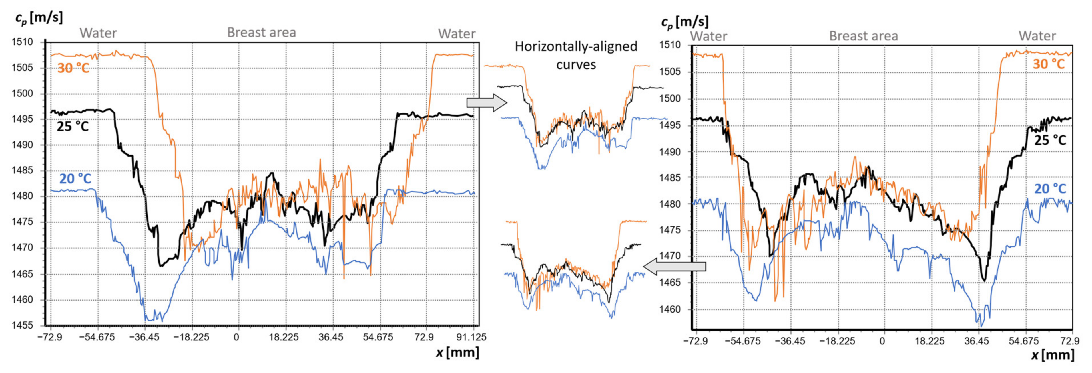
3.1. Analysis of the Effect of Water Temperature on the Refraction of the Beam Path

To analyze the influence of the water temperature in the UBT scanner tank on the refraction phenomenon of the ultrasound wave that penetrates the cross-section of the breast immersed in this water, two different curvilinear layers of water/skin/breast fat/breast glandular tissue were created, shown in Figure 8.
The adoption of these two models is based on the assumption that shortly after the breast is immersed in vivo in water at a temperature different from the body temperature (36.6 °C), a value of about 36.6 °C is briefly still maintained in the subcutaneous fat layer, which is, on average, 5 mm thick. After keeping the breast submerged for a longer time, a temperature gradient should develop in the subcutaneous fat layer. This is assumed to be a linear gradient from the temperature value in the surrounding water to the value in the glandular tissue of the breast located at the fat layer. To simplify the calculations, the average, constant value of the ultrasound speed in the skin (1642 m/s) with assumed thickness of 2 mm was set. The fat layer was divided into five sublayers with linearly varying temperature (Figure 8). It has been verified that at this fat layer thickness, the inclusion of more sub-layers has no significant effect on the refraction phenomenon in the developed model. Calculations were performed for four different water temperatures: 20, 25, 30, 35 °C and both models—without and with gradient. Ultrasound velocity conditions in water for these temperatures were taken as: 1482.4 m/s, 1496.7 m/s, 1509.2 m/s, and 1519.8 m/s (Figure 6). The ultrasound velocity in the subcutaneous fat layer at body temperature was taken as 1470 m/s (Figure 6), and in the glandular tissue of the breast, as 1515 m/s, since most refractive errors in ultrasound transmission tomography images were observed for dense breasts. Ultrasound velocities in the gradient layers of breast adipose tissue were determined from the temperature coefficient (Figure 6) in the model. For example, for a water temperature of 25 °C, the temperatures in the five individual layers of adipose tissue are, respectively: 26.9, 28.9, 30.8, 32.7, and 34.7 °C and the corresponding ultrasound velocities in these layers: 1500, 1494, 1488, 1482, and 1476 m/s. The calculations were performed for beam rays that ranged from 5° to 37° (the angle from the Y-axis to the beam ray), which ranged from 7.2° to 60.4° after recalculation to incidence angles from water to the curvilinear skin surface. Furthermore, for each water temperature (20, 25, 30, 35 °C) and both models, calculations were also made for the maximum possible values of the beam ray angle, still allowing this ray to pass through all layers (water/skin/fat/breast/skin/water). These critical angles of beam rays are 62°, 63°, 64°, and 64.8°, respectively, after recalculation into incidence angles from water to the curvilinear skin surface, regardless of the model (Figure 9 and Figure 10). The angle of incidence αi is equal to or greater than the first critical angle determined by the following relation, and the longitudinal wave disappears in the medium i + 1:
sin α c r i t i c a l i = c L i c L i + 1   ,
(where c L i —ultrasound velocity in the medium i, c L i + 1 —ultrasound velocity in medium i + 1). The calculations in the developed model are realized by determining angles of incidence and refraction of the ultrasonic beam rays on the individual layer boundaries using a generalized formula:
sin α i c L i = sin β i + 1 c L i + 1
(where β i + 1 —refraction angle in the medium i + 1). These angles and paths of rays in individual layers are calculated from geometric relations taking into account intersections of straight lines with circles constituting borders of individual layers. The developed model is universal and allows adjusting any values of the parameters (diameter of the breast section, distance of the ultrasound source from the breast section, thickness and ultrasound velocities in the layers, water temperature).
The results of the calculation of the refraction of the incident ultrasonic wave beam ray from water on both layer models (Figure 8) are visualized in Figure 9 and Figure 10. The black diagonal dashed lines show the rectilinear course of ultrasonic beam rays passing through the breast without taking into account the refraction phenomenon at individual layer boundaries. The fragments of the outgoing ultrasonic rays, including refraction into the water after passing through the breast, are marked with a solid blue line. For incoming (black) and outgoing (blue) rays, the values of angles of deviation from the Y-axis are given. The short, dashed lines perpendicular to the curvilinear boundary of each layer illustrate the perpendiculars to the tangents at the intersections of the layer boundaries by the passing and refracted wave ray in succession. In this way, it is possible to visually assess the change in ray path due to passage through the layers compared to the rectilinear path (assumed in the image reconstruction) and the change in ray length in each layer for both models, different temperatures in the water, and different angles of incidence of the wave at the water/breast boundary.
The differences between the results obtained for the model without and with the fat gradient appear to be insignificant even for the incidence angles close to the critical ones (compare Figure 9 and Figure 10).
When analyzing individual cases for beam ray angles in the range of 5° to 37° shown in Figure 9 and Figure 10 (top rows), it can be observed that as the water temperature increases to 30 °C, the refraction phenomenon at individual layer boundaries proceeds with decreasing intensity. The minimization of refraction results in a correct (close to rectilinear) course of the ultrasonic wave beam ray through the layers. Furthermore, the refracted rays coming out of the breast section have larger Y-axis deviation angles compared to the incident rays. For a water temperature of 35 °C, the refraction phenomenon is still low, but the outgoing rays have smaller angles of deviation from the Y-axis compared to the incident rays. This means that in the angular range of 0–37° we can find the optimum value of the water temperature (between 30 °C and 35 °C) due to the refraction minimization. For beam ray angles close to the critical incidence angles at the breast cross-section boundary (see the second row in Figure 9 and Figure 10), the refraction phenomenon successively increases intensity with increasing water temperature from 20 °C to 35 °C. Moreover, in this case, the refraction angles especially at the water/skin and fat/skin boundaries increase significantly, and deviation of the ray path from straightness are large. This is also associated with an elongation of the transition paths through these layers, resulting in a weakening of the ultrasonic signal.
In order to optimize the value of the water temperature for minimizing the refraction phenomenon, the parameter ∆opt was chosen to characterize the difference in the angle of deviation from the Y-axis of the beam ray incident from the water to the breast border (skin layer) and the ray exiting the breast cross-section (skin layer) into the water:
Δ o p t = α I N α O U T   °
where α I N —angle of deviation from the Y-axis of the beam ray incident from the water on the boundary of the breast skin layer, α O U T —angle of deviation from the Y-axis of the beam ray exiting the breast skin layer into the water. The optimal value of ∆opt = 0 means that the beam ray incident from the water on the breast skin has the same directional coefficient as the beam ray that exits from this section into the water. Figure 11 shows the results of the calculation of the parameter ∆opt as a function of the angle α I N , for different values of the water temperature and both models (without and with a temperature gradient in the fat layer). On the auxiliary X-axis, the values of incidence angles of the beam rays at the water/skin boundary determined from α I N angles are given.
Due to the negligible differences in the refraction of the ultrasound beam rays in the cross-section of the breast with uniform and stratified fat (cf. Figure 9 and Figure 10), the differences are also small for the parameter ∆opt ( α I N ) (Figure 11). In the plot, the angle α I N ≈ 32° (corresponding to the angle of incidence at the water/skin boundary ~50°) is characteristic, for which the course of ∆opt ( α I N ) changes its character and starts to increase or decrease more intensively depending on the temperature. Then ∆opt starts to decrease from an angle α I N ≈ 35° (i.e., incidence angle of 55.9°) at each water temperature, until finally ∆opt decreases sharply for angles α I N > 37 ° (i.e., incidence angles larger than about 60°). Positive but close to zero values of ∆opt can be observed for α I N ≤ 35° for a water temperature of 30 °C. Figure 12 shows the results of the optimization of the water temperature obtained with the developed models for the parameter ∆opt.
The optimization was performed by selecting the water temperature values separately for each angle α I N   of the beam ray (blue line and scale of the main Y-axis), so that the coefficient ∆opt tends to zero (orange line and scale of the auxiliary Y-axis). The water temperature in the optimization procedure was adjusted with a resolution of 0.1° because it is difficult to stabilize it more precisely in the real measurement system. On the auxiliary X-axis, the values of the incidence angles of the beam rays at the water/skin boundary determined from the α I N angles are given. The optimal temperature value due to the minimization of the refraction phenomenon (∆opt ≈ 0) for the range of angles α I N = 0–32° is from 32.6 °C to 32.1 °C, respectively. Starting from an angle α I N ≈ 36° (i.e., the refraction angle of ~58.1°) the optimal temperature value rapidly decreases to a value of about 24–25 °C for an angle α I N ≈ 37.5° and then quickly rises to a temperature of about 42 °C near the critical angle, and ∆opt ≈ 0 achievement is impossible over this range. Optimization shows the existence of a characteristic region (refraction/distortion ring) that starts from the angle of incidence from water to the breast skin of ~50°, where the phenomenon of refraction of the ultrasound beam rays in the cross-section of the breast immersed in water starts to contribute more and more, and its intensity increases exponentially later.

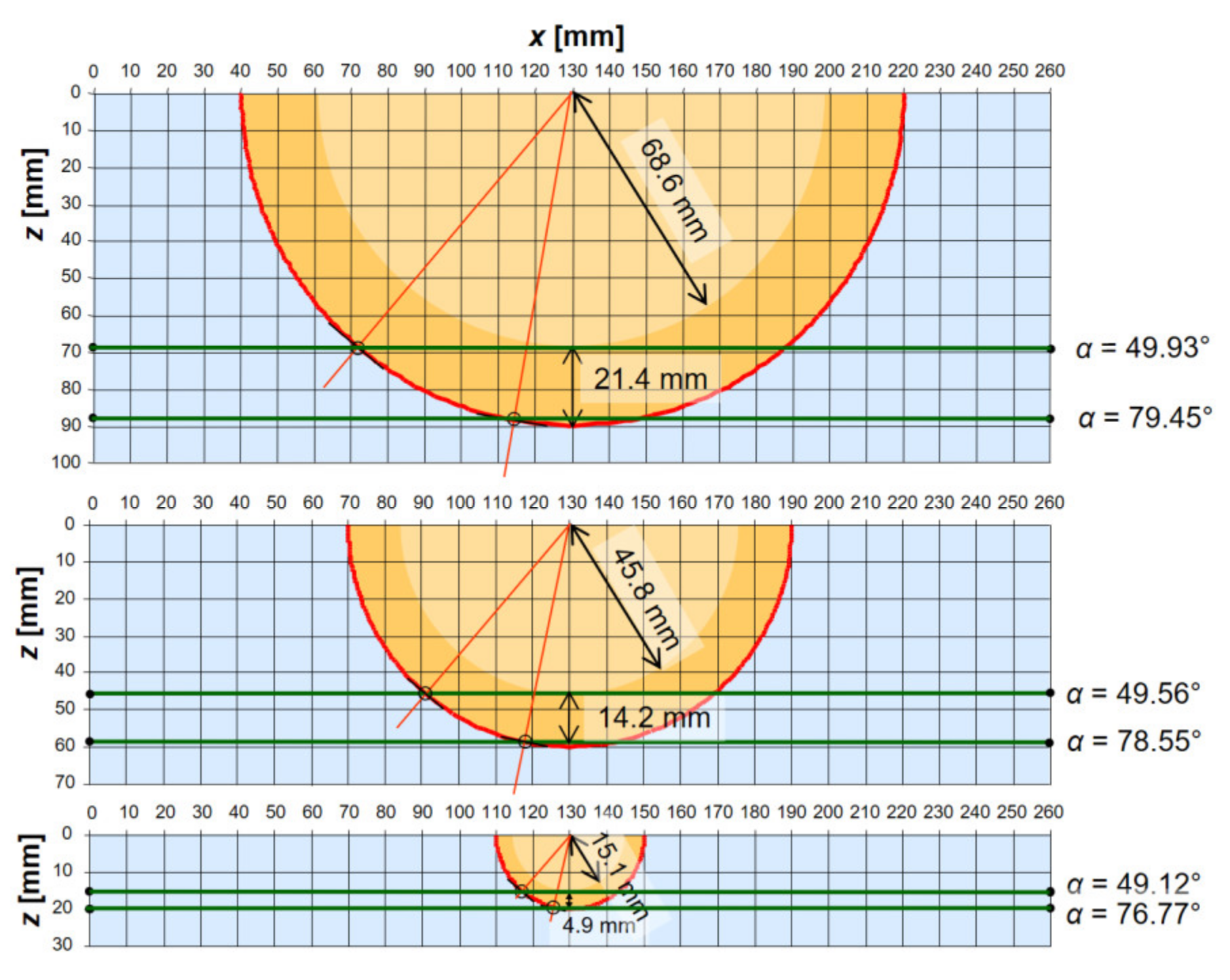
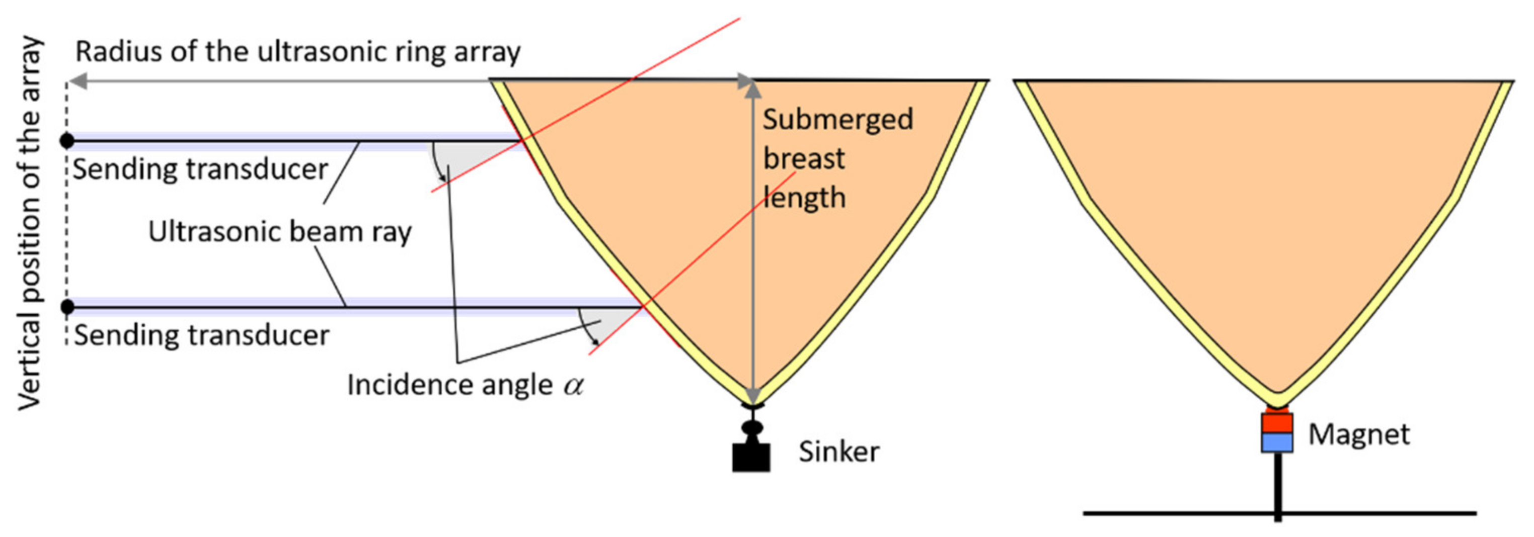
3.2. Analysis of Beam Ray Incident Angles on a Cross-Section of a Breast in Water

In the context of calculations and analyses performed in Chapter 3.1, it turns out that to be of interest to investigate the location and size of the area of the measured breast cross-section on which the ultrasonic wave beam rays coming out from the sending transducer of the ring array fall in water at specific angles (refraction/distortion ring). For this purpose, the simple geometric computational models shown in Figure 13 were developed.
This model is an extension of the model described in Chapter 3.1. It additionally allows the angular steps of the rays to be set with respect to the placement of 1024 ultrasonic transducers in the ring array of a prototype of the UBT scanner. The breast cross-section was modeled as a circle with a given diameter Db, without taking into account additional layers. This cross-section was assumed to be centrally located in the ultrasound tomography ring array composed of 1024 uniformly spaced ultrasonic transducers (angular pitch = 360°/1024 ≈ 0.3516°). The maximum diameter of the measurement area in water D p m a x when using 513 receiving transducers in one measurement projection is:
D p m a x = D r 2  
where Dr is the diameter of the inner ring of the ultrasonic array. Using the developed models, it is possible to visualize the area of the largest refraction of the ultrasound wave in the cross-section of a breast immersed in water, inside the ring array. The internal diameter of the ring array Dr = 260 mm was assumed in the modeling. The maximum diameter of the measurement area in water when using 513 receiver transducers in one projection is D p m a x = 183.85 mm, in this case. This number of receiving transducers is matched to their horizontal directivity characteristics in a ring array arrangement.
However, it should be noted that the reciprocal relationship between the inside diameter of the ring array and the diameter of the breast cross-section and the number of ultrasonic transducers are important in modeling. The angles of incidence of ultrasound beam rays in the cross-sectional area of the breast in the horizontal plane can approach 90° for the divergence angles of the beam that cover this cross-section (Figure 13), and the divergence angles decrease with the Db/Dr ratio. In the vertical plane, because the beam is narrow and the array moves along the breast hanging in water, the planes of the breast sections examined are parallel to each other and critical incidence angles above 60–70° are obtained only for sections of the breast tip, near the nipple (Figure 13). However, the phenomenon of vertical ray refraction (even small) is much more dangerous than horizontally, because in this case the rays of a narrow beam, after refraction, may not reach the surface of the receiving transducer on the other side. Thus, it may be impossible to examine the breast tip over a fairly large range of cross-sections because of vertical refraction.
The results of the model calculations of the area of the largest refraction of the ultrasound wave in the cross-section of a breast immersed in water, inside the ring array for three different diameters of these breast cross-sections (Db = 180, 120, 40 mm) are presented in the horizontal plane in Figure 14 and in the vertical plane in Figure 15 (transducer No. 513 is the source). For the assumed value of the inner diameter of the ring array Dr = 260 mm and when using 513 receiving transducers in 1 measurement projection, the maximum diameter of the measured breast cross-section Db cannot exceed ~180 mm.
For such a diameter of the breast cross-section in the horizontal plane, the area of the ring in the breast tissue with a width of about 21 mm from its border constitutes the area of the largest refractions of ultrasound wave beam rays, with the refractions decreasing for beam rays received by the receiving transducers closer to the transducer No. 1 (Figure 14), up to the transducer No. 183 when the angle of incidence of the ray is about 50° (then the refractions are small—see Figure 9, Figure 10, Figure 11 and Figure 12). This means that for such a large breast section, distortions of the reconstructed image due to refraction of wave beam rays will appear in the area of this ring and will be greater the closer to the breast/water border they are. For smaller breast section diameters, the width of the “distortion ring” decreases accordingly (Figure 14). The existence of the area of the largest refraction due to the increase of the angle of incidence at the water/breast interface also causes difficulties in correct measurement of breast tip cross-sections (near the nipple), as shown by results of model calculations presented in Figure 15 (in the vertical plane).

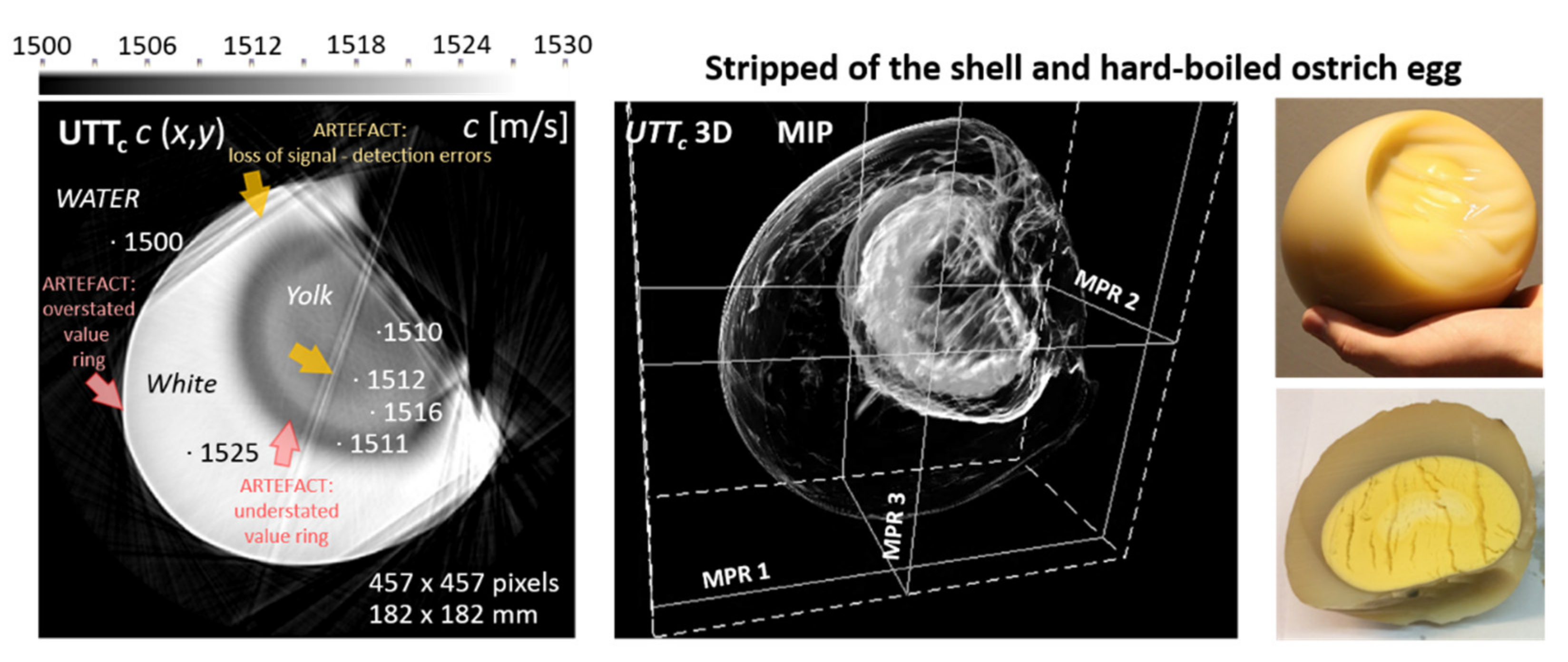
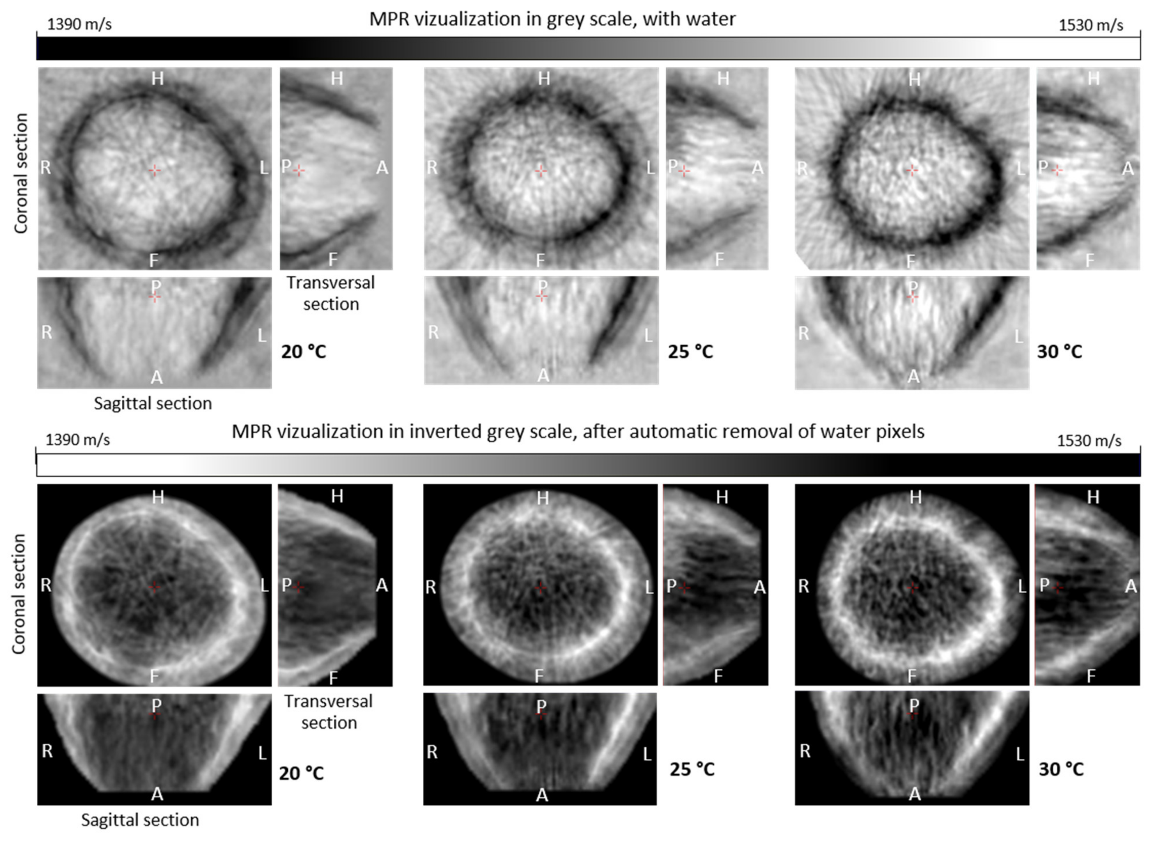
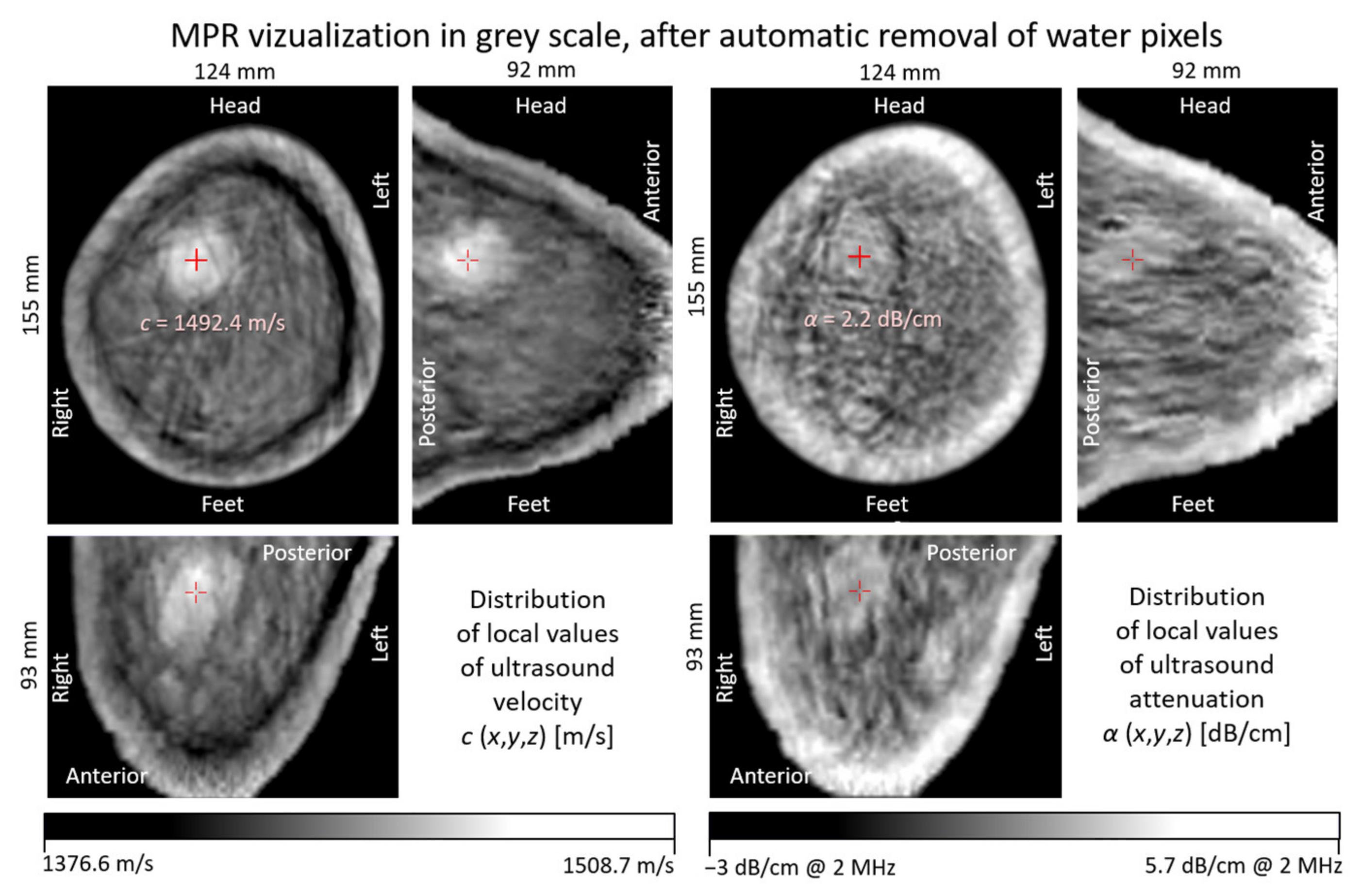
3.3. In Vivo Breast Measurements

An in vivo imaging study was performed using the hybrid UBT scanner on the left breast of a woman 35 years of age (Patient 1). The experienced radiologist diagnosed the breast of this patient as type C according to the ACR scale [50], non-uniformly dense, with areas of glandular tissue that can obscure focal lesions. Conventional USI and MMG did not show focal lesions (BI-RADS 1) or microcalcifications in this breast. The axillary fossae were found to be normal within the examined range. Due to its dense and heterogeneous structure, this breast is a difficult case for imaging. Therefore, it should show the refraction phenomenon of the ultrasound beam in UTT imaging.
Figure 16 shows ultrasound tomography projection velocity values (see Figure 3b) measured for the breast of the Patient 1 in water at 20 °C, 25 °C, and 30 °C, presented in parallel ray scanning geometry for a selected rotation angle (part of a sinogram) [22], for the first and third coronal cross-section from the breast base, respectively.
The cp values of the ultrasound projection velocity were determined as the ratio of the rectilinear path of the wave transition between successive pairs of transmitters and receivers to the measured transition time. Figure 17 shows quantitative ultrasound tomography images of the examined breast (Patient 1) in 3 mutually perpendicular sections (MPR) for water temperatures of 20 °C, 25 °C, and 30 °C, respectively, reconstructed based on ultrasound wave transit time data collected around the entire breast. In the images visualized in conventional gray scale (values increasing from black to white), the water pixels around the breast were left, and in the images visualized in inverse gray scale were removed automatically using a specially developed algorithm. The water segmentation is performed radially. The algorithm determines, for a given angle, two points at the water-breast and breast-water boundaries. The resulting polygon is blurred and then a mask is generated for the given cross-section. Water statistics of the ultrasound attenuation are used to detect breast boundaries. The algorithm runs automatically and is robust to noise due to the averaging procedures used. The segmentation algorithm does not introduce changes in the structure of the breast image. It is used to automatically detect the boundaries of a breast immersed in water and mask the water pixels.
Images show quantitative distributions of local ultrasound velocity values in individual sections. The images show characteristic “distortion rings” around the borders of breast cross-sections where the ultrasound velocity values are severely underestimated.

4. Discussion

Based on the calculations and measurements performed, it was found that in the ultrasound transmission tomography breast scanning procedure for the incidence angles of ultrasound wave beam rays at the water/breast border greater than about 50°, rays are increasingly refracted, resulting in the formation of a “ring of distortions” in the reconstructed breast cross-sectional image with distortions increasing in the direction of the cross-sectional border. The thickness of this ring decreases with the ratio of the breast diameter to the diameter of the measurement area. Of course, glandular tissue is not homogeneous and, in addition to the distortion associated with refractions at the cross-sectional boundary of the breast around, which will always occur, distortions associated with heterogeneity of the inner breast tissue may appear in different areas of the image (see Figure 4). Refractions can be particularly detrimental in the vertical plane due to the narrow beam of the ultrasound wave, for which diverging rays may not find their way from the transmitter to the receiver after refraction, due to negligible energy. This phenomenon is explained illustratively in Figure 18, which shows the spatial path of a refracted ultrasound wave beam ray through water and breast tissue from the selected sending transducer to the receiving one of ring array for the selected horizontal measurement plane, and the orthogonal projections of this path in the horizontal and vertical planes.
Refractions in the horizontal plane are larger the more the ray is angularly deviated from the diameter of the ring array, and they become significant from the value of the angle of incidence at the water/breast border of about 50°. Refractions in the vertical plane are greater the closer the measured breast section is to the end of the breast (closer to the nipple), but they also become significant from the value of the angle of incidence at the water/breast border of about 50°. Due to refractions in the vertical plane, the cross-section is always measured slightly higher than the geometric center of the transducer ring in their height. This distance increases as the ring array is lowered. On the basis of these calculations, it can be predicted that for a breast of standard size, ultrasound tomography images of its cross-section (especially ultrasound velocity distribution) in the region of about 2 cm from the nipple will have significant errors. To limit the possibility of obtaining large angles of incidence of ultrasound wave beam rays on the breast tip in the vertical plane, it would be necessary to slightly change the breast geometry during measurements by slight vertical stretching or loading of the nipple. It may be a problem in the case of small and dense breasts. Calculations also showed that significant minimization of refraction can be achieved at the water/skin/fat/breast interface by lowering the water temperature to about 32 °C. Furthermore, calculations showed that the length of time the breast was held at this temperature was not significant, since the results for the model that included the temperature gradient in the subcutaneous fat layer were not significantly different from the results for the model without the gradient.
It should be considered here that the calculations were performed for mean values of the parameters of breast skin, fat, and glandular tissue and a fixed thickness of the skin (2 mm) and the fat layer under the skin (5 mm). However, breasts have different structures, thicker or thinner skin, and skin layers, so the same improvement in image quality may not always be achieved in actual measurements. In this paper, it is impossible to analyze all combinations of ultrasound velocity values present in the breast structure. However, to preliminarily check the changes in intensity of the refraction phenomenon related to the possible changes in ultrasound velocities in the skin, fat, and glandular tissue of the breast, the parameter (∆opt) was calculated for selected minimum and maximum values (Table 1) using the developed model (Chapter 3.1).
It was also verified with the elaborated model that as the ultrasound velocity changes for a given tissue, the ∆opt values in the ranges determined in Table 1 change almost linearly. These results confirm the choice of an optimal water temperature of about 32 °C with respect to skin and fat. However, a low water temperature is beneficial for measurements of breasts with low ultrasound velocities in glandular tissue, and a high one for high velocities. The velocity of ultrasound in the glandular tissue of the breast has the greatest influence on the intensity of the refraction phenomenon, because in this case, the greatest changes in ∆opt values are observed.
Results of calculations and their conclusions were verified by ultrasound transmission tomography imaging of the entire breast volume in vivo, which was performed using a prototype of the hybrid UBT scanner developed by DRAMIŃSKI S.A. Distributions of ultrasound tomography projection velocity values in the examined breast (Figure 16) show the formation of characteristic distortion areas around the breast/water interface determined earlier using calculations for each of these three water temperature values. The “distortion ring” is the widest at 20 °C. Furthermore, velocity projection values in this case decreased by about 10 m/s in the entire breast region compared to measurements for other values of water temperature. It can be assumed that this is related to an increase in the measured values of the transit time due to a decrease in the amplitude of transmitted pulses along deflected beam rays as a result of the refraction. Reconstructed images of breast cross-sections measured at different water temperatures show significant similarity in the visualized inner breast structure (Figure 17). Some differences and changes of cross-section size may be due to the slightly different position of the breast because the need to change the water temperature prolonged the scanning time and there was no possibility to ensure a stable breast position for the patient in vivo for such a long time. It should be noted that the images of the local ultrasound velocity distribution in the breast cross-section are the most important because they are quantitative images and it is possible to obtain mapping with the accuracy better than 5 m/s, which helps distinguish cancerous lesions in the early stages. Images of the local ultrasound attenuation distribution are reconstructed with much lower accuracy because of weakening of the amplitude of ultrasonic pulses as a result of many additional phenomena (scattering, diffraction, losses due to beam divergence and transmission across inhomogeneity boundaries, etc.). The reconstructed breast images for different values of water temperature do not differ significantly in terms of quality, but for the case of a water temperature of 20 °C, the distortions in the form of diagonal lines are most visible. Such lines appear in the case of jumps of projection ultrasound velocity values in the sinogram. These values are determined by means of mean transit times of ultrasound pulses, similar to, e.g., the mean speed of driving a car along a road section from A to B. Such values change smoothly, not in a stepwise fashion, so jumps in value are caused by detection errors and signal fades. Thus, considering the analysis of the sinogram in Figure 16, the optimal water temperature should be chosen in the range of 25 °C ≤ T < 30 °C. The structure of the breast tissue in the images of Figure 17 is most pronounced for measurements at a water temperature of 30 °C. On the other hand, analyzing the “distortion ring”, it can be seen that the area with significantly underestimated ultrasound velocity values localized inside the ring (which obscures the glandular breast tissue area) is wider for the case of water temperature of 30 °C and the pixel values are smallest there. This is due to the large difference in ultrasound velocity values in water and breast tissue, which is unfavorable as analyzed earlier.

5. Practical Conclusions

Considering the conducted studies, it can be concluded that the water temperature for in vivo breast measurements using the developed UBT scanner can be set in the range of 25 °C ≤ T < 30 °C. It should be considered that in most cases, the in vivo breasts studied have a relatively low ultrasound velocity, less than 1500 m/s. For this reason, the UBT scanner currently uses a water temperature of 25 °C. It is also advantageous due to energy savings, a faster tank heating process, easier stabilization, and comfort for the patient. To further analyze the phenomenon of refraction, the authors perform complex calculations and measurements for a wide range of variations in ultrasonic velocity in the breast and refine the model developed.
Research has shown that the geometry of the breast should be slightly changed during measurements by vertical stretching or loading of the breast nipple to limit the possibility of obtaining large angles of incidence of ultrasound beam rays on the breast tip in the vertical plane. This can be done by using a sinker attached to the nipple with a rubber suction cup or by using a magnetic disc attracted by a magnet attached to an extension arm (Figure 19). The developers of ultrasound breast tomography scanners use different approaches. The authors used a suction cup with a weight of 350 g. The force to pull the breast in water in this way is so small that it does not cause permanent deformation of the breast or any pain to the patient. These improvements have been implemented in the prototype of the hybrid UTB scanner, enabling better imaging quality. In this way, there is no need for costly upgrades to the electronics of the device that would be necessary to register long signals, enabling the application of complex computational algorithms based on waveform or inverse theory. There is no doubt that significant improvements in image quality can be achieved with these methods, but it would necessitate the use of expensive and power-consuming high-bandwidth systems for fiber-optic data transmission, as well as graphics cards with GPU processors. In our applied solution, acquisition of fragments of received pulses is sufficient, which enables precise measurements of their transition time and pulse amplitude.
Figure 20 shows the results of ultrasound imaging of the left breast of a 66-year-old woman (Patient 2) in vivo using the UBT scanner prototype with sinker application (Figure 19), at a water temperature of 25 °C. Cross-sectional MPR images visualizing both velocity and attenuation distributions of ultrasound clearly show an area with values of these parameters increased compared to the surrounding tissue. This indicates a high probability of malignant carcinoma. Ultrasound examination performed by an experienced radiologist showed a solid hypoechoic tumor with blurred outlines 19 × 17 × 17 mm, which cancerous in nature. Histopathological examination showed an invasive carcinoma of the breast of no special type, grade 3 (high malignancy). The carcinoma occupied about 60% of the surface of the samples sent for examination.
Significant surges and negative values of attenuation on the borders of heterogeneous areas in UTT ultrasound attenuation images are the result of measurement errors, as the weakening of the amplitude of ultrasound wave pulses measured after passing through the breast is caused not only by attenuation but also by refraction, diffraction, anisotropy, reflection, scattering on heterogeneity borders, and beam divergence. Therefore, this image may be rather treated as a quantitative-qualitative one.
Based on the results obtained so far, it is anticipated that the hybrid ultrasound tomography scanner implemented by DRAMIŃSKI S.A. with appropriate fusion (compositing) of reconstructed images may contribute to the creation of a new standard for breast cancer diagnosis in the form of rapid and inexpensive screening tests that will result in information about the presence, baseline type, and location of breast cancer lesions along with the estimation of whether they are benign or malignant.

Author Contributions

Conceptualization: K.J.O.; methodology: K.J.O.; software: M.B.; validation: K.J.O., A.G., and M.B.; formal analysis: K.J.O.; investigation: K.J.O., M.B., A.W., and A.G.; resources: A.W.; data curation: M.B. and K.J.O.; writing—original draft preparation: K.J.O., A.G., and M.B.; writing—review and editing: K.J.O. and A.G.; visualization: K.J.O. and M.B.; supervision: A.W.; project administration: A.W. and A.G.; funding acquisition: A.W. All authors have read and agreed to the published version of the manuscript.

Funding

Research was performed as project POIR.01.01.01-00-1595/15, titled: “Development of a prototype of multimodal ultrasound tomography system for breast diagnosis” co-financed by the European Union from the European Regional Development Fund (Subtask 1.1.1—Industrial Research and Development Works conducted by Companies, Smart Growth 2014–2020 operational program), as part of the funding granted by the Polish National Center for Research and Development.

Institutional Review Board Statement

The study was performed according to the Declaration of Helsinki guidelines and was approved by the Bioethics Committee of the Warmia and Mazury Medical Chamber in Olsztyn (Resolution No. 2/2020/VII of 26 February 2020).

Informed Consent Statement

Informed consent was obtained from all subjects involved in the study. Patients participating in this study cannot be identified in any way from the information in this paper.

Conflicts of Interest

The authors declare no conflict of interest.

References

  1. Sung, H.; Ferlay, J.; Siegel, R.L.; Laversanne, M.; Soerjomataram, I.; Jemal, A.; Bray, F. Global Cancer Statistics 2020: GLOBOCAN Estimates of Incidence and Mortality Worldwide for 36 Cancers in 185 Countries. CA Cancer J. Clin. 2021, 71, 209–249. [Google Scholar] [CrossRef] [PubMed]
  2. Breast Cancer. Available online: https://www.who.int/news-room/fact-sheets/detail/breast-cancer (accessed on 21 March 2021).
  3. Zhang, B.-N.; Cao, X.-C.; Chen, J.-Y.; Chen, J.; Fu, L.; Hu, X.-C.; Jiang, Z.-F.; Li, H.-Y.; Liao, N.; Liu, D.-G.; et al. Guidelines on the diagnosis and treatment of breast cancer. Gland Surg. 2012, 1, 39–61. [Google Scholar] [CrossRef] [PubMed]
  4. Berrington de Gonzalez, A.; Berg, C.D.; Visvanathan, K.; Robson, M. Estimated risk of radiation-induced breast cancer from mammographic screening for young BRCA mutation carriers. J. Natl. Cancer Inst. 2009, 101, 205–209. [Google Scholar] [CrossRef] [PubMed] [Green Version]
  5. Lambertz, C.K.; Johnson, C.J.; Mongomery, P.G.; Maxwell, J.R. Premedication to reduce discomfort during screening mammography. Radiology 2008, 248, 765–772. [Google Scholar] [CrossRef] [PubMed] [Green Version]
  6. Saarenmaa, I.; Salminen, T.; Geiger, U.; Heikkinen, P.; Hyvärinen, S.; Isola, J.; Kataja, V.; Kokko, M.-L.; Kokko, R.; Kumpulainen, E.; et al. The effect of age and density of the breast on the sensitivity of breast cancer diagnostic by mammography and ultrasonography. Breast Cancer Res. Treat. 2001, 67, 117–123. [Google Scholar] [CrossRef]
  7. Kopans, D.B. Negative mammographic and US findings do not help exclude breast cancer. Radiology 2002, 222, 857–858. [Google Scholar] [CrossRef]
  8. Boyd, N.F.; Guo, H.; Martin, L.J. Mammographic density and the risk and detection of breast cancer. N. Engl. J. Med. 2007, 356, 227–236. [Google Scholar] [CrossRef] [Green Version]
  9. Kerlikowske, K.; Zhu, W.; Hubbard, R.; Geller, B.; Dittus, K.; Braithwaite, D.; Wernli, K.J.; Miglioretti, D.L.; O’Meara, E.S. Outcomes of screening mammography by frequency, breast density, and postmenopausal hormone therapy. JAMA Intern. Med. 2013, 173, 807–816. [Google Scholar] [CrossRef] [Green Version]
  10. Gøtzsche, P.C. Mammography screening is harmful and should be abandoned. J. R. Soc. Med. 2015, 108, 341–345. [Google Scholar] [CrossRef] [Green Version]
  11. Biller-Andorno, N.; Jüni, P. Abolishing Mammography Screening Programs? A View from the Swiss Medical Board. N. Engl. J. Med. 2014, 370, 1965–1967. [Google Scholar] [CrossRef] [Green Version]
  12. Berg, W.A.; Blume, J.D.; Cormack, J.B.; Mendelson, E.B.; Lehrer, D.; Böhm-Vélez, M.; Pisano, E.D.; Jong, R.A.; Evans, W.P.; Morton, M.J.; et al. Combined screening with ultrasound and mammography vs mammography alone in women at elevated risk of breast cancer. JAMA 2008, 299, 2151–2163. [Google Scholar] [CrossRef] [PubMed]
  13. Hooley, R.J.; Greenberg, K.L.; Stackhouse, R.M.; Geisel, J.L.; Butler, R.S.; Philpotts, L.E. Screening US in patients with mammographically dense breasts: Initial experience with Connecticute Public Acte 09-41. Radiology 2012, 265, 59–69. [Google Scholar] [CrossRef] [PubMed]
  14. Zonderland, H.M.; Coerkamp, E.G.; Hermans, J.; van de Vijver, M.; Van Voorthuisen, A.E. Diagnosis of breast cancer: Contribution of US as an adjunct to mammography. Radiology 1999, 213, 413–422. [Google Scholar] [CrossRef] [PubMed]
  15. Corsetti, V.; Ferrari, A.; Ghirardi, M.; Bergonzini, R.; Bellarosa, S.; Angelini, O.; Bani, C.; Ciatto, S. Role of ultrasonography in detecting mammographically occult breast carcinoma in women with dense breasts. Radiol. Med. 2006, 111, 440–448. [Google Scholar] [CrossRef]
  16. Warren, R.M.L.; Pointon, L.; Thompson, D.; Hoff, R.; Gilbert, F.J.; Padhani, A.; Easton, D.; Lakhani, S.R.; Leach, M.O. Reading protocol for dynamic contrast-enhanced MR images of the breast: Sensitivity and specificity analysis. Radiology 2005, 236, 779–788. [Google Scholar] [CrossRef] [PubMed] [Green Version]
  17. Duric, N. Ultrasound Tomography: A Breast Imaging Modality Whose Time Has Come. Med. Phys. 2015, 42, 3699. [Google Scholar] [CrossRef]
  18. Malik, B.; Terry, R.; Wiskin, J.; Lenox, M. Quantitative transmission ultrasound tomography: Imaging and performance characteristics. Med. Phys. 2018, 45, 3063–3075. [Google Scholar] [CrossRef] [PubMed] [Green Version]
  19. Gemmeke, H.; Hopp, T.; Zapf, M.; Caiser, C.; Ruiter, N.V. 3D Ultrasound Computer Tomography: Hardware Setup, Reconstruction Methods and First Clinical Results. Nucl. Instrum. Methods Phys. Res. A Accel. Spectrom. Detect. Assoc. Equip. 2017, 873, 59–65. [Google Scholar] [CrossRef]
  20. Opieliński, K.J.; Pruchnicki, P.; Szymanowski, P.; Szepieniec, W.K.; Szweda, H.; Świś, E.; Jóźwik, M.; Tenderenda, M.; Bułkowski, M. Multimodal ultrasound computer-assisted tomography: An approach to the recognition of breast lesions. Comput. Med. Imaging Graph. 2018, 65, 102–114. [Google Scholar] [CrossRef]
  21. Milewski, T.; Michalak, M.; Wiktorowicz, A.; Opieliński, K.; Pruchnicki, P.; Bułkowski, M.; Gielecki, J.; Jóźwik, M. Hybrid Ultrasound Tomography Scanner—A Novel Instrument Designed to Examine Breast as a Breast Cancer Screening Method. Biomed. J. Sci. Tech. Res. 2019, 14, 10822–10826. [Google Scholar] [CrossRef]
  22. Kak, A.C.; Slaney, M. Principles of Computerized Tomographic Imaging; Society for Industrial and Applied Mathematics: Philadelphia, PA, USA, 2001; p. 327. [Google Scholar] [CrossRef]
  23. Opieliński, K.J. Full Angle Ultrasound Spatial Compound Imaging. In Proceedings of the 7th Forum Acusticum, Kraków, Poland, 7–12 September 2014; European Acoustics Association: Madrid, Spain, 2014. [Google Scholar]
  24. Borowski, J.; Opieliński, K.J. Model of Multipath Propagation of Ultrasonic Pulses in Soft Tissue Using Divergent Beam Tomography Method. Vib. Phys. Syst. 2019, 30, 1–8. [Google Scholar]
  25. Glassner, A.S. An Introduction to Ray Tracing; Academic Press: Palo Alto, CA, USA, 1989. [Google Scholar]
  26. Andersen, A.H. A ray tracing approach to restoration and resolution enhancement in experimental ultrasound tomography. Ultrason. Imaging 1990, 12, 268–291. [Google Scholar] [CrossRef] [PubMed]
  27. Xiaolei, Q.; Takashi, A.; Hirofumi, N.; Haruka, I.; Satoshi, T.; Shu, T.; Shin-Ichiro, U.; Ichiro, S.; Yoichiro, M. Bent Ray Ultrasound Tomography Reconstruction Using Virtual Receivers for Reducing Time Cost. In Medical Imaging 2015: Ultrasonic Imaging and Tomography, Proceedings of SPIE Medical Imaging 9419, Orlando, Florida, USA, 21–26 February 2015; Johan, G., Bosch, N.D., Eds.; International Society for Optics and Photonics: Bellingham, WA, USA, 2015; Volume 94190F. [Google Scholar] [CrossRef]
  28. Podvin, P.; Lecomte, I. Finite difference computation of traveltimes in very contrasted velocity models: A massively parallel approach and its associated tools. Geophys. J. Int. 1991, 105, 271–284. [Google Scholar] [CrossRef]
  29. Hormati, A.; Jovanović, I. Robust Ultrasound Travel-Time Tomography Using the Bent Ray Model. In Medical Imaging 2010: Ultrasonic Imaging, Tomography, and Therapy, Proceedings of SPIE Medical Imaging 7629, San Diego, CA, USA, 13 February 2010; Stephen, J.D., McAleavey, A., Eds.; International Society for Optics and Photonics: Bellingham, WA, USA, 2010; Volume 76290I. [Google Scholar] [CrossRef] [Green Version]
  30. Labyed, Y.; Lianjie, H. Toward Real-Time Bent-Ray Breast Ultrasound Tomography Using GPUs. In Medical Imaging 2014: Ultrasonic Imaging and Tomography, Proceedings of SPIE Medical Imaging 9040, San Diego, CA, USA, 18–20 February 2014; Johan, G., Bosh, N.D., Doyley, M.M., Eds.; International Society for Optics and Photonics: Bellingham, WA, USA, 2014; Volume 90401N. [Google Scholar] [CrossRef]
  31. Yu, Y.; Yi, S.; Yue, Z.; Yang, X.; Jing, J.; Naizhang, F. A Modified Ray Tracing Method for Ultrasound Computed Tomography in Breast Imaging. In Proceedings of the 2020 IEEE International Instrumentation and Measurement Technology Conference (I2MTC), Dubrovnik, Croatia, 25–28 May 2020; IEEE: Piscataway, NJ, USA, 2020. [Google Scholar] [CrossRef]
  32. Tarantola, A. Inverse Problem Theory and Methods for Model Parameter Estimation; Society for Industrial and Applied Mathematics: Philadelphia, PA, USA, 2005. [Google Scholar] [CrossRef] [Green Version]
  33. Sandhu, G.; Li, C.; Roy, O.; Schmidt, S.; Duric, N. High-resolution quantitative whole-breast ultrasound: In vivo application using frequency-domain waveform tomography. In Medical Imaging 2015: Ultrasonic Imaging and Tomography, Proceedings of SPIE Medical Imaging 9419, Orlando, Florida, USA, DC, 21–26 Feb 2015; Johan, G., Bosch, N.D., Eds.; International Society for Optics and Photonics: Bellingham, WA, USA, 2015; Volume 94190D. [Google Scholar] [CrossRef]
  34. Taskin, U. Full-Waveform Inversion for Breast Ultrasound. Ph.D. Thesis, Delft University of Technology, Delft, The Netherlands, 2021. [Google Scholar]
  35. Javaherian, A.; Lucka, F.; Cox, B.T. Refraction-corrected ray-based inversion for three-dimensional ultrasound tomography of the breast. Inverse Probl. 2020, 36, 41. [Google Scholar] [CrossRef]
  36. Andersen, A.H.; Kak, A.C. Digital ray tracing in two-dimensional refractive fields. J. Acoust. Soc. Am. 1982, 72, 1593–1606. [Google Scholar] [CrossRef]
  37. Andersen, A.H. Ray linking for computed tomography by rebinning of projection data. J. Acoust. Soc. Am. 1987, 81, 1190–1192. [Google Scholar] [CrossRef]
  38. Langan, R.T.; Lerche, L.; Cutler, R.J. Traycing of rays through a heterogeneous media: An accurate and efficient procedure. Geophysics 1985, 50, 1456–1465. [Google Scholar] [CrossRef]
  39. Lytle, R.J.; Dines, K.A. Iterative Ray Tracing between Boreholes for Underground Image Reconstruction. IEEE Trans. Geosci. Remote Sens. 1980, GE-18, 234–240. [Google Scholar] [CrossRef]
  40. Duck, F.A. Physical Properties of Tissue—A Comprehensive Reference Book; Academic Press: London, UK, 1990. [Google Scholar]
  41. Kossof, G.; Fry, E.K.; Jellins, J. Average velocity of ultrasound in the human female breast. J. Acoust. Soc. Am. 1973, 53, 1730–1736. [Google Scholar] [CrossRef]
  42. Opieliński, K.; Gudra, T. Main error sources in ultrasound transmission tomography imaging. In Proceedings of the 16th International Congress on Acoustics and 135th Meeting Acoustical Society of America, Seattle, DC, USA, 20–26 June 1998; American Institute of Physics: College Park, MD, USA, 1998; Volume 2, pp. 407–408. [Google Scholar]
  43. Opieliński, K.; Gudra, T. Ultrasound transmission tomography image distortions caused by the refraction effect. Ultrasonics 2000, 38, 424–429. [Google Scholar] [CrossRef]
  44. Opieliński, K.J. Ultrasonic parameters of hen’s egg. Mol. Quantum Acoust. 2007, 28, 203–216. [Google Scholar]
  45. Lewitt, R.M. Reconstruction algorithms: Transform methods. Proc. IEEE 1983, 71, 390–408. [Google Scholar] [CrossRef]
  46. Pope, T.L., Jr.; Read, M.E.; Medsker, T.; Buschi, A.J.; Brenbridge, A.N. Breast skin thickness: Normal range and causes of thickening shown on film-screen mammography. J. Can. Assoc. Radiol. 1984, 35, 365–368. [Google Scholar] [PubMed]
  47. The Foundation for Research on Information Technologies in Society (IT’IS). Available online: https://itis.swiss/virtual-population/tissue-properties/database/acoustic-properties/ (accessed on 10 January 2022).
  48. Radiopaedia. Available online: https://radiopaedia.org (accessed on 14 November 2019).
  49. Sato, Y.; Shiraga, N.; Nakajima, S.; Tamura, S.; Kikinis, R. Local Maximum Intensity Projection (LMIP): A New Rendering Method for Vascular Visualization. J. Comput. Assist. Tomogr. 1988, 22, 912–917. [Google Scholar] [CrossRef] [PubMed] [Green Version]
  50. D’Orsi, C.J. 2013 ACR BI-RADS Atlas: Breast Imaging Reporting and Data System, 5th ed.; American College of Radiology: College Park, MD, USA, 2013; p. 689. [Google Scholar]
Figure 1. Dependence of: (a) angle of refraction of the ultrasonic wave at the water/breast interface from the angle of incidence; (b) coefficient of transmission of the ultrasonic wave Dp through a circular cross-section of a breast immersed in water.
Applsci 12 03578 g001
Figure 2. Simulation of the refraction effect of ultrasound beam rays along the path from the transmitter to the receiver placed on an axis at a distance of 300 mm opposite each other and moved with a constant step (10 mm) along the circular cross-section of a cylinder (breast) immersed in water: (a) n = 0.991; (b) n = 1.009.
Applsci 12 03578 g002
Figure 3. Calculated values of ultrasound velocity projection through a circular cross-section of a cylinder without and with refraction for refraction indices: (a) n = 0.991; (b) n = 1.009. The ultrasound velocity projection value cp is determined as the ratio of the rectilinear path of the wave passage between the transmitter and receiver to the measured (simulated) transit time.
Applsci 12 03578 g003
Figure 4. Artefacts in the example of reconstruction of ultrasound velocity distribution image in the cross-section of an ostrich egg measured with the prototype of the hybrid UBT scanner.
Applsci 12 03578 g004
Figure 5. Three different scenarios for the passage of ultrasound beam rays in divergent geometry from the transmitter to four different receivers of a multi-element ultrasound ring array through a breast with a subcutaneous fat layer, immersed in water.
Applsci 12 03578 g005
Figure 6. Temperature dependence of ultrasound velocity in water and fat.
Applsci 12 03578 g006
Figure 7. View of the prototype of the hybrid UBT scanner developed by DRAMIŃSKI S.A., the ultrasonic ring array, and elementary transducers.
Applsci 12 03578 g007
Figure 8. Layered computational models of the water/skin/breast fat/breast glandular tissue media: (a) assuming body temperature in the breast fat layer; (b) assuming a linear temperature gradient changing from water temperature to body temperature in the breast fat layer.
Applsci 12 03578 g008
Figure 9. Results of calculating the refraction of the incident ultrasonic wave beam rays from water on curvilinear breast layers without temperature gradient in fat (see the model in Figure 8a) for angles of beam rays in the range of respectively of 5–37° (first row), as well as for the maximum possible values of the angle of beam ray still allowing this ray to pass through all layers (second row), for temperatures of 20 °C, 25 °C, 30 °C, and 35 °C (rows).
Applsci 12 03578 g009
Figure 10. Results of calculating the refraction of the incident ultrasonic wave beam rays from water on curvilinear breast layers with temperature gradient in fat (see the model in Figure 8b) for angles of beam rays in the range of, respectively, 5–37° (first row), as well as for the maximum possible values of the angle of beam ray still allowing this ray to pass through all layers (second row), for temperatures of 20 °C, 25 °C, 30 °C, and 35 °C (rows).
Applsci 12 03578 g010
Figure 11. Results of the calculation of the parameter ∆opt as a function of the angle α I N for different values of the water temperature and both models: without (a) and with temperature gradient (b) in the fat layer.
Applsci 12 03578 g011
Figure 12. Results of optimization of the water temperature obtained with the developed models for the parameter ∆opt: without (a) and with temperature gradient (b) in the fat layer.
Applsci 12 03578 g012
Figure 13. Geometric computational models for investigating the area of greatest refraction of an ultrasound wave in a cross-section of a breast submerged in water, inside a ring array, successively in the horizontal and vertical planes.
Applsci 12 03578 g013
Figure 14. Visualization of results of calculations of the area of the largest ultrasound wave refractions in the breast section for 3 different diameters of these sections (Db = 180, 120, 40 mm) in the horizontal plane.
Applsci 12 03578 g014
Figure 15. Visualization of results of calculations of the area of the largest refractions of the ultrasound wave in the breast section for 3 different diameters of these sections (Db = 180, 120, 40 mm) in the vertical plane.
Applsci 12 03578 g015
Figure 16. Visualization of ultrasound tomography projection velocity values for the breast of Patient 1 tested in vivo in water at 20 °C, 25 °C, and 30 °C (measured data), presented in parallel ray geometry for the selected rotation angle: left—for the first coronal section from the breast base; right—for the third coronal section from the breast base.
Applsci 12 03578 g016
Figure 17. Reconstructed MPR images of breast cross-sections of Patient 1 studied in vivo at a water temperature of 20 °C, 25 °C, and 30 °C presented in standard and inverted grayscale, respectively, and before and after automatic removal of water pixels around the breast (H—head, F—feet, L—left, R—right, P—posterior, A—anterior).
Applsci 12 03578 g017
Figure 18. Illustrative representation of the spatial path of the refracted ultrasound wave ray through water and breast tissue from the selected sending transducer to the receiving transducer of the ring array and the selected horizontal measurement plane, and orthogonal projections of this path in the horizontal and vertical planes.
Applsci 12 03578 g018
Figure 19. Simple ways to stretch a breast submerged in a tank with a sinker or with a magnet.
Applsci 12 03578 g019
Figure 20. In vivo imaging results of the left breast of a 66-year-old woman (Patient 2) with the nipple sinker application, at 25 °C water temperature using a prototype of the USB hybrid scanner.
Applsci 12 03578 g020
Table 1. Values of the ∆opt parameter calculated for selected minimum and maximum ultrasound velocity in skin, fat, and breast glandular tissue.
Water
Temperature [°C]
Skin @ cFat = 1470 m/s
cBreast = 1515 m/s
Fat @ cSkin = 1624 m/s
cBreast = 1515 m/s
Breast @ cSkin = 1624 m/s
cFat = 1470 m/s
c M i n M a x [ m / s ] opt [°] c M i n M a x [ m / s ] opt [°] c M i n M a x [ m / s ] opt [°]
2015373.7514123.981430−6.57
17201.9514902.7415649.30
2515372.3314122.561430−7.65
17200.6914901.3915647.71
3015371.1514121.381430−8.58
1720−0.3814900.2615646.38
3515370.1614120.381430−9.36
1720−1.281490−0.6915645.28
The ranges of variation in ultrasound velocity were selected based on the literature [40,47].
Publisher’s Note: MDPI stays neutral with regard to jurisdictional claims in published maps and institutional affiliations.

