1. Introduction
The Yangtze River Delta urban agglomeration in China consists of Shanghai and three provinces, Jiangsu, Zhejiang, and Anhui. In recent years, to promote the regional integrated development and construct rail transit networks in Shanghai, Nanjing, Suzhou and other cities, the construction of rail transit within and between cities is being vigorously developed. For example, the Suzhou Metro Line S1 project connecting Shanghai and Suzhou is under construction [
1,
2].
The Yangtze River Delta is located in the lower reaches of the Yangtze River in China, bordering the Yellow Sea and the East China Sea. Consequently, it is an alluvial plain formed before the Yangtze River enters the sea and is mainly composed of soft clay and sandy soil [
3,
4]. Among soils, the mucky-silty clay is characterized by high moisture content and low strength coupled with high compressibility and sensitivity, which is one of the stratigraphic characteristics of the Yangtze River Delta and challenges underground engineering construction [
5,
6]. For example, the shield has become the prevalent choice for tunneling activities in congested urban areas due to its safe working environment and small disturbance to the surrounding ground. However, when the shield tunnels in (very) soft clay, both the construction and post-construction period face the challenges of ground and tunnel settlement control, i.e., Shanghai Metro Line 1 has experienced a maximum settlement of 288 mm within 12.5 years [
7], Nanjing Metro Line 10 has experienced a maximum settlement of 240 mm within 5.75 years after the track system was constructed [
8], and Daiba tunnels suffered from excessive settlement due to the ongoing consolidation of the soft clay layer caused by adjacent construction [
9]. This is mainly because the tunneling disturbance greatly reduces the strength of the soil with high sensitivity and aggravates the construction settlement. In addition, the deep and highly compressive soil may also produce larger consolidation settlements [
10,
11]. Moreover, construction parameters, such as the grouting volume and the grouting pressure, have a great influence on the soil loss and the distribution of the pore water pressure, which also affects the short-term and consolidation settlement of the ground and tunnel [
12,
13,
14]. Moreover, poor shield posture and segment posture always accompany shield tunneling in soft soil, which induces segment seal failure and increases post-construction settlement [
15,
16,
17].
Scholars conducted extensive research to explore the ground and tunnel settlement in soft soil, including both construction period settlement [
18,
19,
20,
21,
22,
23,
24,
25,
26] and long-term settlement [
27,
28,
29,
30,
31,
32]. The short-term subsidence was studied mostly based on the Peck and modified Peck empirical formulas based on similar engineering experience, and also includes theoretical and numerical studies based on formation losses. The research on long-term settlement mainly focused on the effects of consolidation, secondary consolidation, and train loads, which were mostly studied using two-dimensional numerical simulations and on-site monitoring. However, field data were difficult to obtain and mostly used for qualitative analysis. Moreover, the modified Cambridge model, which is most suitable for describing the stress-strain relationship of soft clay, was rarely used in previous numerical simulation studies, especially in the three-dimensional numerical model of long-term settlement. In addition, long-term settlement is closely related to construction disturbance and parameters. However, it is rare to discuss the influence of construction parameters, such as grouting amount, grouting pressure, and segment leakage caused by poor construction, on the long-term settlement of the tunnel.
Based on the project of Suzhou rail transit line S1, this paper presented a three-dimensional numerical model to evaluate the short-term and long-term displacement of the soft soil and tunnel when constructing shield tunnels in soft soil. The model adopted the modified Cam-clay model to simulate the behavior of soft soil and can consider the grouting parameters and the water leakage of the assembled segment lining. In addition, the simulation results were compared with the field observations, and the sensitivity of key parameters was analyzed.
2. Project Overview and Geotechnical Conditions
Suzhou Metro Tunnel-Line S1, constructed in Kunshan, Suzhou, is located in the east of Suzhou and borders with Shanghai, and is a system of 41.36 km long twin tunnels and a total of 28 stations spaced at an average interval of 1.523 km along the line. Each tunnel is 6.6 m in outer diameter and 5.9 m in inner diameter. The tunnels with an axis depth of 9–25 m are constructed with a precast concrete lining, and the length of each lining section is 1.2 m.
According to the site investigation results, most of the land area in Suzhou is quaternary sediments with a total thickness of more than 150 m, and the quaternary deposit within 70 m construction depth along Line S1 primarily consists of silty clay, mucky-silty clay, and sandy soil.
Figure 1 shows the detailed stratigraphic profile between Zhanlanzhongxin station and Xihuanlu station. In this interval, the shield was mainly excavated in the soil layer of the mucky-silty clay ②
y, which is widely distributed in the east (the top 460 rings) and characterized by high water content and compressibility coupled with low permeability and shear strength.
Earth pressure balance machines fabricated by China Railway Construction Heavy Industry Corporation Limited were used to the tunnel between Zhanlanzhongxin station and Xihuanlu station. The EPB shields with a total weight of 530 t were 9100 mm long, with a cutter head diameter of 6860 mm. In addition, the diameter and skin thickness of the front, middle, and rear shields were 6810 and 50 mm, 6800 and 40 mm, and 6790 and 40 mm, respectively.
The section of the 240th ring of the left line tunnel was set as the monitoring section LR240 as shown in
Figure 1, and the surface settlement and tunnel displacement of the monitoring section LR240 were monitored during and after the construction.
3. Three-Dimensional Finite Element Analysis Model
3.1. Numerical Model
The size of the model is 120 m in length, 60 m in width, and 40 m in height. From top to bottom, the soil consists of silty clay ②
1, mucky-silty clay ②
y, and silty clay ⑤
1. The thickness of silty clay ②
1 is 4 m, and the thickness of mucky-silty clay ②
y and silty clay ⑤
1 can vary. The soil element adopted the three-dimensional eight-node linear element C3D8P with pore pressure, and the number of meshes is 119,200, as shown in
Figure 2.
This study used the homogeneous circle method to simulate the tunnel, which indicated a homogeneous cylinder was used to simulate the tunnel, and the elastic modulus of concrete was reduced to equate the weakening effect of the joints and bolts on the stiffness. The length of the tunnel is 120 m, with a total of 100 rings. The buried depth of the tunnel is 14.7 m, the outer and inner diameters of the tunnel are 6.6 m and 5.9 m, respectively. Moreover, the excavation gap is 0.13 m, and the influence of grouting material was simulated by a grouting equivalent layer with a thickness of 0.13 m. Moreover, both the tunnel lining and the grouting equivalent layer adopted the three-dimensional eight-node non-coordinating linear element C3D8I, and the number of grids is 14,800, as shown in
Figure 3.
Both the tunnel excavation process and the long-term consolidation process adopted fluid-solid coupling analysis steps, and used the “model change” function to realize soil excavating and lining construction. The disturbance of shield excavation can be simulated by the stress releasing method and the convergent displacement method. In this paper, the convergent displacement method was used to simulate the shield excavation. The convergent displacement method was to preset the convergent displacement during excavation, which can highlight the main contradiction and reflect the disturbance of shield construction.
Due to the existence of soil loss volume, the soil movement mode at the excavation profile can be simplified as the soil at the excavation profile is converging to the periphery of the shield. As shown in
Figure 4, by assuming that the convergent displacement of the top of the excavation profile is
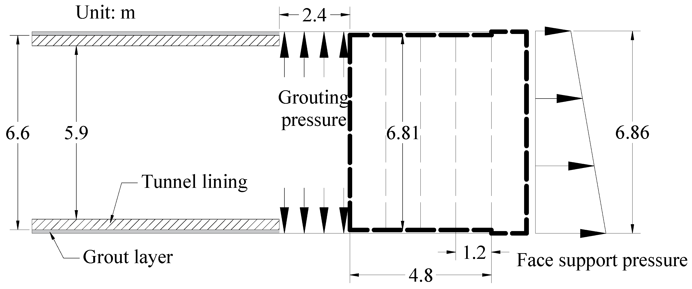
, the convergent displacement of the bottom is zero, and the center of the shield periphery is the convergent point of the displacement, the soil displacement converging mode was obtained. In this case, the excavation diameter of the shield machine used is 6.86 m, and the diameter of the shield periphery is 6.81 m, which adopted the diameter of the shield tail. Consequently, the convergence displacement at any angle can be calculated by Equation (1) proposed by Zhang (2016).
where
is the convergent displacement of the vault (m);
is the convergent displacement at any polar angle (m);
is the excavation radius of the shield machine (m);
is the outer radius of the shield tail(m);
is the polar angle.
The following methods were used to simulate the shield construction process. First, the support pressure of the tunnel face in the front was added. Then, the “model change” function, which can kill the soil corresponding to a ring segment, was used to simulate the excavation in the front. At the same time, the lining and grouting layer at the rear was activated, and the grouting pressure to simulate the effect of simultaneous grouting was applied. Furthermore, the supporting pressure of the tunnel face adopted the active water and soil pressure corresponding to the depth of the soil layer, and the grouting pressure adopted a uniform force, as shown in
Figure 5. In the soft soil, the tunneling speed of the shield is relatively slow, which is generally controlled at 40~80 mm/min. Further considering the segment assembly time, about eight rings are excavated per day. Converted to continuous excavation in the numerical model, one ring is excavated approximately every 3 h.
3.2. Material Properties
The modified Cam-clay model was proposed by Roscoe and Burland (1968) at the University of Cambridge, UK, based on the triaxial test of normally consolidated clay and weakly overconsolidated clay. This model can consider the hydrostatic yield characteristics, compressive stiffness, and shear shrinkage of geotechnical materials, which is suitable for normally consolidated soils or weakly overconsolidated soils, as well as strongly overconsolidated soils and other viscous soils. Considering that the soft soil involved in this project is normally consolidated soil, it is appropriate to adopt the modified Cam-clay model to simulate the stress-strain relationship of the soils.
The main parameters of the modified Cam-clay model can be obtained by the geological survey report, and the specific conversion formulas are as follows.
where
is the slope of the initial isotropic normal consolidation curve INCL in the semi-logarithmic coordinate system;
is the slope of the initial compression rebound curve in the semi-logarithmic coordinate system;
is the spatial slope of the critical state line CSL;
is the compression factor;
is the rebound index;
is the effective internal friction angle of the soil.
According to the modified Cam-clay model theory, its yield surface can be written as:
Furthermore, it can be rewritten as:
where
and
are the average effective stress and deviator stress, respectively;
is the initial value of
.
According to the modified Cam-clay model theory, the void ratio
of the soil in the consolidated state is:
where
is the intercept of the normal consolidation curve INCL.
In the ABAQUS/standard, if the soil uses the Gravity type to add gravity load, the material density should use the dry density of the soil. Therefore, when the saturated density of soil is known, the dry material density
is:
where
is the saturated density of the soil;
is the density of water.
The soil properties of at monitoring section shown in
Table 1 were mainly obtained from triaxial tests and penetration testing, and the corresponding parameters of the modified Cam-clay model are shown in
Table 2:
The linear elastic constitutive model was used for the tunnel structure and grouting layer. The segments were made of C50 concrete. While considering the influence of the joints of the shield tunnel segments, the elastic modulus of C50 concrete needs to be reduced. Based on the lining loading test of staggered assembling on the ground, the “Standard Segments for Shield” (1994) formulated by the Japan Road Association stipulated that the stiffness reduction coefficient
can be taken as 0.6~0.8. In this paper,
is taken as 0.8. The specific parameters are shown in
Table 3. In addition, the parameters of the grouting layer are shown in
Table 4.
3.3. Boundary Conditions
The boundary conditions of the model were composed of geometric boundary conditions and hydraulic boundary conditions. For the geometric boundary condition, the top surface in this model was a free boundary, and both the bottom and side surfaces were set with normal constraints. In addition, in order to simulate soil consolidation, reasonable hydraulic boundary conditions need to be set. In this model, the top surface of the soil was set as a free drainage boundary, and both the side and bottom surfaces were set as a constant head boundary. Moreover, the model was given an initial pore pressure field, which can be calculated by the water pressure. While the water level was set on the ground surface, and the water pressure at any depth h is .
3.4. Tunnel Seepage Conditions
The shield tunnel is composed of segments assembled, and the quality of assembling has a great influence on the waterproof performance of the tunnel structure. Concerning “Technical Specifications for Waterproofing of Underground Engineering” (GB50108-2008) [
33], the waterproofing conditions of the tunnel must meet the secondary waterproofing, which indicates that the average seepage volume of the tunnel is not more than 0.05 L/(m
2·d). When the water leakage volume of the tunnel exceeds the above index, the settlement of the ground and the tunnel will be aggravated. To consider this factor, tunnel leakage was achieved by directly defining the seepage velocity on the surface or node. Furthermore, the “Concentrated pore fluid” load was used to simulate the local leakage of the tunnel, and the “Surface pore fluid” load was used to simulate the full-peripheral penetration of the tunnel.
4. Comparing Simulating Results with Monitoring Results
The section of the 240th ring of the left line tunnel was set as the monitoring section LR240. To verify the reliability of the numerical model, the model calculation results were compared with the field monitoring results.
Table 5 showed the parameters required for numerical model calculation, which was consistent with the construction parameters corresponding to the on-site monitoring section LR240. Considering the large disturbance during the construction process, the leakage conditions of the tunnel adopted the four-level standard, which indicated that the average seepage volume of the entire tunnel project was 2 L/(m
2·d).
During tunnel construction, the ground settlement and tunnel deviation of the monitoring section LR240 were recorded and compared with the simulated results in
Figure 5 and
Figure 6. To distinguish between short-term and long-term settlement, the short-term settlement mentioned in this paper refers to the settlement that occurs during the period directly affected by the shield construction steps, including cutter head excavation, shield body passage, lining construction, and grouting. The long-term settlement refers to the settlement that occurs during the consolidation period of soil and slurry after all construction steps are completed. Thus, the 240th ring segment lining that was assembled corresponds to the sixth day in the model. In addition, the first 12 days were defined as the construction phase, in which the consolidation function was not turned on in the model; 13 to 90 days were defined as the consolidation phase, in which the consolidation function was turned on in the model.
As the filed observations show in
Figure 6, there was a settlement in the ground surface, which was basically within 5 mm, before the segment lining was assembled. This part of the settlement is mainly due to volume loss in front of the excavation front and around the shield periphery. After the segments were assembled, the surface began to bulge and reached the maximum bulge value of 5 mm after three days, which was caused by the rebound effect of unloading soil and grouting material. Furthermore, the results indicated that the grouting material and disturbed soil around the segment began to consolidate and coagulate after three days. As a result, the consolidated settlement occurred. Although the secondary grouting will cause a rebound of the formation, consolidation settlement will continue to occur subsequently. Compared with the simulation results, it can be found that the time-history law of the simulation results and the monitoring results were consistent, which can be summarized as follows: before the segment was assembled, the stratum subsided, and after assembling, the stratum first uplifted and then subsided. However, there were some differences between numerical simulation and field monitoring data in short-term settlement and long-term settlement. First, the simulated subsidence when the shield tail passes was larger than the monitored value. This is mainly because the shield often excavates in the soft soil with the head loaded and the tail raised, which is due to the heavy cutter head and the low strength of the subsoil, and the raised tail will lift the ground uplift. However, this effect was not considered in the numerical simulation. In addition, the monitored consolidation occurred about three days after the shield tail passed, which was related to the coagulation time of the grouting. However, in the numerical simulation, the time for consolidation to occur was artificially set (six days after the shield tail passes through), and the grouting material hardening was not considered. The reason the simulated consolidation time was longer than that in the field is to fully present the whole process of settlement during construction. Moreover, the consolidation settlement in the field was larger than the simulation. This can be explained by the fact that the sub-consolidation settlement and the consolidation and cementation effects of grout were not considered in the numerical model, which are also main components of long-term surface settlement.
After the segments were assembled, the deviation of the tunnel was monitored for three days, as shown in
Figure 7. The results showed that the segment was in a continuous floating stage within three days after the segment was assembled, and the maximum floating amount reached 28 mm, which is consistent with the development of the simulation results. It should be noted that the floating amount of the segment in the field was larger than the simulated value. This was mainly related to the state of the grouting material around the segment. The longer the time and length of the segment lining in the liquid grouting material are, the greater the floating amount of the segment. The results indicated that the segment at the monitoring section was affected by the grouting material for about three days, which is longer than the assumed time and length of the grouting acted on the segment lining in the numerical model.
The horizontal settlement trough of the ground surface after the shield machine passed completely during the construction period was compared with the field observation. As shown in
Figure 8, the simulated surface settlement trough presented a standard bell-shaped curve, with a maximum settlement of −10.98 mm directly above the tunnel axis. The simulated results were consistent with the value and distribution of the monitored surface settlement trough. However, the monitored surface settlement trough had a certain asymmetry, which was different from the simulation results. The possible reason is that the shield machine has a large horizontal axis deviation during the tunneling process, and the numerical model established in this paper does not consider the deviation of the shield machine from the tunnel axis.
5. Sensitivity Analysis
Shield construction in the soft soil layer will cause short-term and long-term settlement of the ground surface and tunnel. For the long-term settlement of surface and lining, it is difficult to analyze theoretically because it is affected by many factors, such as the thickness of soft soil under the tunnel and tunnel leakage. In addition, due to the high time cost of on-site monitoring methods, the field study of long-term settlement prediction is not suitable. In contrast, a sophisticated numerical model considering a variety of influencing factors can simulate the long-term settlement through fluid-solid coupling, which can greatly reduce the time and cost of field monitoring.
Based on the established model, this paper systematically analyzed the effects of grouting pressure, grouting filling rate, the thickness of soft soil under the tunnel, and tunnel leakage on the short-term and long-term settlement of the surface and tunnel. The parameters and values of the sensitivity analysis are shown in
Table 6.
5.1. Grouting Pressure
The vertical displacements of the surface above the tunnel axis and tunnel top at y = 60 m in the model were selected to monitor, and the developments of the displacements of the surface and tunnel within 90 days under different grouting pressures were obtained, as shown in
Figure 9.
The results showed that the surface displacement during the construction period and consolidation period were less affected by the grouting pressure applied during construction as shown in
Figure 9a. Compared with the surface settlement, the displacement of the tunnel top was slightly affected by the grouting pressure, especially the settlement during the construction period. As shown in
Figure 9b, the floating amount of the tunnel increased with the grouting pressure increasing, while the settlement during the consolidation period was basically the same, which led to a positive correlation between the cumulative settlement of the tunnel and its settlement during the construction period.
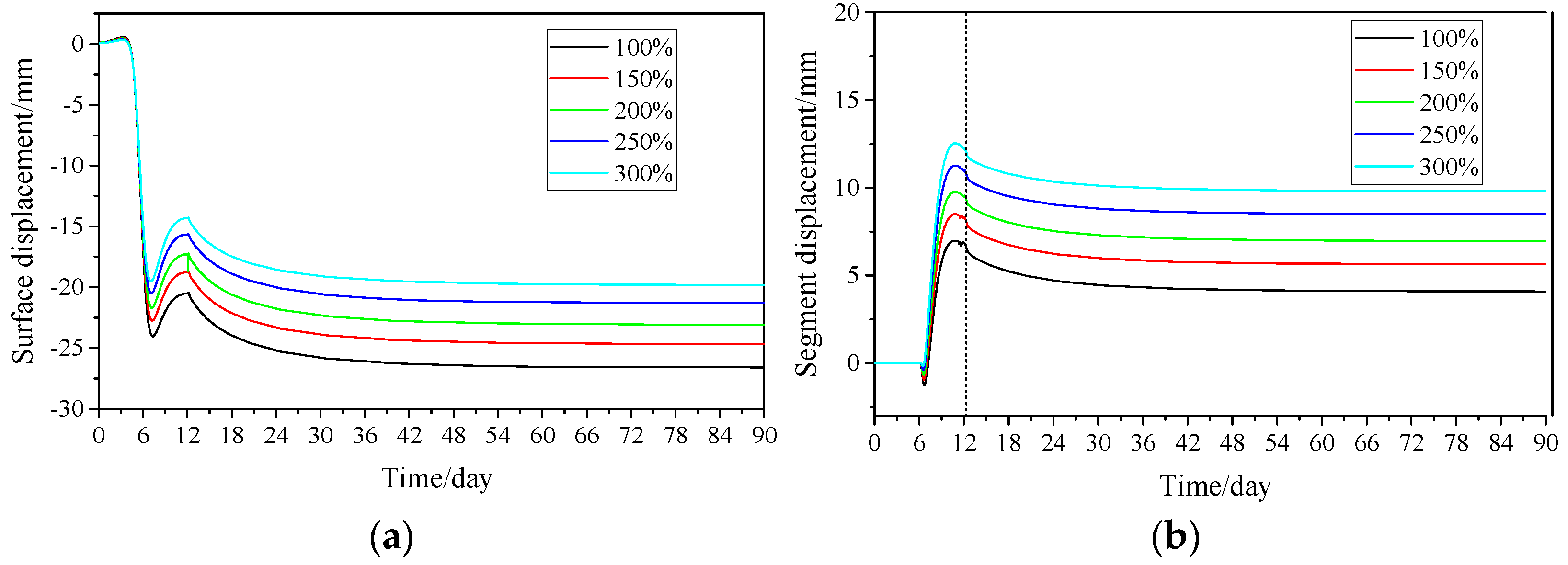
5.2. Grouting Filling Rate
The vertical displacements of the surface above the tunnel axis and tunnel reach the top at y = 60 m within 90 days under different grouting filling rates were obtained, as shown in
Figure 10. The grouting filling rate had a significant impact on the settlement of ground and tunnel during construction and consolidation, especially for the construction period. As shown in
Figure 10a, the surface settlement decreased while the grouting filling rate increased, which was mainly because the ground loss caused by the excavation during construction decreased significantly with the high grouting filling rate. In addition, the greater buoyancy of the tunnel induced by the high grouting rate also reduced part of the ground settlement, as shown in
Figure 10b. For the time for deformation stability of stratum and tunnel, there was no significant difference with different grouting filling rates, which indicated that the consolidation time mainly depended on the soil surrounding the shield and was less affected by the grouting filling rate.
5.3. Thickness of Underlying Soft Soil
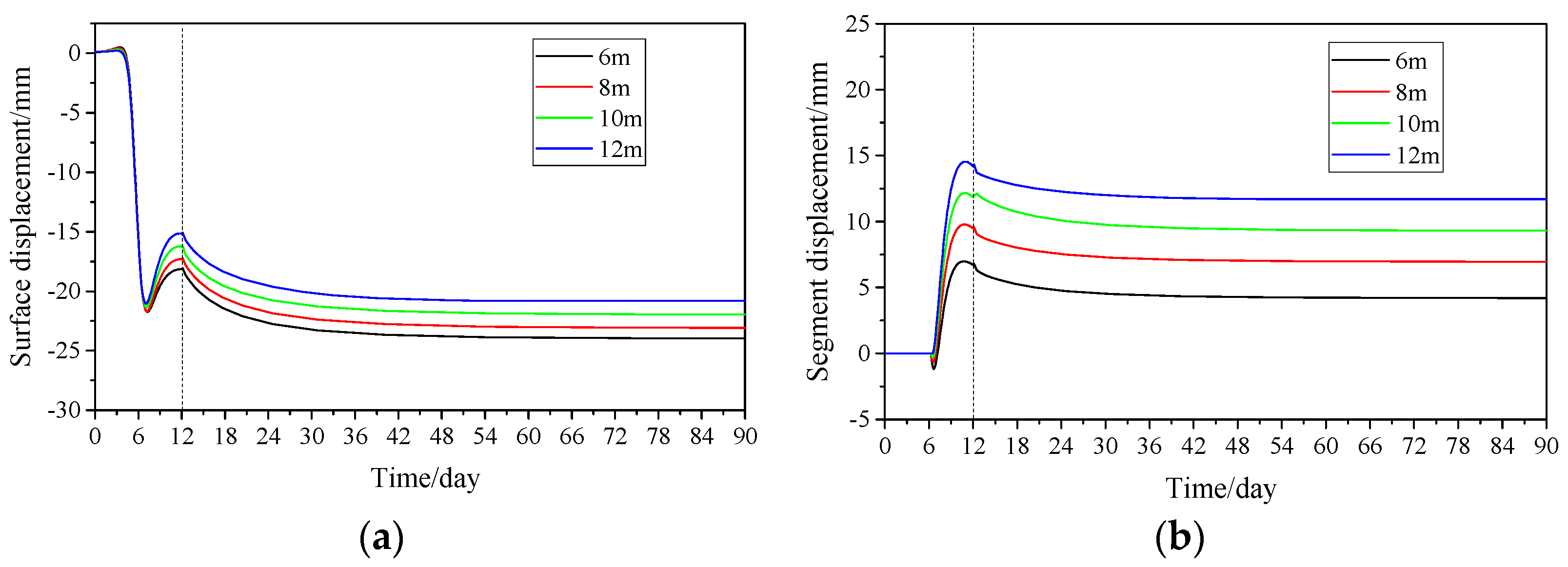
Super soft soil such as mucky-silty clay has a significant impact on the short-term and long-term settlement of the ground and the tunnel. This section presents the settlement of the ground and tunnel with different thicknesses of soft soil under the tunnel as shown in
Figure 11, and the results indicated that the thickness of the underlying soft soil layer had a significant effect on the displacement of the ground and the tunnel.
As shown in
Figure 11a, the surface displacement during the construction period decreased with the thickness of the underlying soft soil increasing. However, there was no obvious difference in the consolidation settlement corresponding to the thickness of the underlying layer during the consolidation period. The results indicated that the consolidation area of the soft soil around the tunnel with different thicknesses was relatively close when the tunnel seepage water conditions were the same. Compared with the ground displacement, the tunnel exhibited obvious uplift during the construction period. As shown in
Figure 11b, the amount of uplift increased with the increase of the thickness of the underlying soft soil layer, which was consistent with the surface deformation during the construction period, while in the consolidation stage, there was no significant difference in tunnel settlement (about 3 mm) and consolidation time (about 60 days) under different underlying layer thicknesses. Consequently, it can be inferred that the deep underlying soft layer does not increase the consolidation settlement of the stratum and tunnel under the conditions of tunnel Grade 4 waterproofing in theory, but will cause significant ground uplift and tunnel floating during construction, which played a major role in the cumulative deformation of the ground and the tunnel.
5.4. Tunnel Leakage
The long-term settlement of the soft soil and the embedded tunnel is significantly affected by the seepage conditions of the lining. According to the “Technical Specification for Waterproofing of Underground Engineering” (GB50108-2008), the first-level standard for tunnel waterproofing is that no water seepage is allowed, the second-level standard is that the average seepage volume of the tunnel is not more than 0.05 L/(m2·d), and the fourth-level standard is the average seepage of the tunnel, which is no more than 2 L/(m2·d). For urban subways tunnels, the waterproof requirement is the second-level standard. However, due to the poor posture control of the shield machine and the poor quality of the segment assembled during the construction period, the shield tunnel may experience greater water leakage, which will aggravate the long-term settlement of the ground and the tunnel. This section divided the leakage of the tunnel into full-peripheral seepage and partial seepage and discussed the influence of tunnel seepage conditions on the long-term deformation of the ground and the tunnel.
Figure 12 shows the surface and tunnel settlements during the consolidation period under different tunnel seepage volumes, as shown in
Table 6 in the full-peripheral seepage condition. The results indicated that the tunnel seepage volume had a significant impact on the long-term displacement of the surface and tunnel. When the waterproof level of the tunnel reaches Grade II or above, the surface and the tunnel will not undergo consolidation settlement, on the contrary, a slight uplift will occur. This can be explained as follows: the soil around the tunnel cannot undergo consolidation settlement in the case of small tunnel leakage, because the tunnel seepage volume was too small to form an effective seepage path to change the pore water pressure and effective stress state of the soil around the tunnel. In this case, the displacement of the stratum and the tunnel was mainly controlled by the unloading rebound of the soil. In addition, from the perspective of the duration of consolidation, the time required for stabilizing increased with the tunnel leakage volume increasing, and the consolidation time for the maximum seepage volume was nearly 60 days.
In practice, local leakage is often more likely to occur than full-peripheral seepage. According to the requirements of “Technical Specification for Waterproofing of Underground Engineering” (GB50108-2008), the water leakage of a single leaking point is not more than 2.5 L/d.
Figure 13 showed the settlement of the stratum and the tunnel at different seepage positions. As shown in
Figure 13a, the surface consolidation settlement caused by the tunnel top leakage was the largest, and the surface settlement caused by the tunnel bottom leakage was the smallest. However, the tunnel consolidation settlement was the opposite of ground settlement. As shown in
Figure 13b, the tunnel settlement caused by the tunnel bottom leakage was the largest, and the tunnel settlement caused by the tunnel top leakage was the smallest. A possible reason was the redistributed pore water pressure and effective stress caused by different tunnel seepage points were different. For the conditions of tunnel top leakage, the stress redistribution area of the soil was above the tunnel, where the largest consolidation settlement of the ground occurred. Therefore, in this case, the surface settlement was the largest. For the condition of the tunnel bottom leakage, the stress redistribution area of the soil was mainly under the tunnel, which led to a larger consolidation settlement of the soil under the tunnel and induced a greater displacement of the tunnel. However, due to the transfer of the soil consolidation area, the consolidation settlement of the soil above the tunnel and the resulting surface settlement was significantly reduced. For the leakage of the sidewall of the tunnel, the consolidation settlements of the ground surface and tunnel were between those that occurred in the condition of the leakage condition of the tunnel top and bottom.
Based on the above analysis, when the tunnel reached Grade II waterproofing and above, the long-term settlement of the ground and the tunnel basically did not occur. However, once the Grade II waterproof requirement was not met, the consolidation settlement of the ground and tunnel will occur. In addition, the impact of local leakage in the tunnel on the long-term settlement of the ground and tunnel was significant. Especially for tunnels, the bottom leakage will aggravate the long-term settlement of the tunnel and cause significant uneven settlement, which is very detrimental to the operation of the tunnel.
6. Conclusions and Discussions
To evaluate the short-term and long-term displacement of the soft soil and tunnels when constructing a metro in soft soil, this paper presented a three-dimensional numerical model based on the project of Suzhou rail transit line S1. The modified Cam-clay model was used to simulate the strain-softening effect of soft soil. Moreover, the proposed model can consider the grouting parameters and the water leakage of the assembled segment lining, which have a great impact on the settlement of soft soil and tunnel during and after construction. In addition, the simulation results of the project of Suzhou rail transit line S1 were compared with the field observations, and the sensitivity of key parameters was carried out by the established numerical model. The results showed that the grouting volume, the thicknesses of soft soil under the tunnel, and the tunnel leakage conditions have a significant impact on the stratum and tunnel settlement. Notably, the tunnel leakage conditions have the greatest impact on the long-term consolidation settlement. Moreover, when the tunnel meets the secondary waterproof requirements, the increase of the thicknesses of soft soil under the tunnel basically does not increase the long-term settlement of the stratum and the tunnel but increases the corresponding short-term settlement.
Compared with previous studies, this paper obtained the entire history of surface and tunnel displacement by linking construction period factors and long-term settlement. The obtained results can be used to guide the construction of similar projects. However, the proposed three-dimensional model has some shortcomings, such as the inability to consider the consolidation and cementation of the grouting material, the sub-consolidation settlement of subsoil, and the attitude of the shield machine, which also have significant effects on the short-term and long-term settlement of tunnels and formations. Thus, related research needs to be further studied in the future.
Author Contributions
Conceptualization, H.J. and D.Y.; methodology, H.J.; software, D.Z.; validation, H.J.; formal analysis, H.J.; investigation, H.J.; resources, S.Z.; data curation, H.J.; writing—original draft preparation, H.J.; writing—review and editing, H.J. and D.Y.; visualization, H.J.; supervision, D.Y.; project administration, D.Y.; funding acquisition, D.Y. All authors have read and agreed to the published version of the manuscript.
Funding
This research received was funded by the Natural Science Foundation “Joint Fund Project” (No. U1834208).
Institutional Review Board Statement
Not applicable.
Informed Consent Statement
Not applicable.
Data Availability Statement
The data presented in this study are available from the corresponding author upon request.
Acknowledgments
The authors gratefully acknowledge financial support from the Natural Science Foundation “Joint Fund Project” (No. U1834208).
Conflicts of Interest
The authors declare no conflict of interest.
References
- Huang, Q.; Huang, H.; Ye, B.; Zhang, D.; Zhang, F. Evaluation of train-induced settlement for metro tunnel in saturated clay based on an elastoplastic constitutive model. Undergr. Space 2018, 3, 109–124. [Google Scholar] [CrossRef]
- Jin, H.; Yuan, D.; Jin, D.; Zhou, S.; Wang, X. Fluidization Behavior of Soft Soil Induced by Shield Construction. Appl. Sci. 2021, 11, 9627. [Google Scholar] [CrossRef]
- Wang, Z.; Wong, R.C.; Li, S.; Qiao, L. Finite element analysis of long-term surface settlement above a shallow tunnel in soft ground. Tunn. Undergr. Space Technol. 2012, 30, 85–92. [Google Scholar] [CrossRef]
- Shen, S.-L.; Wu, H.-N.; Cui, Y.-J.; Yin, Z.-Y. Long-term settlement behaviour of metro tunnels in the soft deposits of Shanghai. Tunn. Undergr. Space Technol. 2014, 40, 309–323. [Google Scholar] [CrossRef]
- Coussot, P.; Raynaud, J.-S.; Bertrand, F.; Moucheront, P.; Guilbaud, J.P.; Huynh, H.T.; Jarny, S.; Lesueur, D. Coexistence of Liquid and Solid Phases in Flowing Soft-Glassy Materials. Phys. Rev. Lett. 2002, 88, 218301. [Google Scholar] [CrossRef]
- Wang, Z.-F.; Shen, S.-L.; Ho, C.-E.; Kim, Y.-H. Investigation of field-installation effects of horizontal twin-jet grouting in Shanghai soft soil deposits. Can. Geotech. J. 2013, 50, 288–297. [Google Scholar] [CrossRef]
- Ng, C.W.W.; Liu, G.B.; Li, Q. Investigation of the long-term tunnel settlement mechanisms of the first metro line in Shanghai. Can. Geotech. J. 2013, 50, 674–684. [Google Scholar] [CrossRef]
- Di, H.; Zhou, S.; Xiao, J.; Gong, Q.; Luo, Z. Investigation of the long-term settlement of a cut-and-cover metro tunnel in a soft deposit. Eng. Geol. 2016, 204, 33–40. [Google Scholar] [CrossRef]
- Komiya, K.; Takiyama, K.; Akagi, H. Settlement behaviour of a shield tunnel constructed in subsiding reclaimed area. In Proceedings of the 5th International Conference on Geotechnical Aspects of Underground Construction in Soft Ground, Amsterdam, The Netherlands, 15–17 June 2006; pp. 239–244. [Google Scholar]
- Meng, F.-Y.; Chen, R.P.; Kang, X. Effects of tunneling-induced soil disturbance on the post-construction settlement in structured soft soils. Tunn. Undergr. Space Technol. 2018, 80, 53–63. [Google Scholar] [CrossRef]
- Jallow, A.; Ou, C.-Y.; Lim, A. Three-dimensional numerical study of long-term settlement induced in shield tunneling. Tunn. Undergr. Space Technol. 2019, 88, 221–236. [Google Scholar] [CrossRef]
- Komiya, K.; Soga, K.; Akagi, H.; Jafari, M.R.; Bolton, M.D. Soil consolidation associated with grouting during shield tunnelling in soft clayey ground. Geotechnique 2001, 51, 835–846. [Google Scholar] [CrossRef]
- Kasper, T.; Meschke, G. On the influence of face pressure, grouting pressure and TBM design in soft ground tunnelling. Tunn. Undergr. Space Technol. 2006, 21, 160–171. [Google Scholar] [CrossRef]
- Di, H.; Zhou, S.; Yao, X.; Tian, Z. In situ grouting tests for differential settlement treatment of a cut-and-cover metro tunnel in soft soils. Bull. Eng. Geol. Environ. 2021, 80, 6415–6427. [Google Scholar] [CrossRef]
- Afshani, A.; Li, W.; Oka, S.; Itoh, Y.; Akagi, H. Study of the long-term behavior of segmented tunnels in cohesive soil based on the circumferential joint opening. Tunn. Undergr. Space Technol. 2021, 120, 104210. [Google Scholar] [CrossRef]
- Wu, H.-N.; Shen, S.-L.; Chen, R.-P.; Zhou, A. Three-dimensional numerical modelling on localised leakage in segmental lining of shield tunnels. Comput. Geotech. 2020, 122, 103549. [Google Scholar] [CrossRef]
- Festa, D.; Broere, W.; Bosch, J. Kinematic behaviour of a Tunnel Boring Machine in soft soil: Theory and observations. Tunn. Undergr. Space Technol. 2015, 49, 208–217. [Google Scholar] [CrossRef]
- Peck, R.B. Deep excavations and tunnelling in soft ground. In Proceedings of the 7th International Conference on Soil Mechanics and Foundation Engineering, Mexico City, Mexico, 1 January 1969; Volume 4, State of the Art Volume. pp. 225–290. [Google Scholar]
- Mindlin, R.D. Force at a Point in the Interior of a Semi-Infinite Solid. Physics 1936, 7, 195–202. [Google Scholar] [CrossRef]
- Verruijt, A. A complex variable solution for a deforming circular tunnel in an elastic half-plane. Int. J. Numer. Anal. Meth. Geomech. 1997, 21, 77–89. [Google Scholar] [CrossRef]
- Mair, R.J.; Taylor, R.N.; Burland, J.B. Prediction of ground movements and assessment of risk of building damage due to bored tunnelling. In Geotechnical Aspects of Underground Construction in Soft Ground; Taylor & Francis/Balkema: Leiden, The Netherlands, 1996; pp. 713–718. [Google Scholar]
- Mair, R.J.; Taylor, R.N. Bored tunnelling in the urban environment. State-of-the-art Report and Theme Lecture. In Proceedings of the 14th International Conference on Soil Mechanics and Foundation Engineering, Hamburg, Germany, 6–12 September 1997; pp. 2353–2385. [Google Scholar]
- Ren, D.J.; Shen, S.L.; Arulrajah, A.; Wu, H.N. Evaluation of ground loss ratio with moving trajectories induced in double-O-tube (DOT) tunnelling. Can. Geotech. J. 2018, 55, 894–902. [Google Scholar] [CrossRef]
- Broere, W.; Festa, D. Correlation between the kinematics of a tunnel boring machine and the observed soil displacements. Tunn. Undergr. Space Technol. 2017, 70, 125–147. [Google Scholar] [CrossRef] [Green Version]
- Pinto, F.; Whittle, A.J. Ground movements due to shallow tunnels in soft ground. I: Analytical solutions. J. Geotech. Geoenviron. Eng. 2013, 140, 04013040. [Google Scholar] [CrossRef] [Green Version]
- Li, Z.; Luo, Z.; Xu, C.; Tan, J. 3D fluid-solid full coupling numerical simulation of soil deformation induced by shield tunnelling. Tunn. Undergr. Space Technol. 2019, 90, 174–182. [Google Scholar] [CrossRef]
- Zhang, Z.X.; Liu, C.; Huang, X.; Kwok, C.Y.; Teng, L. Three-dimensional finite-element analysis on ground responses during twin-tunnel construction using the URUP method. Tunn. Undergr. Space Technol. 2016, 58, 133–146. [Google Scholar] [CrossRef] [Green Version]
- Cao, Y.; Jiang, J.; Xie, K.-H.; Huang, W.-M. Analytical solutions for nonlinear consolidation of soft soil around a shield tunnel with idealized sealing linings. Comput. Geotech. 2014, 61, 144–152. [Google Scholar] [CrossRef]
- Cui, Z.-D.; Ren, S.-X. Prediction of long-term settlements of subway tunnel in the soft soil area. Nat. Hazards 2014, 74, 1007–1020. [Google Scholar] [CrossRef]
- Bian, X.C.; Zeng, E.X.; Chen, Y.M. Long-term settlements of soft soil ground induced by train traffic loadings. Rock Soil Mech. 2008, 29, 2990–2996. [Google Scholar]
- Gang, W.E.I. Research on theoretical calculation of long-term ground settlement caused by shield tunneling. Chin. J. Rock Mech. Eng. 2008, 27, 2960–2966. [Google Scholar]
- Xie, X.; Tian, H.; Zhou, B.; Li, K. The life-cycle development and cause analysis of large diameter shield tunnel convergence in soft soil area. Tunn. Undergr. Space Technol. 2021, 107, 103680. [Google Scholar] [CrossRef]
- B50108-2008; Technical Specifications for Waterproofing of Underground Engineering. Ministry of Housing and Urban Rural Development of the People’s Republic of China: Beijing, China, 2008.
Figure 1.
Geological profile.
Figure 1.
Geological profile.
Figure 2.
Schematic diagram of stratum grid division.
Figure 2.
Schematic diagram of stratum grid division.
Figure 3.
Schematic diagram of grid division of tunnel and grouting layer.
Figure 3.
Schematic diagram of grid division of tunnel and grouting layer.
Figure 4.
Schematic diagram of the convergent displacement method.
Figure 4.
Schematic diagram of the convergent displacement method.
Figure 5.
Schematic diagram of shield tunnel excavation.
Figure 5.
Schematic diagram of shield tunnel excavation.
Figure 6.
Simulated and monitored surface displacement time-history curves.
Figure 6.
Simulated and monitored surface displacement time-history curves.
Figure 7.
Simulated and monitored segment displacement time-history curves.
Figure 7.
Simulated and monitored segment displacement time-history curves.
Figure 8.
Simulated and monitored surface subsidence trough.
Figure 8.
Simulated and monitored surface subsidence trough.
Figure 9.
Displacement of surface and tunnel under different grouting pressure. (a) Development of surface displacement with time; (b) Development of segment displacement with time.
Figure 9.
Displacement of surface and tunnel under different grouting pressure. (a) Development of surface displacement with time; (b) Development of segment displacement with time.
Figure 10.
Displacement of surface and tunnel under different grouting filling rate. (a) Development of surface displacement with time; (b) Development of segment displacement with time.
Figure 10.
Displacement of surface and tunnel under different grouting filling rate. (a) Development of surface displacement with time; (b) Development of segment displacement with time.
Figure 11.
Displacement of surface and tunnel under the different thickness of the soft underlying layer. (a) Development of surface displacement with time; (b) Development of segment displacement with time.
Figure 11.
Displacement of surface and tunnel under the different thickness of the soft underlying layer. (a) Development of surface displacement with time; (b) Development of segment displacement with time.
Figure 12.
Displacement of surface and tunnel under different tunnel seepage volume. (a) Development of surface displacement with time; (b) Development of segment displacement with time.
Figure 12.
Displacement of surface and tunnel under different tunnel seepage volume. (a) Development of surface displacement with time; (b) Development of segment displacement with time.
Figure 13.
Displacement of surface and tunnel under different seepage points. (a) Development of surface displacement with time; (b) Development of segment displacement with time.
Figure 13.
Displacement of surface and tunnel under different seepage points. (a) Development of surface displacement with time; (b) Development of segment displacement with time.
Table 1.
Parameters of the soil layer.
Table 1.
Parameters of the soil layer.
| Stratum | | (°) | | | | |
|---|
| Silty clay②1 | 1.72 | 20 | 0.35 | 5.5×10⁻⁷ | 0.245 | 0.038 |
| Mucky-silty clay②y | 1.82 | 22.3 | 0.45 | 6.5×10⁻⁷ | 0.299 | 0.042 |
| Silty clay⑤1 | 1.82 | 26.1 | 0.3 | 7.5×10⁻⁷ | 0.286 | 0.037 |
Table 2.
Parameters of the Cambridge model of the soil layer.
Table 2.
Parameters of the Cambridge model of the soil layer.
| Stratum | | | | |
|---|
| Silty clay②1 | 0.106 | 0.017 | 0.772 | 1.33 |
| Silty silty clay②y | 0.13 | 0.018 | 0.869 | 1.63 |
| Silty clay⑤1 | 0.124 | 0.016 | 1.031 | 1.49 |
Table 3.
Parameters of the lining.
Table 3.
Parameters of the lining.
| Material | Density (g/cm3) | Elastic Modulus (kPa) | Poisson’s Ratio |
|---|
| Lining | 2.5 | 2.76×10⁷ | 0.2 |
Table 4.
Parameters of the grouting materials.
Table 4.
Parameters of the grouting materials.
| Material | Density (g/cm3) | Elastic Modulus (GPa) | Poisson’s Ratio |
|---|
| grouting layer | 1.8 | 3.5 | 0.25 |
Table 5.
Parameters for simulating.
Table 5.
Parameters for simulating.
| Items | Thickness of Weak Underlying Layer, Hs (m) | Grouting Pressure, pg (kPa) | Grouting Filling Rate, GFR (%) | Average Seepage Volume
|
|---|
| Values | 2 | 280 | 150 | 2 |
Table 6.
Parameters for sensitivity analysis.
Table 6.
Parameters for sensitivity analysis.
| Items | Values |
|---|
| Grouting pressure, pg (kpa) | 280 (240; 260; 280; 300) |
| Grouting filling rate, GFR (%) | 200 (100; 150; 200; 250; 300) |
| Thickness of underlying soft soil, Hs (m) | 8 (6; 8; 10;12) |
| Average seepage volume, vs (L/(m2·d)) | 2 (0.05; 0.5; 2; 3) |
| Publisher’s Note: MDPI stays neutral with regard to jurisdictional claims in published maps and institutional affiliations. |
© 2022 by the authors. Licensee MDPI, Basel, Switzerland. This article is an open access article distributed under the terms and conditions of the Creative Commons Attribution (CC BY) license (https://creativecommons.org/licenses/by/4.0/).


