Abstract
As the development of hydrodynamic torque converters (HTCs) points toward increasing the pump input power and pump rotation speed, the negative effects of cavitation are worsening. Most studies focus on suppressing fluid machinery cavitation to attenuate the negative effects of cavitation, such as noise, vibration, and blade damage. Therefore, we proposed two stator cavitation suppression slotting methods to suppress stator cavitation in HTCs: (1) slotting both sides of the pressure and suction sides and (2) slotting one side of the suction side. The key design parameters are analyzed, including the slot width and slot position of the stator blade. Findings show that a wider slot enlarges the mass flow rate ventilation through the slot, thus reducing the cavitation risk but decreasing the hydrodynamic performance. The most effective slot position for the second proposed method (slotting one side of the suction side) is between S0.15 (stator suction side dimensionless distance 0.15 location) and S0.6 (stator blade suction side); here, the stator cavitation can be suppressed completely. The capacity factor (Tbg) and torque ratio (K) are decreased by 6.81% and 3.23%, respectively, under the stalling speed ratio, whereas the stator cavitation almost completely disappears. Therefore, the new method of slotting one side of the stator suction side completely suppresses the stator cavitation and significantly shortens the cavitation duration. The new method of slotting one side of the blade suction side can serve as a reference for turbomachinery design.
1. Introduction
A hydrodynamic torque converter (HTC) is a closed turbomachine that is widely used in construction machinery, cars, and buses due to its torque multiplication and vibration isolation. A simple torque converter consists of three elements: a pump driven by an engine, a turbine connected to an output shaft, and a stator affixed to a hub. HTCs are being developed to have high launching performance, high rotational speed, and high pump input power, which can easily trigger the onset of cavitation. This will worsen the deterioration of hydrodynamic performance caused by cavitation. Therefore, many researchers have studied transient cavitation in turbomachinery and its cavitation suppression.
Flow control technology can significantly improve the overall hydrodynamic performance of fluid machinery. In recent years, flow control technology has been widely applied to the design of turbomachinery cascades. Moshfeghi added a split blade to horizontal-axis wind turbines and improved their aerodynamic performance by changing the split location and injection flow angle on the blade [1]. Shin proposed a slotted blade on the stator of an HTC; this design improved the input capacity factor by more than 15% relative to the baseline configuration [2]. Wu proposed a reasonable profile design of the suction side of the first stator and the slot width of the dual-blade stator of an HTC; this approach delayed the flow separation and enhanced the hydrodynamic performance [3]. Zao and Belamadi designed an arc-shaped internal slot with a transverse leading-edge tubercle structure and an equal-width straight slot, which allowed flow ventilation from the pressure side to the suction side of the blade [4,5,6]. They concluded that the slot width and slot slope greatly influenced the lift coefficient of the wind turbine blades. Liu added segmented blades to an HTC turbine; the blades were inspired by the wing design and could effectively improve the stall capacity factor (Tbg0) and the stall torque ratio (K0) [7].
Flow control technology has also been widely used to suppress cavitation in fluid machinery, as shown in Figure 1. Amromin processed local cavities on the leading edge of a hydrofoil suction side to regulate the pressure distribution therein and thus suppress cavitation [8]. Timoshevskiy investigated the mechanism of cloud cavitation and found that unstable shedding cavitation could be controlled effectively by continuous tangential liquid injection at different flow rates on the suction side of a hydrofoil [9]. Kawanami and Javadi placed obstacles and an artificial cavitation bubble generator on the suction side of a hydrofoil to suppress the unstable cavitation caused by the re-entrant jet [10,11]. Liu examined the influence of the blade profile on the development of stator cavitation and proposed a blade profile design to reduce cavitation and improve hydrodynamic performance [12,13]. According to Liu, a slot enabling flow ventilation from the nose to the suction side could alleviate the unstable cavitation behavior on the surface of a hydrofoil [14]. In the study of Choi, “J grooves” were added to the casing wall near the blade tip of an inducer; this design almost fully suppressed the cavitation surge under low flow rates [15]. Park proposed the placement of a flexible thread at the tip of a propeller, which could greatly suppress the generation of vortex cavitation at the propeller tip [16]. Slotted designs have a significant effect on suppressing fluid machinery cavitation. Therefore, the mechanism of fluid control technology in cavitation suppression should be understood, and effective fluid control technology solutions should be developed.

Figure 1.
Application of different slotting designs for cavitation suppression. (a) Cavitation suppression in hydrofoils; (b) cavitation-tolerant hydroturbine guide vane.
Previous researchers mostly focused on the traditional slotting method, which allows fluid intake on the pressure side and fluid ejection on the suction side of the blade. A large pressure gradient between the pressure side and the suction side will cause a jet to form on the suction side. This will worsen the load distribution on the blade surface, and the formation of high-speed jets will result in slot cavitation. Therefore, the conventional slotting method cannot fully suppress cavitation. Some researchers optimized the geometric profile or machined the groove structure near the leading edge of the suction surface to readjust the load distribution on the blade surface, but these methods cannot fully suppress cavitation, and they lead to increased local loss. The addition of an auxiliary flow control device can suppress a cavitation surge effectively, but it is difficult to apply to fluid machinery because of its high cost.
Given these shortcomings in suppressing cavitation, two suppression slot methods are proposed in this study: (1) The fluid is sucked in from the pressure side and ejected out of the suction side; both sides of the pressure and suction sides are slotted (Plan 1). (2) The fluid is sucked in from the downstream of the suction side and ejected out of the upstream of the suction side; only one side of the suction side is slotted (Plans 2–4).
The remaining content of this paper is organized as follows: Section 2 describes the computational fluid dynamics (CFD) calculation settings and transient cavitation simulation of the torque converter. It shows the distribution of cavitation in the flow field of the torque converter and the threat caused by cavitation. In Section 3, four slot designs are proposed for stator cavitation suppression, and the cavitation internal flow field and hydrodynamic performance of the slot solutions are compared. In Section 4, the authors quantitatively evaluate the cavitation risks of the four stator suppression slots, systematically discuss the stator cavitation under the various slot widths and slot positions, and reveal the cavitation suppression mechanism of stator cavitation. Then, the important conclusions of this paper are presented in Section 5. Exploring the influence of slot geometry on cavitation and proposing a practically valuable cavitation suppression method for HTC stators, this study offers reference value for turbomachine researchers.
2. Cavitation Simulation and Verification of HTC
2.1. Multiphase Model
A k-ω-based shear stress transport turbulence model is adopted because it can capture boundary layer details using a low Reynolds formulation with refined near-wall meshes and maintain a robust free shear flow solution. Cavitation is used as a transfer mechanism between the vapor and liquid phases to calculate the cavitation flow field inside the HTC. The fluid in the field always maintains mass and momentum conservation. The phase mass transfer rate equation between the vapor and liquid phases, that is, the cavitation equation, should be added. The governing equation is
The key to determining the cavitation flow field is to solve the growth and collapse rates, that is, the evaporation and condensation rates, of cavitation bubbles.
The bubble dynamics equation of cavitation is derived from the Rayleigh–Plesset equation, but the second-order and surface tension terms in the Rayleigh–Plesset equation are ignored. The equation is
Equation (2) provides a physical approach to introducing the effects of bubble dynamics into the cavitation model.
The Zwart–Gerber–Belamri cavitation model [17] is used; it calculates the total interphase mass transfer rate per unit volume () using the bubble density number (n). The mass change rate of a single bubble is
n is determined by
The net mass transfer is obtained by substituting the value of n into Equation (3).
When the local pressure is lower than the vapor pressure, cavitation bubbles are increased, and the vapor volume fraction is replaced by to yield [18]. The evaporation mechanism of cavitation in the flow field is controlled by , whose equation is
When the local pressure is greater than the vapor pressure, the cavitation collapses. The mechanism of cavitation condensation in the flow field is controlled by , which is expressed as
Because the condensation process of cavitation is slower than the vaporization process, the following empirical factors are assumed: = 50, = 0.01, = 5 × 10⁻⁴, and = 1 × 10⁻⁶ m [19,20,21].
A homogeneous multiphase condition is also assumed to simplify the model. Thus, the liquid and vapor phases share the same velocity and turbulence profiles.
2.2. CFD Model and Validation
The overall impeller and flow passage layout of the torque converter is shown in Figure 2. The purple parts in Figure 2 are the pump and the pump shell, the green parts are the turbine and the output shaft, the yellow part is the stator, and the cyan part is the hub. The pump is affixed to the engine flywheel and rotates at a rated speed of 2000 rpm. The turbine operates at different speed ratios with changes in the external load. The stator is fixed on the stationary hub. The torus diameter of the HTC is 375 mm. The detailed geometric parameters of the HTC cascade are shown in Table 1.
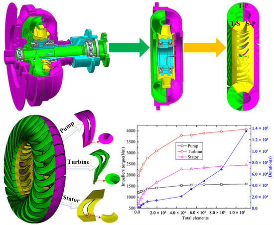
Figure 2.
HTC CFD model and grid independence study.

Table 1.
Structural parameters of HTC.
The grid near the blade wall is refined to capture the transient cavitation flow behavior around the blade. The height of the first-layer grid is set to 0.015 mm to ensure that the y+ value does not exceed 1. Additionally, the grid growth rate is 1.2, the wall grid height is 0.3 mm, and the prism grid has 12 layers. A hexahedral structured grid model of the HTC is depicted in Figure 2. This structural grid is generated using the software Ansys ICEM CFD, and the CFD simulation is performed using the software Ansys Fluent.
The full flow passage can be obtained from the geometric model of the torque converter through Boolean operations. The HTC is mainly composed of three computational domains: pump, turbine, and stator. The sliding mesh method is applied to deal with the real-time interaction between the upstream and downstream flows. Mesh interfaces are set up to enable the transmission of variables and parameters between adjacent impellers. The rotational speed of the pump is constant (), whereas that of the turbine is varied from 0 to 1600 rpm at 200 rpm increments in accordance with the different operating conditions. The time step of the HTC is critical for the transient cavitation simulation. The rotor–stator interaction (RSI) between the pump and the turbine is highly evident, whereas that between the turbine and the stator is smaller [22]. Because the RSI of the turbine–pump (T–P) interface is the strongest, the time step is determined in this study based on the pump rotational speed. If the time step is too large, the transient cavitation will not be obvious or the CFD result will not converge. If the time step is too small, the calculation time will be too long. In this study, the time step is calculated using Equation (8) [23,24]. Transient calculation is performed with a maximum of 15 loops for every time step, and the total time is 0.12 s, during which the pump can complete four revolutions. The time step is chosen to resolve the unsteadiness in one blade passage at the T–P interface with at least 10 time steps.
In Equation (8), represents the revolution speed of the pump (r/s) and represents the number of blades of the pump.
The detailed CFD simulation parameter setting of the HTC is shown in Table 2. On the shell of the stator–pump interface, the pressure level is set to 0.8 MPa, which is identical to the charge pressure during the test. On the shell of the turbine–stator interface, the pressure level is set to 0.4 MPa, which is identical to the back pressure of the HTC.
Table 2.
Detailed CFD model parameter setting.
Figure 2 shows the grid independence study. The CFD results indicate that when the mesh number reaches approximately 5 million, further refining the grid size does not strongly affect the outcome but will considerably increase the computational cost. Considering the balance between computational cost and accuracy, 3 is set as the final global grid size in this study.
The bench test of the torque converter is shown in Figure 3. The motor drives the pump and the turbine to rotate, and by adjusting different turbine rotational speeds, the torque converter is simulated to work under different working conditions. The rotational speed and torque of the pump and the turbine are obtained through the torque and rotational speed sensors on both sides of the pump and the turbine, and then the hydrodynamic performance of the torque converter can be obtained through calculation.

Figure 3.
Test rig for the HTC (1—drive dynamometer meter, 2—drive dynamometer, 3, 14—fluted disc, 4, 15—speed transducer, 5, 7, 11, 13—coupler, 6, 12—torque transducer, 8—oil inlet, 9—oil outlet, 10—torque converter, 16—dynamomter, 17—dynamometer meter, 18—mechanical brake, 19, 26—speed meter, 20, 25—torque meter, 21, 23—pressure meter, 22, 24—temperature meter).
After the simulation, the torque of each component is obtained; both noncavitation and transient cavitation CFD results are compared with the test data (Figure 4).
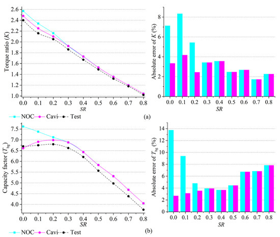
Figure 4.
Comparison of CFD results with test data under various SR conditions. (a) K and K absolute; (b) Tbg and Tbg absolute error.
The calculation formula for the hydrodynamic performance of the HTC is in [25,26]. The hydrodynamic performance of the torque converter is defined by the following operating parameters. The torque values of each impeller are averaged, and the hydrodynamic performance of the torque converter is calculated.
where and are the rotational speed (rpm) and and are the torque (Nm) of the pump and the turbine, respectively; D is the diameter of the torus (mm); and is the capacity of the power transmission ().
When speed ratio (SR) > 0.3, the two CFD results are consistent in terms of the capacity factor. When SR ≤ 0.3, the capacity factor of the test data increases with SR. The noncavitation result does not exhibit this trend, and a maximum error of 13.23% occurs under stall operating condition. On the contrary, the transient cavitation result achieves accurate prediction, with an error of less than 5% at a low SR. However, both the noncavitation and cavitation models overpredict the capacity factor under high-SR (SR > 0.3) operating conditions; this can be attributed to the disregard for the flow leakage at the shell and core in the HTC. When SR > 0.3, the K values of the two models are consistent with the trend of the capacity factor. When SR ≤ 0.3, the error of K considering the cavitation effect is less than 4%; by contrast, the K error without cavitation is up to 8%. The simulation results show that cavitation degrades the performance of both K and Tbg under low-speed-ratio operating conditions (SR ≤ 0.3). At high SRs (SR > 0.3), the noncavitation CFD result is consistent with the cavitation CFD findings. The reason is that cavitation only occurs at low SRs. Both the incidence angle and mass flow rate of the stator are large under low SRs, which is conducive to the generation of cavitation.
2.3. Transient Cavitation Behavior in HTC
After the CFD simulation of the transient cavitation flow field of the HTC, no measurable cavitation can be observed in the pump, where the pressure is high because of the high rotation speed under stall operating condition. Cavitation occurs near the leading edge of the turbine suction surface, and heavy cavitation appears near the leading edge of the stator suction surface. The stator cavitation is extremely unstable at low SRs. The cavitation distribution and cavitation process of the stator domain at SR = 0 are depicted in Figure 5. The stator cavitation undergoes periodic processes of inception, development, shedding, and collapse.
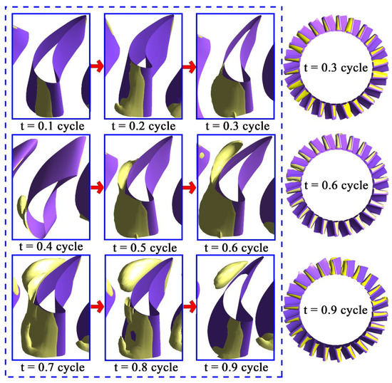
Figure 5.
Periodic cavitation process in stator domain under stall operating condition.
Cavitation is also found near the leading edge of the turbine suction surface of the HTC, as shown in Figure 6. The difference from the stator cavitation is that the turbine cavitation is stably attached; no detached bubbles are observed. The attached cavitation is formed in the shell of the turbine and gradually expands to the core as a result of the high velocity and large incidence angle.

Figure 6.
Evolution of 10% vapor volume fraction distribution in turbine domain under stall operating condition.
3. Application of Suppression Slot in Stator Cascade
3.1. Design Scheme of Stator Internal Slots
Four suppression slots are created on the stator blades, as shown in Figure 7, to suppress the stator cavitation. The detailed parameters of the suppression slots are listed in Table 3. Slot Plan 1 is created by slotting both sides of the pressure and suction sides. The high-pressure flow on the pressure side is jetted into the low-pressure region of the suction side to adjust the surface pressure of the blade, thereby suppressing the cavitation. In Table 3, P0.1 (S0.3) represents the position where the dimensionless distance from the leading edge to the trailing edge of the pressure (suction) surface is 0.1 (0.3). Therefore, P0.1–S0.3 means the slotting is conducted between the 0.1 position of the pressure surface and the 0.3 position of the suction surface of the stator. Slots Plans 2–4 were made by slotting one side of the suction side only. The high-pressure flow on the suction surface downstream is transported to the low-pressure region of the suction surface upstream to modify the surface pressure of the blade, thus suppressing the cavitation.
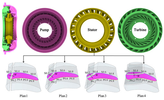
Figure 7.
HTC and slot geometric model.
Table 3.
Design parameters of suppression slots.
3.2. Hydrodynamic Performance Comparison of Slot Designs
The hydrodynamic performance of the HTC with the different suppression slots is shown in Figure 8. K deteriorates over the entire SR range after the suppression slots are added to the stator blade. Slot Plan 3 shows the greatest K0 degradation with the widening of the slot and the decrease in the mass flow rate in the mainstream domain. By contrast, Plan 1 exhibits the smallest K0 degradation relative to the baseline. The Tbg curve shows that the addition of the suppression slot heavily degrades Tbg. Under the overall operating conditions, except that the Tbg values of Plan 4 under SR = 0.7 and 0.8 are higher than the baseline, the Tbg values of all cases are greatly reduced. Plan 4 shows the greatest Tbg0 degradation, followed by Plan 3 and then Plan 1. Although the addition of the stator suppression slot compromises the hydrodynamic performance of the torque converter, it suppresses the generation of cavitation.
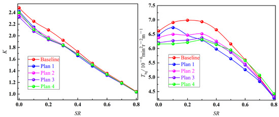
Figure 8.
Comparison of time-averaged K and Tbg with various suppression slots.
The cavitation distribution of the stator with the different suppression slots is shown in Figure 9. After the suppression slots are placed, the stator cavitation shifts from being an unstable cloud cavitation to being a stably attached cavitation, and the cavitation volume is greatly reduced. As shown in Figure 9, the cavitation of Plan 1 includes three types of cavitation, attached cavitation (located near the suction front edge of the stator), slot cavitation (located at the outlet of the suppression slot), and blade tail cavitation (at the trailing edge of the pressure side of the stator). Cavitation on the leading edge of the blade covers only half of the blade in the spanwise direction. Figure 9 shows that Plan 2 cavitation still covers the entire stator blade near the leading edge of the suction surface. In addition, the cavitation in the stator domain belongs to the attached cavitation. In Figure 9, the area covered by the cavitation of Plan 3 is smaller than that covered by Plan 2 cavitation due to the widening of the slot. The cavitation in the stator domain still belongs to the attached cavitation. The difference is that, as shown in Figure 9, the stator cavitation of Plan 4 is almost completely suppressed. There are only a few scatter cavitations on the stator blades, and there is no attached cavitation, and the stator cavitation is suppressed to a great extent.

Figure 9.
Vapor distribution in various suppression slot stators under stall operating condition in 3D view (1—attached cavity, 2—slot cavity, 3—trailing cavity, 4—scatter cavity).
3.3. Analysis of the Flow Field Mechanism with Different Slot Designs
There is no uniform criterion for vortex structure identification in academia. Jeong and Hussain first proposed a new method for vortex structure identification, the λ2 criterion [27]. This method makes up for the defect of the Q criterion in identifying near-wall vortex flow. The calculation formula of the λ2 criterion can be obtained through the inviscid incompressible assumption of the transport equation. The coherent vortex structure in the fluid is calculated by the λ2 criterion. Firstly, it is necessary to calculate (S represents the symmetric part of the velocity gradient tensor, namely the strain rate tensor; represents the antisymmetric part of the velocity gradient tensor, i.e., the vorticity magnitude). Then, the characteristic root is calculated, and the second eigenvalue is selected according to the order of magnitude as the criterion of the vortex. Generally, a surface with λ2 < 0 is chosen as the vortex. They compared the difference between the λ2 criterion and the other three commonly used criteria (Q criterion, Δ criterion, criterion) in their paper, and they proved that this criterion was obviously superior to the other three criteria through experimental tests and discussions. In particular, for an axisymmetric axial vortex within a vortex ring and a conically symmetric vortex with axial velocity, the correctness of the vortex structure results of the Q criterion is less than that of the λ2 criterion. In addition, Mariotti et al. used the λ2 criterion to well capture the vortex structure near the groove structure [28]. The impellers of the torque converter belong to the rotated symmetric fluid machinery. Therefore, this paper adopts the λ2 criterion to capture the vortex structure near the stator suppression slots. The λ2 criterion is derived from the matrix .
The strain rate tensor is
The vorticity magnitude is
The velocity gradient tensor is
In the formula, U, V, and W represent the velocity components of the velocity in x, y, and z directions, respectively.
The matrix can be simplified as:
Solving the second eigenvalue (λ2) of the matrix as the criterion of the vortex can obtain the iso-surface distribution of the vortex structure in the flow field.
Figure 10 shows the iso-surfaces of the λ2 criterion near the stator blade with different suppression slots. Plan 1 is grooved from the pressure side to the suction side, and the fluid is split between the suction front edge of the blade and the inlet of the slot. There will be a jet phenomenon at the slot outlet, so the velocity vortex structure at the slot outlet will be split into two parts by the jet. The fluid velocity near the suction leading edge of the blade does not slow down significantly, and there is a jet at the slot exit position. Therefore, a larger low-pressure area will be brought, thereby creating conditions for the formation of attached cavitation and slot cavitation. In addition, the vortex structure in the mainstream domain remains relatively complete because the flow velocity in the mainstream domain of Plan 1 is less affected by the slots. In Plan 2 and Plan 3, the vortex structure near the leading of the suction surface of the stator collapses due to the influence of the slotting, and the separation vortex is delayed, but the separation vortex area at the trailing edge of the blade is larger than that of Plan 1. The vortex structure in the mainstream domain is greatly disturbed by the slot, and the vortex structure in the mainstream domain is relatively broken. Plan 4 is affected by the reverse transport of the fluid in the slot, and the vortex structure near the leading edge of the blade appears to exhibit flow separation at the slot outlet. Affected by the slot, the vortex shape in the mainstream area is also relatively broken. In general, Plan 1 is a split design along the flow direction, and the flow field in the mainstream area is little affected by the slot. The flow velocities at the leading and trailing edges of the blade are both higher than those of the other three schemes, creating conditions for the attached cavitation at the leading of the stator and the cavitation at the trailing edge of the blade. The slot structure design of the other three plans has a greater impact on the flow field; the vortex structure in the mainstream area is relatively broken, and the flow velocity of the blade leading edge is also significantly reduced, resulting in a better cavitation suppression effect than Plan 1.
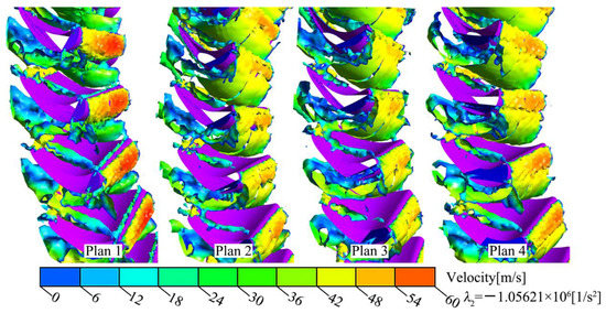
Figure 10.
Iso-surfaces of the λ2 criterion near the stator blade with different suppression slots (t = 0.12 s, SR = 0).
Figure 11 shows the distribution of velocity streamlines in the 0.5 span for different suppression slots. Compared with the flow field of the stator without slot structure, the flow field of the stator with the four slot designs has a high level of eddy flow, which is the reason for the decline in the hydrodynamic performance of the torque converter caused by the slot design. Plan 1 forms a high-speed jet in the slot, and a vortex flow is formed on both sides of the slot outlet. The flow velocity at the suction leading edge of the blade does not decrease to a great extent. For Plan 2, the slot outlet pressure is slightly lower than the inlet pressure, and the fluid is transported from the upstream of the blade through the slot to the downstream. The fluid flows at the inlet and outlet of the slot shear each other inside the slot to form a vortex flow inside the slot. For Plan 3, due to the increased slot width, the fluid inside the slot has a more obvious convection phenomenon, which will form a relatively large slot vortex structure. The fluid at the slot inlet flows to the downstream slot outlet, which is what causes the velocity vortex structure to sag near the leading edge of the blade. For Plans 2 and 3, the slot design will cause most of the vortex flow on the trailing edge of the blade and disturb the flow velocity in the mainstream area, thereby reducing the flow velocity and reducing the risk of cavitation. For Plan 4, the downstream of the blade suction side belongs to high-pressure fluid, and the upstream of the blade suction side belongs to low-pressure fluid due to the action of the high-speed fluid. The downstream fluid flows upstream through the slot, impinging on the high-velocity fluid in the mainstream area, causing the fluid to slow down and reducing the risk of cavitation. The fluid at the outlet of the slot will significantly reduce the fluid velocity in the mainstream area, causing more separation vortices in the downstream fluid, which is consistent with the velocity vortex structure distribution in Figure 10.
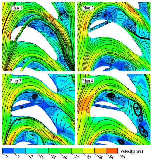
Figure 11.
Velocity distribution in stator domain under stall operating condition for various suppression slots (t = 0.12 s).
4. Discussion
4.1. Quantitative Analysis of Cavitation Threat with Slot Designs
The cavitation number is a dimensionless number that is essential for describing the threat of cavitation. The smaller the cavitation number, the greater the risk of cavitation. The equation is
In Equation (17), is the reference pressure, is the vapor pressure, is the fluid density, and is the reference velocity. In this study, the toroidal velocity is considered the reference velocity, and it is expressed as
where is the fluid mass flow rate and B is constant for a given design (in this case B = 2.56 × 10⁻² m2).
The hydrodynamic performance of the four suppression slots is calculated. The Tbg0 of Plan 4 deteriorates the most severely (6.81%). The K0 of Plan 4 is reduced the most (3.23%). Despite the hydrodynamic performance degradation, the application of suppression slots greatly suppresses the stator cavitation process in the HTC. Additionally, no unstable shedding cavitation is observed in the flow field of the HTC with the suppression slot blades, which can reduce noise and strong erosion caused by cavitation.
As seen in Figure 12, the cavitation number increases with SR, which indicates that low SRs lead to a high risk of cavitation. Additionally, the cavitation number of the baseline configuration is the smallest. After the slotted blade is used, the cavitation number can be greatly increased, and the cavitation threat around the blade is greatly decreased. The cavitation numbers of Plan 3 and Plan 4 are basically the same when SR ≤ 0.3, and they are also the blades with the most obvious increase in cavitation numbers. Plan 1 shows the worst improvement of the cavitation number, which means that its improvement effect of cavitation suppression is unsatisfactory.
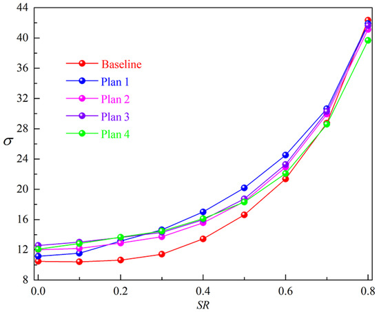
Figure 12.
Distribution of cavitation threat characteristics for various suppression slots.
The load distribution of the stator suction blade with the different suppression slots is shown in Figure 13. These findings are used to investigate the cavitation suppression effect of the different suppression slots under stall operating condition. The torque exerted by the fluid on the blade is identical to the integral of the product of the pressure on the blade and the radius. Therefore, it is directly identical to the pressure difference between the pressure surface and the suction surface of the blade. As shown in Figure 13, because of the accelerated flow of fluid near the leading edge of the stator suction surface, the pressure drop in this region is very noticeable, which is conducive to cavitation. When the baseline is near S0.1, the absolute pressure is close to 0, which means that the baseline configuration undergoes heavy cavitation. Additionally, the placement of the suppression slot increases the absolute pressure near the leading edge of the stator suction surface to varying degrees and reduces the cavitation effect in this region. The absolute pressure increase of Plan 4 is the most significant (the lowest absolute pressure is >3.0 × 10⁵ Pa), thus fully suppressing the stator cavitation. On the contrary, the method of slotting only the suction side (Plan 1) is not highly effective in suppressing the stator cavitation. Additionally, it causes the blade load to fluctuate drastically, which is not conducive to power transmission.
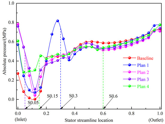
Figure 13.
Stator suction surface load distribution with different suppression slots under stall operating condition.
4.2. Effect of Slot Width
The influence of different slot widths on cavitation characteristics is shown in Figure 14. A larger slot width leads to a smaller cavitation volume in the stator. There is a strong linear relationship between the slot width and Tbg0, and there is a high-order functional relationship between the slot width and the cavitation volume in the stator. As for the slotting design between P0.1 and S0.3, when the slot width is 2 mm, the large cavitation volume of the stator means that the cavitation effect is still heavy. When the slot width reaches 3 mm, the cavitation volume of the stator is greatly reduced, and the cavitation effect is largely decreased. The slotting design is implemented between S0.05 and S0.4. The widening of the slot passage does not fully suppress the stator cavitation; in particular, the cavitation suppression effect is very limited. The slotting design is applied between S0.15 and S0.6, and the cavitation volume of the stator is greatly reduced as the slot widens. When the slot width reaches 2 mm, the stator cavitation is fully suppressed. Overall, the slot width plays a crucial role in suppressing the stator cavitation, especially in the slotting scheme of Plan 4.

Figure 14.
Effect of slot width on Tbg0 and stator vapor volume under different slot designs.
4.3. Effect of Slot Position
Figure 15 shows the suppression effect of the various slot positions on the stator cavitation. The slotting design from the pressure side to the suction side is studied, and the cavitation suppression effect of the stator at four different outlet positions is discussed. The findings indicate that the cavitation suppression effect is more obvious when the slot exit position is closer to the leading edge of the stator. The authors also discuss the cavitation suppression effect of the stator with slotted designs from the suction surface S0.15 to the suction surface at different positions. The results indicate that slotting at different suction surface positions can fully suppress the stator cavitation, and the suppression effect is almost the same. In general, the cavitation suppression effect of the stator designed with slots from the pressure surface to the suction surface is not as good as that of the stator with a slot on the suction surface. The slot position has a stronger effect on cavitation suppression than the slot width. The method of slotting the suction side has a better suppression effect on stator cavitation than the traditional method of slotting both sides of the pressure and suction sides. This slotting design technology is worthy of application in engineering.

Figure 15.
Effect of slot position on Tbg0 and stator vapor volume (slot width = 2 mm).
5. Conclusions
Transient simulation and hydrodynamic performance prediction of the three-dimensional cavitation flow field of an HTC are conducted and verified through experiments. To suppress the stator cavitation, we propose the use of two types of cavitation suppression slots (Plan 1 and Plans 2–4) in the blade profile design of the stator cascade. The suppression effects of slot width and slot position on the stator cavitation are investigated and compared. The following conclusions are drawn:
- (1)
- Simulation of the HTC cavitation flow field shows that cavitation mainly occurs in the leading edge of the suction side of the turbine and the stator, and the stator cavitation is severe. The mass flow rate of the torque converter at low SRs is very large. Hence, the suction side of the blade has a very low local pressure, which is the main reason that the cavitation of the torque converter mainly occurs at SR = 0, 0.1, 0.2, and 0.3. The stator cavitation is classified as unstable shedding cavitation, and there are periodic processes of cavitation inception, development, shedding, and collapse. The turbine cavitation is a stably attached cavitation.
- (2)
- According to the calculation and comparison of the cavitation flow field of the slotted stator, the method of slotting both the pressure and suction sides (Plan 1) is not as effective as the method of slotting the suction side (Plans 2–4) in suppressing the stator cavitation. The slot width and slot position play an essential role in the suppression of the stator cavitation. First, the most effective slot position lies between S0.15 and S0.6 on the stator blade suction side, and the stator cavitation can be suppressed completely. Second, when the slot width reaches 2 mm, the stator cavitation can be fully suppressed. However, the suppression effect of the slot width on the stator cavitation is not as good as the suppression effect of the slot position.
- (3)
- As for the method of slotting both the pressure and suction sides, when the position of the slot entrance (blade pressure side) is fixed, the closer the slot exit (blade suction side) to the leading edge of the blade suction side, the better the cavitation suppression effect of the stator. For the method of slotting one side of the suction side, when the position of the slot exit (blade suction side) is fixed (S0.15), the position of the slot entrance (blade suction side) has the same effect on the cavitation suppression of the stator, which can almost completely suppress the stator cavitation. The larger the slot width, the better the cavitation suppression effect of the stator, but it will severely compromise the hydrodynamic performance of the torque converter. Ideally, the slot width should not exceed 2 mm.
The slotted stator blades will seriously affect the hydrodynamic performance of a torque converter. Braibant and Fleury proposed that the parametric design and sensitivity analysis of a geometric contour curve with a B-spline can effectively improve the smoothness and design efficiency of the curve [29]. Poles et al. verified the influence of the initial population sampling on the convergence of advanced optimization algorithms such as MOGA-II and NSGA-II and concluded that a reasonable distribution of the initial population sampling can speed up the convergence of the optimization algorithm [30]. In addition, the Kriging model has prominent advantages in constructing the surrogate model with multiple independent variables and objective functions. Mariotti et al. optimized the diffuser’s contoured cavities using Bezier curves to maximize pressure recovery and minimize flow separation, thereby achieving key hydrodynamic performance indicators such as improving diffuser efficiency [31,32].
Therefore, the authors intend to combine the NURBS curve (Bezier curve is a special case of NURBS curve) and an advanced optimization algorithm to carry out multiobjective optimization of the key geometric parameters of the stator slots and blade profile design of a torque converter in future research. This method can improve the cavitation resistance and hydrodynamic performance of a torque converter, which can provide a new reference for the researchers of fluid machinery.
Author Contributions
Z.R. performed the data analyses, designed and performed the experiments, and wrote the manuscript; C.L. contributed significantly to analysis and manuscript preparation; C.L. and W.M. contributed to the conception of the study; C.L. helped perform the analysis with constructive discussions. All authors have read and agreed to the published version of the manuscript.
Funding
This work has been founded by the National Natural Science Foundation of China (Grant No. 52075212) and the Natural Science Foundation of Jilin Province (Grant No. 20200201222JC).
Institutional Review Board Statement
Not applicable.
Informed Consent Statement
Not applicable.
Data Availability Statement
The data presented in the study are available on request from the corresponding author.
Conflicts of Interest
The authors declare that they have no conflict of interest.
Nomenclature
| Nuclei volume fraction | |
| Vapor volume fraction | |
| Vapor density (kg/m3) | |
| Vapor viscosity (Pa s) | |
| Liquid oil density (kg/m3) | |
| Liquid oil viscosity (Pa s) | |
| Cavitation vapor bubble radius (m) | |
| Vapor pressure (Pa) | |
| Liquid pressure (Pa) | |
| Interphase mass transfer per unit (kg/s) | |
| The bubble density number | |
| Cavitation vaporization coefficient | |
| Cavitation condensation coefficient | |
| Revolution speed of pump (r/s) | |
| Number of the pump | |
| t | Time (s) |
| Speed ratio | |
| Torque ratio | |
| Capacity factor/ | |
| Efficiency | |
| Pump rotational speed (rpm) | |
| Turbine rotational speed (rpm) | |
| The torque of the pump (Nm) | |
| The torque of the turbine (Nm) | |
| W | Width of the suppression slot (mm) |
| U | Velocity component of direction x (m/s) |
| V | Velocity component of direction y (m/s) |
| W | Velocity component of direction z (m/s) |
| Reference pressure (Pa) | |
| Reference velocity (m/s) | |
| The toroidal velocity (m/s) | |
| Test | Test data |
| NOC | Noncavitation CFD results |
| Cavi | Cavitation CFD results |
References
- Moshfeghi, M.; Shams, S.; Hur, N. Aerodynamic performance enhancement analysis of horizontal axis wind turbines using a passive flow control method via split blade. J. Wind Eng. Ind. Aerodyn. 2017, 167, 148–159. [Google Scholar] [CrossRef]
- Shin, S.; Lee, B.-C.; Hong, J.-H.; Joo, I.-S. Performance Improvement Using a Slotted Stator of an Automotive Torque Converter. In Proceedings of the 2003 SAE World Congress, Detroit, Michigan, 3–6 March 2003; Volume 1, p. 2047. [Google Scholar] [CrossRef]
- Wu, G.; Wang, L. Application of dual-blade stator to low-speed ratio performance improvement of torque converters. Chin. J. Mech. Eng. 2016, 29, 293–300. [Google Scholar] [CrossRef]
- Ni, Z.; Dhanak, M.; Su, T.-C. Improved performance of a slotted blade using a novel slot design. J. Wind Eng. Ind. Aerodyn. 2019, 189, 34–44. [Google Scholar] [CrossRef]
- Ni, Z.; Dhanak, M.; Su, T.-C. Performance Characteristics of Airfoils with Leading-Edge Tubercles and an Internal Slot. AIAA J. 2019, 57, 2394–2407. [Google Scholar] [CrossRef]
- Belamadi, R.; Djemili, A.; Ilinca, A.; Mdouki, R. Aerodynamic performance analysis of slotted airfoils for application to wind turbine blades. J. Wind Eng. Ind. Aerodyn. 2016, 151, 79–99. [Google Scholar] [CrossRef]
- Liu, C.; Yang, K.; Li, J.; Xu, Z.; Wang, T. Performance improvement and flow field investigation in hydraulic torque converter based on a new design of segmented blades. Proc. Inst. Mech. Eng. Part D J. Automob. Eng. 2020, 234, 2162–2175. [Google Scholar] [CrossRef]
- Amromin, E. Design approach for cavitation tolerant hydrofoils and blades. J. Fluids Struct. 2014, 45, 96–106. [Google Scholar] [CrossRef]
- Timoshevskiy, M.; Zapryagaev, I.; Pervunin, K.; Markovich, D.M. Cavitation control on a 2D hydrofoil through a continuous tangential injection of liquid: Experimental study. In AIP Conference Proceedings; AIP Publishing LLC: New York, NY, USA, 2016; Volume 1770, p. 030026. [Google Scholar] [CrossRef]
- Kawanami, Y.; Kato, H.; Yamaguchi, H.; Tanimura, M.; Tagaya, Y. Mechanism and Control of Cloud Cavitation. J. Fluids Eng. 1997, 119, 788–794. [Google Scholar] [CrossRef]
- Javadi, K.; Dorostkar, M.M.; Katal, A. Cavitation passive control on immersed bodies. J. Mar. Sci. Appl. 2017, 16, 33–41. [Google Scholar] [CrossRef]
- Liu, C.; Wei, W.; Yan, Q.; Weaver, B.K. Torque Converter Capacity Improvement through Cavitation Control by Design. J. Fluids Eng. 2017, 139, 041103. [Google Scholar] [CrossRef]
- Liu, C.; Wei, W.; Yan, Q.; Weaver, B.K.; Wood, H.G. Influence of Stator Blade Geometry on Torque Converter Cavitation. J. Fluids Eng. 2018, 140, 041102. [Google Scholar] [CrossRef]
- Liu, C.; Yan, Q.; Wood, H.G. Numerical investigation of passive cavitation control using a slot on a three-dimensional hydrofoil. Int. J. Numer. Methods Heat Fluid Flow 2020, 30, 3585–3605. [Google Scholar] [CrossRef]
- Choi, Y.-D.; Kurokawa, J.; Imamura, H. Suppression of Cavitation in Inducers by J-Grooves. J. Fluids Eng. 2007, 129, 15–22. [Google Scholar] [CrossRef]
- Park, S.; Lee, S.; You, G.; Suh, J.C. An experimental study on tip vortex cavitation suppression in a marine propeller. J. Ship. Res. 2014, 58, 157–167. [Google Scholar] [CrossRef]
- Zwart, P.; Gerber, A.G.; Belamri, T. A two-phase flow model for predicting cavitation dynamics. In Proceedings of the ICMF 2004 International Conference on Multiphase Flow, Yokohama, Japan, 30 May–4 June 2004; pp. 1–11. [Google Scholar]
- Liu, C.; Guo, M.; Yan, Q.D.; Wei, W. Numerical Investigation on the Transient Cavitating Flow inside a Torque Converter. In Proceedings of the IEEE 8th International Conference on Fluid Power and Mechatronics (FPM), Wuhan, China, 10–13 April 2019; pp. 208–216. [Google Scholar]
- Geng, L.; Escaler, X. Assessment of RANS turbulence models and Zwart cavitation model empirical coefficients for the simulation of unsteady cloud cavitation. Eng. Appl. Comput. Fluid Mech. 2020, 14, 151–167. [Google Scholar] [CrossRef]
- Long, X.; Cheng, H.; Ji, B.; Arndt, R.E.; Peng, X. Large eddy simulation and Euler–Lagrangian coupling investigation of the transient cavitating turbulent flow around a twisted hydrofoil. Int. J. Multiph. Flow 2018, 100, 41–56. [Google Scholar] [CrossRef]
- Guo, M.; Liu, C.; Yan, Q.; Ke, Z.; Wei, W.; Li, J. Evaluation and Validation of Viscous Oil Cavitation Model Used in Torque Converter. Appl. Sci. 2021, 11, 3643. [Google Scholar] [CrossRef]
- Schulz, H.; Greim, R.; Volgmann, W. Calculation of Three-Dimensional Viscous Flow in Hydrodynamic Torque Converters. J. Turbomach. 1996, 118, 578–589. [Google Scholar] [CrossRef]
- Liu, C.; Untaroiu, A.; Wood, H.G.; Yan, Q.; Wei, W. Parametric Analysis and Optimization of Inlet Deflection Angle in Torque Converters. J. Fluids Eng. 2015, 137, 031101. [Google Scholar] [CrossRef]
- Liu, C. Study on Parameterized Cascade Design of Radial-Turbine Torque Converter. Ph.D. Thesis, Beijing Institute of Technology, Beijing, China, 2015. [Google Scholar]
- Liu, C.B.; Liu, C.S.; Ma, W.X. Mathematical model for elliptic torus of automotive torque converter and fundamental analysis of its effect on performance. Math. Probl. Eng. 2015, 2015, 851816. [Google Scholar] [CrossRef]
- Yang, K.; Liu, C.; Li, J.; Xiong, J. Calculation and analysis of thermal flow field in hydrodynamic torque converter with a new developed stress-blended eddy simulation. Int. J. Numer. Methods Heat Fluid Flow 2021, 31, 3436–3460. [Google Scholar] [CrossRef]
- Jeong, J.; Hussain, F. On the identification of a vortex. J. Fluid Mech. 1995, 285, 69–94. [Google Scholar] [CrossRef]
- Mariotti, A.; Buresti, G.; Salvetti, M. Separation delay through contoured transverse grooves on a 2D boat-tailed bluff body: Effects on drag reduction and wake flow features. Eur. J. Mech. B/Fluids 2019, 74, 351–362. [Google Scholar] [CrossRef]
- Braibant, V.; Fleury, C. Shape optimal design using B-splines. Comput. Methods Appl. Mech. Eng. 1984, 44, 247–267. [Google Scholar] [CrossRef]
- Poles, S.; Fu, Y.; Rigoni, E. The effect of initial population sampling on the convergence of multi-objective genetic algorithms. In Multiobjective Programming and Goal Programming; Barichard, V., Gandibleux, X., T’Kindt, V., Eds.; Springer: Berlin/Heidelberg, Germany, 2009; pp. 123–133. [Google Scholar]
- Mariotti, A.; Buresti, G.; Salvetti, M. Control of the turbulent flow in a plane diffuser through optimized contoured cavities. Eur. J. Mech. B/Fluids 2014, 48, 254–265. [Google Scholar] [CrossRef]
- Mariotti, A.; Buresti, G.; Salvetti, M. Use of multiple local recirculations to increase the efficiency in diffusers. Eur. J. Mech. B/Fluids 2015, 50, 27–37. [Google Scholar] [CrossRef]
Publisher’s Note: MDPI stays neutral with regard to jurisdictional claims in published maps and institutional affiliations. |
© 2022 by the authors. Licensee MDPI, Basel, Switzerland. This article is an open access article distributed under the terms and conditions of the Creative Commons Attribution (CC BY) license (https://creativecommons.org/licenses/by/4.0/).