Abstract
The focused infrared (IR) heating method is an energy-efficient heating technology for engineering applications. Numerical models of focused IR heating technology have been introduced based on the theory of ray optics. The ray optics-based IR models have provided good simulation results; however, they are mathematically complex because the ray optics models need to account for the complex paths of the IR rays and the geometrical information of the heating devices. This paper presents a new approach for modeling the focused IR heating method using quantum mechanical formulations. Even though the IR heating condition is not a pure quantum phenomenon, it is efficient to employ the concept of the superposition principle of wave functions in IR distribution modeling. The proposed model makes an abstraction by replacing the distributed IR rays with an energy particle with independent wave functions at different eigenstates, based on the Schrödinger equation. The new approach results in a simpler equation for modeling the focused IR heating method. An electrical-thermal simulation of the focused IR heating with the new model provides results in good agreement with the experimental data.
1. Introduction
The focused infrared (IR) heating method has been widely used in engineering applications because of its low cost and excellent energy efficiency; it has been used in cooking [1,2,3,4], medical devices [5], drying [6,7], and in the metal forming fields [8,9]. IR consists of electromagnetic waves with wavelengths between 0.78 and 1000 μm [2]. When IR rays reach the surface of a material, some of the IR rays are absorbed inside the material. The absorbed IR energy activates the molecules of the material, increasing the temperature of the material, as explained in [3]. This radiant heating is highly preferred in the food industry because it has a sterilizing effect as well as a heating effect [10]. An IR heater mainly consists of an IR lamp and a reflector, and various types of heating can be created according to the design of the reflector, as shown in [11]. One of the most widely used types of reflector is the elliptical-shaped reflector because it can concentrate IR energy in a very narrow area to increase the energy efficiency [10,11]. While an elliptical reflector theoretically collects all of the IR energy emitted from the IR lamp to the target focus, diffusion reflection and shape errors distribute the IR heat flux out of the target point [12,13]. The food industry has introduced some models to optimize the process of using IR for drying [14], baking [15,16], roasting [17], and thawing [18]. In the modeling of food processing, more attention is paid to mass transfer due to moisture rather than IR flux distribution [10]. In the case of soldering and metal heat treatment, the IR distribution is an important issue for process optimization because there is no mass change and heating should be completed quickly [10]. Sun et al. [19] and Dong et al. [20] conducted optimal design and measurement of the collected energy generated by elliptical reflectors for engineering applications. Lee et al. [21,22] introduced numerical models of the IR distribution for fast heat treatment processes of metal sheets. Kim et al. [23] recently conducted an optimization of the heat-assisted mechanical trimming process based on IR distribution modeling. Even though the aforementioned models have shown good results, they are mathematically complex because they are strongly affected by the complex paths of the IR rays and the geometric information of the elliptical reflector [16].
This paper presents a new approach for modeling the focused IR heating method by using quantum mechanical formulations. Even though the IR heating condition is not a pure quantum mechanical phenomenon, it is efficient to employ the superposition principle of wave functions in modeling the IR distribution [24]. The wave function can be obtained by solving the Schrödinger equation, which is a differential equation describing the quantum mechanical system. The Schrödinger equation [25] was introduced in 1926, inspired by the de Broglie’s matter wave hypothesis [26,27]. Schrödinger mathematically defined the wave function for a single electron-proton system of hydrogen atoms, and this equation has been commonly used in quantum mechanics. By integrating the wave functions for the spatial domain, the probability of finding particles in a specific time and space can be obtained in the quantum mechanics [28]. Because of this characteristic, the Schrödinger equation has been widely used in engineering problems that require solving probability density [29,30,31]. This work also uses this characteristic in the IR heating analysis.
In this work, the focused IR heating condition is replaced with an infinite potential well problem of quantum mechanics. In this case, the entrance of the reflector is considered as the potential well for the IR energy, and the distributed IR energy is modeled by an energy particle having wave functions of independent eigenstates, based on the Schrödinger equation [32]. This paper shows that the abstraction can build a much simpler formulation for the distributed IR energy in the focused IR heating method because it does not trace all the paths of the IR rays. In addition, the new model is implemented into a multiphysics simulation code, COMSOL, using the weak forms derived to consider electrical-thermal phenomena. A multiphysics analysis is conducted to simulate the focused IR heating for a metal sheet, demonstrating that the model is in good agreement with the experimental data.
2. Modeling
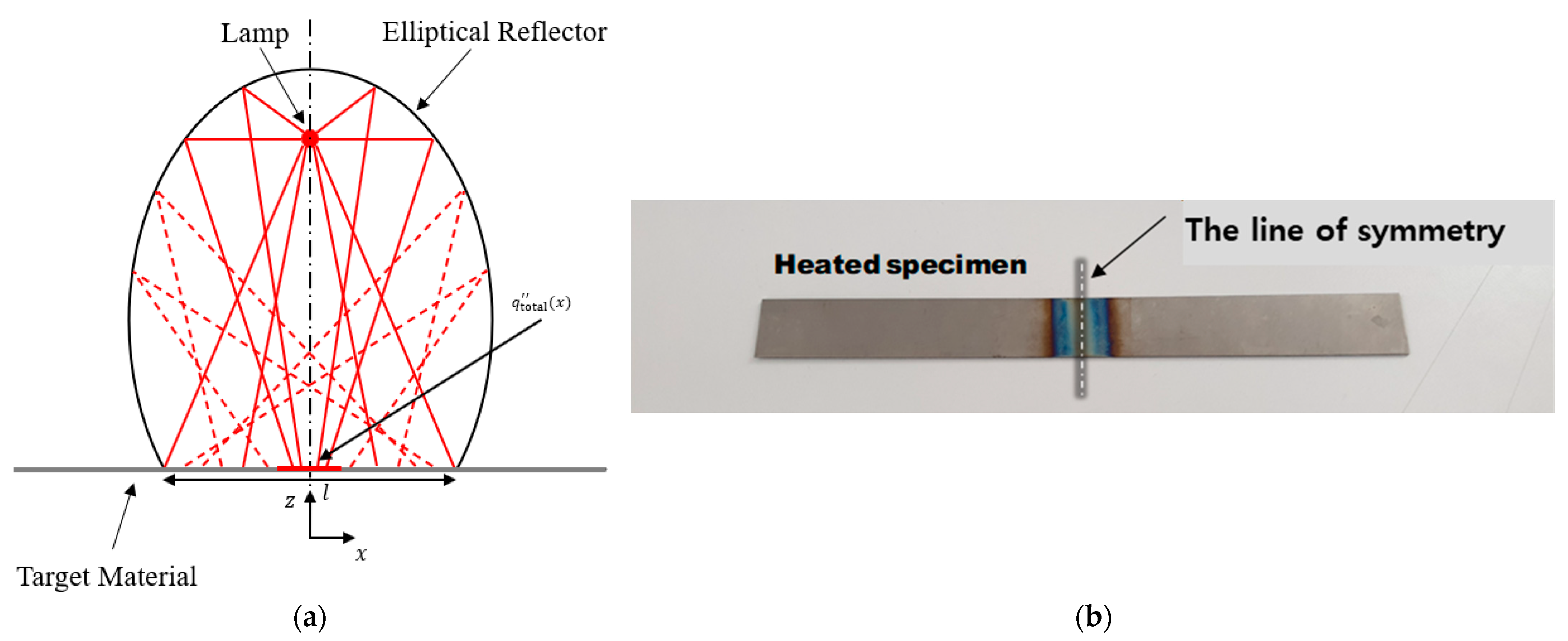
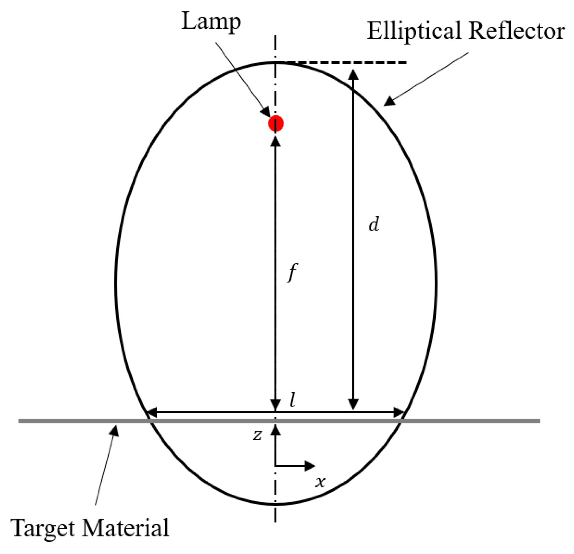
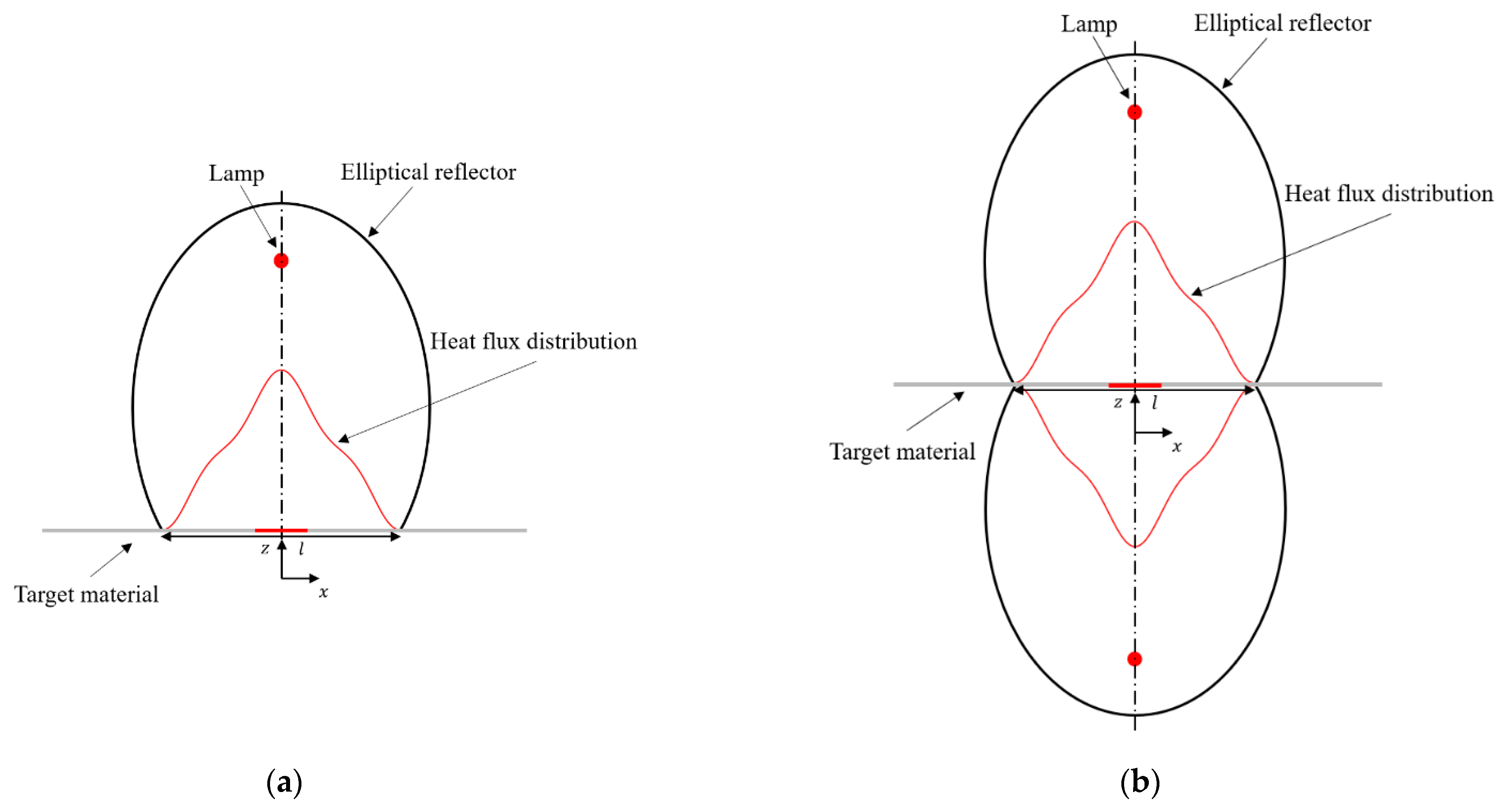
2.1. Focused IR Heating Condition
Figure 1 presents a conceptual drawing of the focused IR heating method. As shown in Figure 1a, the lamp and target material are located at each focal point of the elliptical reflector; the reflector can gather a large portion of the emitted IR energy within a narrow area. is the IR energy distribution in the heated area and denotes the entrance length of the elliptical reflector. There have been some numerical studies on modeling [19,20,21,22]. The reported models differ slightly in detail but share the fundamental point of being based on the theory of ray optics; the models trace all paths of the IR rays emitted from the lamp in geometric ways, including reflector reflections. Figure 1b shows an example of the focused heating effect in a metal sheet; the heated example is from [22]. As the cross-sectional shapes of the lamp and elliptical reflector are uniform in the longitudinal direction, it is efficient to assume that the gradient of the heat flux distribution in the longitudinal direction is negligible, which allows in-plane modeling, as presented in Figure 1a. In the ray optics-based models in [19,20,21,22], the equations are mathematically complex; calibration is not easy because the IR rays travel through highly complex paths caused by reflections. This study aimed to build a simpler and more accurate model in the aspect of energy, which is a scalar quantity.
Figure 1.
Focused IR heating method: (a) Illustration of the focused IR heating; (b) Example of a specimen heated by the IR heating [22].
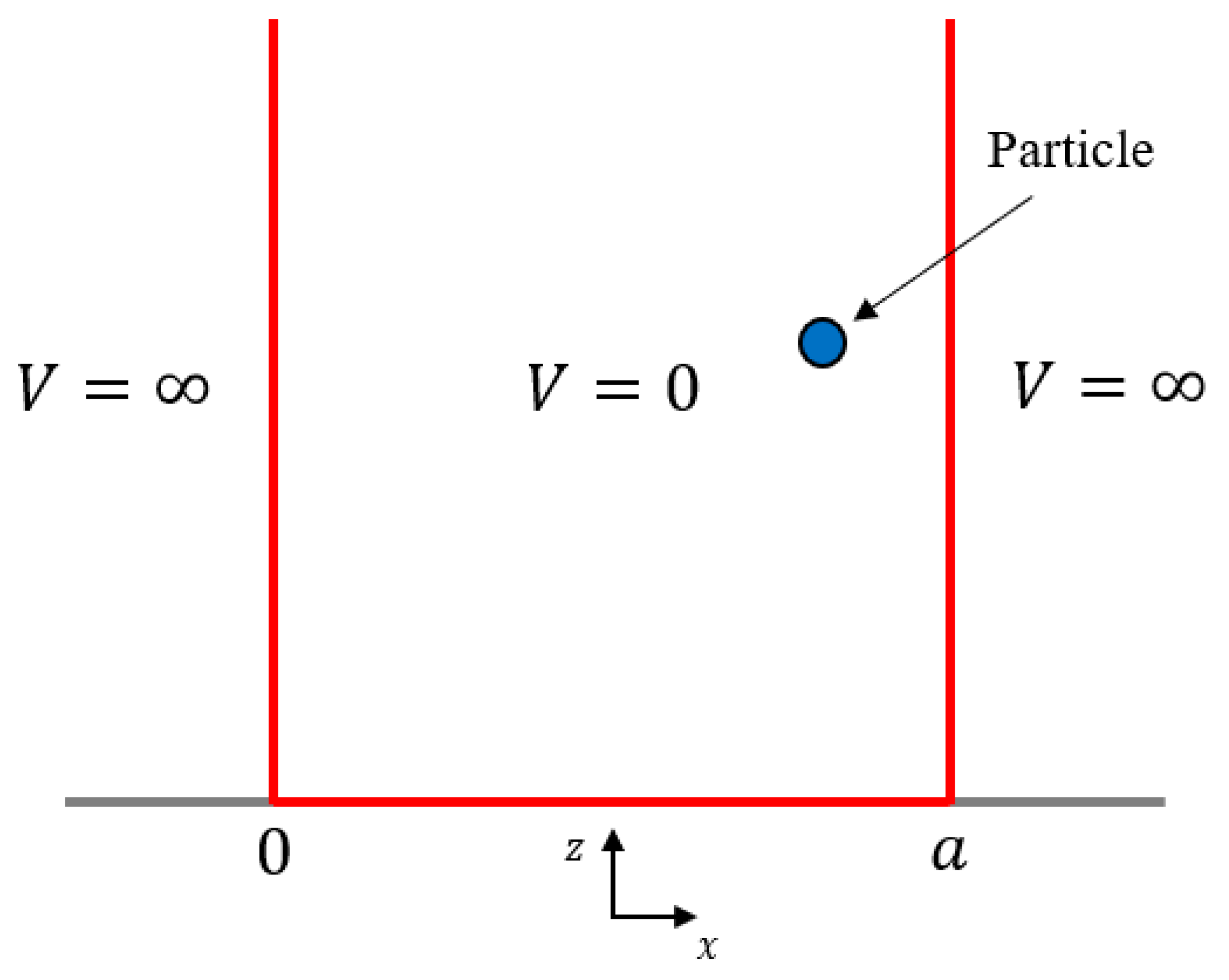
2.2. New Model Based on Quantum Mechanical Formulation
This section proposes a new numerical model of the IR distribution based on the Schrödinger equation. An IR lamp was combined with an elliptical reflector, as shown in Figure 2; , , and denote the focal length of the ellipse, entrance length of the reflector, and the height between the target material and top of the ellipse, respectively. In this case, the IR rays are distributed over the entrance length . This work replaces this condition with the one-dimensional infinite potential well problem, where an imaginary energy particle is located probabilistically [33]. As the heat flux from the lamp does not depend on time, the time-independent Schrödinger equation can be used:
is the mass of the particle, is the energy, represents the reduced Planck’s constant, and denotes the wave function. In this analogy, the energy particles are imaginary.
Figure 2.
Geometrical parameter of the elliptical reflector.
Figure 3 presents the concept drawing of the energy particle in the infinite potential well. The particle cannot exist outside the well; therefore, the boundary condition is given by:
where is the length of the infinite potential well. The solution of is well-known [33], given by:
Figure 3.
Infinite potential well.
By applying the boundary condition of Equation (2) to Equation (3), the value of becomes for , while for . This leads to . By applying the parameter to Equation (3), the wave function at the eigenstate is determined by:
should satisfy the below probability density condition and orthogonal conditions, respectively.
As is a time-independent function in the IR heating condition, . Combining Equations (4) and (5) determines the value of , then the wave function of the eigenmode is represented by:
where because the length of the reflector and the length of the potential well are the same in this study. Then the energy of the eigenmode is determined simply by:
Next, an arbitrary state of the wave function can be given by the superposition of several eigenmode functions, as follows:
The coefficients, , should satisfy the below condition:
The value of each eigenmode in Equation (9) represents the coefficient of each . Then, the energy distribution can be given by:
By using Equation (10), the IR distribution, , of Figure 1a can be simply modeled as below:
Note that is the magnitude of the heat flux incident in the opposite direction of the outward unit normal vector of the heated surface. To use the model in engineering applications, and should be specified using a model calibration process. For the calibration, the integration of the should be the same as the power of the lamp . Note that as the cross-section of the IR lamp is constant, is given by the total power per filament length. The quantum mechanical formulation provides:
where:
denotes the eigenvectors of the eigenmode, and the adjoint operator can take the transposed tensor in the time-independent wave functions. Equations (11) and (12) provide simple modeling of the focused IR heating because it does not trace all paths of the IR rays.
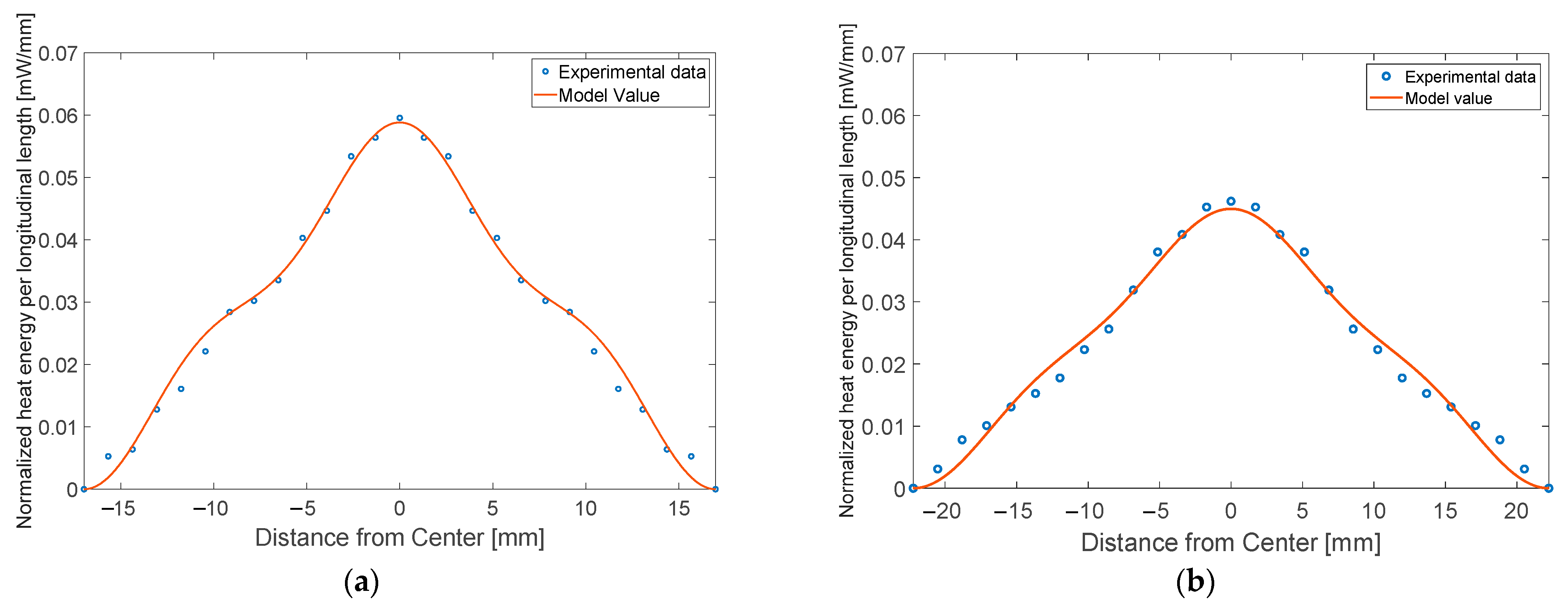
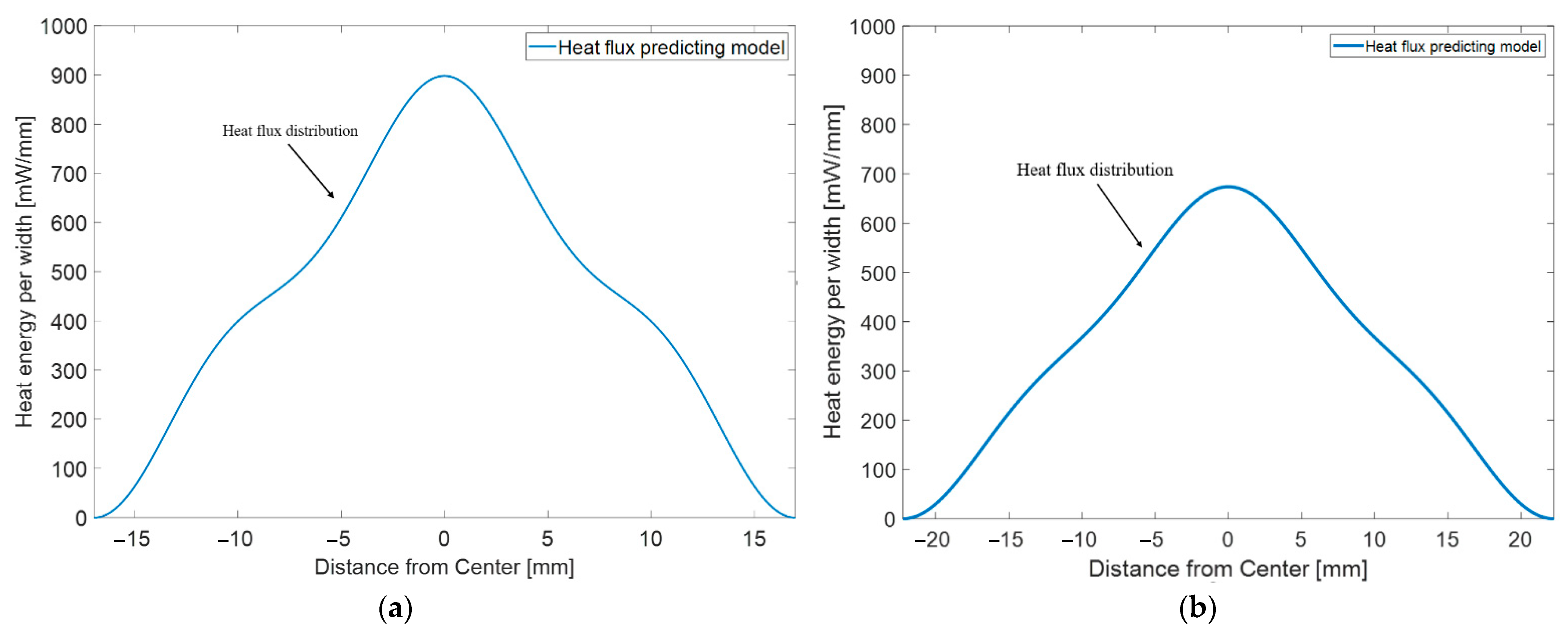
2.3. Model Calibration
This section describes the calibration of the proposed model. The basic idea is to make the form of match the distribution of IR rays. In this case, an IR power meter can be used to capture the heat flux of an IR heater. The IR distribution data can be obtained by measuring the IR intensity from the center to the end of the entrance length at different positions. The used IR power meter and details of the heat flux measurement process are described in Appendix A. The measured data were normalized using the lamp power. For the calibration, it is convenient to define a normalized energy distribution probability and normalizing coefficient .
where:
Equation (13) sets the mass of the imaginary energy particle to be , then becomes:
The normalizing coefficient, , is used to calibrate the model. Because is normalized by the total energy flux of the lamp , the probability distribution condition is represented as below:
can be calibrated by the normalized measured data using the least square method [34], and the calibrated values of and for focal length 20 mm and 40 mm cases are summarized in Table 1. In this work, the 1st, 2nd, and 3rd eigenmodes were used because it was confirmed that using the three modes is sufficient to capture the data well in the calibration. In Figure 4a,b, the normalized measurement data and calibrated models for the focal length of 20 mm and 40 mm are presented; the model follows the IR distribution well. The 20 mm focal length (Figure 4a) results in a narrower concentration of energy than the 40 mm focal length case (Figure 4b). Details are discussed in the discussion section. From the calibrated in Figure 4, the total heat flux distribution, , can be obtained by considering based on Equation (12) for each focal length. The total heat flux distributions, , for the focal lengths of 20 mm and 40 mm are shown in Figure 5a,b, respectively. in Equations (10) and (11) can be implemented into a FEM code for electrical-thermal simulations of the focused IR heating conditions.
Table 1.
Calibration of the model for the IR heater.
Figure 4.
Calibration of the new model: (a) Focal length 20 mm; (b) Focal length 40 mm.
Figure 5.
Modeling of the IR energy distribution: (a) Focal length 20 mm; (b) Focal length 40 mm.
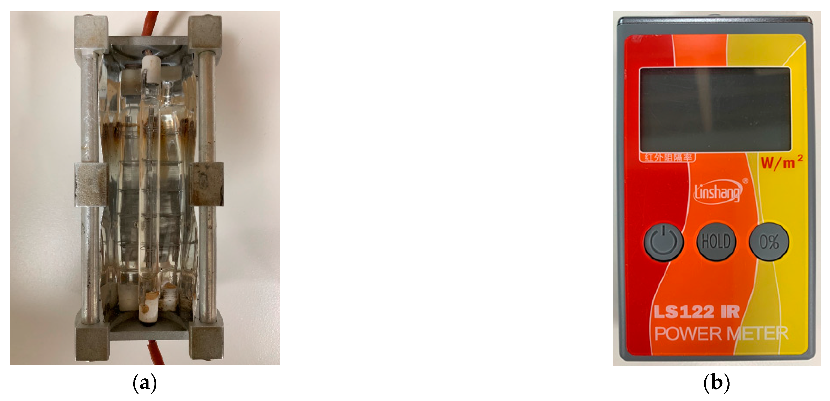
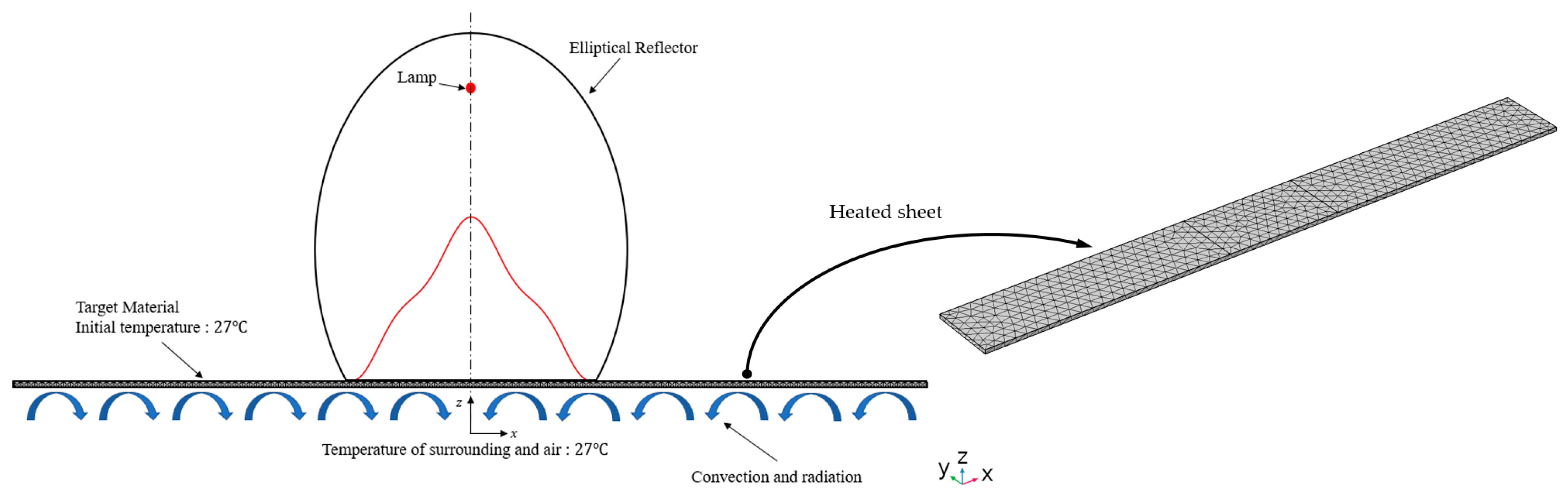
3. FEM Simulation and Experimental Validation
3.1. Electrical-Thermal Balance Equations for the FEM Simulation
This section presents the implementation of the model into the FEM code. The IR lamp converts electrical energy into IR radiation energy using the tungsten filaments inside the lamp. During the energy conversion, the filament temperature increases to – and the radiant heat energy was emitted into the surrounding space; the lamp should satisfy the electrical–thermal energy balance. First, the conservation of energy charge [35] is considered:
is the electric current, is the electrical conductivity, and is the electrical potential. A weak form for the FEM can be derived as below:
where is the volume integral term and represents the surface integral term. is the outward unit vector normal to the surface and is the shape function of the FEM, , which denotes an external force as the boundary condition of the electrical potential. By solving Equation (17), the electrical current vector, , can be obtained by substituting into Joule’s law [36], leading to thermal energy conversion:
is the electrical resistance of the filament and is the time rate of the thermal energy converted from electrical energy. The thermal balance [37] of the lamp was considered:
where is the thermal conductivity, is the density, is the thermal capacity, and is the absolute temperature. A weak form of Equation (19) can be derived under static condition () as follows:
includes the energy loss through convection and radiation to the surrounding air; is the heat convection coefficient, is the ambient temperature, is the Stefan–Boltzmann constant, and denotes the emissivity of the filament. The radiation energy is considered as the IR energy emitted from the lamp. By solving the electrical–thermal energy balance of the lamp in Equation (20), the emitted IR power, , was calculated; can be converted to the IR distribution using Equation (12). Next, the material heated by the IR energy should be modeled. The heated material is based on the same thermal balance in Equation (19). The differences are that the heated material considers a transient state () and IR heating condition (). The thermal balance of the material [38] is given by:
denotes the IR energy distribution, modeled using Equation (11). The target heated material in this study was a dual-phase (DP) 980 steel sheet. The numerical equations were implemented in the COMSOL Multiphysics program through the weak form of the partial differential equation mode.
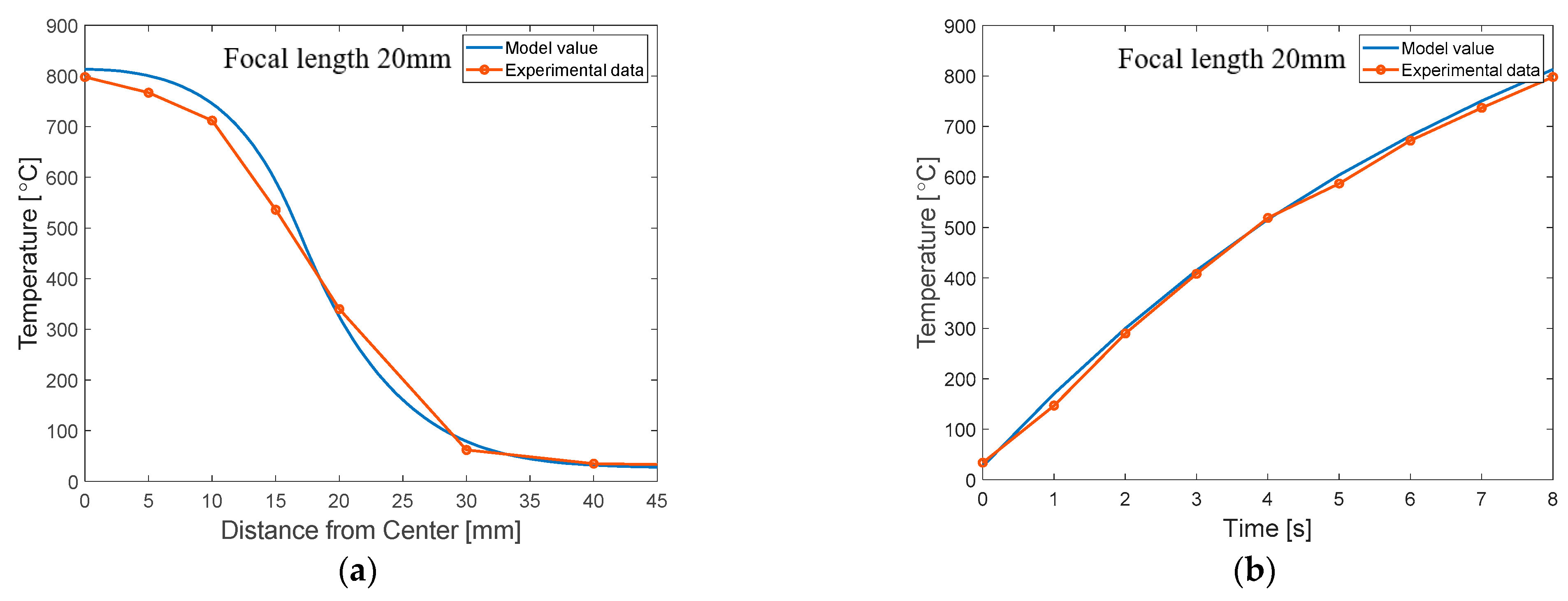
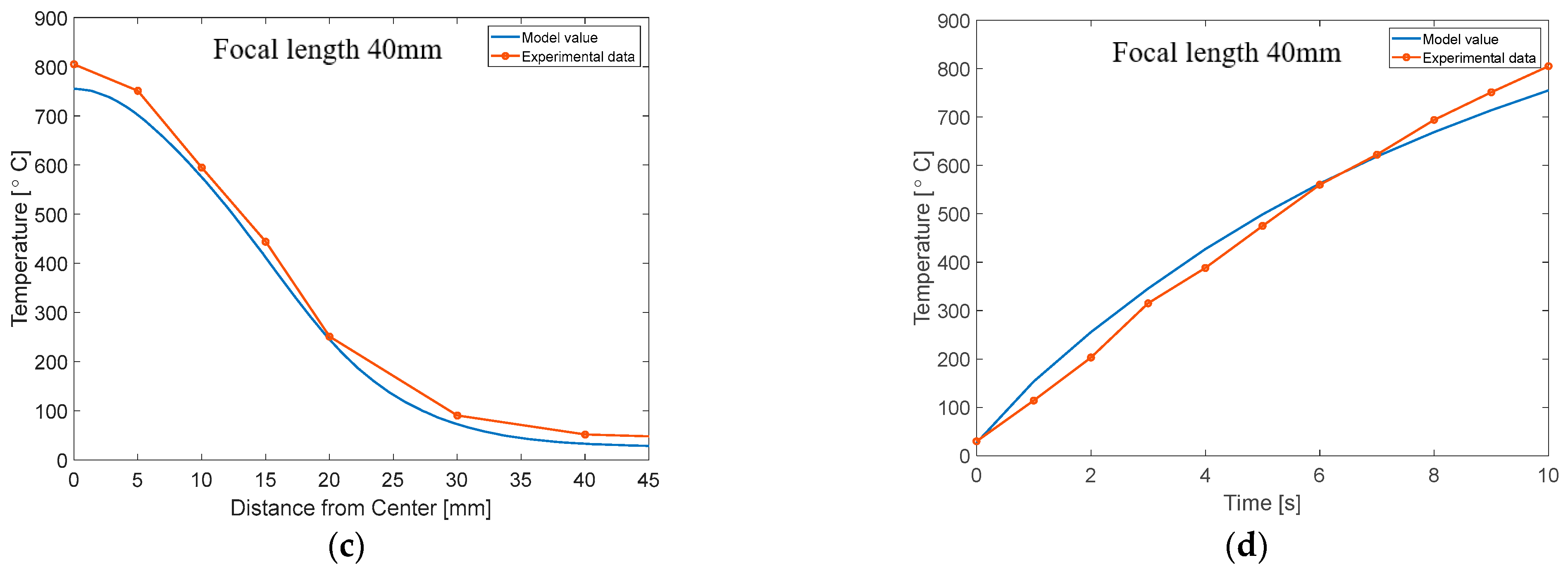
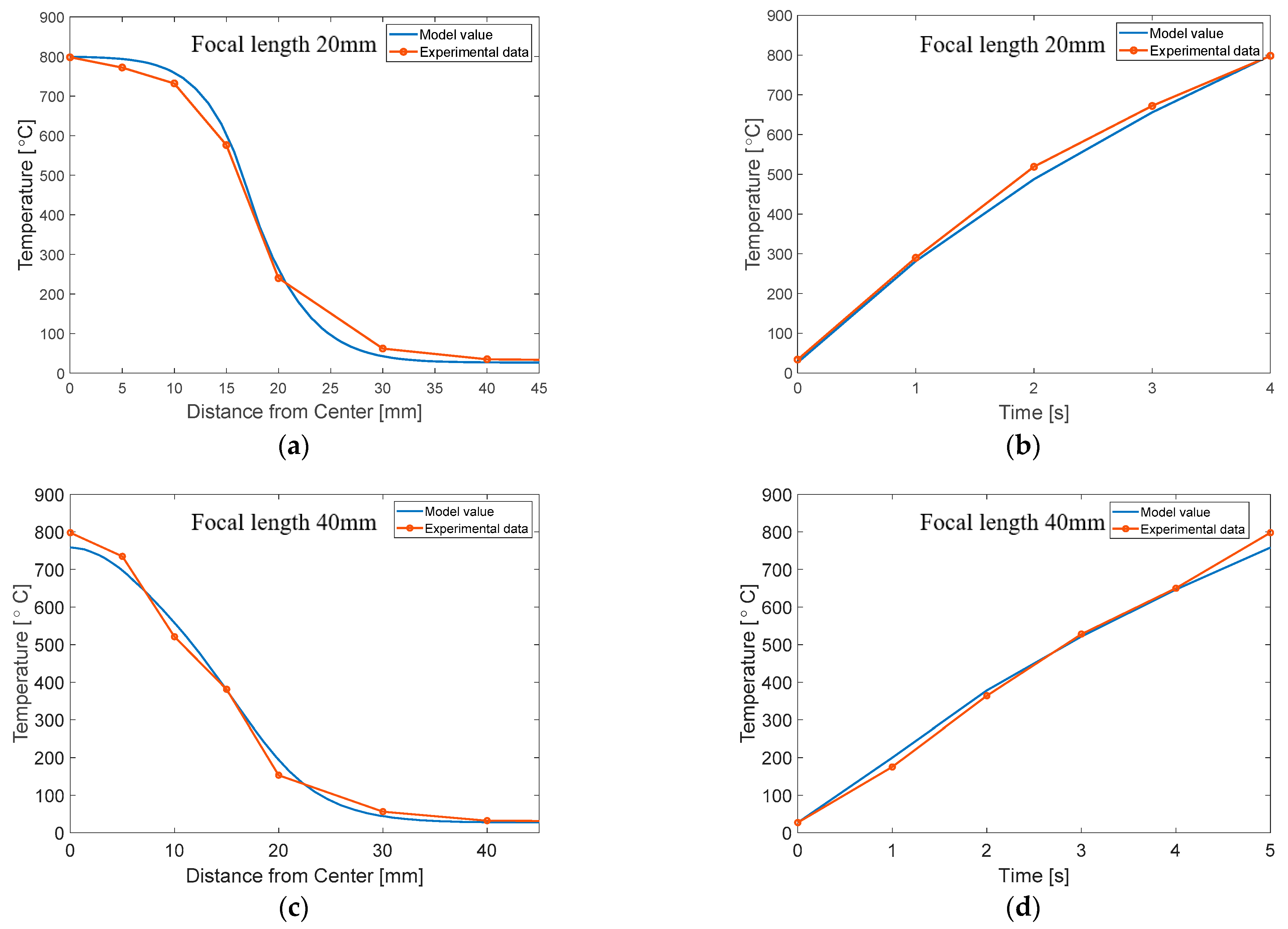
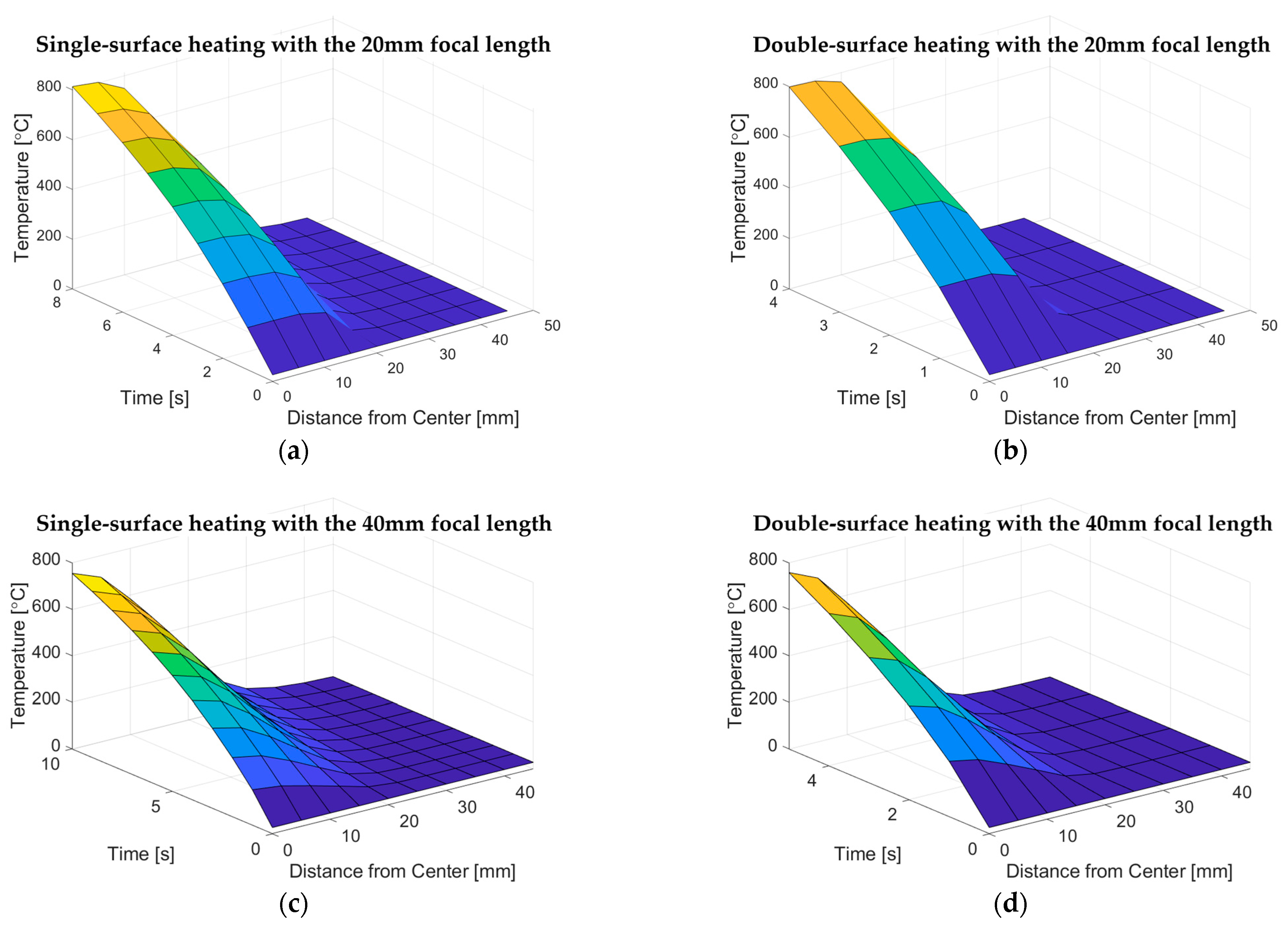
3.2. Results of the FEM Simulation and Validation
This section demonstrates the validation of the model with the experimental data, which are obtained from [21]. The experimental results include two heating conditions: single-surface and double-surface heating conditions, as shown in Figure 6a,b, respectively. The heated specimen had dimensions of . In this experiment, the DP 980 sheets were heated until the center of the heated area reached . Figure 7 presents the FE modeling of the focused IR heating conditions. The temperatures of the air and initial material were assumed as (). Note that the heating simulations were conducted based on the absolute temperature unit (K). The degree Celsius unit (°C) was used only to compare the simulation results to the experimental results. The heated sheet was modeled using the linear tetrahedron element based on the dimensions of the test specimen, as shown in Figure 7. The convective heat transfer coefficient of air was applied, and the emissivity of the material was . In the FE simulation, the electric-thermal analysis of the lamp was first conducted to obtain with the model parameters listed in Table 2. was calculated as 1777 W, and the transient simulation of the IR heating was conducted with the material properties of DP 980 in Table 3. The values for material properties are consistent with the values in [21,39]. In the simulation of IR heating, the values in Table 1 were used for the parameters of the new model according to the focal length of the reflector.
Figure 6.
Illustration of two heating cases: (a) Single-surface heating; (b) Double-surface heating.
Figure 7.
FEM modeling and heating condition.
Table 2.
Parameters of the IR lamp.
Table 3.
Properties of the heated material.
Figure 8 and Figure 9 show the simulation results of the single and double-surface heating conditions, respectively. Figure 8a and Figure 9a present the temperature distribution for the 20 mm focal length case when the central temperature reaches , in the single and double-surface heating conditions, respectively. Figure 8b and Figure 9b show the heating rate at the heating center for each heating method in the 20 mm focal length; the double-surface heating method (Figure 9b) provides much faster heating than the single-surface heating condition (Figure 8b). Figure 8c,d present the temperature distribution and heating rate, respectively, of the 40 mm focal length method in the single-surface heating condition. By comparing Figure 8b,d, it can be seen that the reflector with the 20 mm focal length provides a faster heating rate to reach the same temperature compared to the 40 mm focal length because the 20 mm focal length reflector focuses more energy on the center, as shown in Figure 4 and Figure 5. Figure 9c,d shows the temperature distribution and heating rate, respectively, in the double-surface heating with the 40 mm focal length. The simulation predicts the experimental results well. The multiphysics simulation results with the new model agree well with the measured data in Figure 8 and Figure 9. Figure 10 presents the simulated temperature surfaces with respect to the position in the heated area and heating time. Figure 10a–d present the temperature surfaces of the single-surface heating for the 20 mm focal length, double-surface heating for the 20 mm focal length, single-surface heating for the 40 mm focal length, and double-surface heating for the 40 mm focal length, respectively. If the position or time is fixed in the temperature surface, the heating rate or temperature distribution curve can be obtained, respectively, as shown in Figure 8 and Figure 9; the simulation results show good agreement with the experimental results, as shown in Figure 8 and Figure 9. Figure 11 additionally shows the effect of local heating with the visualized temperature results; the temperature contour is for the single-surface heating with the 40 mm focal length condition at 10 .

Figure 8.
Comparison of the simulation and the experiment for the single-surface heating: (a) Temperature profile of the target material for the 20 mm focal length; (b) Heating rate at the center for the 20 mm focal length; (c) Temperature profile of the target material for the 40 mm focal length; (d) Heating rate at the center for the 40 mm focal length.
Figure 9.
Comparison of the simulation and experiment for the double-surface heating: (a) Temperature profile of the target material for the 20 mm focal length; (b) Heating rate at the center for the 20 mm focal length; (c) Temperature profile of the target material for the 40 mm focal length; (d) Heating rate at the center for the 40 mm focal length.
Figure 10.
Temperature surface with respect to position and time: (a) Single-surface heating with the 20 mm focal length; (b) Double-surface heating with the 20 mm focal length; (c) Single-surface heating with the 40 mm focal length; and (d) Double-surface heating with the 40 mm focal length.
Figure 11.
Temperature distribution of the focused IR heating.
4. Discussion
As shown in Equation (10), the IR energy distribution can be obtained by the superposition of different eigenstates. This section discusses the contribution of each eigenstate with the single-surface heating in the 40 mm focal length. Figure 12a shows for the single-surface heating case with the 40 mm focal length calibrated in Section 2.3, while Figure 12b–d represents the independent 1st, 2nd, and 3rd eigenmodes, respectively. As shown in Figure 12b, the 1st eigenmode is dominant in the total heat flux due to the value of () in Table 1, consistent with the design purpose of the elliptical reflector to focus energy as much as possible in a narrow area. Theoretically, an elliptical reflector can collect all IR rays emitted from a focal point to the other focal point. However, engineered conditions have imperfections: the center of the lamp cannot perfectly be located at the focal point of the elliptical reflector; the lamp size also affects the distribution of the IR rays. Owing to these imperfections, the influences of the other eigenmodes exist. Figure 12c shows that the 2nd mode has little effect on the total heat flux distribution in this case; the value of is in Table 1. The 3rd mode has a certain degree of influence with (), as shown in Figure 12d. The 3rd mode can be interpreted as the IR rays being distributed over the entire length of the entrance rather than being concentrated in one place due to the imperfections of the engineering condition.
Figure 12.
Effect of each eigenmode on the energy distribution: (a) Total model; (b) 1st mode; (c) 2nd mode; (d) 3rd mode.
5. Conclusions
This work presents a new modeling approach focused on IR heating based on quantum mechanical formulations. The details of the results are as follows:
- The proposed model makes an abstraction by replacing the distributed IR rays with an energy particle having independent wave functions at different eigenstates, based on the Schrödinger equation.
- The proposed model is much simpler than pre-existing models because it does not need to consider the complex paths of IR rays and geometrical information of the reflector.
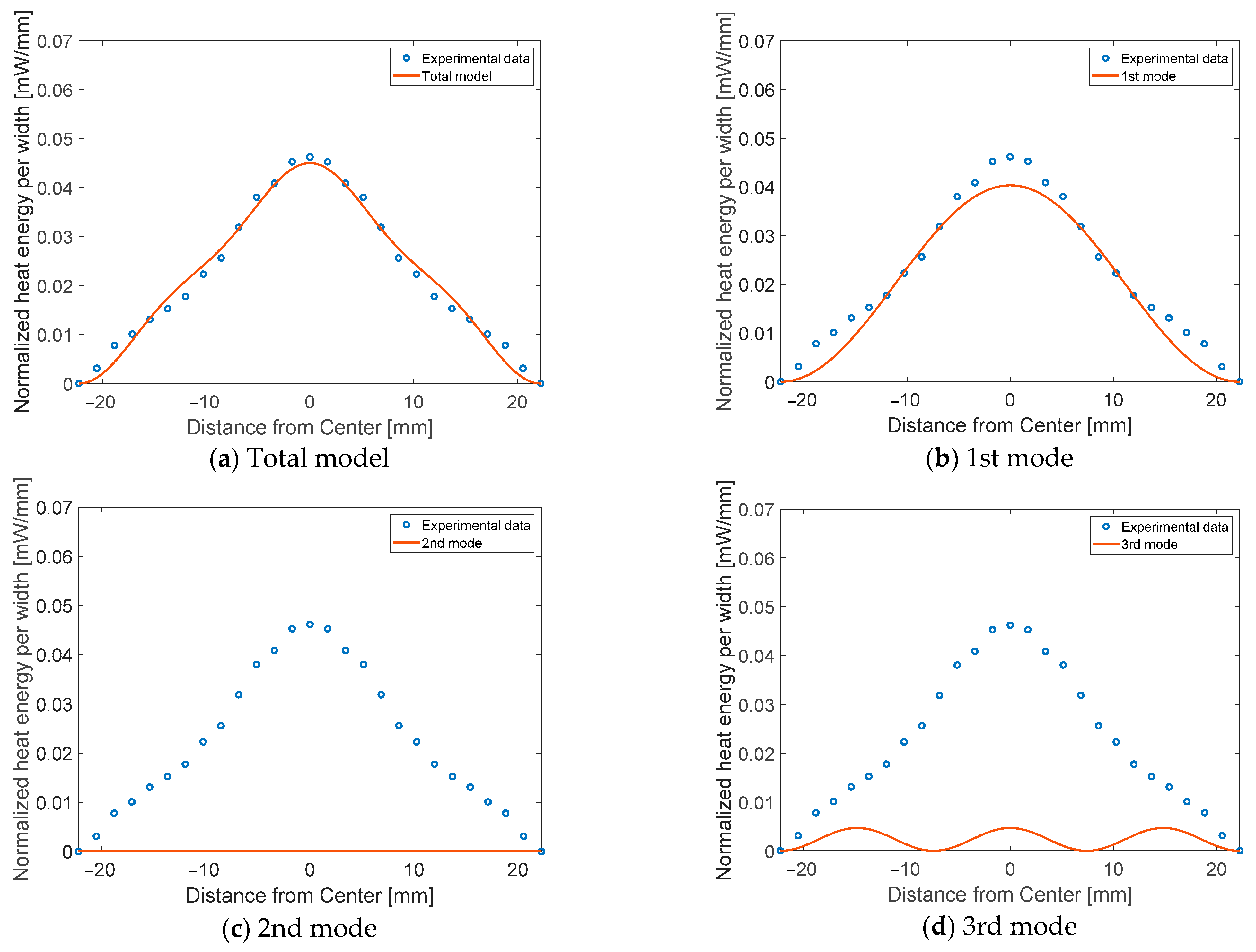
- In the proposed model, the 1st eigenmode was dominant, consistent with the design purpose of the reflector to focus maximum energy in a narrow area. The other modes are responsible for a certain amount of IR energy distributed by the imperfections of engineered conditions.
- The model was implemented into a FEM code to consider an electrical–thermal analysis of IR heating for a metal sheet. The FEM with the proposed model can accurately predict the experimental results of the focused IR heating.
- The results of this study show that the proposed approach can provide accurate and simpler modeling.
Author Contributions
Conceptualization, E.-H.L.; methodology, E.-H.L. and S.-H.O.; performing experiments, E.-H.L. and S.-H.O.; FEM analysis and data analysis, S.-H.O.; validation, E.-H.L. and S.-H.O.; writing—original draft preparation, S.-H.O.; writing—review and editing, E.-H.L. and S.-H.O.; supervision, E.-H.L. All authors have read and agreed to the published version of the manuscript.
Funding
This work was partially supported by the National Research Foundation of Korea (NRF) grant (No. 2021R1C1C1007946) funded by the Korea government and Test & System Package (TSP) Division at Samsung Electronics Co., Ltd.
Institutional Review Board Statement
Not applicable.
Informed Consent Statement
Not applicable.
Data Availability Statement
Data sharing not applicable.
Conflicts of Interest
The authors declare no conflict of interest.
Appendix A
This section presents the IR power meter used and details of the heat flux measurement process in the calibration of the model. Figure A1a,b shows the IR heater with the 40 mm focal length and the IR power meter used in the measurements, respectively. Figure A2 presents a schematic drawing of the heat flux measurement. After drilling a hole in a metal sheet, the IR intensity was measured at different positions through the drilled hole from the center to the end. The calibration results are explained in Section 2.3.
Figure A1.
Measurement devices: (a) IR lamp; (b) IR power meter.
Figure A2.
Measurement process of IR intensity.
References
- Krishnamurthy, K.; Khurana, H.K.; Soojin, J.; Irudayaraj, J.; Demirci, A. Infrared heating in food processing: An overview. Compr. Rev. Food Sci. Food Saf. 2008, 7, 2–13. [Google Scholar] [CrossRef]
- Sandu, C. Infrared radiative drying in food engineering: A process analysis. Biotechnol. Prog. 1986, 2, 109–119. [Google Scholar] [CrossRef] [PubMed]
- Aboud, S.A.; Altemimi, A.B.; RS Al-HiIphy, A.; Yi-Chen, L.; Cacciola, F. A comprehensive review on infrared heating applications in food processing. Molecules 2019, 24, 4125. [Google Scholar] [CrossRef] [PubMed] [Green Version]
- Rastogi, N.K. Recent trends and developments in infrared heating in food processing. Crit. Rev. Food Sci. Nutr. 2012, 52, 737–760. [Google Scholar] [CrossRef]
- Tsai, S.R.; Hamblin, M.R. Biological effects and medical applications of infrared radiation. J. Photochem. Photobiol. B Biol. 2017, 170, 197–207. [Google Scholar] [CrossRef] [Green Version]
- Rushwin, S.T. Infrared drying of paint. Cent. Mater. Fabr. 1989, 3, P0108. [Google Scholar]
- Riadh, M.H.; Ahmad, S.A.B.; Marhaban, M.H.; Soh, A.C. Infrared heating in food drying: An overview. Dry. Technol. 2015, 33, 322–335. [Google Scholar] [CrossRef]
- Lee, E.H.; Yang, D.Y.; Yoon, J.W.; Yang, W.H. A manufacturing process using the infrared ray local heating method for seat cross members. Int. J. Adv. Manuf. Technol. 2017, 89, 3299–3305. [Google Scholar] [CrossRef]
- Lee, E.H.; Yoon, J.W.; Yang, D.Y. Study on springback from thermal-mechanical boundary condition imposed to V-bending and L-bending processes coupled with infrared rays local heating. Int. J. Mater. Form. 2018, 11, 417–433. [Google Scholar] [CrossRef]
- Lee, E.H. A review on applications of infrared heating for food processing in comparison to other industries. Innov. Food Processing Technol. A Compr. Rev. 2020, 431–455. [Google Scholar] [CrossRef]
- Lee, E.H.; Yang, D.Y. Design and analysis of infrared heating with overlapping heater array scheme for industrial application. Heat Transf. Eng. 2018, 39, 1344–1354. [Google Scholar] [CrossRef]
- Hou, Z.; Li, X.; Huang, Y.; Ho, S.T. Physics of elliptical reflectors at large reflection and divergence angles I: Their design for nano-photonic integrated circuits and application to low-loss low-crosstalk waveguide crossing. Opt. Commun. 2013, 287, 96–105. [Google Scholar] [CrossRef]
- Hou, Z.; Li, X.; Huang, Y.; Ho, S.T. Design of high efficiency elliptical reflector for strongly guiding waveguide. In Frontiers in Optics; FThC2; Optical Society of America: Washington, DC, USA, 2010. [Google Scholar]
- Sharma, G.P.; Verma, R.C.; Pathare, P. Mathematical modeling of infrared radiation thin layer drying of onion slices. J. Food Eng. 2005, 71, 282–286. [Google Scholar] [CrossRef]
- Purlis, E. Baking process design based on modelling and simulation: Towards optimization of bread baking. Food Control 2012, 27, 45–52. [Google Scholar] [CrossRef] [Green Version]
- Purlis, E. Optimal design of bread baking: Numerical investigation on combined convective and infrared heating. J. Food Eng. 2014, 137, 39–50. [Google Scholar] [CrossRef]
- Bagheri, H.; Kashaninejad, M. Kinetic modeling of mass transfer during roasting of soybeans using combined infrared-hot air heating. J. Food Biosci. Technol. 2018, 8, 1–12. [Google Scholar]
- Seyhun, N.A.D.İ.D.E.; Ramaswamy, H.; Sumnu, G.; Sahin, S.; Ahmed, J. Comparison and modeling of microwave tempering and infrared assisted microwave tempering of frozen potato puree. J. Food Eng. 2009, 92, 339–344. [Google Scholar] [CrossRef]
- Sun, X.; Zheng, Z.; Liu, X.; Gu, P. Etendue analysis and measurement of light source with elliptical reflector. Displays 2006, 27, 56–61. [Google Scholar] [CrossRef]
- Dong, X.; Ashman, P.J.; Nathan, G.J.; Sun, Z. Optical design of a high flux solar simulator configurable to achieve either a line or a point focus. In Proceedings of the Chemeca 2013: Challenging Tomorrow, Brisbane, QLD, Australia, 29 September–2 October 2013. [Google Scholar]
- Lee, E.H.; Yang, D.Y.; Yang, W.H. Numerical modeling and experimental validation of focused surface heating using near-infrared rays with an elliptical reflector. Int. J. Heat Mass Transf. 2014, 78, 240–250. [Google Scholar] [CrossRef]
- Lee, E.H.; Kim, W.S. Electrical–thermal–mechanical analysis of focused infrared heating Process. Int. J. Precis. Eng. Manuf. Green Technol. 2020, 7, 885–903. [Google Scholar] [CrossRef]
- Kim, T.H.; Park, S.H.; Lee, E.H.; Kang, Y.H.; Chung, J.S.; Ha, J. A New Mechanical Cold Trimming Process Assisted by Dashed Lined Infrared Heat Treatment of Martensitic Steel Considering Energy Efficiency. Int. J. Precis. Eng. Manuf. Green Technol. 2022, 1–22. [Google Scholar] [CrossRef]
- Takahashi, K.Y. Distribution functions in classical and quantum mechanics. Prog. Theor. Phys. Suppl. 1989, 98, 109–156. [Google Scholar] [CrossRef] [Green Version]
- Schrödinger, E. An undulatory theory of the mechanics of atoms and molecules. Phys. Rev. 1926, 28, 1049. [Google Scholar] [CrossRef]
- De Broglie, L. Waves and quanta. Nature 1923, 112, 540. [Google Scholar] [CrossRef]
- De Broglie, L. Recherches sur la Théorie des Quanta. Ph.D. Thesis, Migration-Université en Cours D’Affectation, Paris, France, 1924. [Google Scholar]
- Born, M. Statistical interpretation of quantum mechanics. Science 1955, 122, 675–679. [Google Scholar] [CrossRef] [Green Version]
- Han, J.; Zhang, L.; Weinan, E. Solving many-electron Schrödinger equation using deep neural networks. J. Comput. Phys. 2019, 399, 108929. [Google Scholar] [CrossRef] [Green Version]
- Hermann, J.; Schätzle, Z.; Noé, F. Deep-neural-network solution of the electronic Schrödinger equation. Nat. Chem. 2020, 12, 891–897. [Google Scholar] [CrossRef]
- Wismer, M.S.; Kruchinin, S.Y.; Ciappina, M.; Stockman, M.I.; Yakovlev, V.S. Strong-field resonant dynamics in semiconductors. Phys. Rev. Lett. 2016, 116, 197401. [Google Scholar] [CrossRef] [Green Version]
- Feit, M.D.; Fleck Jr, J.A. Solution of the Schrödinger equation by a spectral method II: Vibrational energy levels of triatomic molecules. J. Chem. Phys. 1983, 78, 301–308. [Google Scholar] [CrossRef]
- Griffiths, D.J.; Schroeter, D.F. Introduction to Quantum Mechanics, 3rd ed.; Cambridge University Press: Cambridge, UK, 2018; pp. 1–12. ISBN 978-1-107-18963-8. [Google Scholar]
- Zhang, P.; Zhang, S.; Liu, X.; Qiu, L.; Yi, G. A Least Squares Ensemble Model Based on Regularization and Augmentation Strategy. Appl. Sci. 2019, 9, 1845. [Google Scholar] [CrossRef] [Green Version]
- Griffiths, D.J. Introduction to Electrodynamics, 4th ed.; Cambridge University Press: Cambridge, UK, 2017; p. 222. ISBN 978-1-108-42041-9. [Google Scholar]
- Cortés, A.; Jiménez-Suárez, A.; Campo, M.; Ureña, A.; Prolongo, S.G. Assessment of Manufacturing Parameters for New 3D-Printed Heating Circuits Based on CNT-Doped Nanocomposites Processed by UV-Assisted Direct Write. Appl. Sci. 2021, 11, 7534. [Google Scholar] [CrossRef]
- Lipp, V.; Rethfeld, B.; Garcia, M.; Ivanov, D. Solving a system of differential equations containing a diffusion equation with nonlinear terms on the example of laser heating in silicon. Appl. Sci. 2020, 10, 1853. [Google Scholar] [CrossRef] [Green Version]
- Chiriac, G.; Lucache, D.D.; Nițucă, C.; Dragomir, A.; Ramakrishna, S. Electric Bus Indoor Heat Balance in Cold Weather. Appl. Sci. 2021, 11, 11761. [Google Scholar] [CrossRef]
- Lee, E.H.; Yang, D.Y.; Yoon, J.W.; Yang, W.H. Numerical modeling and analysis for forming process of dual-phase 980 steel exposed to infrared local heating. Int. J. Solids Struct. 2015, 75, 211–224. [Google Scholar] [CrossRef]
Publisher’s Note: MDPI stays neutral with regard to jurisdictional claims in published maps and institutional affiliations. |
© 2022 by the authors. Licensee MDPI, Basel, Switzerland. This article is an open access article distributed under the terms and conditions of the Creative Commons Attribution (CC BY) license (https://creativecommons.org/licenses/by/4.0/).