Abstract
Fault dislocation severely threatens the safety of a tunnel structure. Formerly, researchers mainly engaged in the mechanical response of mountain tunnels crossing the fault fracture zone. In contrast, few studies have focused on the structural stress characteristics and joint deformation of the cross-fault shield tunnels. There is an apparent difference between segmental tunnels and mountain tunnels with respect to mechanical properties. In the current study, a three-dimensional numerical model of cross-fault segmental tunnels is established based on the theory of concrete plastic damage constitutive relations using the finite element program ABAQUS. The numerical calculation results are compared with the model test results for validation. Subsequently, the relevant factors affecting the mechanical response of the shield tunnel crossing the active fault are analyzed. The results illustrate that when normal fault dislocation occurs, the shield tunnel structure is initially damaged appearing in the circumferential joints, which is prone to large tension deformation. Otherwise, when reverse faulting occurs by the same displacement, the shield tunnel structure is initially damaged at the arch haunch of the segments, and the deformation of the longitudinal joints is relatively slight. Under the same fault displacement, the bearing capacity of the segmental lining subjected to the reverse fault dislocation is more significant than that of the normal fault dislocation. Both the soil elastic modulus and the vertical distance between the top of the fault and the tunnel exert a considerable impact on the structural damage of the segmental tunnels, bolt stress, and joint deformation. The fault dip angle does not affect the mechanical characteristics of the shield tunnel structure when subjected to normal fault displacement. In reverse faulting cases, with the increase of the fault dip angle, the tunnel structural failure mode transforms from the transverse compression failure of the segments to the shear failure of the circumferential joints.
1. Introduction
The dislocation of active faults seriously threatens the safety of tunnel structures across faults. Fault dislocation is always accompanied by forced displacement, which causes structural cracks and large deformation on an existing tunnel, and even leads to the overall failure of the tunnel structure. Usually, the relevant design codes recommend that the proposed project should be far away from the area affected by the fault dislocation. However, it is difficult to accurately determine the position of the buried fault in the preliminary survey because the buried fault is usually overlaid with a certain thickness of the soil layer. Therefore, it is impracticable to completely keep the influence area of fault dislocation in the early stage of the tunnel construction. Due to the severe impact of fault dislocation on existing tunnels, it is crucial to research the mechanical response of tunnel structures across faults.
Currently, model tests [,,,] and numerical simulation [,,,] are mainly used to investigate the mechanical response of the cross-fault tunnels, and most of them take mountain tunnels crossing fault zones as the research object [,]. Gypsum is commonly used to simulate the tunnel structure and the failure characteristics of the tunnel structure in model tests. Centrifugal tests can simulate the soil−structure interaction more realistically and obtain deformation characteristics of the strata, and this method has achieved an excellent application performance in the cross-fault tunnel model test [,]. Seismic research of cross-fault tunnels is also a research hotspot. On the basis of the shaking table test, the dynamic mechanical properties of cross-fault tunnels are systematically studied [,,]. In comparison with the model test, the numerical simulation method has the advantages of a low research cost and high efficiency [,], and is an important means of scientific research in the field of underground engineering. The numerical simulation method has been proven to be a feasible method for studying the influence of fault dislocation on the tunnel []. Guo et al. (2021) [] used numerical simulation to study the crack propagation law of the tunnel structure subjected to the stick-slip dislocation of the reverse fault. Based on the concrete damage theory, Zhong et al. (2020) [] studied the damage evolution mechanism of strike-slip fault dislocation on water conveyance tunnel structures. The flexible design method of the structural segment can reduce the influence of fault dislocation on a tunnel structure to a certain extent. Some researchers have used numerical simulation to study the fault-resistant effect of segmented flexible joints [,,].
Compared with traditional mountain tunnels, segmental tunnels have numerous segmental joints and are primarily used in the soil strata, resulting in a distinct difference in the mechanical response of fault dislocation []. By carrying out a centrifugal test of cross-fault shield tunnel with a scaling ratio of 1:30, Kiani et al. (2016) [] studied the deformation characteristics of a shield tunnel structure and the joints subjected to fault dislocation, then obtained the failure mode of the tunnel structure. Hu et al. (2009; 2010) [,] conducted a 1:5 scale constant gravity model test, where the deformation and the failure mechanism of a shield tunnel structure under the condition of oblique crossing buried ground fissures at different angles were studied. Based on the longitudinal stiffness equivalent theory of a shield tunnel, Li et al. (2022) [] investigated the influence of hidden faults on the longitudinal force of existing shield tunnels using the indoor model test. Liang et al. (2020) [] modeled a shell-spring model for the segmental tunnel crossing active faults by ABAQUS, the effect of fault dislocation on the damage of the tunnel structures and joint deformation was studied, and corresponding seismic measures were proposed. Lunardi et al. (2017) [] developed a shield tunnel anti-seismic joint based on the Greek Thessaloniki subway crossing active fault project. The anti-seismic joint can largely accommodate the forced displacement caused by the fault dislocation on the tunnel structure, and thus reduce the impact simultaneously.
Formerly, most numerous studies have contributed to continuous mountain tunnels, and some researchers proposed setting up flexible joints to resist fault dislocation. Due to the apparent difference between segmental tunnels and continuous tunnels in structural form and structural failure characteristics, the above research results are difficult to be directly applied to segmental tunnels. Meanwhile, the stiffness and strength of the segmental joints are relatively weak, making it challenging to resist more considerable fault displacement. There are few studies focusing on the mechanical response of segmental tunnels across faults, and the mechanical properties of shield tunnels subjected to fault dislocation have not been entirely revealed. Therefore, it is of great practical significance to understand the mechanical response of shield tunnels under fault dislocation. In this paper, on the basis of the project of Jinan Rail Transit Line 4 shield tunnel crossing the Qianfoshan fault zone, a 3D numerical model of the cross-fault segmental tunnel is established using the finite element program ABAQUS, which has significant advantages in nonlinear analysis and is widely used in the civil engineering field []. The influence of fault dislocation on the existing shield tunnel is assessed, and the characteristics of structural stress and joint deformation are further analyzed.
2. Numerical Modeling
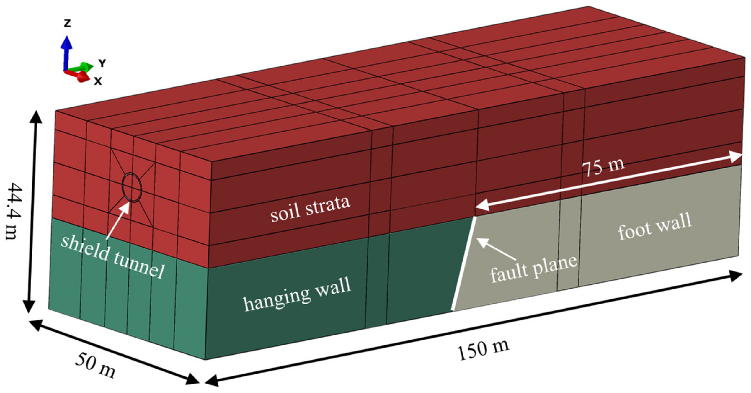
2.1. Engineering Background
The proposed shield tunnel of Jinan Rail Transit Line 4 passes through the Qianfoshan fault fracture zone. The fault movement is dominated by tensile normal faults; the dip angle of the fault plane ranges from 70° to 80°; and the overlying stratum is mainly plain fill, gravel, clay, and cemented gravel. The karst site around the proposed tunnel is strongly developed, and the fault fracture zone here has water conductivity. High-pressure karst water may conduct water through the fault, adversely affecting the tunnel construction.
The soil thickness above the segmental tunnel in this project is approximately 8 m, and the tunnel passes mainly through the cemented gravel and gravel layer. The engineering geologic profile is shown in Figure 1. In this project, the structural parameters of the segments and bolts are comprehensively determined based on the beam-spring calculation model, commonly adopted in China, and supplemented by the engineering analogy method. According to the tunnel design, the outer diameter of the segmental tunnel is 6.4 m; the inner diameter is 5.8 m; and the thickness and the width of the segmental ring are 0.3 m and 1.2 mm, respectively. The strength class of concrete for the precast segments is C50. Sixteen pieces of M27 bolts of 6.8 grade are placed between the circumferential joints, and two pieces of M27 bolts of 6.8 grade are placed between the longitudinal joints.
Figure 1.
Engineering geologic profile of the shield tunnel crossing the fault zone.
2.2. Overview of Numerical Models
A 3D numerical model of the shield tunnel across the fault was established by ABAQUS, as illustrated in Figure 2. Considering the boundary effects, the model size is L150 × W50 × H44.4 m. The size of the segments is based on the actual engineering value, the fault dip angle is assumed to be 75°, and the vertical distance between the top of the fault and the tunnel h is set to 10 m. For avoiding the interference of other factors in this study, only one fault was considered in the numerical modeling, and the ground layer above the fault was simplified as a single stratum. The physical and mechanical parameters of soil and bolts are illustrated in Table 1.
Figure 2.
3D numerical model of cross-fault segmental tunnel.
Table 1.
Physical and mechanical parameters.
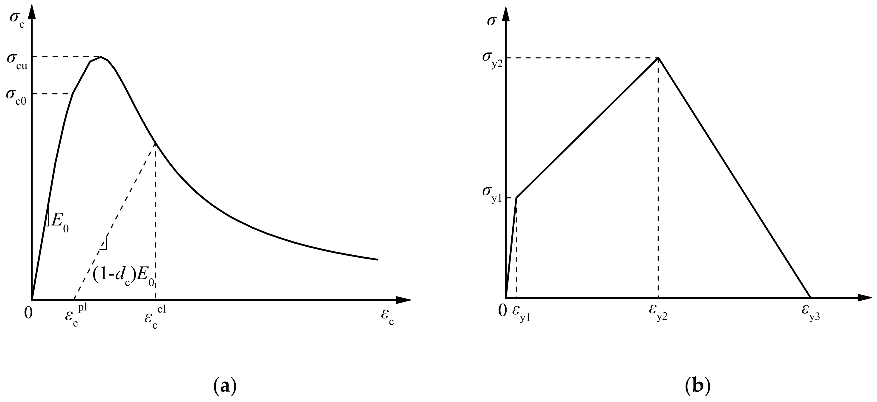
2.3. Constitutive Model and Contact Settings
We introduce the plastic damage constitutive of concrete to simulate the mechanical behavior of the tunnel segments. By introducing the uniaxial compressive damage factor dc and the uniaxial compressive damage factor dt (GB50010-2010, 2015) [], the plastic damage constitutive of concrete is applied to characterize the stiffness degradation characteristics of concrete structures caused by damage in the plastic stage. In ABAQUS, the concrete tensile and compressive damage factor Dk can be determined by the following formula:
where Dt and Dc are the tensile and compressive damage factors of concrete, respectively; fk,r is the representative value of the uniaxial tensile or compressive strength of concrete; εk,r is the representative value of the uniaxial tensile or compressive strength of the concrete corresponding to peak strain; Ec is the elastic modulus of concrete; and αt and αc are the values of the descending section of the uniaxial tensile stress–strain curve and the uniaxial compressive stress–strain curve, respectively.
Shen et al. (2007) [] proposed a damage-plastic constitutive model based on the equivalent material theory of reinforced concrete. In this constitutive model, the steel bars are replaced by an equivalent reinforced concrete model, and the strengthening characteristics are realized by defining the plastic stress–strain curve for tensile strengthening. The constitutive model can reasonably reflect the tensile failure characteristics of concrete. Figure 3 presents the equivalent plastic damage constitutive relation of concrete adopted in the study, in which the parameters of the tensile constitutive model of the equivalent materials can be determined by the following formula:
Figure 3.
Equivalent plastic damage constitutive relation of concrete. (a) Stress–strain curve of concrete under uniaxial compression, (b) stress–strain curve of equivalent material under uniaxial tensile.
In ABAQUS, the material parameters required for plastic damage constitutive of concrete include a dilation angle Ψ = 15°; flow potential offset κ = 0.1; biaxial and uniaxial ultimate compressive strength ratio σb0/σc0 = 1.16; invariant stress ratio Kc = 0.667; viscosity coefficient μ = 0.0005. The corresponding relation between tensile strain and damage value of concrete equivalent materials is illustrated in Table 2.
Table 2.
Relation between tensile strain and tensile damage factor.
In the numerical modeling, contact analysis is used to simulate the interaction behavior between segmental lining and between segments and soil, and all the contact properties are “hard contact”. “Hard contact” is also set on the fault plane, and fault plane separation is not permitted in the simulation []. Contact parameters for the numerical model are shown in Table 3.
Table 3.
Contact parameters in numerical model.
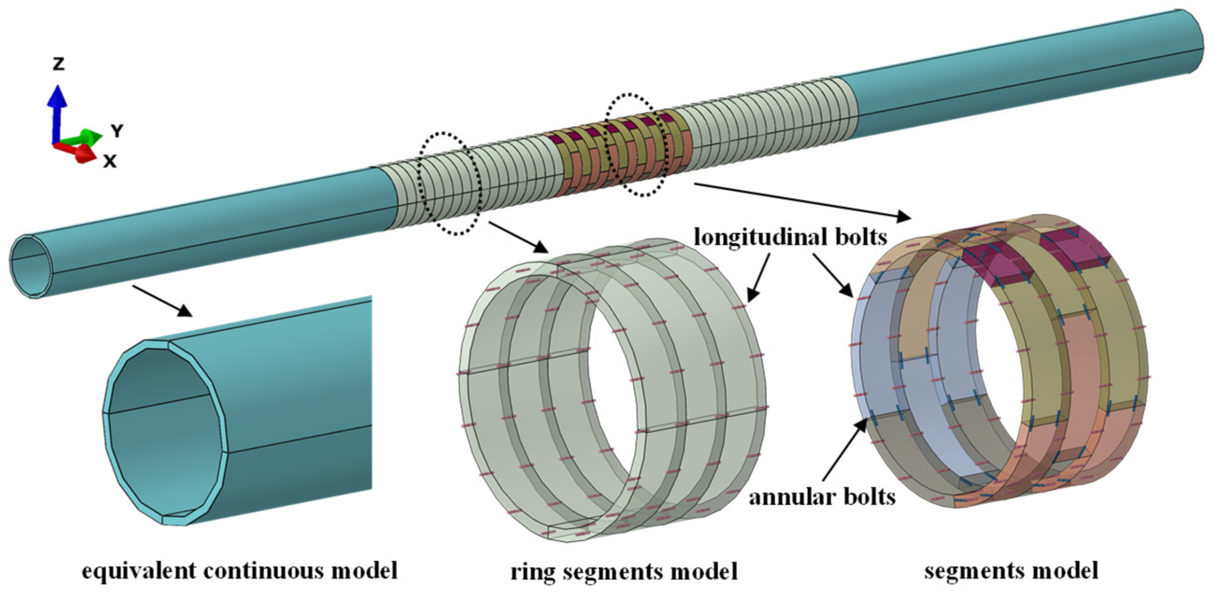
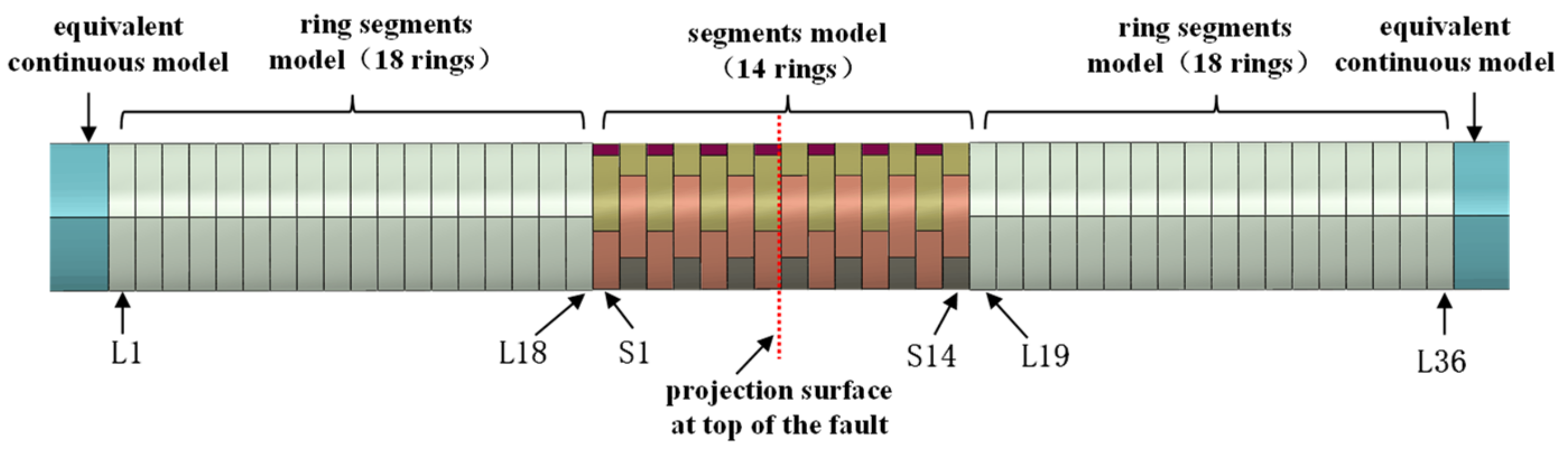
2.4. Segmental Tunnel Simulation
The segmental tunnel is simulated in three forms in view of the research priority and the computational costs. The segment structure is used near the fault dislocation surface, which can reflect the lateral force characteristics of the segmental tunnels more intuitively.
The segmental linings are simulated by annular segments close to the block segments. The remaining part of the tunnel structure is simulated by the longitudinal equivalent continuous model, and the longitudinal bending stiffness effective rate η can be determined in the work of Shiba et al. (1988) []. In this paper, η set to 0.0462. The bolts at the longitudinal and circumferential joints are embedded in the segment structure. The structural model of the shield tunnel structure is illustrated in Figure 4.

Figure 4.
Numerical model of the segmental tunnel.
2.5. Boundary Conditions and Simulation of Fault Movement
In the numerical modeling, the fault dislocation is simulated by the forced displacement method. For example, under normal fault dislocation, the boundary condition of the fault fixed plate is kept unchanged, and the surface displacement is applied on the bottom and the end face of the fault active plate. The direction of the surface displacement is parallel to the fault dislocation surface, and the fault displacement is loaded step by step.
Figure 5 shows the simulation method of the fault dislocation. In the numerical model, the mechanical response of the shield tunnel structure subjected to fault dislocation is realized in three steps. The first step is the initial stress balance. The second step is to perform one-time excavation and lining support of the shield tunnel by the stress release method. The third step is to apply fault dislocation step by step.
Figure 5.
Boundary conditions of the numerical model and the fault simulation method.
3. Analysis of Segmental Tunnel Influenced by Fault Movement
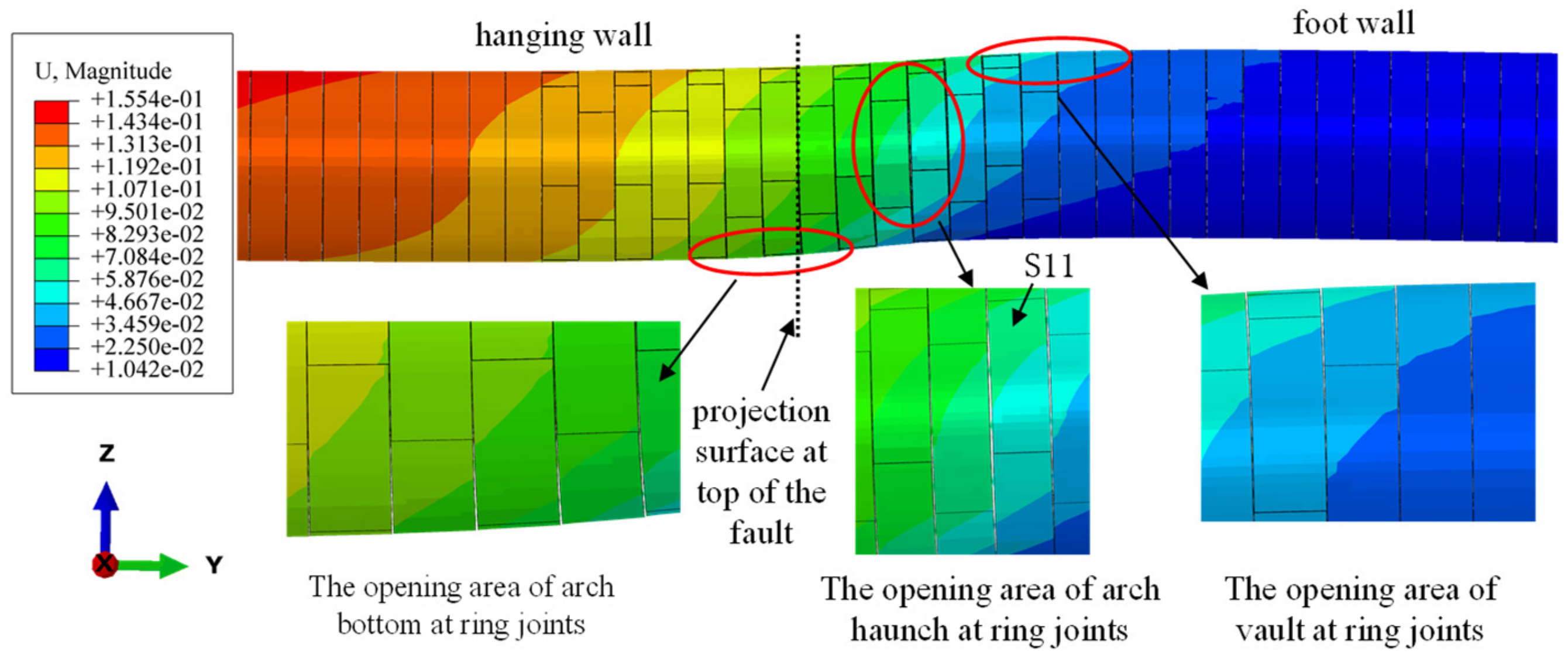
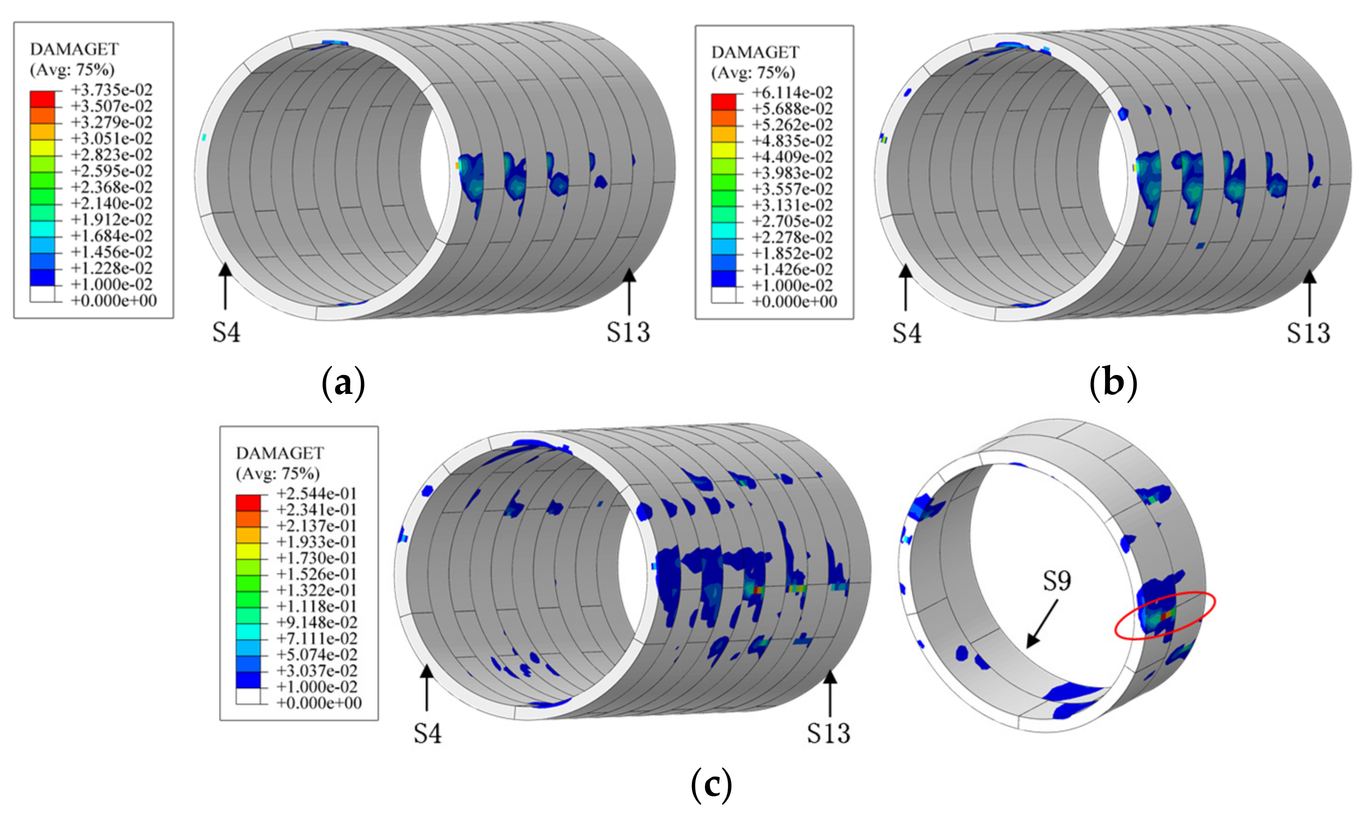
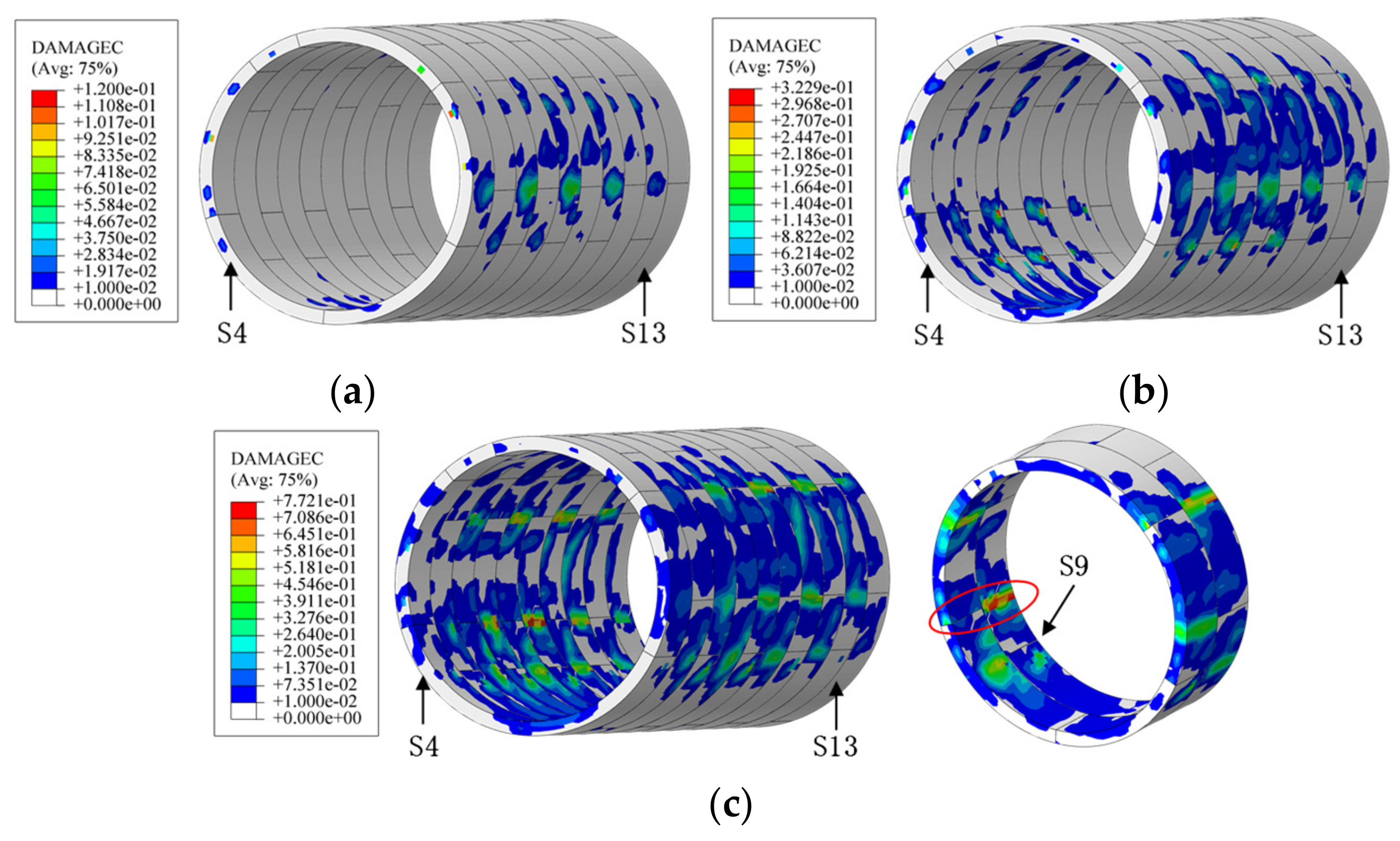
3.1. Mechanical Response of Segmental Tunnel
Figure 6 and Figure 7 illustrate the damage contours of the segmental tunnel subjected to normal faulting. When the normal fault dislocation of 5 cm is imposed, the tensile damage and compressive damage of the tunnel structure are slight, indicating that the structure is in a safe state. When the normal faulting of 10 cm is imposed, the tensile damage value is 0.298, and the compressive damage value is 0.417. In the moment, the fault dislocation caused non-negligible threats to the tunnel structure. When the fault displacement was 15 cm, the structural tensile and compressive damage exceeded 0.9, indicating that the tunnel structure was severely damaged.

Figure 6.
Tensile damage distribution of the segmental tunnel under normal fault dislocation: (a) under 5 cm fault displacement, (b) under 10 cm fault displacement, (c) under 15 cm fault displacement. Some like +3.484e-02 means 3.484 × 10⁻².
Figure 7.
Compressive damage distribution of segmental lining under normal faulting: (a) under 5 cm fault displacement, (b) under 10 cm fault displacement, and (c) under 15 cm fault displacement. Some like +9.770e-02 means 9.770 × 10⁻².
Meanwhile, it was found that when the 15 cm fault movement occurred, the structural damage of the segmental tunnel was mainly located at the circumferential joints, where the concrete is prone to apparent tensile and compressive damage. Therefore, it can be seen that the concrete at the circumferential joints is more likely to be damaged under normal faulting, and the most severely damaged area is located in the foot wall.
Kiani et al. (2016) [] conducted a centrifuge test for a cross-fault shield tunnel with a 1:50 similarity ratio, and then studied the effect of normal fault dislocation on the existing segmental tunnel. Figure 8 indicates the test results of the existing shield tunnel subjected to normal faulting. According to the model test results, the longitudinal bolts and the tunnel structure near the annular joints are damaged remarkably under the normal fault displacement.
Figure 8.
Model test results of the cross-fault segmental tunnel [].
Figure 9 shows the contour of the longitudinal deformation of the shield tunnel subjected to normal faulting. Under normal fault displacement, significant tension deformation occurs in the annular joints, and the tension deformation area includes the tunnel arch bottom of the hanging wall zone, the tunnel vault of the foot wall zone, and the tunnel arch haunch near the fault projection surface. On the basis of the characteristics mentioned above, the annular joint deformation of the segmental tunnel can be divided into three fields, namely the opening area of the arch bottom at the annular joints, the opening area of arch haunch at the annular joints, and the opening area of the vault at the annular joints.
Figure 9.
Shield tunnel deformation under normal fault dislocation. Some like +1.554e-01 means 1.554 × 10⁻¹.
The stress contours of the longitudinal and annular bolts subjected to normal fault movement are presented in Figure 10. When a fault movement of 15 cm was imposed, the maximum stress of the annular bolts was 394.7 MPa, which was less than the bolt yield stress of 480 MPa, and the maximum stress of the longitudinal bolts was 497.5 MPa, which means the bolt yielded at that moment. Therefore, under normal faulting, the annular joints of the segmental tunnel are more prone to cause large tensile deformation compared to longitudinal joints.
Figure 10.
Stress of the joint bolts subjected to normal fault dislocation: (a) stress of circumferential bolts and (b) stress of circumferential bolts. Some like +3.947e+08 means 3.947 × 10⁸.
Figure 11 and Figure 12 show the damage contours of the segmental tunnel subjected to reverse fault movement. When reverse faulting of 10 cm was imposed, the compressive damage of the tunnel structure was slight, and the structure was in a safe state. When reverse faulting of 15 cm was imposed, the maximum compressive damage value of the tunnel structure was 0.32, for which the compressive concrete was in the stage of stiffness degradation, corresponding to the damage value. When fault dislocation reached 20 cm, the compressive damage value was 0.77, indicating that the tunnel structure suffered severe compressive damage at this time. When fault dislocation of 15 cm was imposed, the maximum tensile damage of the structure was only 0.06. When the fault movement reached 20 cm, the tensile damage of the structure increased sharply, and the maximum tensile damage value was 0.254.
Figure 11.
Tensile damage distribution of the shield tunnel under reverse faulting: (a) under 10 cm fault displacement, (b) under 15 cm fault displacement, and (c) under 20 cm fault displacement. Some like +3.735e-02 means 3.735 × 10⁻².
Figure 12.
Compressive damage distribution of shield tunnel under reverse faulting: (a) under 10 cm fault displacement, (b) under 15 cm fault displacement, (c) under 20 cm fault displacement. Some like +1.200e-01 means 1.2 × 10⁻¹.
It can be observed that, under reverse faulting, the structural damage of the segmental tunnel was mainly located at the structural arch haunch, where the concrete is prone to suffer tensile and compressive damage, indicating that the tunnel structure at this time was mainly subjected to lateral force. Therefore, the tunnel segments are more likely to be collapsed under reverse fault displacement.
By comparing the structural damage of the segmental tunnel subjected to fault dislocation, it can be found that when the normal fault dislocation was 15 cm, the shield tunnel structure had significant local damage. However, when reverse fault dislocation of 15 cm was imposed, the shield tunnel structure still had a certain bearing capacity. The main reason can be explained as follows. Compared with the lateral bearing capacity of the segmental tunnel, the circumferential joints were the weak part of the shield tunnel. When the normal fault occurred, the shield tunnel was first damaged at the circumferential joints. When the reverse fault occurred, the shield tunnel was mainly subjected to lateral force, and the stress and deformation of the circumferential joints were relatively small. Therefore, under the same fault displacement, the effect of normal fault displacement on the segmental tunnel was more significant than that of reverse fault displacement.
The stress contours of the longitudinal and annular bolts subjected to the reverse fault dislocation are illustrated in Figure 13. When the fault dislocation reached 15 cm, the maximum stress of the annular bolts was 444.7 MPa and the maximum stress of the longitudinal bolts was 430.2 MPa, both of which were less than the bolt yield stress of 480 MPa. None of the bolts yielded at this time. Therefore, under reverse fault displacement, large tensile deformation of segmental joints rarely occurs.
Figure 13.
Stress of joint bolts subjected to reverse fault displacement. (a) Stress of circumferential bolts and (b) stress of circumferential bolts. Some like +4.447e+08 means 4.447 × 10⁸.
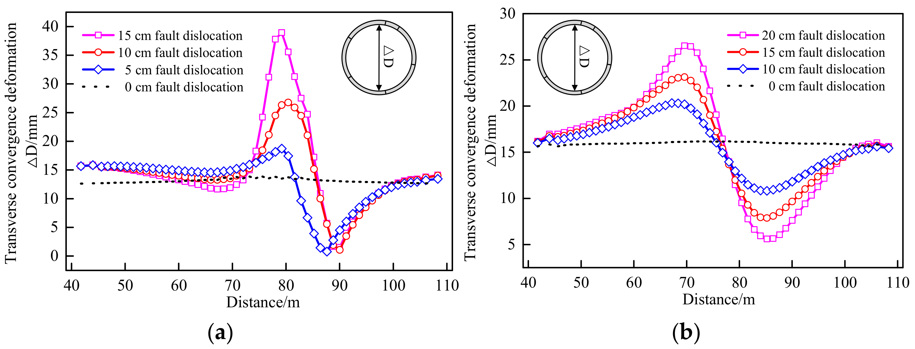
3.2. Deformation of Segmental Lining and Joints
Figure 14 illustrates the longitudinal and circumferential joint deformation of the segmental tunnel subjected to normal faulting. As can be seen, under normal fault displacement, the maximum deformation of longitudinal joints was located at the tunnel vault. When fault dislocation of 15 cm was imposed, the maximum opening of the longitudinal joints was 2.01 mm. The maximum deformation of the circumferential joints was located at the arch haunch, and when the fault dislocation reached 15 cm, the maximum opening of the circumferential joints was 6.82 mm. Because the deformation of the longitudinal joints was much smaller than that of the circumferential joints, it can be considered that, in the normal faulting cases, circumferential joint deformation is dominant in segmental joint deformation.
Figure 14.
Deformation of segment joints under normal fault dislocation. (a) Deformation of longitudinal joints and (b) deformation of circumferential joints.
The deformation of the segmental joints under reverse faulting is presented in Figure 15. It can be observed that, under the reverse fault dislocation, the maximum deformation of the longitudinal joints was at the arch haunch. When the fault displacement reached 20 cm, the maximum opening of the longitudinal joints was 1.1 m. When the fault displacement was 20 cm, the maximum opening of the circumferential joints was 0.84 mm, and the maximum deformation of the circumferential joints was located at the tunnel vault. Although the deformation of the longitudinal joints was slightly smaller than that of the circumferential joints, the deformation of both was small. It can be considered that the circumferential and longitudinal joints are not prone to large deformation under the reverse fault displacement condition.
Figure 15.
Deformation of segment joints subjected to reverse faulting. (a) Deformation of longitudinal joints and (b) deformation of -circumferential joints.
The lateral convergence deformation of the segmental lining subjected to fault dislocation is illustrated in Figure 16. The lateral convergence deformation of the segmental lining was significantly affected by the fault dislocation, and the maximum lateral convergence deformation of the tunnel segment was located near the projection surface of the top of the fault. When normal faulting of 15 cm was imposed, the maximum lateral convergence deformation of the segmental lining was 38.9 mm. However, when the reverse fault displacement of 20 cm was imposed, the maximum lateral convergence deformation of the tunnel segments was merely 26.5 mm, which implies that the maximum lateral convergence of the tunnel segments subjected to the normal fault dislocation is much larger than that under the reverse fault dislocation condition.
Figure 16.
Transverse convergence deformation of a shield tunnel under faulting: (a) normal faulting condition and (b) reverse faulting condition.
Although the segmental tunnel was mainly subjected to lateral force under reverse fault movement, the overall longitudinal compression state of the tunnel increased the capability of the tunnel structure to resist lateral deformation. Although the lateral convergence deformation of the segmental lining was relatively smaller than that of the normal fault dislocation, the concrete structure caused lateral crushing failure when the reverse fault displacement reached 20 cm.
4. Parametric Study and -Discussions
To study the main factors affecting the mechanical response of the shield tunnel structure across the fault, three variables, namely the elastic modulus of the stratum, the vertical distance h between the top surface of the fault and the tunnel, and the fault dip angle, were selected to analyze the influence of parameters. Among them, the elastic modulus of the stratum ranged from 20 to 90 MPa, the vertical distance h ranged from 5 to 20 m, and the fault dip angle ranged from 55° to 85°.
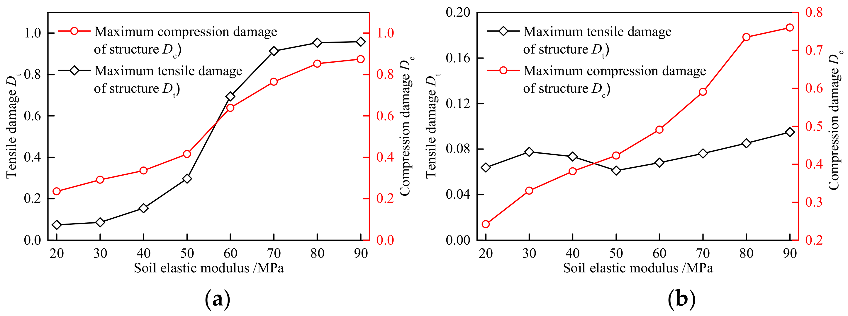
4.1. Elastic Modulus of Stratum Influence on Tunnel Behavior
Figure 17 shows the relation between the maximum damage value of the tunnel segments and the elastic modulus of soil subjected to 10 cm normal fault dislocation and 15 cm reverse fault dislocation. In the normal faulting cases, the tensile and compressive damage values of the segmental tunnel increased significantly with the increase of the elastic modulus of the stratum. In other words, under the same fault displacement distance, the larger the elastic modulus of the soil, the more severe the damage to the segmental linings.
Figure 17.
Effect of the elastic modulus of stratum on the structural damage of the segments: (a) normal faulting condition and (b) reverse faulting condition.
When the elastic modulus of soil was 20 MPa, the tensile damage value of the segments was 0.074, for which the tensile damage value of the segments was slight. When the elastic modulus of the stratum was 50 MPa, the tensile damage of the segments was 0.298, and the tensile damage value of the segmental lining increased sharply, which seriously threatened the safety of the tunnel structure. When the elastic modulus of the stratum was 70 MPa, the tensile damage value already exceeded 0.913, indicating that the concrete at the circumferential joints was damaged locally.
It can be seen from Figure 17b that under the reverse fault displacement condition, the compressive damage value of the shield tunnel was raised significantly with the increase of the elastic modulus of the soil, demonstrating that the compressive damage of the segments was significantly affected by the soil elastic modulus. The elastic modulus of the soil slightly affected the tensile damage value, and the tensile damage value of the segments remained in a small range.
Subjected to 10 cm normal fault displacement and 15 cm reverse fault displacement, the relation between the maximum stress of the longitudinal bolts and the elastic modulus of the stratum is illustrated in Figure 18. Under fault displacement conditions, the maximum stress of longitudinal bolts increased with the increase in the elastic modulus of soil, and the maximum stress of the annular bolts decreased with the increase of the elastic modulus of the stratum.
Figure 18.
Effect of the elastic modulus of stratum on the maximum stress of joint bolts: (a) normal faulting condition and (b) reverse faulting condition.
The maximum stress of the annular bolts was more significantly affected by the elastic modulus of the stratum. For example, under 15 cm reverse fault dislocation, when the soil elastic modulus increased from 20 MPa to 90 MPa, the maximum stress of the annular bolts decreased from 390.6 MPa to 230 MPa—the reduction accounted for 41%. By contrast, the maximum stress of longitudinal bolts increases from 361.6 MPa to 418.3 MPa, and the stress increase purely accounted for 15.7%.
The relation between the maximum deformation of segmental joints and the elastic modulus of soil is shown in Figure 19. In the normal faulting cases, the maximum opening of the annular joints increased nonlinearly with the increase of the elastic modulus of the stratum. Under the reverse fault displacement condition, the maximum opening of the longitudinal joint showed a nonlinear decrease with the increase of the elastic modulus of soil. In other words, under the same fault displacement, the larger the elastic modulus of soil, the smaller the opening of the longitudinal joints.
Figure 19.
Effect of the elastic modulus of stratum on the segmental joint deformation: (a) normal faulting condition and (b) reverse faulting condition.
The above research findings can be explained as follows. With the large elastic modulus of the stratum around the tunnel, due to the strong restraint ability of the stratum on the shield tunnel, the segmental tunnel was subjected to a large forced displacement and consequently caused severe structural damage and large joint deformation of the shield tunnel. On the contrary, with the small elastic modulus of the stratum around the tunnel, the soil around the shield tunnel would be compressed to a certain extent under fault dislocation, thereby reducing the forced displacement of the segmental tunnel to some degree.
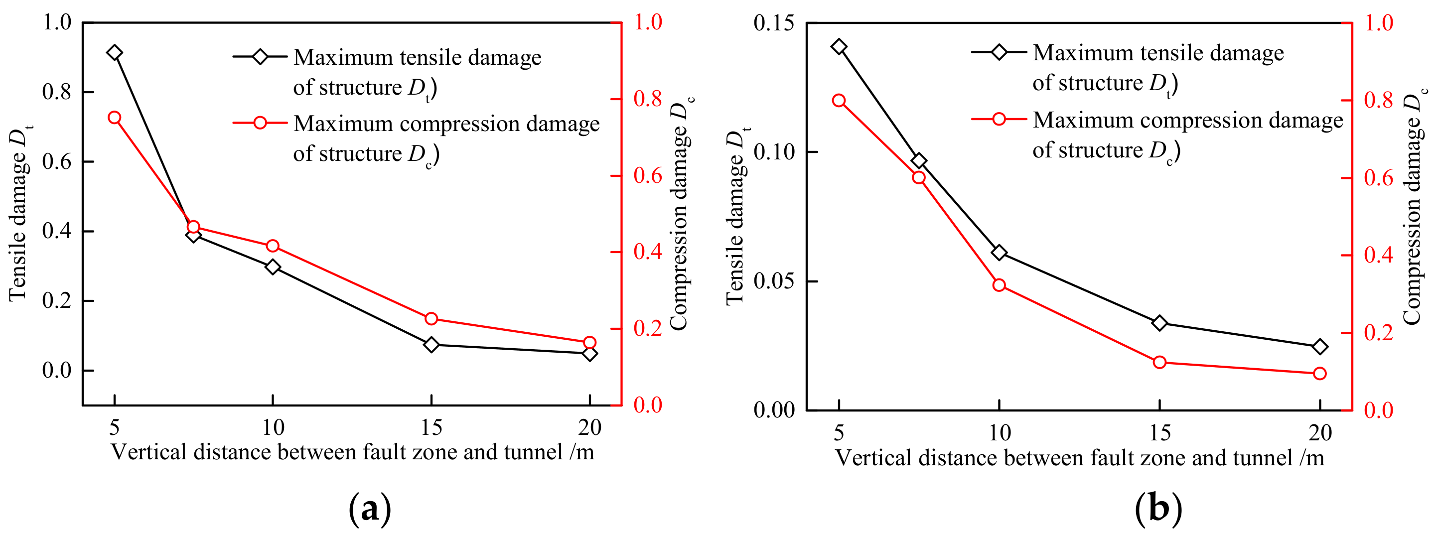
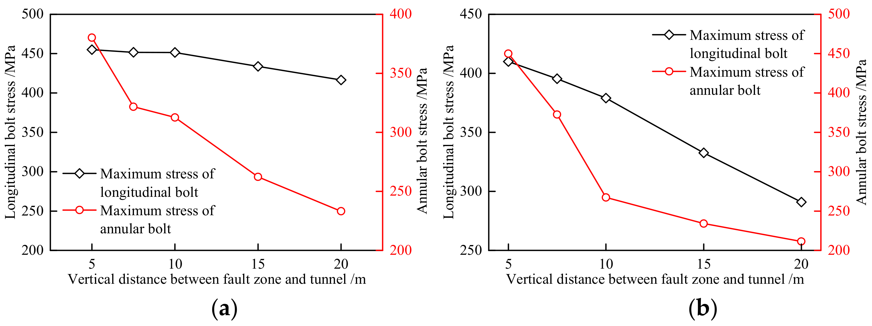
4.2. Vertical Distance between Fault Zone and Tunnel
Figure 20 shows the relation between the maximum damage value of thesegments and the distance h subjected to the normal faulting of 10 cm and the reverse faulting of 15 cm. The tensile and compressive damage values of the segmental lining decreased significantly with the increase of the distance h. With the increase of the distance h, the decreasing trend of the segmental lining damage was gradually weakened. When the distance was selected as h = 5 m, the tensile damage value of the structure was 0.9, and the concrete at the circumferential joints was partially damaged. When the distance h reached 7.5 m, the maximum tensile damage value was 0.41, for which the maximum tensile damage value of segments was significantly reduced. When the distance h reached 20 m, the tensile damage value of segments was 0.1, and the concrete at the annular joints was in a safe state.
Figure 20.
Effect of the vertical distance h on the structural damage of segmental lining: (a) normal faulting condition and (b) reverse faulting condition.
Under 10 cm normal fault displacement and 15 cm reverse fault displacement, the relation between the maximum stress of the longitudinal bolts and the distance is illustrated in Figure 21. The maximum stress of the ring and longitudinal bolts decreased with the increase of distance h. The vertical distance h increased from 5 m to 20 m, the maximum stress of the annular bolts reduced from 410 MPa to 260 MPa, and the stress reduction rate of the annular bolts was 15.7%.
Figure 21.
Effect of the vertical distance h on the maximum stress of joint bolts: (a) normal faulting condition and (b) reverse faulting condition.
Figure 22 illustrates the relationship between the maximum deformation of the segmental joints and the distance h. Under the fault movement, the maximum opening of the annular and longitudinal joints decreased with the increase of the vertical distance. In other words, under the same fault displacement, the smaller the distance, the larger the deformation of the segmental joints and the weaker waterproof performance of the segmental tunnel.
Figure 22.
Effect of the vertical distance h on the segmental joints deformation: (a) normal faulting condition and (b) reverse faulting condition.
The above research findings can be explained as follows. In the buried faulting cases, the soil between the shield tunnel and the top of the fault plane weakened the forced displacement caused by fault displacement, which had a certain protective effect on the existing tunnel. Therefore, it can be preliminarily concluded that the vertical distance h between the top of the fault plane and the existing tunnel is a key factor in evaluating tunnel safety.
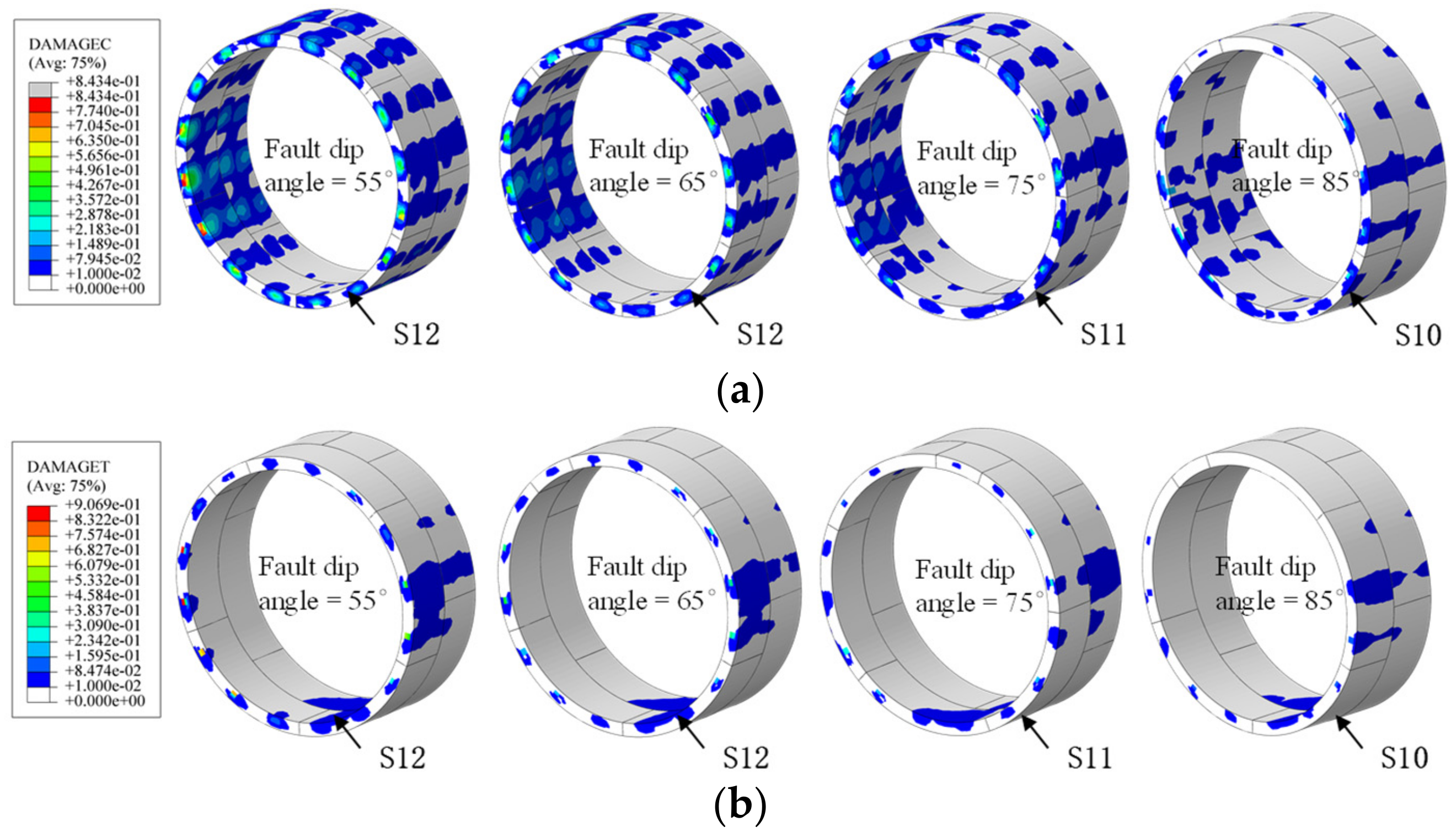
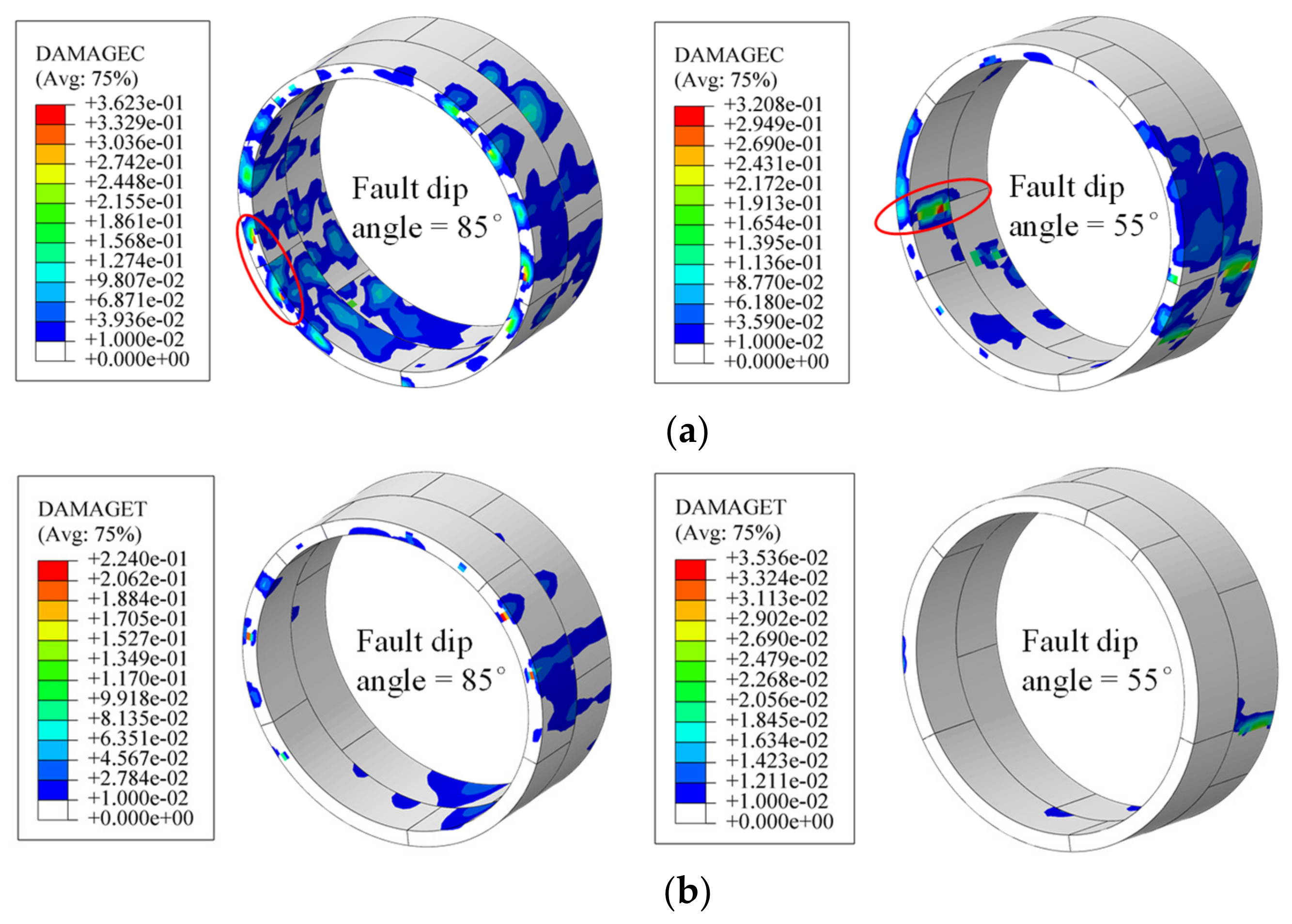
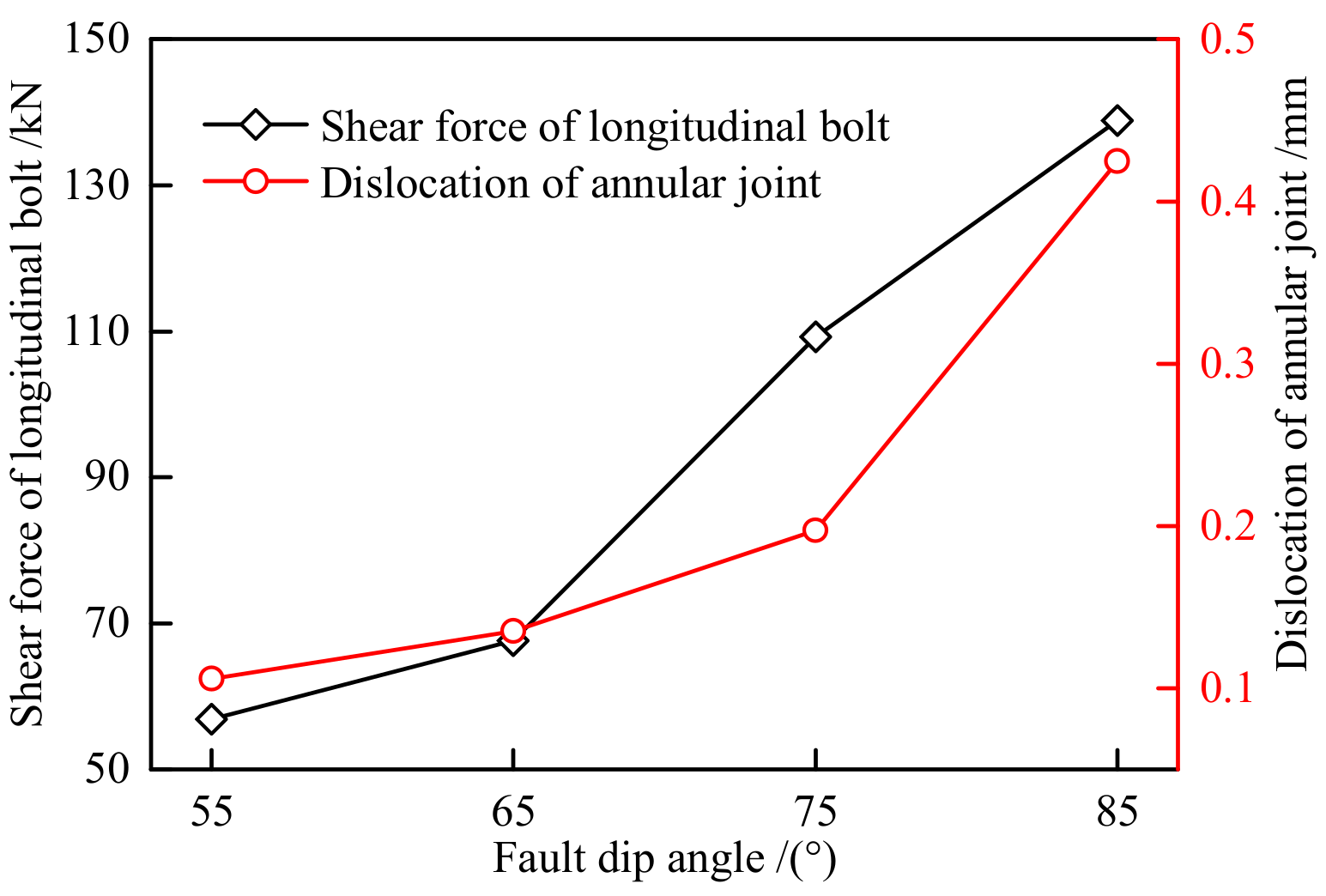
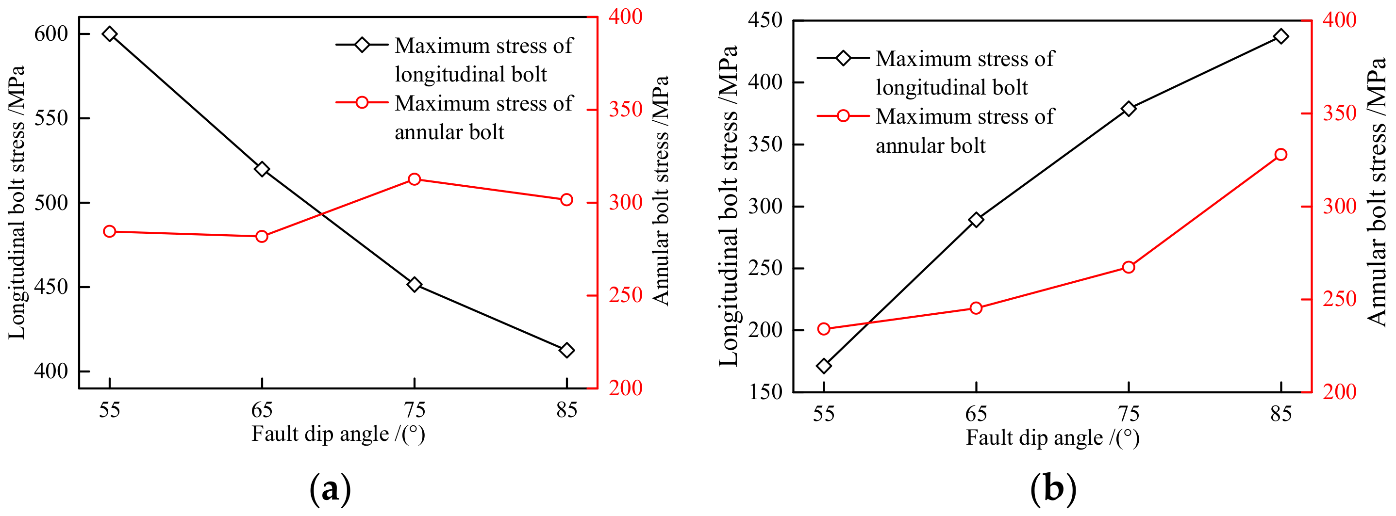
4.3. Fault Dip Influence on Tunnel Behavior
Figure 23 indicates the relationship between the tunnel structural damage and fault dip angles subjected to 10 cm normal faulting. The structural damage of the segmental tunnel decreased with the increase of the fault dip angle. When the fault dip angle increased from 55° to 85°, the maximum tensile damage value of the segmental lining decreased from 0.907 to 0.114. Moreover, the tensile and compressive damage of the segments were located at the circumferential joints. The result indicates that changing the fault dip angle does not significantly affect the structural stress state of the segmental tunnel under the normal fault dislocation condition.
Figure 23.
Development of structural damage changing with fault dip angle under normal faulting: (a) compression damage of segments and (b) tensile damage of segments. Some like +8.434e-01 means 8.434 × 10⁻¹.
The relation between the tunnel structural damage and fault dip angles subjected to 15 cm reverse fault displacement is presented in Figure 24. When the fault dip angle was 55°, the tensile and compressive damages of the segmental lining were located at the arch haunch, and the segments were mainly subjected to lateral force. When the fault dip angle was 85°, the tensile and compressive damages of the segmental lining were located at the circumferential joints, and the segments were mainly subjected to longitudinal stress. The main reason was that when the fault dip angle was larger, the longitudinal shear effect of the tunnel structure increased, and the annular joints could withstand much more shearing force. Therefore, concrete located at the circumferential joints is more likely to produce tensile and compressive damage. Therefore, under reverse fault displacement, the structural stress state of the segmental tunnel near the projection of the fault is significantly affected by the fault dip angle.
Figure 24.
Development of structural damage changing with fault dip angle under reverse faulting: (a) compression damage of segments and (b) tensile damage of segments. Some like +3.623e-01 means 3.623 × 10⁻¹.
Figure 25 illustrates the relationship between the maximum shear force of the longitudinal bolts, the displacement of circumferential joints, and the dip angle of the fault under different fault dip angles when reverse faulting of 15 cm was imposed. It can be observed from the figure that with the increase of the fault dip angle, the maximum shear force of the longitudinal bolts and the displacement of the circumferential joints increased significantly, for which it is extremely easy to produce shear failure.
Figure 25.
Effect of the fault dip angle on the shear force of longitudinal bolts and annular joints dislocation.
Figure 26 shows the relation between the maximum stress of the longitudinal bolts and the fault dip angle. Under 10cm normal fault displacement, the maximum stress of the longitudinal bolts decreased with the increase of the fault dip angle, and the annular bolts were less affected by the fault dip angle. Under 15 cm reverse faulting, the maximum stress of the annular bolts and longitudinal bolts increased with the increase of the fault dip angle. Since the longitudinal bolts were significantly affected by the fault dip angle subjected to normal and reverse fault displacement, reasonable longitudinal bolts should be selected in practical projects.
Figure 26.
Effect of the fault dip angle on the maximum stress of joint bolts: (a) normal faulting condition and (b) reverse faulting condition.
5. Conclusions
Considering the nonlinear characteristics of the segment joints and the plastic damage theory of concrete, a three-dimensional numerical model of the cross-fault segmental tunnel was established by ABAQUS. The mechanical response characteristics of the existing shield tunnel subjected to fault dislocation were investigated, and the relevant factors affecting the mechanical properties of cross-fault segmental tunnels were analyzed. The following main conclusions can be drawn from this study.
(1) When normal fault dislocation occurs, the shield tunnel structure is mainly subjected to longitudinal force, and the tunnel structure close to the annular joint is primarily damaged. Under reverse faulting, the shield tunnel structure is mainly subjected to lateral force, and the tunnel structure located at the arch haunch of the segments is initially damaged. The bearing capacity of the shield tunnel structure is more significant than that of the normal fault displacement.
(2) When normal fault dislocation of 15 cm is imposed, both the deformation of the circumferential joints and the longitudinal joints are large, and the tensile deformation of the circumferential joints is much larger than that of the circumferential joints. When the reverse faulting occurs by the same displacement, the deformation of the circumferential and longitudinal joints is relatively slight.
(3) Subjected to fault displacement, the larger the elastic modulus of the soil around the tunnel, the greater the forced displacement of the tunnel structure, and consequently, more severe structural damage and larger joint deformation of the segmental tunnel.
(4) In the buried faulting cases, the soil layer between the shield tunnel and the top of the fault plane weakens the forced displacement caused by fault displacement to some degree. As the vertical distance h between the top of the fault and the tunnel increases, the structural damage of the segmental tunnel, the stress of the longitudinal bolts, and the deformation of the longitudinal joints decrease significantly.
(5) In normal faulting cases, the stress characteristics of the segments are not significantly affected by the fault dip angle. Under the same fault displacement, the smaller the fault dip angle, the easier the tunnel linings suffer a tensile failure. When reverse fault displacement occurs, the fault dip angle significantly affects the stress characteristics of the segments near the projection of the fault. According to the results in the current study, when reverse faulting of 15 cm is imposed, the tunnel structure subjected to an 85° dip angle causes obvious shear deformation in the longitudinal direction. In contrast, the tunnel segments under a 55° dip angle are still mainly subjected to lateral force, and their longitudinal shear deformation is not obvious.
Author Contributions
H.L. and X.L.: conceptualization, methodology, project administration, and writing the original draft; Y.Y., Y.L. and M.M.: validation, plotting curves and analysis, and review. All authors have read and agreed to the published version of the manuscript.
Funding
This article was supported financially from the National Basic Research Development Program of China (No. 2015CB057800).
Institutional Review Board Statement
Not applicable.
Informed Consent Statement
Not applicable.
Data Availability Statement
Data are contained within this article.
Conflicts of Interest
The authors declare no conflict of interest.
References
- Cai, Q.P.; Peng, J.M.; Ng, C.W.; Shi, J.W.; Chen, X.X. Centrifuge and numerical modeling of tunnel intersected by normal fault rupture in sand. Comput. Geotech. 2019, 106, 108–116. [Google Scholar] [CrossRef]
- Wang, H.R.; Zhong, Z.L.; Zhao, M.; Wang, Z.; Zhao, X.; Du, X. Model experimental study of the influence of strike-slip fault dislocation on tunnel. J. Beijing Univ. Technol. 2021, 47, 691–701. [Google Scholar] [CrossRef]
- Wang, D.Y.; Cui, G.Y.; Yuan, J.X. Model tests on effect of dislocation reducing measures of stick-slip fault of tunnels. Chin. J. Geotech. Eng. 2018, 40, 1515–1521. [Google Scholar] [CrossRef]
- Wang, T.Q.; Cui, Z.; Sheng, Q.; Ning, B.K.; Ma, Y.L.N.; Zhou, G.X. Model experimental test and numerical analysis of the influence of a strike-slip fault on a tunnel project. IOP Conf. Ser. Earth Environ. Sci. 2020, 570, 032019. [Google Scholar] [CrossRef]
- Shahidi, A.R.; Vafaeian, M. Analysis of longitudinal profile of the tunnels in the active faulted zone and designing the flexible lining (for Koohrang-III tunnel). Tunn. Undergr. Space Technol. 2005, 20, 213–221. [Google Scholar] [CrossRef]
- Han, X.; Li, W. Numerical Analysis on the Structure Type and Mechanical Response of Tunnel Crossing Active Reverse Fault. Geofluids 2021, 2021, 5513042. [Google Scholar] [CrossRef]
- An, S.; Tao, L.J.; Bian, J.; Han, X.; Wu, X. Damage Analysis on Subway Tunnel Structure under Effect of Reverse Fault Dis-location. J. Hunan Univ. (Nat. Sci.) 2020, 47, 147–156. [Google Scholar] [CrossRef]
- Ranjbarnia, M.; Zaheri, M.; Dias, D. Three-dimensional finite difference analysis of shallow sprayed concrete tunnels crossing a reverse fault or a normal fault: A parametric study. Front. Struct. Civ. Eng. 2020, 14, 998–1011. [Google Scholar] [CrossRef]
- Liu, X.Z.; Li, X.F.; Sang, Y.L.; Lin, L. Experimental study on normal fault rupture propagation in loose strata and its impact on mountain tunnels. Tunn. Undergr. Space Technol. 2015, 49, 417–425. [Google Scholar] [CrossRef]
- Sun, F.; Zhang, Z.Q.; Yi, Z.W. Model experimental study of the influence of normal fault with stick-slip dislocation on subway tunnel structure. Rock Soil Mech. 2019, 47, 3037–3044, 3053. [Google Scholar] [CrossRef]
- Sabagh, M.; Ghalandarzadeh, A. Centrifugal modeling of continuous shallow tunnels at active normal faults intersection. Transp. Geotech. 2020, 22, 100325. [Google Scholar] [CrossRef]
- Yao, C.; He, C.; Takemura, J.; Feng, K.; Guo, D.; Huang, X. Active length of a continuous pipe or tunnel subjected to reverse faulting. Soil Dyn. Earthq. Eng. 2021, 148, 106825. [Google Scholar] [CrossRef]
- Yan, G.; Shen, Y.; Gao, B.; Zheng, Q.; Fan, K.; Huang, H. Experimental study of stick-slip fault crossing segmental tunnels with joints. Rock Soil Mech. 2019, 40, 4450–4458. [Google Scholar] [CrossRef]
- Cui, G.Y.; Wang, X.L. Model Test Study on the Antibreaking Technology of Reducing Dislocation Layer for Subway Interval Tunnel of the Stick-Slip Fracture. Adv. Civ. Eng. 2019, 2019, 1–9. [Google Scholar] [CrossRef]
- Shen, Y.S.; Wang, Z.Z.; Yu, J.; Zhang, X.; Gao, B. Shaking table test on flexible joints of mountain tunnels passing through normal fault. Tunn. Undergr. Space Technol. 2020, 98, 103299. [Google Scholar] [CrossRef]
- Kanik, M. Evaluation of the limitations of RMR89 system for preliminary support selection in weak rock class. Comput. Geotech. 2019, 115, 103159. [Google Scholar] [CrossRef]
- Alnmr, A. Material Models to Study the Effect of Fines in Sandy Soils Based on Experimental and Numerical Results. Acta Tech. Jaurinensis 2021, 14, 651–680. [Google Scholar] [CrossRef]
- Sabagh, M.; Ghalandarzadeh, A. Numerical modelings of continuous shallow tunnels subject to reverse faulting and its verification through a centrifuge. Comput. Geotech. 2020, 128, 103813. [Google Scholar] [CrossRef]
- Guo, X.Y.; Geng, P.; Ding, T.; Wang, Q.; Yang, Q.; He, Y. Mechanical behavior of tunnel under stick-slip action of reverse fault. J. Vib. Shock. 2021, 40, 249–258. [Google Scholar] [CrossRef]
- Zhong, Z.; Wang, Z.; Zhao, M.; Du, X. Structural damage assessment of mountain tunnels in fault fracture zone subjected to multiple strike-slip fault movement. Tunn. Undergr. Space Technol. 2020, 104, 103527. [Google Scholar] [CrossRef]
- She, F.T.; Li, Y.P.; Li, T.; Wang, S. Mechanical properties of split-tunnel-linning structure caused by buried ground fissuse propagation. China Earthq. Eng. J. 2020, 40, 684–691. [Google Scholar] [CrossRef]
- An, S.; Tao, L.J.; Han, X.C.; Zhang, Y. Application of two-level design method on subway tunnel crossing active fault: A case study on Urumqi subway tunnel intersected by reverse fault dislocation. Bull. Eng. Geol. Environ. 2021, 80, 3871–3884. [Google Scholar] [CrossRef]
- Zhao, K.; Chen, W.; Yang, D.; Zhao, W.; Wang, S.; Song, W. Mechanical tests and engineering applicability of fibre plastic concrete used in tunnel design in active fault zones. Tunn. Undergr. Space Technol. 2019, 88, 200–208. [Google Scholar] [CrossRef]
- Zaheri, M.; Ranjbarnia, M.; Dias, D.; Oreste, P. Performance of segmental and shotcrete linings in shallow tunnels crossing a transverse strike-slip faulting. Transp. Geotech. 2020, 23, 100333. [Google Scholar] [CrossRef]
- Kiani, M.; Akhlaghi, T.; Ghalandarzadeh, A. Experimental modeling of segmental shallow tunnels in alluvial affected by normal faults. Tunn. Undergr. Space Technol. 2016, 51, 108–119. [Google Scholar] [CrossRef]
- Hu, Z.P.; Peng, J.B.; Wang, Q.Y.; Zhu, Q.D.; Zhao, Z.R. Modeling test research on failure mechanism of shieldtunnel crossing ground fissure with 60°. Chin. J. Rock Mech. Eng. 2010, 29, 176–183. Available online: https://kns.cnki.net/kcms/detail/detail.aspx?FileName=YSLX201001022&DbName=CJFQ2010 (accessed on 22 February 2022).
- Hu, Z.P.; Peng, J.B.; Huang, Q.B.; Wang, Q.Y. Physical modeling test on shield tunnel crossing ground fissure with 30°. J. Chang. Univ. (Nat. Sci. Ed.) 2009, 29, 63–68. [Google Scholar] [CrossRef]
- Li, H.Y.; Li, X.G.; Ma, M.Z.; Liu, H.; Yang, Y. Model experimental study on influence of buried fault dislocation on shield tunnel. J. Zhejiang Univ. (Eng. Sci.) 2022, 56, 1–9. Available online: https://kns.cnki.net/kcms/detail/33.1245.T.20220105.1431.011.html (accessed on 22 February 2022).
- Liang, J.W.; Wu, Z.Q.; Xin, Y.; Ba, Z. Seismic counter- measures of shield tunnel under fault movement. Earthq. Eng. Eng. Vib. 2020, 40, 1–11. [Google Scholar] [CrossRef]
- Lunardi, P.; Cassani, G.; Canzoneri, A.; Carriero, F.; Bomben, G. Passage of a precast segmental lining tunnel through an active fault-Special segments and details-Thessaloniki metro. In Proceedings of the World Tunnel Congress 2017–Surface Challenges–Underground Solutions; JSCE: Bergen, Norway, 1966; pp. 37–44. Available online: https://www.rocksoil.com/pdf/269.pdf (accessed on 22 February 2022).
- Keskin, İ.; Ahmed, M.Y.; Taher, N.R.; Gör, M.; Abdulsamad, B.Z. An evaluation on effects of surface explosion on underground tunnel; availability of ABAQUS Finite element method. Tunn. Undergr. Space Technol. 2022, 120, 104306. [Google Scholar] [CrossRef]
- Liu, X.Z.; Cai, G.Y.; Yang, F.; Sang, Y.L.; Wu, J.X. Structural Bearing Behavior and Deformation Controlling Indicators for Staggered Jointed Shield Tunnel Lining in Fractured Surrounding Rock. China J. Highw. Transp. 2017, 30, 57–65. [Google Scholar] [CrossRef]
- GB 50010-2010 Code for Design of Concrete Structures; China Architecture & Building Press: Beijing, China, 2015. (In Chinese)
- Shen, X.P.; Wang, C.Y.; Zhou, L. A Damage Plastic Constitutive Model for Reinforced Concrete and Its Engi-neering Application. Eng. Mech. 2007, 24, 122–128. [Google Scholar] [CrossRef]
- Sun, F.; Zhang, Z.Q.; Qing, C. Research on Influence upon Tunnel Structure of Metro Line 1 in Urumqi Forced by Normal Fault Dislocation. China Railw. Sci. 2019, 40, 54–63. [Google Scholar] [CrossRef]
- Shiba, Y.; Kawashima, K.; Obinata, N.; Kano, T. An evaluation method of longitudinal stiffness of shield tunnel linings for application to seismic response analyses. Doboku Gakkai Ronbunshu 1988, 398, 319–327. [Google Scholar] [CrossRef]
Publisher’s Note: MDPI stays neutral with regard to jurisdictional claims in published maps and institutional affiliations. |
© 2022 by the authors. Licensee MDPI, Basel, Switzerland. This article is an open access article distributed under the terms and conditions of the Creative Commons Attribution (CC BY) license (https://creativecommons.org/licenses/by/4.0/).