1. Introduction
The current industry is characterized by increasing products complexity and personalization [
1,
2]. Products evolve by integrating advanced capabilities of sensing, communicating and by reacting to changing situations with increasing levels of reasonings. Smart manufacturing, usually gathered under the Industry 4.0 umbrella, supports such a scenario providing a means to answer to always different product specifications maintaining a high process efficiency and economic competitiveness [
3,
4,
5]. Manufacturing systems became more intelligent and autonomous due to the implementation of emerging communication, information and control technologies. Modern assets comprise advanced sensory apparatus, service-oriented computing platforms and modular controllers, integrating cyber–physical systems with high-fidelity simulation predictive models [
6]. In particular, the ongoing factory digitalization has inevitably changed not only the manufacturing but also the way that products are designed and consumed [
7].
Since modern markets continually demand flexible and customized products, development and commissioning processes are often very compressed [
8]. Simulation and virtual prototyping technologies are consolidating their role in transferring testing and optimization activities in virtual environments, pursuing realism, easiness of use and reliability [
9,
10,
11,
12]. Their application extends to the whole product life cycle [
7,
13] as well as the related production systems.
Nowadays, manufacturing plants require a higher adaptability, which is reached due to reconfigurable automation systems governed by advanced controllers, able to interpret operating scenarios and calculate and perform the optimal sequence of operations to achieve the best productivity and manufacturing quality in any condition. Thus, the control logics must embed the manufacturing knowledge and intelligence needed to interpret the surrounding environment and generate the optimal robust strategies. The programming of such intelligent robotic manufacturing has become increasingly complex and challenging, requiring a long time for verification and validation. Furthermore, it must be noted that modern robotic cells are governed by multiple controllers, namely at least a programmable logic controller (PLC) and a robot controller, whose control logics must be coordinated [
14].
Therefore, from the initial design stages, the cells’ offline development and debugging is usually performed via the use of virtual prototyping software (i.e., general-purpose computer-aided engineering or specific computer-aided robotics packages—see [
15,
16])—where the layout of the cell, along with its behavior, can be modeled and simulated [
17]. In these tools, the cell geometry, kinematic of robots and other devices, and the governing logic can be represented, including exchanged signals and sequences of commands to be executed. To obtain high-fidelity models, it is beneficial to include real hardware and/or software elements (e.g., commercial control units) in the virtual environment, which will be then become part of the implemented solution. These approaches, known as hardware-in-the-loop and software-in-the-loop [
16,
18], respectively, are the bases for an effective virtual commissioning (VC) strategy for concurrent engineering problems [
19]. They provide the capability of developing and testing complex plants before their implementation.
In a mechatronic system, due to the large variety of involved devices, an efficient VC must connect different hardware and software elements, allowing for the use of the same interface and interaction modality for both the real and virtual counterparts. Current virtual prototyping solutions often suffer from limited interaction capabilities with other software/hardware devices available on the market [
20]. Therefore, the need of interfacing tools enabling the communication between different components (following standards and architectures of industrial communication protocols) becomes crucial.
In this context, the present work proposes a method, and its implementation into an integrated tool, for the complete VC of robotic cells. The reported tool enables the concurrent simulation of PLC and robot programs within a realistic virtual model of the robotic system [
21], significantly reducing the plant development time and providing a means for generating, representing and validating information before its installation. In this way, the sequence of operations of each device can be effectively verified and optimized on a standard PC, without any required use of the physical assets. In fact, the multiple controllers’ contributions to the final robotic manufacturing performance are tested with a CAD-based digital prototype performing the activities (debugging, performance optimization, safety and fault-tolerant verification and validation) that are traditionally addressed during the physical commissioning of the cell. The considered software are RobotStudio (RS) and TwinCAT (TC), namely the robot simulation and the IEC-61131 PC-based automation packages provided by ABB and Beckhoff, respectively. Although these commercial platforms have been frequently employed for the design of robotic cells, each environment has been separately researched and implemented. Therefore, the main contribution of this research is to provide an improved VC approach, which integrates the simulation capabilities of RS and TC and allows users to analyze and optimize cell behavior in an accurate and efficient manner. This same approach can be extended to other commercial platforms.
The remainder of the paper discusses the integration between RS and TC and reports a demonstrative case study. It is organized as follows:
Section 2 briefly recalls the previous work inherent to VC.
Section 3 describes the proposed VC tool, involving aspects about the communication and the features employed in the definition of the application;
Section 4 presents the case study used to test the application;
Section 5 reports obtainable results from the application of the proposed system; and finally,
Section 6 reports conclusions and considerations regarding the future directions.
2. Related Work
Since traditional commissioning is proven to be time- and cost-consuming, many authors have thoroughly investigated VC technology during the last few years. The VC is a technique that aims to validate the control software of a manufacturing system with a simulation model, in a virtual environment and in an early stage of its commissioning process [
22,
23]. A great advantage apported by the VC is that many design activities can be parallelized. This makes it possible for different engineers to work together simultaneously, reducing the designing time [
24]. Additionally, it allows for possible errors to be detected and corrected, improving the performance of the entire robotic cell prior to its installation [
25,
26,
27].
A determining factor for an efficient VC is its capability to combine technologies from different engineering fields so as to create a holistic environment where all the aspects of the manufacturing systems are considered at the same time [
28,
29]. Despite some recent advances, a severe absence of integrated simulation-based platforms can be noted in the standard industrial practice [
24]. Digital plant models still divide the geometry and physics of the system from the PLC control program and signals, which are tested within the control software development tool (i.e., without a direct vision of the process behavior). Alternatively, by exploiting the open platform communications (OPC) protocol, the real PLC system can be connected with a 3D virtual model of the cell, defined in DELMIA or Dymola environments, as in [
30,
31]. An example of OPC coupling, realized through the WINMOD and SIMIT packages, can be seen in [
18,
32], but it is limited to the Siemens platform, while open IEC-61131 PLC programs should also be emulated.
Some software producers are heading towards the development of a single application that includes both devices’ kinematic and PLC program simulations. In [
33], a manufacturing cell was simulated using Process Simulate, namely a specialized software that is part of Siemens Tecnomatix suite and offers a 3D modeling environment where the user can test the connection between mechatronic devices and a PLC. Similarly, Simumatik3D was employed in [
25] to model a didactic robotic cell for a pick and place purpose and to test the related PLC control program. A relevant improvement provided by this software (compared to Process Simulate) is that PLCs of any vendor can be simulated. A common disadvantage, instead, regards their relatively poor robot simulation capabilities. In fact, robot movements can only be approximated since there is no real virtual controller running on the application, only a generic emulator. From the literature review, it emerges that one of the main limitations of VC solutions for robotic cells is related to the scarce realism of the simulated automated plant. Therefore, the only viable strategy for achieving highly reliable models seems to be the integration of dedicated commercial platforms [
32,
34]. Multi-software frameworks have been widely investigated by academic researchers in recent years, and not only regarding VC. They have been employed, e.g., for the design of servo-actuated mechanisms [
12,
35,
36], the dynamic characterization of robotic systems [
37], and for the tuning of robot controllers [
38].
In this context, the main objective of this work is to develop and test a novel VC tool that leverages the integration between RS and TC. Since the software TC turns a PC into a real-time controller, the proposed approach can be utilized to either:
Test a real PLC system, i.e., realizing the so-called hybrid commissioning as a part of the hardware-in-the-loop approach;
Simulate its behavior on a standard PC, i.e., realizing a full VC with a software-in-the-loop approach.
The PLC programs are tested in RS, where exact copies of the ABB controller and settings are available, obtaining extremely accurate robot replicas. During the simulations, RS provides several performance indices, such as kineto-dynamic outputs (end-effector or joint position, velocity, acceleration, jerk, motor torque, etc.), as well as information regarding the current robots’ energy consumption, cycle time and tasks execution. Another clear advantage in employing RS is the possibility for the user to support the design of customized cell layouts. The behavior of robots and other devices can be faithfully modeled, and design changes can be applied with minimum effort.
In conclusion, compared to the referenced solutions, the proposed tool provides the following practical contributions:
The virtual application is easy and rapid to set up;
The RS environment is straightforward and has a short learning curve;
No third-party software are needed as connection means;
The PLC interacts with the virtual cell as it would with the real cell;
The PLC programming on the virtual environment is completely reusable in the final commissioned (i.e., physical) system.
3. Proposed Virtual Commissioning Approach
In this section, the proposed software architecture is described starting from a brief introduction of the two main software systems (RS and TC). Then, details about the novel software component and its logic, which were developed to enable the integration between RS and TC, are provided. A demonstrative video of the proposed VC tool can be viewed at
Supplementary.
3.1. Integrated Software Tools
RS was chosen as the software tool to represent the virtual cell since it offers functionalities to model the geometrical layout, kinematic of devices, physical behavior, and control logic. RS originates as an offline programming software for ABB robots. Due to its virtual controller technology, RS can carry out extremely realistic simulations of the movements of the ABB robots and execute complex RAPID robot programs. Indeed, the software running on the real robot controllers (RobotWare) is the same as that utilized by the virtual robot controllers. Additionally, provides gives the possibility to model or import 3D geometries of other devices as well as to implement smart components (SCs). These are reusable blocks, including geometry, kinematics and functioning logics that can be utilized to realize the desired abstraction of real devices. Some basic SCs are provided by default in RS and can be combined to build more complex ones.
In addition, ABB offers a developing tool to extend the basic functionalities of the software, namely the RS Software Development Kit (SDK). Due to the SDK, users can develop new applications by exploiting the Microsoft Visual Studio environment, such as add-ins or customized SCs, expanding software potentialities.
On the other hand, TC is the software used for configuring and programming Beckhoff devices, including servo drives and PLCs. A PLC program can be written using several languages, such as ladder diagram, instruction list, function block diagram, structured text and sequential function chart (SFC). Such programs control the task execution flow of the entire cell, exchanging signals with the controls of the robots, motors, linear axes and other devices. The PLC runs on a hardware system that is capable of real-time performance, essentially a dedicated PC that ensures the cycles are executed in a timely manner.
These two software have no native way of communicating with each other. However, in order to create a complete VC of a robotic cell, it is essential to emulate contributions of each controller (namely, PLC and robot controller) with specific simulation tools that must be coupled and synchronized. This is the reason for the implementation of a tool that allows data exchange between TC and RS.
3.2. Architecture of the Virtual Commissioning System
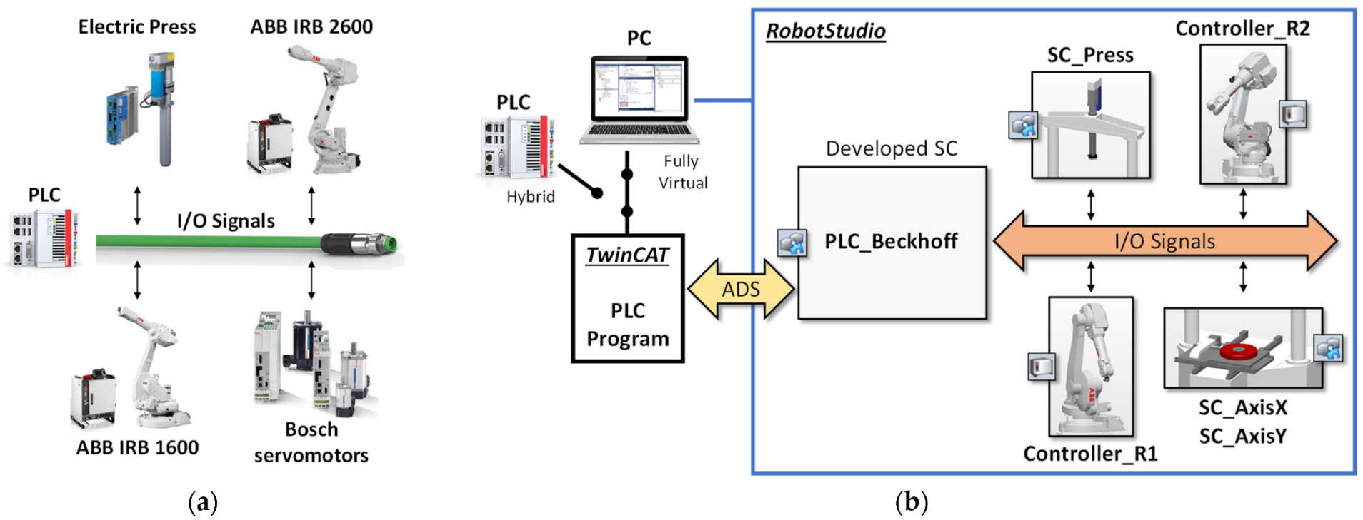
The main idea of the proposed approach is to replicate the physical automation solution architecture in a virtual environment (in the specific case RS) referring to a one-to-one mapping between real physical components and their digital representations. As shown in the left part of
Figure 1, in the industrial practice, a robotic cell is usually governed by one PLC, which exchanges signals with other automation modules, i.e., controllers of robots, motors, etc. The signal can represent any type of data, e.g., Booleans, integers and real data. The communication is conveyed referring to a field bus, which is physically implemented as a cable connecting the controllers and cell devices in series.
The right side of
Figure 1 depicts the proposed VC solution. The PLC system is maintained as a cell governing tool (hybrid solution) or optionally substituted by a PC running an emulated PLC for a fully virtual strategy. Each physical device is represented in the prototyping software platform as a virtual module, which is designed to have the same interface of the real counterpart, in terms of exchanged signals and expected behavior. Such virtual models are realized as SCs, leveraging the functionalities and abstraction capabilities of RS by providing to the user the possibility of defining reusable blocks, which encapsulate geometrical definitions, kinematics, sensors and control logics. The level of detail in the representation of the single device is a compromise between the necessary realism and the overall performance of the simulation environment. In particular, aspects that influence the performance of the PLC must be accurately modelled, such as dynamic or synchronized activities. Contrastingly, physically based computations that accurately represent systems performance may be demanding in terms of resources, so they must be limited to the parts where they provide the necessary realism and coherence with the represented behavior, as discussed in [
39].
Analogously, the flow of signals on the field bus is seamlessly linked to a flow of virtual signals in the virtual environment. The communication between the PLC and the virtual environment is obtained by a connection interface developed as a SC. This component, named PLC_Beckhoff, mimics the presence of the real PLC in RS. The connection to the real PLC is established through the automation device specification (ADS) protocol, which is provided by Beckhoff for linking the devices of a control chain. Since ADS Advanced Programming Interfaces (API) are available for MS NET Framework platform, the C# programming language was used to develop the PLC_Beckhoff SC to read and write the values of the variables defined in the TC PLC program.
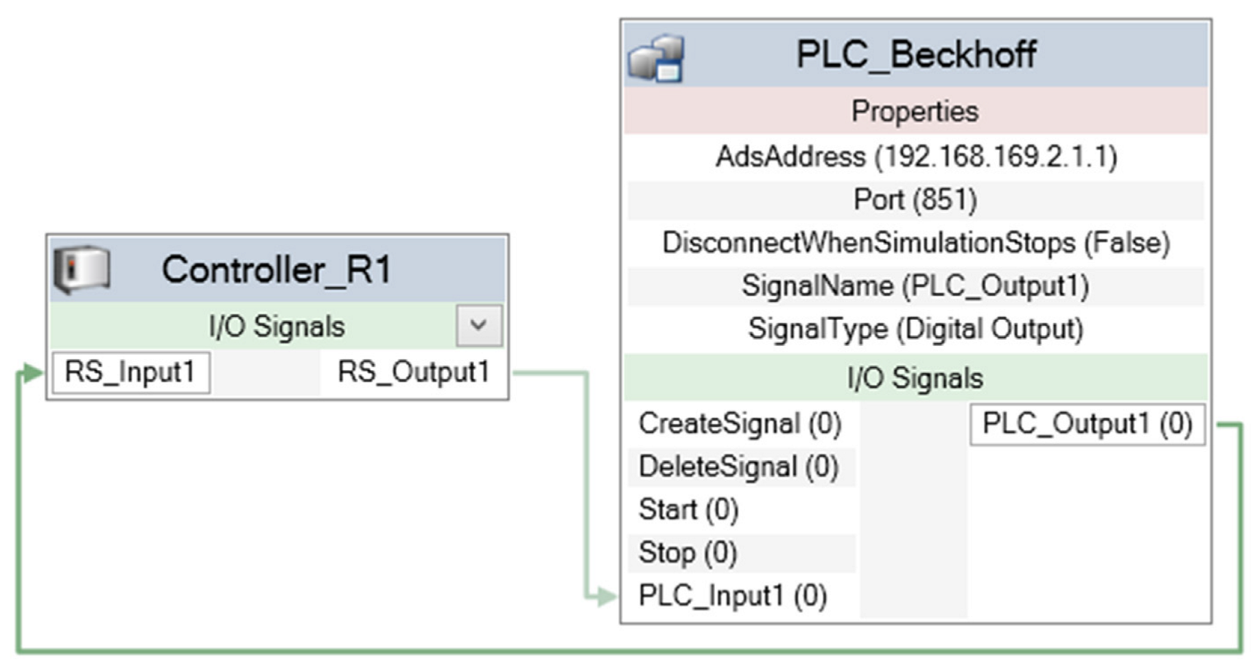
From the PLC point of view, the PLC_Beckhoff SC acts as a real element of the control chain and exchanges real signals on the field bus. Contrastingly, the component is integrated in the virtual environment of RS so that it can read and write the virtual signals used to control the synthetic environment. The usage of the SC in RS is quite straightforward since it provides the possibility to freely add signals that the user wants to exchange with the PLC simply by naming them as they appear in the PLC code. For instance,
Figure 2 shows how the two signals RS_Input1 and RS_Output1, defined in the robot controller Controller_R1, are linked to the PLC variables PLC_Output1 and PLC_Input1, respectively. The two latter variables are searched in the TC running code and the values are automatically synchronized by the SC.
3.3. Description of the PLC_Beckhoff Smart Component Interface
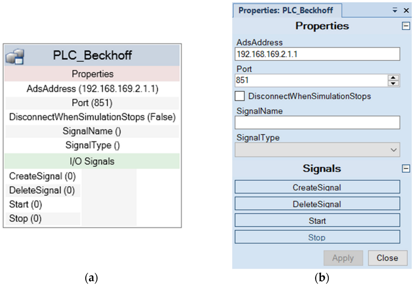
In this section, a description of the PLC_Beckhoff SC user interface is provided. In the RS environment, a SC interface is subdivided into Properties and I/O Signals, as shown in
Figure 3. Concerning the I/O section, four default signals were provided as pulsed type, in order to appear to the user as buttons to activate signal management functions, namely CreateSignal, DeleteSignal, Start and Stop. These signals’ names are reserved and therefore excluded from the exchange mechanism via ADS communication. They are used to operate and configure the SC to create a new signal with a given name, delete a signal, start an ADS connection, and stop the connection, respectively.
In the Properties section, AdsAddress and Port are the two fields required by the ADS protocol to reach the TC PLC and establish the communication. Once they are filled in, clicking on the button Start, a connection attempt will be made: if the connection fails, an error message will be displayed in the RS output messages window. The property DisconnectWhenSimulationStops is a Boolean value that determines if the ADS connection must be interrupted or not when the RS simulation is stopped.
The last two properties, SignalName and SignalType, are involved in the creation or deletion of a signal. Once the related fields are filled in, the button CreateSignal will instantiate a signal of the specified type, and it will be added to the SC custom signals list. Similarly, a signal can be removed from the mentioned list by writing its name in the SignalName property and then clicking on the DeleteSignal button. The setup phase ends ensuring that each TC variable that must be exchanged with RS is added to the SC.
3.4. Description of the Signal Exchange Mechanism
As mentioned before, according to the devices utilized in the cell and the required signals, the user adds the necessary I/O signals, providing a name which corresponds to the desired variable in TC to be connected. As an example, a variable could be named as “MAIN.Robot1.busy”. This means that, in the PLC code, a variable named “busy” is searched in the instance “Robot1” of a function block that likely includes the characteristics of a specific robot type; the instance “Robot1” has been declared in the program organization unit (POU) named “MAIN”. Essentially, such expedient represents a direct means to map RobotStudio signal names to TC variables.
In the following, pseudocode of the PLC_Beckhoff SC (Algorithm 1) outlines the initialization of the communication by mapping the RS signals to TC variables. IOS refers to the collection of signals managed from the PLC_Beckhoff SC, which is cycled to instantiate a SignalMapInfo object mi for each element to be mapped with the PLC. Such objects are then stored in two sets, named SI (i.e., input signals of the PLC_Beckhoff SC, going from RS to TC) and SO (i.e., output signals of the PLC_Beckhoff SC, going from TC to RS). To synchronize the value of an RS signal with TC and vice versa, the mapping data include:
A reference to the RS signal object;
A pointer to the handle properly created to reach the desired variable in TC from the user specified name;
The last exchanged value of the signal.
| Algorithm 1 Communication initialization |
InitializeCommunication()
in: TC client host name tcHostName,
TC client port name tcPortName,
set of IO Signals IOS from RS
out: TC connected client ads
set of input signals SI (from RS to TC)
set of output signals SO (from TC to RS)
local: current RS signal s being considered,
signal mapping info mi
1: ▷ Instantiation of the ADS connection
2: ads ← connect (tcHostName, tcPortName)
3: ▷ Instantiation of the signal maps
4: |MI| ← 0
5: |MO| ← 0
6: ▷ Instantiation of a signal info map mi to TC for each RS signal
7: for all s ∈ IOS do
8: case name(s) of
9: “Start”: ▷ Nothing to do
10: “Stop”: ▷ Nothing to do
11: “CreateSignal”: ▷ Nothing to do
12: “DeleteSignal”: ▷ Nothing to do
13: others:
14: ▷ Instantiate and populate mapping info mi
15: mi ← CreateMappingInfo(s)
16: rsSignal(mi) ← s
17: tcHandle(mi) ← CreateTCVariableHandle(ads, name(s))
18: lastValue(mi) ← value(s)
19: ▷Add mi to the proper set
20: if isInput(mi) then
21: AddElement(MI, mi)
22: else
23: AddElement(MO, mi)
24: end if
25: end case |
When the button Start is clicked, the ADS connection is established and the handle variables are automatically created due to the initialization procedure described above. After that, RS simulation can also be run. As long as the simulation is active, an event handler called OnSimulationStep is called for every RS elementary simulation step. The code executed at each step iteration includes two methods:
RobotStudioReadTwincatWrite, which updates the values of variables in TC from signal changes in RS;
TwincatReadRobotStudioWrite, which changes the status of signals in RS as a variable value is changed in TC.
The pseudocode of the first of the two functions is reported below (Algorithm 2). The other function has a specular structure. For each mapped signal, the value in RS is read and the corresponding variable in TC is updated. An optimization strategy is used to avoid useless operations. The last registered value is stored in the mapping info object, and it is compared with the new value in the next cycle in order to skip the writing operation if the value has not changed. This strategy allows the communication overhead to be reduced and makes the signals synchronization faster.
| Algorithm 2 Update variables in TC |
RobotStudioReadTwincatWrite(ads, MI)
in: client ads connected to TC,
set MI of the mapping infos of the input signals (from RS to TC)
local: current mapping info mi being considered,
current value cv of a signal
1: for all mi ∈ MI do
2: cv ← currentValue(mi)
3: if cv ≠ lastValue(mi) then
4: ▷ Write cv in TC variable using ads client
5: Write (ads, tcHandle(mi), cv)
6: lastValue(mi) ← cv
7: end if |
4. Case Study: Robotic Assembly Cell
The approach described in
Section 3 has been applied to a robotic assembly cell for gearboxes. The virtual model of the cell was realized in RS starting from a CAD representation of the real implemented prototype. The developed case allowed the VC capabilities of the proposed approach to be tested in a complex scenario made of two robots and various additional systems. In particular, the interaction mechanism between the PLC and the virtual representation of the cell devices is reported here in detail. Finally, an extract of the PLC code is shown and discussed, as well as the capability of the VC approach to improve the overall performance of the system.
4.1. Description of the Robotic Assembly Cell
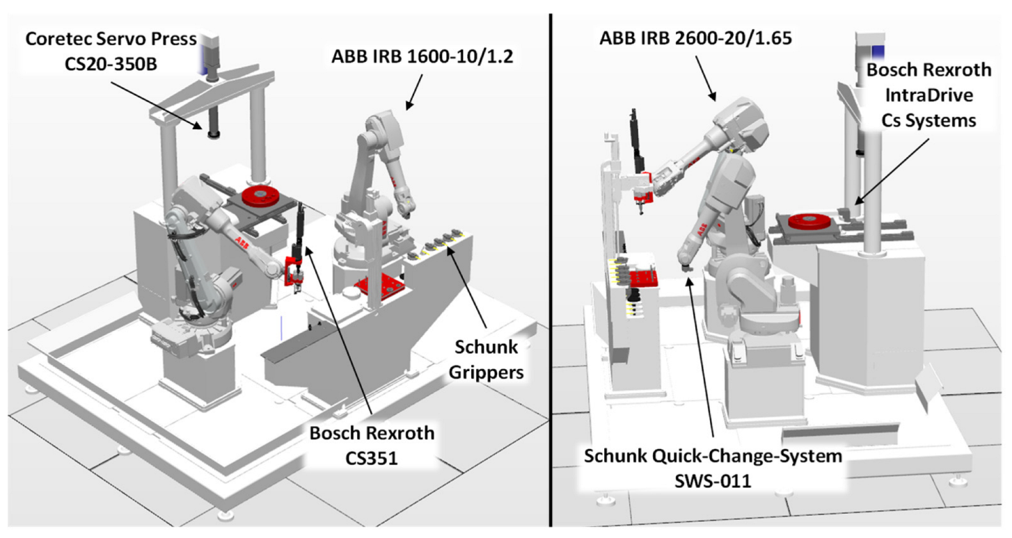
The robotic assembly cell includes two ABB industrial robots working in the same workspace. The aim of the cell is to mount fasteners and bearings on a basement resembling the case of a gearbox. The basement is placed on a Cartesian positioning table that is translated by two linear axes. The table can arrange the basement in different positions under an electric press, that is activated when pins or bearings must be pressed in their seats. Custom-designed punches are used depending on the object that must be pressed: they are brought in the right position by a robot and locked on the press due to its fast tool changer interface.
The two robots in the cell are equipped with different tools. IRB 1600-10/1.2 (Robot1) mounts a tool changer, which is used to lock the appropriate gripper depending on the object that has to be picked and then placed in the basement. Five Schunk grippers are provided belonging to two different families: the PNG-plus 80-1, which includes parallel grippers, and the PNZ-plus 80-1 family, which is a three-finger centric gripper. In particular, two parallel grippers are used to pick and place pins and handle punches, while three centric grippers are used to pick up bearings.
IRB 2600-20/1.65 (Robot2) mounts an electric, torque-controlled screwer from Bosch Rexroth. It picks the fasteners from their holder and screws them on the basement.
The system is coordinated by a Beckhoff Embedded PC CX5140 PLC equipped with Intel Atom quad-core processor. An EtherCAT fieldbus connects the devices in the cell and is responsible for the I/O signals connections.
A list of the main hardware components present in the cell is given in
Table 1.
The virtual model of the cell was created starting from a 3D representation realized in SolidWorks, including both the models used to design the components and models provided by the manufacturers of the devices (
Figure 4). Then, the geometry was imported into RS. This is then followed by a standard workflow, which includes the definition of movable devices, known as mechanisms, used in the specific case for the press, positioning table and grippers.
4.2. Communication Pattern between PLC and Cell Devices
The role of the PLC is to coordinate the activity of the robots and the devices included in the cell. According to the proposed approach, in the RS virtual model, a dedicated SC is created for each physical device. The SC represents the behavior of the physical asset being represented recurring to the functionalities provided by RS. However, the interface of the SC in terms of exchanged signal must be equal to the real device in order to permit a real VC of the cell.
A communication pattern was defined between the PLC and the other devices by means of a standardized set of signals, which are summarized in
Table 2. The reported signals represent a minimum core set to guarantee an efficient interaction between the PLC and the cell devices.
The actions performed by the robots and the devices in the cell were subdivided in elementary procedures, which are combined to perform more complex tasks. The PLC elaborates the required sequence of operations, the possible simultaneity of the actions according to the general assembly task of the cell, and the space-sharing constraints. Therefore, the PLC is in charge of sending identifiers of the procedures to be executed to cell devices, which were named as procedureNumber in case of manipulators and programNumber for the press. For the X-Y axes of the positioning table, the numeric value of the coordinate to be reached, i.e., the targetPosition, is provided. Finally, the communication pattern was completed with additional error signals in order to guarantee the required safety and robustness in industrial implementations.
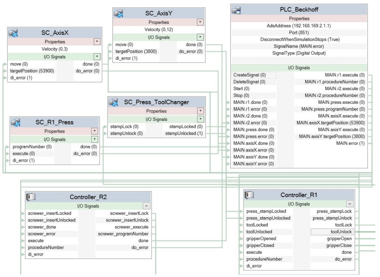
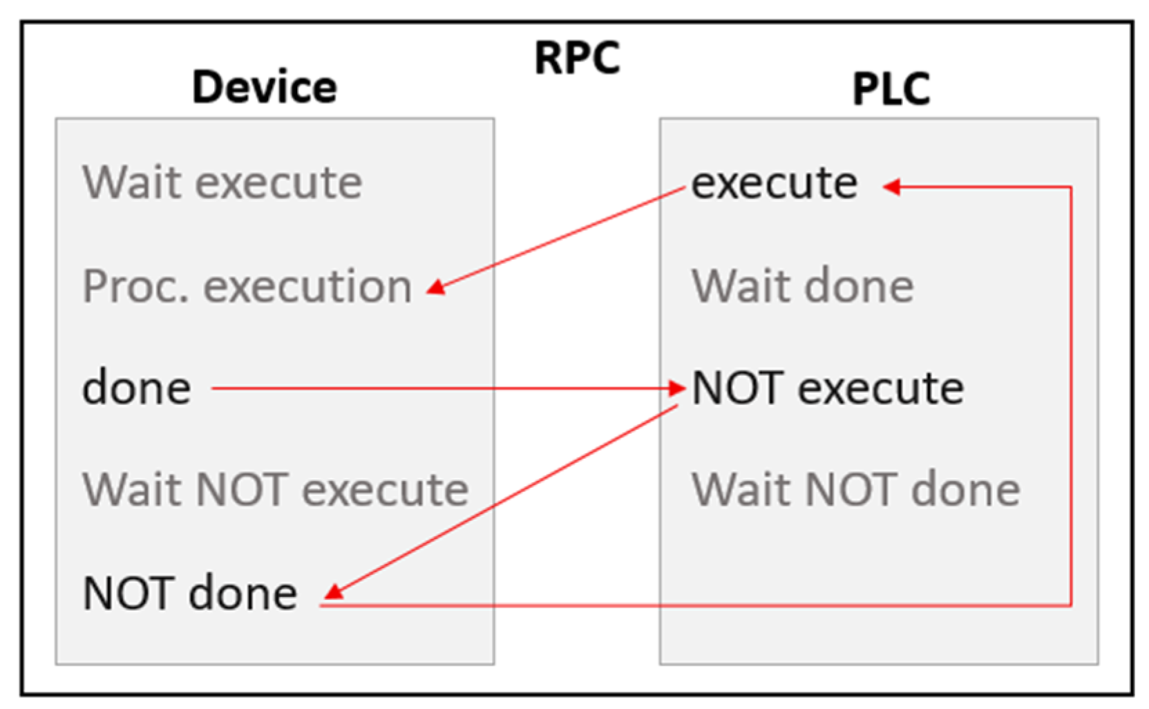
Figure 5 shows the appearance of PLC_Beckhoff SC connected to the cell devices, as the configuration stage of the cell is completed according to the signal pattern explained above. The signal exchange is based on a simple remote procedure call (RPC), i.e., a client–server interaction implemented via request–response messages. This pattern is able to safely manage complex scenarios in a standardized manner.
In practice, as depicted in
Figure 6, an operation is activated by the execute signal, and it gives feedback when activity ends by the done signal. Once the PLC has received the done signal, it resets the execute signal. Finally, the device resets the done signal as soon as it receives the information that the execute signal has been reset.
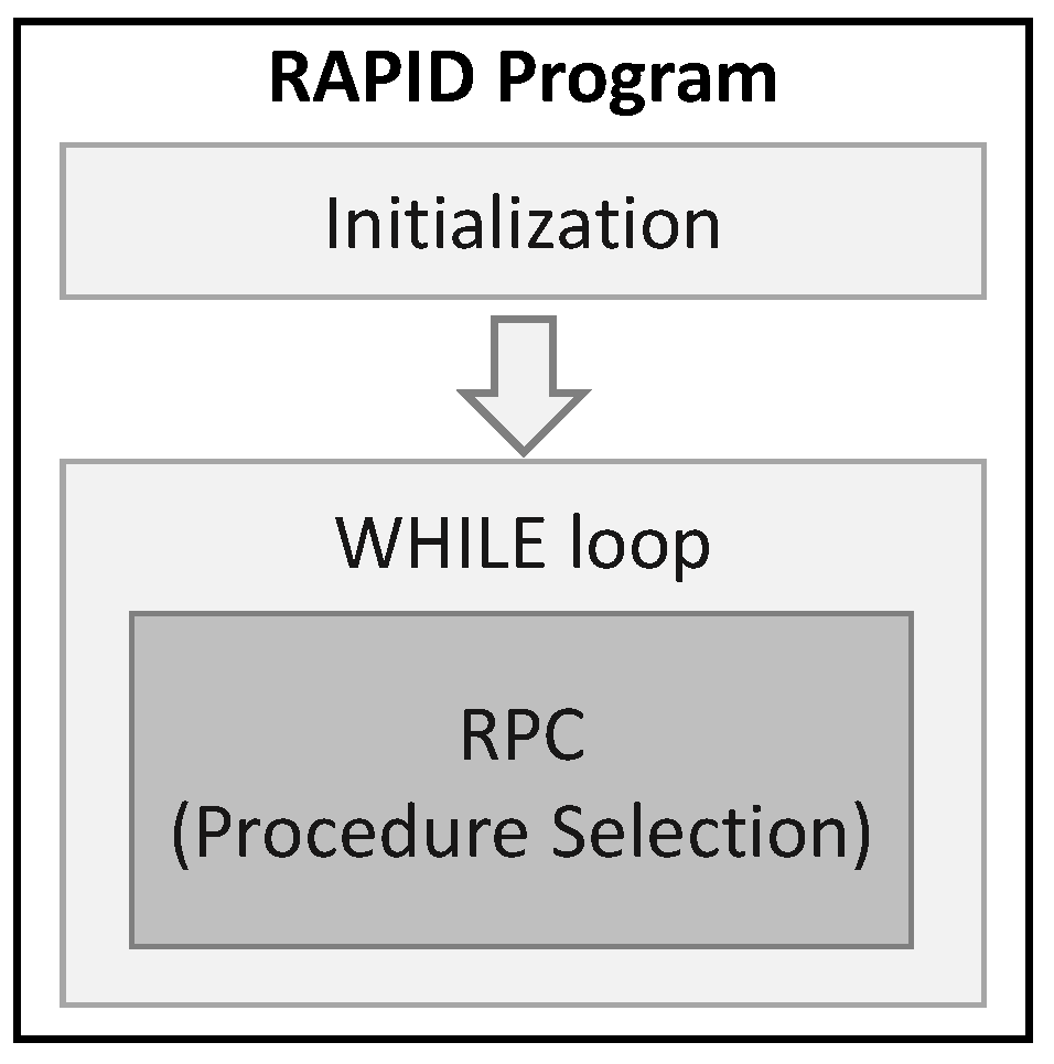
The same logic is applied to devices and robots, leveraging respective controllers’ codings means to handle the signals’ exchanges. For instance, in the specific case of an ABB robot, the RPC scheme is managed by a main loop operating in the RAPID code, i.e., the code running in the robot controller. As shown in
Figure 7, the robot acts as any other device: it receives an execute command from the PLC and it returns a done signal when the requested procedure is finished. As reported in the following pseudocode (Algorithm 3), the algorithm running on the robot controller includes a standard
Main section with a loop implementing the RPC pattern. The code ensures the management of the exchanged signals and the invoking of the desired procedure according to the value of the
procedureNumber.
| Algorithm 3 Main section with loop for RPC pattern |
Main()
in: signal procedureNumber; signal execute
out: signal done; signal do_error
constant: integer procedure identifier N_SZ_ObjectHolder
integer procedure identifier N_SZ_ToolHolder
…
1: Initialization ▷ Initialize variables
2: while true do ▷ Loop continuously
3: done ← 0 ▷ Reset done signal
4: while execute ≠ 1 do ▷ Wait until execute signal is true
5: end while
6: case procedureNumber of ▷ Call specific robot procedure
7: N_SZ_ObjectHolder: SZ_ObjectHolder
8: N_SZ_ToolHolder: SZ_ToolHolder
9: … ▷ Put other robot procedures here
10: others:
11: do_error ← 1 ▷ Unknown procedure number
12: end case
13: done ← 1 ▷ Set done signal
14: while execute ≠ 0 do ▷ Wait until execute signal is false
15: end while
16: end while |
Other code sections are then implemented to detail the action required by the specific operation procedure, such as a joint movement, gripper attaching, object grabbing, etc. Such procedures were defined according to the subdivision of the robot tasks in elementary operations accomplished in the initial design phase of the assembly process.
4.3. PLC Programming
The SFC graphic language, defined in the international standard IEC 61131-3, has been chosen as PLC programming means for its suitability to visualize conditional procedures as typically happens in industrial applications. Moreover, this language is easy to understand, as some basic interpretation rules are provided and can be combined with other PLC programming languages.
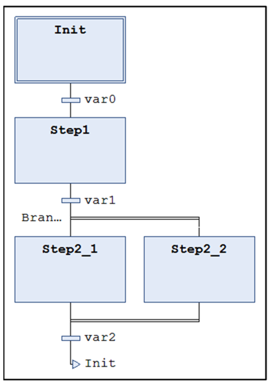
In
Figure 8, a simple diagram is shown as an example to recall the basics of SFC. The Init block with the double outline is the entry point of the program. The little rectangle below, linked by a vertical line, represents a transition, i.e., a step forward in the graph execution flow; the related condition is pointed out by the label beside it. Until the transition condition is not verified, the program cyclically executes the code included in the specific block. When the condition expressed in the label is met, the execution of the program will pass to the next block, and so on. In the SFC, it is also possible to make the program execute two or more blocks in the same cycle, using a parallel branch. In the example shown in
Figure 8, after var1 has become true, Step2_1 and Step2_2 are both cyclically executed until the variable var2 becomes true. Finally, the arrow indicates a jump, meaning that the program execution is brought back to the block named as the label next to the arrow.
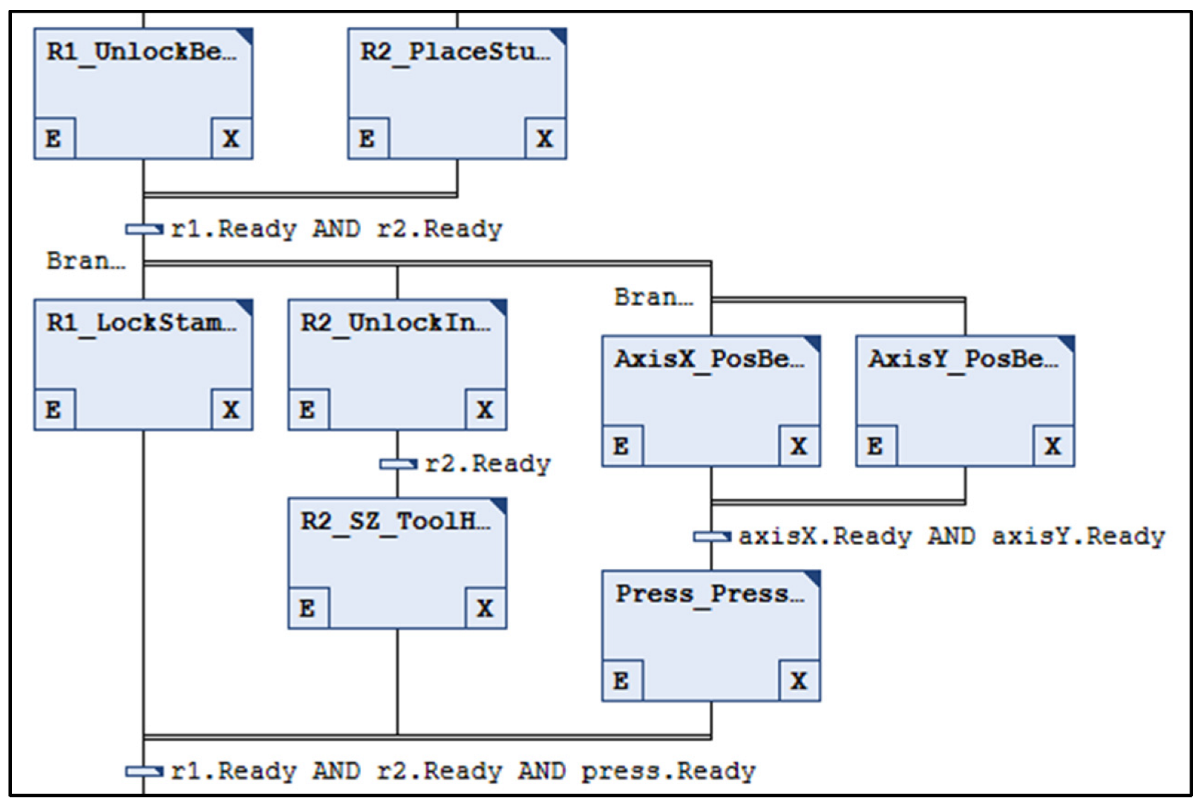
In the robotic assembly cell test case, the SFC programming language has been employed to program the PLC.
Figure 9 reports a portion of the program to show the logic used to build it. Each block of the diagram corresponds to an operation of a certain device. The features of the SFC, i.e., parallel branches, allowed the activities, which must be performed at the same time, to be managed. For instance, AxisX and AxisY are supposed to be moved simultaneously in order to reach the target position of the table in the minimum amount of time. On the contrary, the press must be actuated only when the table reaches the target position, as required by the sequential constrain that is expressed by the transition condition named Ready.
5. Tool Validation and Results
The implemented integration between RS and TC was tested against the possibility to perform an effective VC of the cell. In particular, a series of assembly tasks were defined and simulated to identify the optimal assembly sequence for the proposed gearbox assembly task. For a better understanding of the executed work, a video showing the VC of the as-sembly cell is provided in the
Supplementary Material Section. In the video, the PLC and the virtual cell in RS are displayed side-by-side. In particular, an example of the assembly sequence was shown that has been recorded to illustrate the command activation from the PLC and the variation in the signals’ statuses, both in TC and RS.
The whole gearbox assembly task was subdivided in a list of elementary operations to be arranged in proper sequences. The examples of considered operations include:
LockInsert: locate a pushing insert in the press and attach it to the end effector;
UnlockInsert: detach an insert from the press and locate in the magazine;
PickBearing: grab a bearing with a gripper;
PlaceBearing: locate a bearing on its assembly position;
ScrewStud: screw a threaded stud by the torque-controlled screwdriver.
Following the architecture described in the previous section, the code in the controllers of the robots and other cell devices is in charge of activating the operations according to the signals received by the PLC. The actual sequence of operations is determined by the PLC program. Therefore, several PLC programs, including different sequences of operations were generated and tested.
From the experimental activity, it emerges that, in the virtual environment, various aspects can be verified and optimized. At first, the appropriate sequence of actions and the correctness of signals exchange between PLC and controllers must be verified and optimized. Therefore, PLC program robustness is verified and tested in normal operating conditions as well as in fault events caused by errors, safety alarms or unexpected situations.
The reachability of the desired locations, the quality and fluency of the movements, the absence of collisions, as well as the overall time required to accomplish the tasks are other significant tasks that can be verified before commissioning the real cell to ensure a successful result.
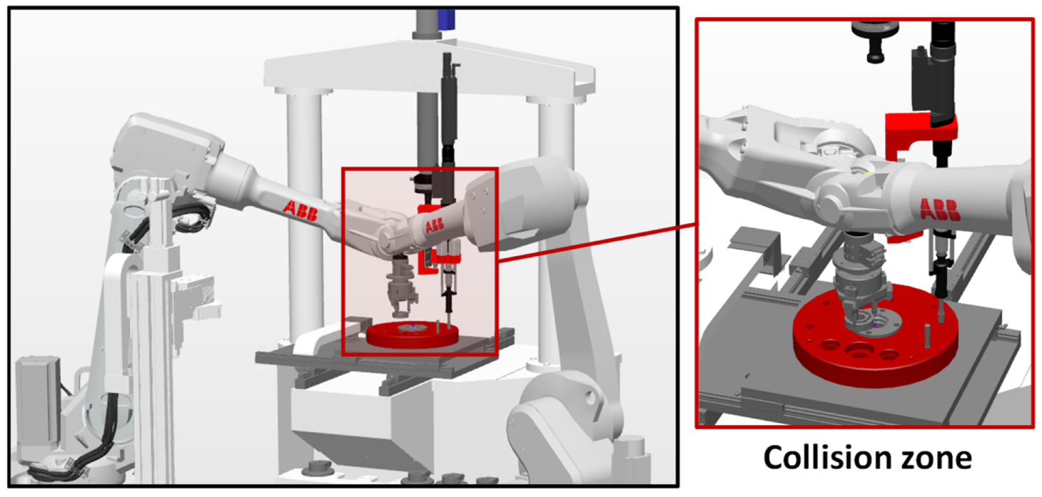
Finally, the VC was analyzed as a means to optimize the sequence of the operations coordinated by the PLC. The absence of collisions between two robots sharing their workspace (see
Figure 10), the interchangeability of the single assembly operation, and the possibility to parallelize actions performed in different zones of the cell make the solution space of all of the possible operating sequences quite vast. This opens up to the possibility of optimizing the order of the operations requested of the two robots and other devices in order minimize the overall accomplishing time.
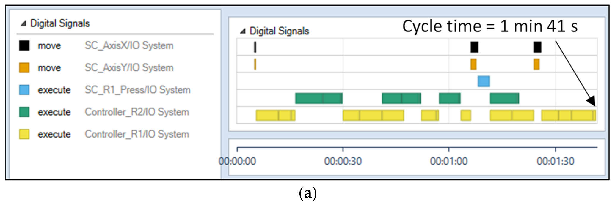
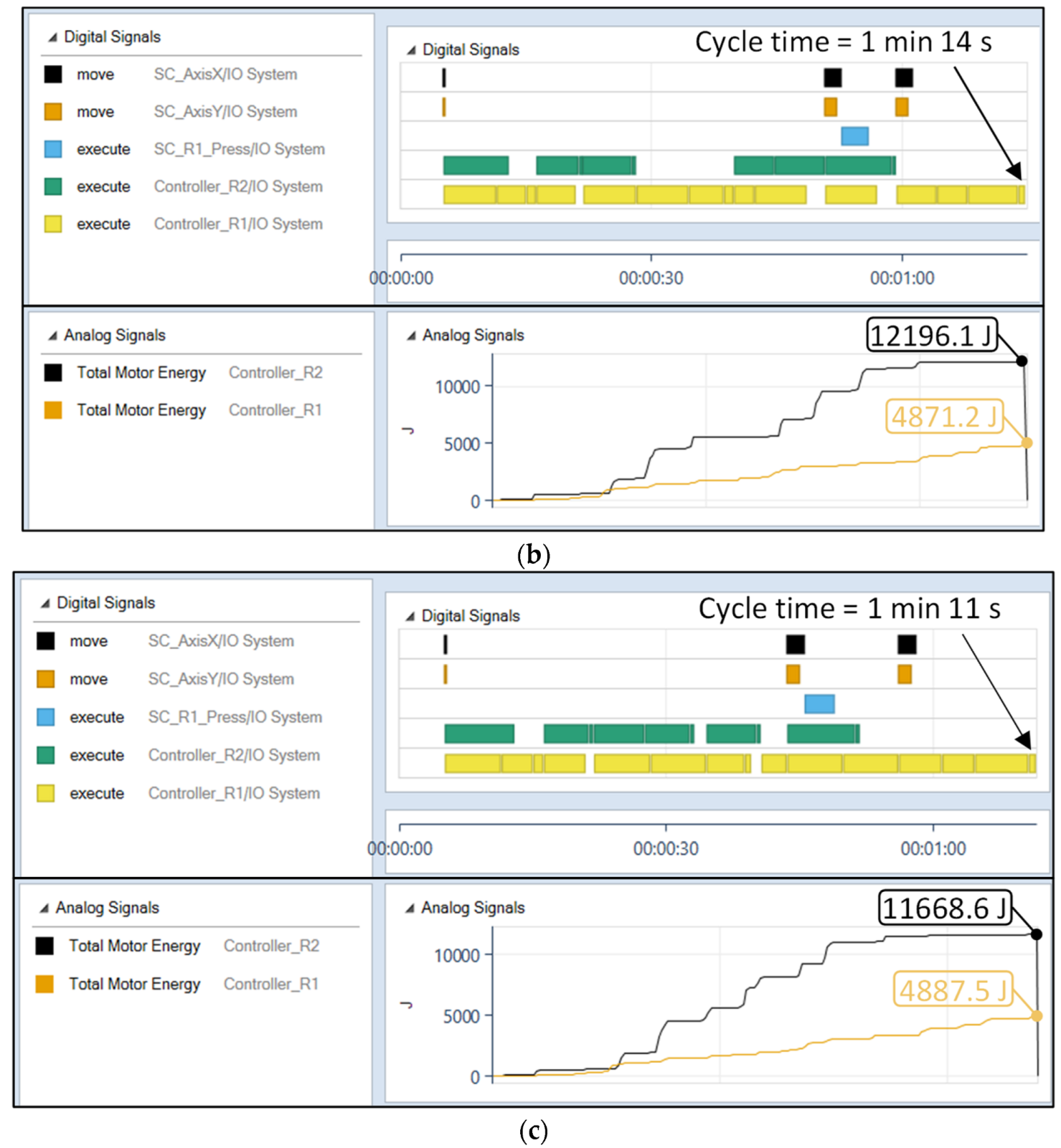
Figure 11 reports an example of tests performed to identify the optimal sequence permutation of the same list of operations. In the figure, three different sequences are reported, respectively, assigned to the positioning table axes, the press, and the two robots. The colored bars show the activation times of the devices, as highlighted by the legends in the figures. It is evident how some operations can be parallelized, while in other moments, the operability of a device must be suspended until specific actions are completed. However, looking at the three different operation sequences it emerges that different levels of operations can simultaneously be reached. For instance, in the reported case, (a) the operations performed by Robot 1 (yellow band), which is the device with a major workload in the cell, are fragmented, and the overall cycle time is degraded due to frequent downtime periods.
The improved sequences of operations leads to an overall cycle time reduction of 30%, i.e., from the initial 101 s to an intermediate sub-optimal solution (i.e., 74 s, case (b)) and finally, to a saving of more seconds (i.e., 71 s, case (c)). As a further demonstration of the VC tool potentialities, the same picture reports the RS estimation of the total energy required by the motors of the robots during the entire work cycle, comparing the sub-optimal and the optimal sequences. It can be observed that the last case provides an overall reduction in energy consumption of 3% (i.e., from 17,067 J to 16,556 J). It is worth noting that, based on the declared design intents, any other output made available by RS simulation can be utilized as a performance index in the optimization study.
As a further development, an additional optimization algorithm may be foreseen to generate candidate sequences to be sent to the PLC, and then automatically elaborated in the proposed VC system to check for the resulting performance, such as collision avoidance and cycle time. Such a system would be helpful in searching for optimal solutions in an automatic, faster and more reliable way.
6. Conclusions
VC technology is an efficient tool for companies to be competitive since it allows the commissioning activities of a production system to be anticipated during the design phase, offering the chance to find errors and improve the project when engaged investments are still relatively low. On the other hand, mechatronic systems are often complex and composed by devices from different producers, each one recurring for a different software platform. Consequently, tools that validate and verify the interactions of different controllers codes become strategic in the VC perspective. In this context, the tools that enable the communication between two common software in the industrial automation panorama, RS and TC, were proposed. They allow a signal exchange to be easily established between PLC and other devices, as is the case in real systems. The tool demonstrated an effective performance, and the connection was solid and reliable. The main outcome is that both PLC and robot programs can be checked concurrently and optimized before being implementation in the physical system. The effect of any change at code level can be tested on the whole system in a single environment without the need to simplify or idealize the parts behavior.
Beyond these encouraging results, future work could be focused on the improvement of the working performance of the application, aiming for a more efficient communication code to reduce latency. Moreover, since both RS and TC are proprietary solutions that only comprise vendor-specific devices, the presented approach can either be replicated with other commercial platforms or even extended to general-purpose platforms, where products from many vendors can be simulated.


 ,
, 


