Article

Vibration and Wave Analyses in the Functionally Graded Graphene-Reinforced Composite Plates Based on the First-Order Shear Deformation Plate Theory

1
Department of Architectural Engineering, North China Institute of Aerospace Engineering, Langfang 065000, China
2
School of Civil Engineering, Guangzhou University, Guangzhou 510006, China
3
College of Mechanical Engineering, Zhejiang University of Technology, Hangzhou 310014, China
*
Authors to whom correspondence should be addressed.
Appl. Sci. 2022, 12(6), 3140; https://doi.org/10.3390/app12063140
Submission received: 11 February 2022 / Revised: 12 March 2022 / Accepted: 14 March 2022 / Published: 18 March 2022

Abstract

:
Graphene platelets (GPLs) can be used to enhance the mechanical and electrical properties of the matrix material, which efficiently determines and improves the dynamic behavior in composite structures. Based on the first-order shear deformation theory, this paper investigates the vibration and wave problems in a functionally graded graphene-reinforced composite plate. The composite plate is composed of the polymer matrix reinforced with GPLs that are dispersed along the thickness direction, following four kinds of functionally graded patterns. The governing equation of dynamic problems in the composite plate can be described in the state space formulation, and be solved using the method of reverberation-ray matrix (MRRM). Unlike the traditional state space method, this method is unconditionally stable due to introducing the dual coordinates, which can inherently avoid the numerical instability. After a validation study to verify the present analysis, a parametric study is conducted to analyze the effect of weight fraction, size and distribution patterns of the reinforments, as well as the boundary conditions and aspect ratios on the dynamic behaviors of the composite plate, hence providing a better way to achieve improved dynamic resistances of the GPLs composite plates.

1. Introduction

Since its discovery in 2004 [1], graphene has gained huge amounts of attention from both research and engineering communities due to its superior mechanical, electrical and thermal properties [2,3,4]. Compared to carbon nanotubes (CNTs), graphene has a much larger surface area and comparable properties, and soon becomes an emerging reinforcement in composites [5]. Rafiee et al. [6] found that the graphene/epoxy composite exhibits significantly higer tensile strength and Young’s modulus than the epoxy composites reinforced with the same amount of CNTs. Later, other studies also revealed that the buckling behavior of the graphenen/epoxy composite is vastly superior to the composites with CNTs reinforcements [7,8].
Recently, Luong et al. [9] developed a pioneering new method of producing graphene in bulk—flash Joule heating, which can zap any inexpensive source of solid carbon, from food scraps to car tires, and turn it into graphene in less than one second, and will open up various new applications in engineering. Its outstanding tensile strength, Young’s modulus, buckling behavior and a much larger surface area of graphene, together with the avent of bulk producing method [9], enable it to become a most promising reinforcement material. As a consequence, the polymer composites reinforced with graphene nanofillers have attracted extensive research interest [10].
Functionally graded materials (FGMs) consist of two or more materials, in addition to the continuous variation in both composition and properties along certain directions. The material properties of FGMs can be tailored to meet the requirements in various extreme working conditions. Recently, the functionally graded graphene platelets (FG-GPLs) reinforced composites have attracted academic interest. Wu et al. [11] analyzed the thermal buckling and post-buckling of FG-GPLs reinforced plates. Based on the Chebyshev–Ritz method, Yang et al. [12] studied the buckling and free vibration problem in FG-GPLs reinforced porous nanocomposite plates. Based on the high-order shear deformation theory, Shen et al. [13] performed analysis on the nonlinear vibration of FG-GPLs reinforced composite beams in thermal environments, Safarpour et al. [14] studied the bending and vibration response of FG-GPLs reinforced rectangular plates for different substrates and thermal conditions both theoretically and numerically, and Wang and Ma [15] focused on the effect of thickness stretching on static and dynamic responses of FG graphene-reinforced plates. However, the higher-order theory is more exact and complicated; there is no experimental evidence that it is necessary to adopt the higher-order theory in FG-GPLs composites [16]. That is, it is sufficient to use the classical plate theory (CPT) or first-order deformation theory (FSDT) to analyze the graphene-reinforced composites.
This paper analyzes the dynamic behaviors in the functionally graded plates reinforced with GPLs using the first-order shear deformation theory. The improved Halpin-Tsai micromechanical model and traditional rule of mixture are utilized to determine the effective material properties. The governing equations are constructed in the state space, and then solved using method of reverberation-ray matrix (MRRM) [17,18]. With special formulation, MRRM can avoid numerical instability inherently even for high frequencies or big wavenumbers [19,20]. Then a parametric study is conducted, the effects of the weight fraction, nanofiller size, distribution patterns of GPLs, the boundary conditions and aspect ratios on the dynamic behaviors of the FG-GPLs plates are studied in detail in the numerical examples.

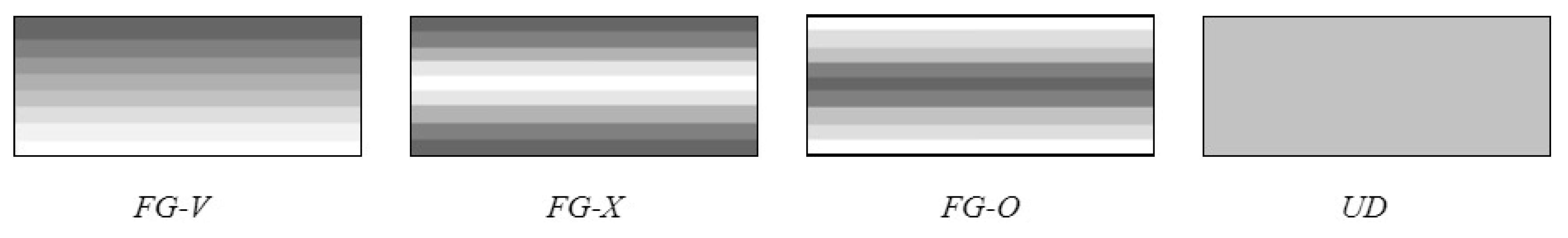
2. FG Composite Plates Reinforced with GPLs

Consider a functionally graded graphene platelets (FG-GPLs)-reinforced composite plate in a coordinate system ( 0 x a , - y , - h / 2 z h / 2 ,), which is shown in Figure 1. For the wave propogation problem, the plate is finite in the x and z-axis, infinite in the y-axis, and made from a composite material comprising an isotropic matrix with GPLs reinforcement whose mixing ratio may vary along the z-axis (functionally graded materia, FGM).
According to the modified Halpin-Tsai micromechanics model [6], the effective Young’s modulus of FG-GPLs reinforced composite can be well approximated by
E = 3 8 1 + ξ l η l V G 1 η l V G E M + 5 8 1 + ξ w η w V G 1 η w V G E M
where η l = E G / E M 1 E G / E M + ξ l , η w = E G / E M 1 E G / E M + ξ w , E G and E M represent the Young’s moduli of GPLs and polymer matrix, respectively, and V G represents the GPL volume fraction. The scaled parameters ξ l and ξ w denote the effects of both the geometry and size of GPL nanofillers, and can be expressed as
ξ l = 2 a G / t G , ξ w = 2 b G / t G
in which a G , b G , t G are the length, width and thickness of GPL nanofillers, respectively.
However the modified Halpin–Tsai model cannot deterimine the mass density and Poisson’s ratio of composite materials. By using the rules of mixture, the Poisson’s ratio and density of the nanocomposites can be obtained as
ν = ν G V G + ν M ( 1 V G )
ρ = ρ G V G + ρ M ( 1 V G )
where ν G , ρ G and ν M , ρ M represent the Poisson’s ratios, densities of GPLs and polymer matrix, respectively.
In this paper, four different GPLs distribution patterns are considered, named FG-V, FG-X, FG-O and UD [11,12], as schematically depicted in Figure 2, and can be expressed as
FG - V :   V G ( z ) = V G ( 1 + 2 z / h ) FG - X :   V G ( z ) = V G 4 | z | / h FG - O :   V G ( z ) = V G ( 2 4 | z | / h ) UD :   V G ( z ) = V G
where z [ - 0.5 h , 0.5 h ] , and V G is the total volume fraction of GPLs, which can be determined by the total weight fraction of GPLs W G ,
V G = W G W G + ( ρ G / ρ M ) ( 1 W G )

3. Theoretical Formulations of Composite Plates

3.1. Governing Equations in the State Space

Based on the first-order shear deformation plate theory (FSDT), the displacements can be described as
u 1 ( x , y , z , t ) = u ( x , y , t ) + z φ x ( x , y , t )
u 2 ( x , y , z , t ) = v ( x , y , t ) + z φ y ( x , y , t )
u 3 ( x , y , z , t ) = w ( x , y , t )
where t is the time, u 1 , u 2 , u 3 are the displacements at any point ( x , y , z ) , u , v , w are the displacements of the point ( x , y , 0 ) on the mid-plane, φ x and φ y are the rotations of the normal about the y- and x-axis, respectively.
The stress–strain relationship is given by the following expressions,
[ σ x x σ y y τ x y ] = [ Q 11 Q 12 0 Q 21 Q 22 0 0 0 Q 66 ] [ u , x + z φ x , x v , y + z φ y , y u , y + v , x + z ( φ x , y , + φ y , x ) ]
[ τ x z τ y z ] = κ [ Q 44 0 0 Q 55 ] [ w , x + φ x w , y + φ y ]
in which the shear correction coefficient κ is assumed to be 5/6 for FSDT by Whitney and Pagano [21]. The position-dependent elastic constants Q i j are described as
Q 11 = E 11 ( z ) 1 ν 12 ν 21 , Q 22 = E 22 ( z ) 1 ν 12 ν 21 , Q 12 = ν 12 E 22 ( z ) 1 ν 12 ν 21
Q 44 = G 13 ( z ) , Q 55 = G 23 ( z ) , Q 66 = G 12 ( z )
The governing equations of motion for the FG-GPLs reinforced plate [21] can be achieved
N x , x + N x y , y = I 1 u ¨ + I 2 φ ¨ x
N x y , x + N y , y = I 1 v ¨ + I 2 φ ¨ y
Q x , x + Q y , y = I 1 w ¨
M x , x + M x y , y Q x = I 2 u ¨ + I 3 φ ¨ x
M x y , x + M y , y Q y = I 2 v ¨ + I 3 φ ¨ y
where the over dot represents partial derivative of time t. The stress or moment resultants and the inertia-related terms are defined by
( N x , N y , N x y , Q x , Q y ) = h / 2 h / 2 ( σ x x , σ y y , τ x y , τ x z , τ y z ) d z
( M x , M y , M x y ) = h / 2 h / 2 ( σ x x , σ y y , τ x y ) z d z
( I 1 , I 2 , I 3 ) = h / 2 h / 2 ρ ( 1 , z , z 2 ) d z
Using Equations (7)–(9) and (11), we can reconstruct Equation (10) in the state space form as
x Θ = Σ Θ = [ Σ 1 Σ 2 Σ 3 Σ 4 ] Θ
where Θ = [ u , v , w , φ x , φ y , M x , M x y , N x , N x y , Q x ] T is the vector, and the coefficient matrices Σ i (i = 1, …, 4) are given in Appendix A.
For the wave propagating along the y direction, the vector in the governing equations can be denoted in the following dimensionless form
Θ = [ u v w φ x φ y M x M x y N x N x y Q x ] = { h u ¯ ( ξ ) h v ¯ ( ξ ) h w ¯ ( ξ ) φ ξ ( ξ ) φ η ( ξ ) E M h 2 M ¯ ξ ( ξ ) E M h 2 M ¯ ξ η ( ξ ) E M h N ¯ ξ ( ξ ) E M h N ¯ ξ η ( ξ ) E M h Q ¯ ξ ( ξ ) } e i ( χ η ω t )
in which ξ = x / a , η = y / a , χ the wavenumber of the η direction and ω the circular frequency. Plugging Equation (13) into Equation (12), one obtains the dimensionless state space equation,
d d ξ Θ ¯ = Σ ¯ Θ ¯ = [ Σ ¯ 1 Σ ¯ 2 Σ ¯ 3 Σ ¯ 4 ] Θ ¯
where Θ ¯ = [ u ¯ , v ¯ , w ¯ , φ ξ , φ η , M ¯ ξ , M ¯ ξ η , N ¯ ξ , N ¯ ξ η , Q ¯ ξ ] T , and the submatrices of the coefficient matrix Σ ¯ are listed in Appendix B.
On the edges of ξ = 0 , 1 ( x = 0 , a ), we take three cases for example: simply supported (S), clamped (C), or traction-free (F), which can be described as,
w ¯ = φ η = M ¯ ξ = N ¯ ξ = N ¯ ξ η = 0 ( S )
u ¯ = v ¯ = w ¯ = φ ξ = φ η = 0 ( C )
M ¯ ξ = M ¯ ξ η = N ¯ ξ = N ¯ ξ η = Q ¯ ξ = 0 ( F )
The transfer matrix method, as one of the most efficient approaches dealing with the matrix equation, is usually adopted to seek the solution of state space Equation (14) [22,23,24]. However, when the product of the frequency and length is large enough [25,26,27], it will encounter the inherent numerical instability. So, in this work, the method of reverberation-ray matrix (MRRM) is utilized in what follows to overcome this problem.

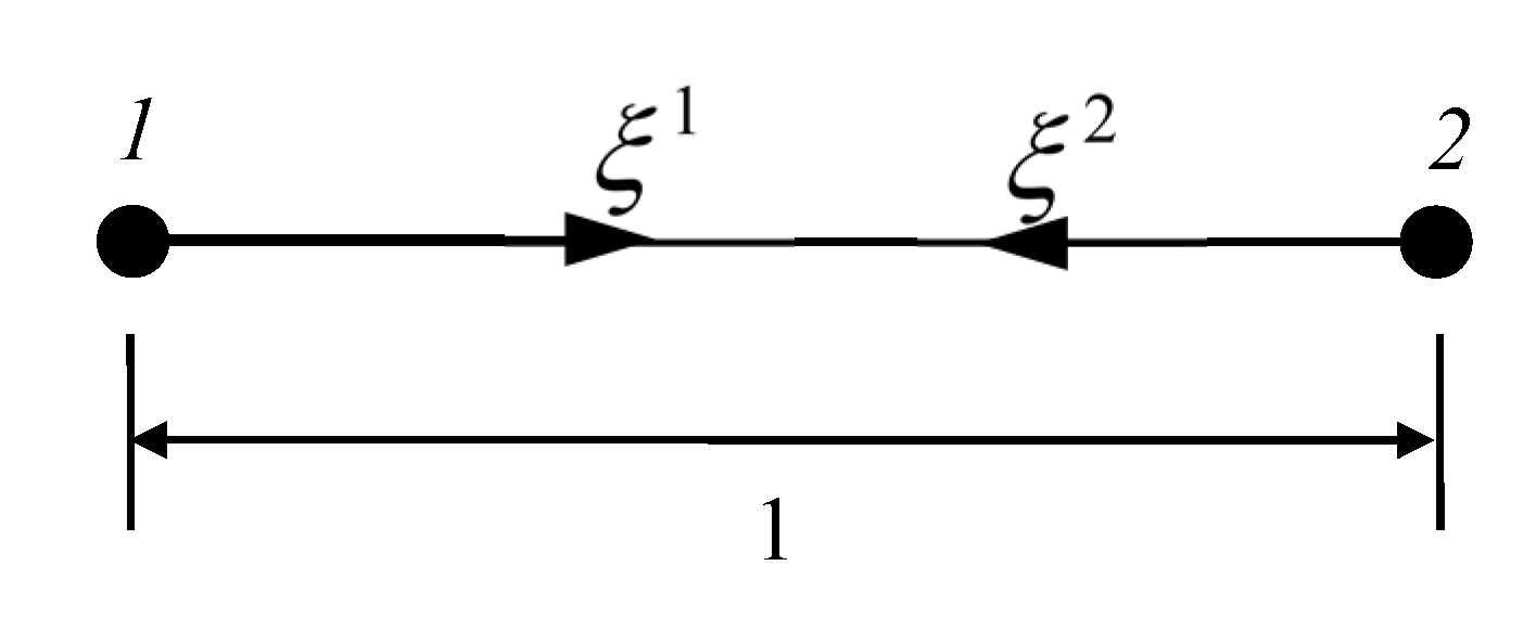
3.2. MRRM Formulation

Owing to the constant state matrix Σ ¯ , we can describe the general solution of Equation (14) as
Θ ¯ ( ξ ) = Ψ exp ( Λ ξ ) γ
AS stated in the eigenproblem in alignment of molecules [28], Λ = diag ( λ 1 , λ 2 , , λ 10 ) is a diagonal matrix with λ i (i = 1,2,…,10) being the eigenvalues of the coefficient matrix Σ ¯ , Ψ = [ Ψ 1 , Ψ 2 , Ψ 3 , , Ψ 10 ] are the eigenvectors, and γ are the wave amplitude vectors. Due to the physical meaning of wave propagation, the coefficient matrix Σ ¯ is a Hamiltonian matrix, so the eigenvalue matrix can always be separated as follows,
Λ = [ Λ + 0 0 Λ ]
where Λ + comprises five eigenvalues with positive real part or positive imaginary part for pure imaginary, while Λ contains the remaining five eigenvalues, and Λ = Λ + . Similarly, we can divide the wave amplitudes γ to γ = [ ( γ + ) T , ( γ ) T ] T . So, the solution can be rewritten as
Θ ¯ ( ξ ) = [ Ψ + Ψ ] [ exp ( Λ + ξ ) 0 0 exp ( Λ ξ ) ] { γ + γ }
Before using MRRM, we should introduce the dual local coordinates first. For one element problem shown in Figure 3, the two local axes ξ 1 , ξ 2 are in opposite directions.
In the two local coordinates ξ 1 and ξ 2 , the solution to Equation (18) can be rewritten as
Θ ¯ 1 ( ξ 1 ) = [ Ψ + 1 Ψ 1 ] [ exp ( Λ + 1 ξ 1 ) 0 0 exp ( Λ 1 ξ 1 ) ] { γ + 1 γ 1 }
Θ ¯ 2 ( ξ 2 ) = [ Ψ + 2 Ψ 2 ] [ exp ( Λ + 2 ξ 2 ) 0 0 exp ( Λ 2 ξ 2 ) ] { γ + 2 γ 2 }
According to 1 ξ 1 = ξ 2 in the dual local coordinate system in Figure 3, the relationship between Θ ¯ 1 and Θ ¯ 2 can be derived as
Θ ¯ 1 ( 1 ξ 1 ) = T f Θ ¯ 2 ( ξ 1 )
where T f is the transformation matrix. Plugging Equation (20) into Equation (14) yields the following relationships [29]
Σ ¯ 2 = T f Σ ¯ 1 T f 1 ,   Λ 2 = Λ 1 ,   Ψ 2 = T f Ψ 1
Combining Equations (19)–(21) yields
{ γ + 1 γ + 2 } = [ 0 exp ( - Λ + 1 ) exp ( Λ 1 ) 0 ] { γ 1 γ 2 } = P { γ 1 γ 2 }   or   a = P d
where P is the phase matrix. By dividing the unknown constants into two groups, exponential operation of large numbers is avoided in the phase matrix, which assures the unconditional numerical stability. Using Equation (19), the boundary conditions on the edges ξ = 0 , 1 are
D 1 γ 1 = S 1 γ + 1 ( at ξ 1 = 0 ) ,   D 2 γ 2 = S 2 γ + 2 ( at ξ 2 = 0 / ξ 1 = 1 )
or reformulated in a combined form
[ D 1 0 0 D 2 ] { γ 1 γ 2 } = [ S 1 0 0 S 2 ] { γ + 1 γ + 2 }   or   D d = S a
where the scattering matrix D , S are determined by the boundary conditions [30]. For simply supported, clamped or free edges, their expressions are summarized in Appendix C. Combining Equations (22) and (24), we can derive the characteristic equation of the wave propagating in the FG-GPLs reinforced composite plate,
| D S P | = 0
from which the dispersion relationship between the frequency and wavenumber can be derived. Unlike the solving process in Reference [31], we use | D S P | = 0 instead of | I D 1 S P | = 0 to avoid the inversion of matrix D, which may introduce numerical problem when | D | = 0 .

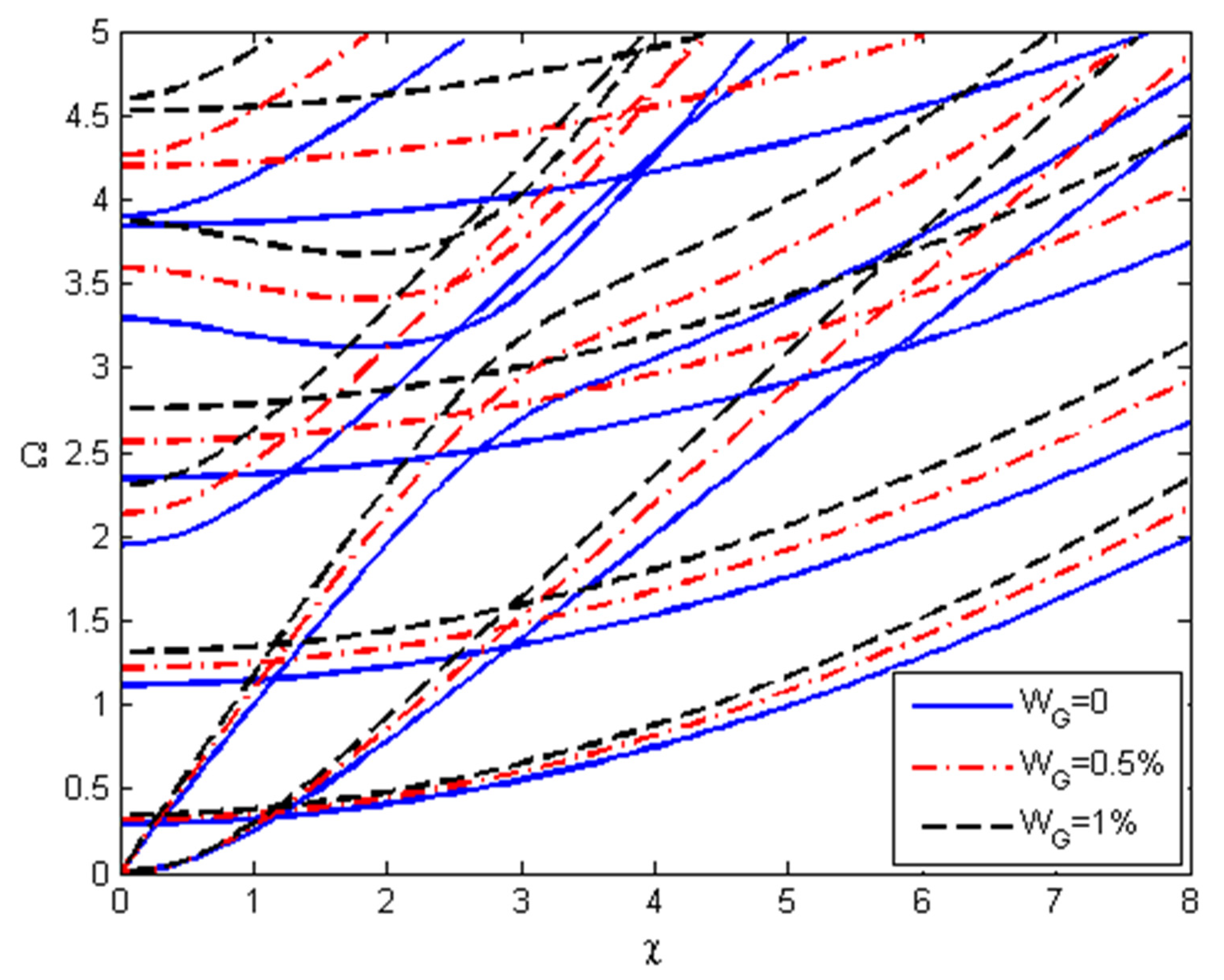
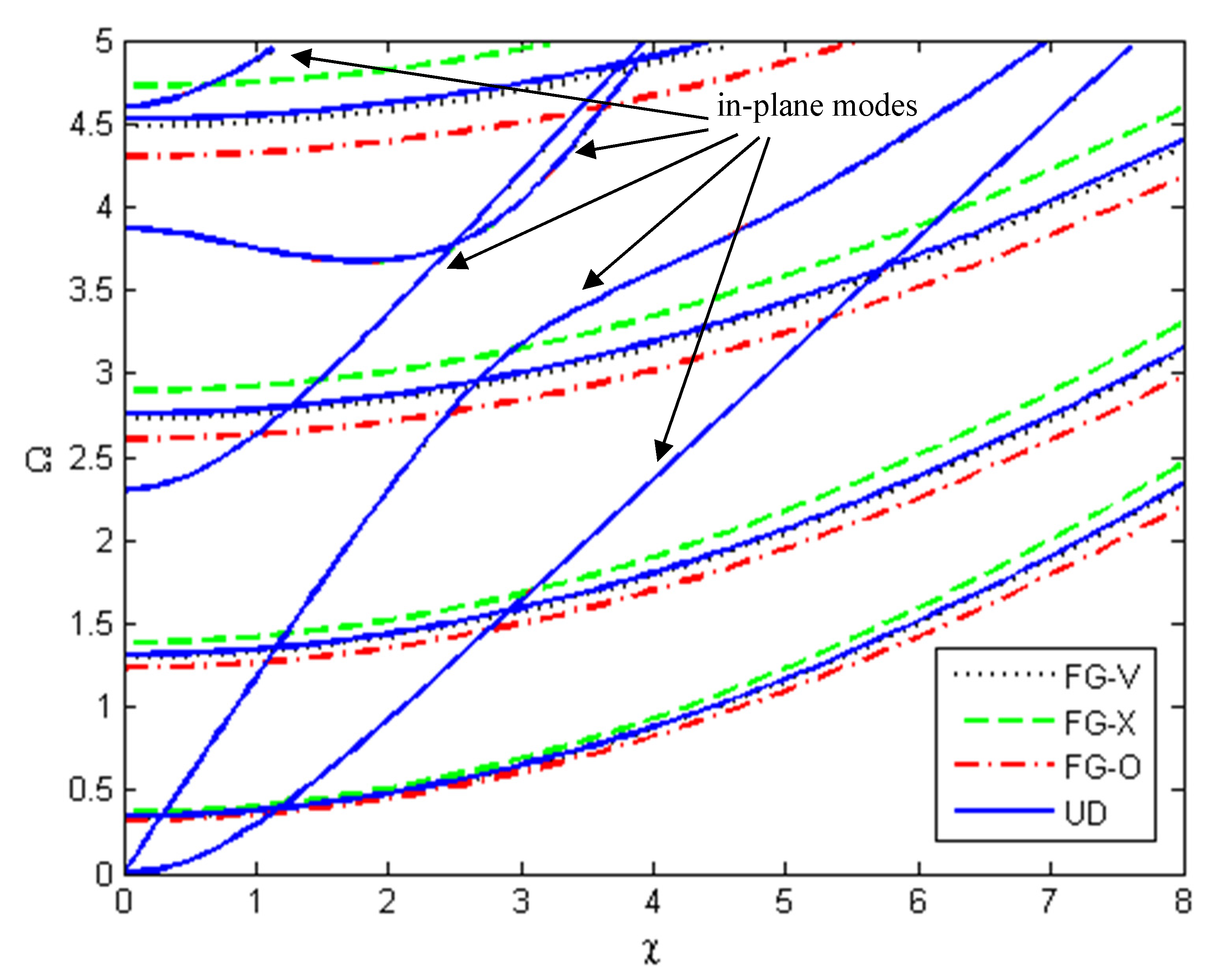
4. Results and Discussion

First, the free vibration of FGM square plates is analyzed to validate the present research. The square plates are made of aluminum oxide (ceramic) and Ti-6Al-4V (metal), with two opposite edges simply supported. The material properties, the ceramic variation and the plate size can be found in References [31,32,33,34]. The results of the classical plate theory [32], semi-analytical [33] and analytical results [34] based on the higher-order shear deformation plate theory are also included for comparison. Since the validation analysis has been performed in our former work [31], the numerical examples are omitted here for the sake of simplicity. As Table 1 in reference [31] shows, the results are in good agreement with those of other theories, which validates our formulation and programing.
Then we study the free vibration problem in the FG-GPLs-reinforced plates. In what follows, the FG-GPLs reinforced plates are made from a mixture of the polymer PMMA and GPLs with a length of a G = 2.5   μ m , width of b G = 1.5   μ m , and thickness of t G = 1.5   nm . The material properties of PMMA and GPLs are shown in Table 1. The effective material properties of the composite plates are determined by Equations (1)–(4). Unless declared otherwise, s = 0.1 , W G = 1 % , a G = 2.5   μ m , b G = 1.5   μ m , t G = 1.5   n m , the plate is simply supported at two opposite ends with FGM pattern UD used in Table 2, Table 3 and Table 4. The dimensionless frequency is
Ω = ρ M ω 2 a 2 / E M
Table 2 compares the first five natural frequencies of SSSS square plates for m = 1~5 with different GPLs weight fractions (WG = 0, 0.1, 0.5, 1%). For every m, the frequencies increase as the weight fraction rises. This can be expected as the increased GPLs content improves the stiffness of the plates substantially.
Table 3 and Table 4 are focused on the effect of GPLs shape on the natural frequencies of the SSSS square plates for m = 1~5 under free vibration. The influence of different shape ratios is investigated, including GPLs aspect ratio aG/bG and width-to-thickness ratio bG/tG. It can be observed from Table 3 and Table 4 that increasing aG/bG with a fixed bG/tG or raising bG/tG under a constant aG/bG, grows the natural frequencies of the square composite plates. A higher value of aG/bG represents a larger surface area, and a larger bG/tG indicates a wider graphene sheet. Hence, the bigger or wider GPLs can provide the better stiffening effect for the composite plates.
To better illustate the influence of different parameters on the wave spectra, Figure 4, Figure 5, Figure 6 and Figure 7 are presented. Unless stated otherwise, s = 0.1 , W G = 1 % , the plate is simply supported at ξ = 0 . 1 with FGM pattern UD used in all examples. The dimensionless frequency and wavenumber are Ω = ρ M ω 2 a 2 / E M and χ = k a , respectively.
Figure 4 investigates the effect of weight fractions on the dispersion spectra of GPLs reinforced plates. The frequencies always increase with the increasing weight fraction, so the dispersion curves will move upward as shown in Figure 4. For every mode, the blue solid branch for WG = 0 is the lowest, the red dot dash line for WG = 0.5% is middle, while the black dash line for WG = 1% is the highest.
Figure 5 shows the influences of different GPLs distribution patterns on the dispersion spectra of the FG plates. As demonstrated by the figure, the GPLs distribution patterns have little influence on the in-plane modes, while they have a considerable impact on the flexural modes [31]. For the same branch of the dispersion spectra, the red dot dash is the lowest (FG-O), the green dash (FG-X) is the highest, yet the blue solid (UD) and the black dash (FG-V) are quite close to each other. Compared with the other patterns, the FG-X plate has the highest frequencies. This is due to the symmetric configuration in the thickness direction. Meanwhile, the top and bottom surfaces with the maximum normal stress are GPLs rich and the neutral layer with the minimum normal stress is pure PMMA. This distribution pattern is the most effective since it makes better use of GPLs reinforcements and determines the higher bending stiffness. On the contrary, FG-O patterns performs the lowest frequency due to the weakest bending stiffness.
Figure 6 analyzes the effect of the boundary conditions on the dispersion spectra of the composite plates with different boundary conditions at ξ = 0 , 1 in which SS, CC and FF represent both edges, simply supported, clamped and free. As we can see, the boundary condition has little effect on the in-plane modes of the dispersion spectra, and the flexural modes are quite sensitive to the boundary conditons. Especially the first two black dash branches are unique for the FF plate, the corresponding branches for the SS and CC conditions are absent.
Figure 7 depicts the first four dispersion spectra of the composite plates with different aspect ratios (s = 0.1, 0.15, 0.2), which include two in-plane and two flexural modes. Similar to the phenomenon shown in Figure 6, the dispersion relations are insensitive to the aspect ratio for the two in-plane modes, while the aspect ratio noticeably affects the flexural modes. The frequency grows with the apsect ratio increases for the flexural modes. The in-plane mode branches go steeper, while the flexural mode branches become milder. Concluded from Figure 4, Figure 5, Figure 6 and Figure 7, the GPLs distribution patterns, boundary conditions and aspect ratios influence the flexural modes more obvious than the in-plane modes, while the GPLs weight fraction affects both the flexural and in-plane modes remarkably.

5. Conclusions

In this paper, the dynamic behaviors of FG-GPLs-reinforced plates are analyzed based on the first-order shear deformation theory within the framework of the state space. The method of reverberation-ray matrix (MRRM) is utilized to obtain the natural frequencies and dispersion spectra. By using the dual coordinates to avoid big number computation and eliminating the inversion of the zero matrix, MRRM can determine a solution which is inherently numerically stable. The free vibration and dispersion relation are revealed with a detailed examination of the influence of the GPLs weight fractions, GPLs size, distribution patterns, boundary conditions and aspect ratios. Numerical results show that the weight fraction and size of GPLs can improve the natural frequencies, and all the dispersion curves can be considerably affected by changing the graphene weight fraction, while only the flexural modes of the dispersion curves are sensitive to the graphene distribution, the boundary conditions and aspect ratios. It is envisaged that the present analysis can provide guidelines to design novel, better-performing composite structures.

Author Contributions

Conceptualization, Y.Z. and J.Z.; funding acquisition, Y.Z. and J.Z.; methodology, Y.Z. and D.L.; writing—original draft, Y.Z.; writing—review and editing, D.L. and J.Z. All authors have read and agreed to the published version of the manuscript.

Funding

This research was funded by the Natural Science Foundation of China (11402002, 12072322), the Hebei Provincial Natural Science Foundation of China (A2021409004), the Hebei Provincial Higher Education Science and Technology Research Project—Top Young Talents Project (BJ2019059), the Hebei Provincial Introduced Oversea Scholars Foundation of China (C20210109).

Institutional Review Board Statement

Not applicable.

Informed Consent Statement

Not applicable.

Data Availability Statement

Not applicable.

Conflicts of Interest

The authors declare that they have no known competing financial interests or personal relationships that could have appeared to influence the work reported in this paper.

Appendix A

The coefficient matrices Σ i (i = 1, …, 4) in Equation (12) are
Σ 1 = [ 0 k 1 y 0 0 k 2 y y 0 0 0 0 0 0 0 1 0 0 k 8 y 0 0 k 9 y 0 0 0 y 0 ] Σ 2 = [ k 3 0 k 4 0 0 0 k 5 0 k 6 0 0 0 0 0 k 7 k 10 0 k 11 0 0 0 k 12 0 k 13 0 ] Σ 3 = [ k 14 2 t 2 0 0 k 15 2 t 2 0 0 k 14 2 t 2 + k 16 2 y 2 k 17 2 y 2 0 k 15 2 t 2 + k 17 + k 18 2 y 2 k 21 2 t 2 0 0 k 14 2 t 2 0 0 k 21 2 t 2 + k 22 2 y 2 0 0 k 14 2 t 2 + k 23 2 y 2 0 0 k 21 2 t 2 k 17 2 y 2 0 k 17 2 y 2 ] Σ 4 = [ 0 y 0 0 1 k 19 y 0 k 20 y 0 0 0 0 0 y 0 k 24 y 0 k 25 y 0 0 0 0 0 0 0 ]
where the elements k j ( j = 1 , 2 25 ) in the matrices Σ i ( i = 1 , 2 , 3 , 4 ) are
k 1 = A 12 D 11 B 11 B 12 B 11 2 A 11 D 11 , k 2 = B 12 D 11 B 11 D 12 B 11 2 A 11 D 11 , k 3 = k 11 = B 11 B 11 2 A 11 D 11 , k 4 = D 11 B 11 2 A 11 D 11 , k 5 = k 13 = B 44 B 44 2 A 44 D 44 , k 6 = D 44 B 44 2 A 44 D 44 , k 7 = 1 k A 44 , k 8 = A 11 B 12 A 12 B 11 B 11 2 A 11 D 11 , k 9 = A 11 D 12 B 11 B 12 B 11 2 A 11 D 11 , k 10 = A 11 B 11 2 A 11 D 11 , k 12 = A 44 B 44 2 A 44 D 44 , k 14 = I 2 , k 15 = I 3 , k 16 = ( B 11 + B 12 k 1 + D 12 k 8 ) , k 17 = k A 44 , k 18 = ( D 11 + B 12 k 2 + D 12 k 9 ) , k 19 = B 12 B 11 D 12 A 11 B 11 2 A 11 D 11 , k 20 = B 11 D 12 B 12 D 11 B 11 2 A 11 D 11 , k 21 = I 1 , k 22 = ( A 11 + A 12 k 1 + B 12 k 8 ) , k 23 = ( B 11 + A 12 k 2 + B 12 k 9 ) , k 24 = A 12 B 11 A 11 B 12 B 11 2 A 11 D 11 , k 25 = B 12 B 11 A 12 D 11 B 11 2 A 11 D 11 .
with
( A i j , B i j , D i j ) = h / 2 h / 2 Q i j ( 1 , z , z 2 ) d z

Appendix B

The submatrices of the coefficient matrix Σ ¯ in Equation (14) are
Σ ¯ 1 = [ 0 i χ k ¯ 1 0 0 i χ k ¯ 2 i χ 0 0 0 0 0 0 0 1 s 0 0 i χ k ¯ 8 0 0 i χ k ¯ 9 0 0 0 - i χ 0 ] Σ ¯ 2 = [ 1 s k ¯ 3 0 1 s k ¯ 4 0 0 0 1 s k ¯ 5 0 1 s k ¯ 6 0 0 0 0 0 1 s k ¯ 7 1 s k ¯ 10 0 1 s k ¯ 11 0 0 0 1 s k ¯ 12 0 1 s k ¯ 13 0 ] Σ 3 = [ 1 s Ω 2 k ¯ 14 0 0 1 s 2 Ω 2 k ¯ 15 0 0 1 s Ω 2 k ¯ 14 s χ 2 k ¯ 16 i χ k ¯ 17 0 1 s 2 Ω 2 k ¯ 15 + 1 s k ¯ 17 s χ 2 k ¯ 18 Ω 2 k ¯ 21 0 0 1 s Ω 2 k ¯ 14 0 0 Ω 2 k ¯ 21 s χ 2 k ¯ 22 0 0 1 s Ω 2 k ¯ 14 s χ 2 k ¯ 23 0 0 Ω 2 k ¯ 21 + s χ 2 k ¯ 17 0 i χ k ¯ 17 ] Σ ¯ 4 = [ 0 i χ 0 0 1 / s i χ k ¯ 19 0 i χ k ¯ 20 0 0 0 0 0 i χ 0 i χ k ¯ 24 0 i χ k ¯ 25 0 0 0 0 0 0 0 ]
in which Ω = ω a ρ M / E M is the dimensionless frequency ( ρ M , E M are the material properties of the matrix), s = h / a the aspect ratio, and the dimensionless constants k ¯ j ( j = 1 , 2 25 ) are denoted by
k ¯ 1 = A ¯ 12 D ¯ 11 B ¯ 11 B ¯ 12 B ¯ 11 2 A ¯ 11 D ¯ 11 , k ¯ 2 = B ¯ 12 D ¯ 11 B ¯ 11 D ¯ 12 B ¯ 11 2 A ¯ 11 D ¯ 11 , k ¯ 3 = k ¯ 11 = B ¯ 11 B ¯ 11 2 A ¯ 11 D ¯ 11 , k ¯ 4 = D ¯ 11 B ¯ 11 2 A ¯ 11 D ¯ 11 , k ¯ 5 = k ¯ 13 = B ¯ 44 B ¯ 44 2 A ¯ 44 D ¯ 44 , k ¯ 6 = D ¯ 44 B ¯ 44 2 A ¯ 44 D ¯ 44 , k ¯ 7 = 1 k A ¯ 44 , k ¯ 8 = A ¯ 11 B ¯ 12 A ¯ 12 B ¯ 11 B ¯ 11 2 A ¯ 11 D ¯ 11 , k ¯ 9 = A ¯ 11 D ¯ 12 B ¯ 11 B ¯ 12 B ¯ 11 2 A ¯ 11 D ¯ 11 , k ¯ 10 = A ¯ 11 B ¯ 11 2 A ¯ 11 D ¯ 11 , k ¯ 12 = A ¯ 44 B ¯ 44 2 A ¯ 44 D ¯ 44 , k ¯ 14 = I ¯ 2 , k ¯ 15 = I ¯ 3 , k ¯ 16 = ( B ¯ 11 + B ¯ 12 k ¯ 1 + D ¯ 12 k ¯ 8 ) , k ¯ 17 = k A ¯ 44 , k ¯ 18 = ( D ¯ 11 + B ¯ 12 k ¯ 2 + D ¯ 12 k ¯ 9 ) , k ¯ 19 = B ¯ 12 B ¯ 11 D ¯ 12 A ¯ 11 B ¯ 11 2 A ¯ 11 D ¯ 11 , k ¯ 20 = B ¯ 11 D ¯ 12 B ¯ 12 D ¯ 11 B ¯ 11 2 A ¯ 11 D ¯ 11 , k ¯ 21 = I ¯ 1 , k ¯ 22 = ( A ¯ 11 + A ¯ 12 k ¯ 1 + B ¯ 12 k ¯ 8 ) , k ¯ 23 = ( B ¯ 11 + A ¯ 12 k ¯ 2 + B ¯ 12 k ¯ 9 ) , k ¯ 24 = A ¯ 12 B ¯ 11 A ¯ 11 B ¯ 12 B ¯ 11 2 A ¯ 11 D ¯ 11 , k ¯ 25 = B ¯ 12 B ¯ 11 A ¯ 12 D ¯ 11 B ¯ 11 2 A ¯ 11 D ¯ 11 .
where
( A ¯ i j , B ¯ i j , D ¯ i j ) = ( A i j E m h , B i j E m h 2 , D i j E m h 3 ) ,   ( I ¯ 1 , I ¯ 2 , I ¯ 3 ) = ( I 1 ρ m a , I 2 ρ m a 2 , I 3 ρ m a 3 )

Appendix C

The boundary conditions for simply supported at the edges are
w ¯ 1 = φ η 1 = M ¯ ξ 1 = N ¯ ξ 1 = N ¯ ξ η 1 = 0   at   ξ 1 = 0 w ¯ 2 = φ η 2 = M ¯ ξ 2 = N ¯ ξ 2 = N ¯ ξ η 2 = 0   at   ξ 2 = 0 or ξ 1 = 1
which can be expressed as
[ Ψ 31 1 Ψ 32 1 Ψ 33 1 Ψ 34 1 Ψ 35 1 Ψ 51 1 Ψ 52 1 Ψ 53 1 Ψ 54 1 Ψ 55 1 Ψ 61 1 Ψ 62 1 Ψ 63 1 Ψ 64 1 Ψ 65 1 Ψ 81 1 Ψ 82 1 Ψ 83 1 Ψ 84 1 Ψ 85 1 Ψ 91 1 Ψ 92 1 Ψ 93 1 Ψ 94 1 Ψ 95 1 ] γ + 1 + [ Ψ 36 1 Ψ 37 1 Ψ 38 1 Ψ 39 1 Ψ 310 1 Ψ 56 1 Ψ 57 1 Ψ 58 1 Ψ 59 1 Ψ 510 1 Ψ 66 1 Ψ 67 1 Ψ 68 1 Ψ 69 1 Ψ 610 1 Ψ 86 1 Ψ 87 1 Ψ 88 1 Ψ 89 1 Ψ 810 1 Ψ 96 1 Ψ 97 1 Ψ 98 1 Ψ 99 1 Ψ 910 1 ] γ 1 = [ 0 0 0 0 0 ] [ Ψ 31 2 Ψ 32 2 Ψ 33 2 Ψ 34 2 Ψ 35 2 Ψ 51 2 Ψ 52 2 Ψ 53 2 Ψ 54 2 Ψ 55 2 Ψ 61 1 Ψ 62 1 Ψ 63 1 Ψ 64 2 Ψ 65 2 Ψ 81 2 Ψ 82 2 Ψ 83 2 Ψ 84 2 Ψ 85 2 Ψ 91 2 Ψ 92 2 Ψ 93 2 Ψ 94 2 Ψ 95 2 ] γ + 2 + [ Ψ 36 2 Ψ 37 2 Ψ 38 2 Ψ 39 2 Ψ 310 2 Ψ 56 2 Ψ 57 2 Ψ 58 2 Ψ 59 2 Ψ 510 2 Ψ 66 2 Ψ 67 2 Ψ 68 2 Ψ 69 2 Ψ 610 2 Ψ 86 2 Ψ 87 2 Ψ 88 2 Ψ 89 2 Ψ 810 2 Ψ 96 2 Ψ 97 2 Ψ 98 2 Ψ 99 2 Ψ 910 2 ] γ 2 = [ 0 0 0 0 0 ]
in which Ψ i j is the elements of the matrix Ψ . Hence, the expressions of D 1 , D 2 and S 1 , S 2 in Equations (23) and (24) are
D 1 = [ Ψ 36 1 Ψ 37 1 Ψ 38 1 Ψ 39 1 Ψ 310 1 Ψ 56 1 Ψ 57 1 Ψ 58 1 Ψ 59 1 Ψ 510 1 Ψ 66 1 Ψ 67 1 Ψ 68 1 Ψ 69 1 Ψ 610 1 Ψ 86 1 Ψ 87 1 Ψ 88 1 Ψ 89 1 Ψ 810 1 Ψ 96 1 Ψ 97 1 Ψ 98 1 Ψ 99 1 Ψ 910 1 ] ,   D 2 = [ Ψ 36 2 Ψ 37 2 Ψ 38 2 Ψ 39 2 Ψ 310 2 Ψ 56 2 Ψ 57 2 Ψ 58 2 Ψ 59 2 Ψ 510 2 Ψ 66 2 Ψ 67 2 Ψ 68 2 Ψ 69 2 Ψ 610 2 Ψ 86 2 Ψ 87 2 Ψ 88 2 Ψ 89 2 Ψ 810 2 Ψ 96 2 Ψ 97 2 Ψ 98 2 Ψ 99 2 Ψ 910 2 ] S 1 = [ Ψ 31 1 Ψ 32 1 Ψ 33 1 Ψ 34 1 Ψ 35 1 Ψ 51 1 Ψ 52 1 Ψ 53 1 Ψ 54 1 Ψ 55 1 Ψ 61 1 Ψ 62 1 Ψ 63 1 Ψ 64 1 Ψ 65 1 Ψ 81 1 Ψ 82 1 Ψ 83 1 Ψ 84 1 Ψ 85 1 Ψ 91 1 Ψ 92 1 Ψ 93 1 Ψ 94 1 Ψ 95 1 ] ,   S 2 = [ Ψ 31 2 Ψ 32 2 Ψ 33 2 Ψ 34 2 Ψ 35 2 Ψ 51 2 Ψ 52 2 Ψ 53 2 Ψ 54 2 Ψ 55 2 Ψ 61 1 Ψ 62 1 Ψ 63 1 Ψ 64 2 Ψ 65 2 Ψ 81 2 Ψ 82 2 Ψ 83 2 Ψ 84 2 Ψ 85 2 Ψ 91 2 Ψ 92 2 Ψ 93 2 Ψ 94 2 Ψ 95 2 ]
When the two edges are clamped at ξ 1 = 0 or 1 , the expressions of D 1 , D 2 and S 1 , S 2 in Equations (23) and (24) are extracted the 1st–5th rows from the matrix Ψ , for example
D 1 = [ Ψ 16 1 Ψ 17 1 Ψ 18 1 Ψ 19 1 Ψ 110 1 Ψ 26 1 Ψ 27 1 Ψ 28 1 Ψ 29 1 Ψ 210 1 Ψ 36 1 Ψ 37 1 Ψ 38 1 Ψ 39 1 Ψ 310 1 Ψ 46 1 Ψ 47 1 Ψ 48 1 Ψ 49 1 Ψ 410 1 Ψ 56 1 Ψ 57 1 Ψ 58 1 Ψ 59 1 Ψ 510 1 ] ,   D 2 = [ Ψ 16 2 Ψ 17 2 Ψ 18 2 Ψ 19 2 Ψ 110 2 Ψ 26 2 Ψ 27 2 Ψ 28 2 Ψ 29 2 Ψ 210 2 Ψ 36 2 Ψ 37 2 Ψ 38 2 Ψ 39 2 Ψ 310 2 Ψ 46 2 Ψ 47 2 Ψ 48 2 Ψ 49 2 Ψ 410 2 Ψ 56 2 Ψ 57 2 Ψ 58 2 Ψ 59 2 Ψ 510 2 ]
For free edges at ξ 1 = 0 or 1 , the expressions of D 1 , D 2 and S 1 , S 2 are extracted the 6th–10th rows from the matrix Ψ , which is omitted for the sake of simplicity.

References

  1. Novoselov, K.S.; Geim, A.K.; Morozov, S.V.; Jiang, D.; Zhang, Y.; Dubonos, S.V.; Grigorieva, I.V.; Firsov, A.A. Electric field effect in atomically thin carbon films. Science 2004, 306, 666–669. [Google Scholar] [CrossRef] [Green Version]
  2. Balandin, A.A.; Ghosh, S.; Bao, W.; Calizo, I.; Teweldebrhan, D.; Miao, F.; Lau, C.N. Superior thermal conductivity of single-layer graphene. Nano Lett. 2008, 8, 902–907. [Google Scholar] [CrossRef]
  3. Du, X.; Skachko, I.; Barker, A.; Andrei, E.Y. Approaching ballistic transport in suspended graphene. Nat. Nanotechnol. 2008, 3, 491–495. [Google Scholar] [CrossRef] [Green Version]
  4. Lee, C.; Wei, X.; Kysar, J.W.; Hone, J. Measurement of the elastic properties and intrinsic strength of monolayer graphene. Science 2008, 321, 385–388. [Google Scholar] [CrossRef]
  5. Stankovich, S.; Dikin, D.A.; Dommett, G.H.B.; Kohlhaas, K.M.; Zimney, E.J.; Stach, E.A.; Piner, R.D.; Nguyen, S.T.; Ruoff, R.S. Graphene-based composite Materials. Nature 2006, 442, 282–286. [Google Scholar] [CrossRef]
  6. Rafiee, M.A.; Rafiee, J.; Wang, Z.; Song, H.; Yu, Z.Z.; Koratkar, N. Enhanced mechanical properties of nanocomposites at low graphene content. ACS Nano 2009, 3, 3884–3890. [Google Scholar] [CrossRef]
  7. Rafiee, M.A.; Rafiee, J.; Yu, Z.Z.; Koratkar, N. Buckling resistant graphene nanocomposites. Appl. Phys. Lett. 2009, 95, 223103. [Google Scholar] [CrossRef]
  8. Parashar, A.; Mertiny, P. Representative volume element to estimate buckling behavior of graphene/polymer nanocomposite. Nanoscale Res. Lett. 2012, 7, 515. [Google Scholar] [CrossRef] [Green Version]
  9. Luong, D.X.; Bets, K.V.; Algozeeb, W.A.; Stanford, M.G.; Kittrell, C.; Chen, W.; Salvatierra, R.V.; Ren, M.; McHugh, E.A.; Advincula, P.A.; et al. Gram-scale bottom-up flash graphene synthesis. Nature 2020, 577, 647–651. [Google Scholar] [CrossRef]
  10. Mukhopadhyay, P.; Gupta, R.K. Graphite, Graphene, and Their Polymer Nanocomposites; CRC Press: Boca Raton, FL, USA, 2012. [Google Scholar]
  11. Wu, H.; Yang, J.; Kitipornchai, S. Dynamic instability of functionally graded multilayer graphene nanocomposite beams in thermal environment. Compos. Struct. 2017, 162, 244–254. [Google Scholar] [CrossRef] [Green Version]
  12. Yang, J.; Chen, D.; Kitipornchai, S. Buckling and free vibration analyses of functionally graded graphene reinforced porous nanocomposite plates based on Chebyshev-Ritz method. Compos. Struct. 2018, 193, 281–294. [Google Scholar] [CrossRef]
  13. Shen, H.S.; Lin, F.; Xiang, Y. Nonlinear vibration of functionally graded graphene-reinforced composite laminated beams resting on elastic foundations in thermal environments. Nonlinear Dyn. 2017, 90, 899–914. [Google Scholar] [CrossRef]
  14. Safarpour, M.; Forooghi, A.; Dimitri, R.; Tornabene, F. Theoretical and Numerical Solution for the Bending and Frequency Response of Graphene Reinforced Nanocomposite Rectangular Plates. Appl. Sci. 2021, 11, 6331. [Google Scholar] [CrossRef]
  15. Wang, Z.; Ma, L. Effect of thickness Stretching on Bending and Free Vibration Behaviors of Functionally Graded Graphene Reinforced Composite Plates. Appl. Sci. 2021, 11, 11362. [Google Scholar] [CrossRef]
  16. Arash, B.; Wang, Q. A review on the application of nonlocal elastic models in modeling of carbon nanotubes and graphenes. Comp. Mater. Sci. 2012, 51, 303–313. [Google Scholar] [CrossRef]
  17. Howard, S.M.; Pao, Y.H. Analysis and experiments on stress waves in planar trusses. J. Eng. Mech. 1998, 124, 884–891. [Google Scholar] [CrossRef]
  18. Pao, Y.H.; Keh, D.C.; Howard, S.M. Dynamic response and wave propagation in plane trusses and frames. AIAA J. 1999, 37, 594–603. [Google Scholar] [CrossRef]
  19. Guo, Y.Q.; Chen, W.Q.; Zhang, Y.L. Guided wave propagation in multilayered structures. Sci. China. Ser. G 2009, 52, 1094–1104. [Google Scholar] [CrossRef]
  20. Zhu, J.; Ye, G.R.; Xiang, Y.Q.; Chen, W.Q. Recursive formulae for wave propagation analysis of FGM elastic plates via reverberation-ray matrix method. Compos. Struct. 2011, 93, 259–270. [Google Scholar] [CrossRef]
  21. Whitney, J.M.; Pagano, N.J. Shear deformation in heterogeneous anisotropic plates. J. Appl. Mech. 1970, 37, 1031–1036. [Google Scholar] [CrossRef]
  22. Wang, L.; Rokhlin, S.I. Recursive asymptotic stiffness matrix method for analysis of surface acoustic wave devices on layered piezoelectric media. Appl. Phys. Lett. 2002, 81, 4049–4051. [Google Scholar] [CrossRef]
  23. Chen, W.Q.; Bian, Z.G.; Lv, C.F.; Ding, H.J. 3D free vibration analysis of a functionally graded piezoelectric hollow cylinder filled with compressible fluid. Int. J. Solids Struct. 2004, 41, 947–964. [Google Scholar] [CrossRef]
  24. Chen, J.; Pan, E.; Chen, H. Wave propagation in magneto-electro-elastic multilayered plates. Int. J. Solids Struct. 2007, 44, 1073–1085. [Google Scholar] [CrossRef] [Green Version]
  25. Pestel, E.C.; Leckie, F.A. Matrix Methods in Elasto Mechanics; McGraw-Hill: New York, NY, USA, 1963. [Google Scholar]
  26. Abo-Zena, A. Dispersion function computations for unlimited frequency values. Geophys. J. Roy. Astr. S. 1979, 58, 91–105. [Google Scholar] [CrossRef] [Green Version]
  27. Alshits, V.I.; Maugin, G.A. Dynamics of multilayers, elastic waves in an anisotropic graded or stratified plate. Wave Motion 2005, 41, 357–394. [Google Scholar] [CrossRef]
  28. Jäntschi, L. The eigenproblem translated for alignment of molecules. Symmetry 2019, 11, 1027. [Google Scholar] [CrossRef] [Green Version]
  29. Zhou, Y.Y.; Chen, W.Q.; Lue, C.F.; Guo, Y.Q. Reverberation-ray matrix analysis of free vibration of piezoelectric laminates. J. Sound Vib. 2009, 326, 821–836. [Google Scholar] [CrossRef]
  30. Guo, Y.; Guo, L.; Guo, Z. Reverberation-Ray Matrix Analysis and Interpretation of Bending Waves in Bi-Coupled Periodic Multi-Component Beams. Appl. Sci. 2018, 8, 531. [Google Scholar] [CrossRef] [Green Version]
  31. Zhu, J.; Yang, J.; Kitipornchai, S. Dispersion spectrum in a functionally graded carbon nanotube-reinforced plate based on first-order shear deformation plate theory. Compos. Part B Eng. 2013, 53, 274–283. [Google Scholar] [CrossRef]
  32. He, X.Q.; Ng, T.Y.; Sivashanker, S.; Liew, K.M. Active control of FGM plates with integrated piezoelectric sensors and actuators. Int. J. Solids Struct. 2001, 38, 1641–1655. [Google Scholar] [CrossRef]
  33. Yang, J.; Shen, H.S. Vibration characteristic and transient response of shear deformable functionally graded plates in thermal environments. J. Sound Vib. 2002, 255, 579–602. [Google Scholar] [CrossRef]
  34. Huang, X.L.; Shen, H.S. Nonlinear vibration and dynamic response of functionally graded plates in thermal environments. Int. J. Solids Struct. 2004, 41, 2403–2427. [Google Scholar] [CrossRef]
  35. Shen, H.S.; Zhang, C.L. Thermal buckling and postbuckling behavior of functionally graded carbon nanotube-reinforced composite plates. Mater. Des. 2010, 31, 3403–3411. [Google Scholar] [CrossRef]
Figure 1. The FG-GPLs reinforced plate in a coordinate system.
Applsci 12 03140 g001
Figure 2. Different GPL distribution patterns.
Applsci 12 03140 g002
Figure 3. Dual-coordinate systems for a typical layer or element.
Applsci 12 03140 g003
Figure 4. Effect of GPLs weight fraction WG on the dispersion spectra of GPLs reinforced plates.
Applsci 12 03140 g004
Figure 5. The dispersion spectra of FG-GPLs reinforced plates with different GPLs distribution patterns.
Applsci 12 03140 g005
Figure 6. Effect of boundary condition on the dispersion spectra of GPLs reinforced plates.
Applsci 12 03140 g006
Figure 7. The dispersion spectra of GPLs-reinforced plates with different aspect ratios.
Applsci 12 03140 g007
Table 1. Material properties of the polymer [35] and GPLs [6].
Material E ν ρ
PMMA2.5 GPa0.341190 kg/m3
GPLs1.01 TPa0.1861062.5 kg/m3
Table 2. Natural frequencies of the SSSS GPLs reinforced PMMA square plates for different GPLs weight fractions.
WG = 0
Modem = 1m = 2m = 3m = 4m = 5
10.57661.37582.57244.04275.6884
21.37572.11122.57264.61786.1920
31.37582.11132.57275.51646.1933
41.47603.22743.22705.51756.9880
52.57253.40713.22736.67556.9885
WG = 0.1%
Modem = 1m = 2m = 3m = 4m = 5
10.58761.40192.62144.11985.7980
21.40202.15143.28924.70496.3113
31.50443.28904.31814.70547.1215
42.62163.28925.38385.62218.1849
52.81073.47285.57345.62299.4425
WG = 0.5%
Modem = 1m = 2m = 3m = 4m = 5
10.62951.50222.80944.41516.2143
21.50212.30563.52494.41526.7636
31.61333.52473.52524.41537.6356
42.80933.72454.62795.04327.6358
53.01514.27944.62816.02578.7724
WG = 1%
Modem = 1m = 2m = 3m = 4m = 5
10.67821.61863.02704.75856.6983
21.61852.48423.79845.43627.2900
31.73992.48433.79886.49577.2902
43.02712.48444.98817.86048.2288
53.25323.79836.22857.86098.2301
Table 3. Natural frequencies of the SSSS GPLs reinforced PMMA square plates for different GPLs aspect ratios (bG = 1.5 μm).
aG/bG = 1
Modem = 1m = 2m = 3m = 4m = 5
10.67821.61833.02674.75816.6961
21.61831.61843.02704.75846.6971
31.73982.48393.79815.43486.6973
43.02692.48404.98796.49417.2899
53.25292.48416.22806.49458.2277
aG/bG = 4
Modem = 1m = 2m = 3m = 4m = 5
10.67831.61863.02724.75886.6978
21.61862.48453.79914.75916.6985
31.74003.79874.98855.43517.2911
43.02734.01786.22895.43538.2296
53.25344.61648.13016.49559.4578
aG/bG = 10
Modem = 1m = 2m = 3m = 4m = 5
10.67831.61873.02734.75926.6987
21.61872.48463.02755.43547.2903
31.74013.79873.79906.49808.2312
43.02753.79884.98847.86098.2315
53.25354.01796.22917.86189.4575
Table 4. Natural frequencies of the SSSS GPLs reinforced PMMA square plates for different GPLs width-to-thickness ratios (tG = 1.5 nm).
bG/tG = 10
Modem = 1m = 2m = 3m = 4m = 5
10.66291.58222.95904.65116.5472
21.58202.42852.95914.65157.1267
31.70073.71283.71335.31418.0444
42.95903.92714.87596.34949.2438
53.17994.51224.87637.68309.2441
bG/tG = 100
Modem = 1m = 2m = 3m = 4m = 5
10.67631.61403.01874.74496.6789
21.61392.47733.78735.42166.6806
31.73502.47743.78816.47607.2672
43.01863.78784.97436.47737.2707
53.24404.00616.21097.83827.2708
bG/tG = 1000
Modem = 1m = 2m = 3m = 4m = 5
10.67821.61863.02704.75856.6983
21.61852.48423.79845.43627.2900
31.73992.48433.79886.49577.2902
43.02712.48444.98817.86048.2288
53.25323.79836.22857.86098.2301
Publisher’s Note: MDPI stays neutral with regard to jurisdictional claims in published maps and institutional affiliations.

