Article

High-Speed Spiral Bevel GEAR Dynamic Rules Considering the Impact of Web Thicknesses and Angles

1
National Key Laboratory of Science and Technology on Helicopter Transmission, Nanjing University of Aeronautics and Astronautics, Nanjing 210016, China
2
College of Mechanical and Electrical Engineering, Nanjing University of Aeronautics and Astronautics, Nanjing 210016, China
3
School of Mechanical & Aerospace Engineering, Gyeongsang National University, Jinju 660-701, Korea
*
Authors to whom correspondence should be addressed.
These authors contributed equally to this work.
Appl. Sci. 2022, 12(6), 3084; https://doi.org/10.3390/app12063084
Submission received: 22 February 2022 / Revised: 12 March 2022 / Accepted: 14 March 2022 / Published: 17 March 2022

Abstract

:
Gear transmission system dynamic responses under high-speed and heavy-duty working conditions were obviously affected by support structures, especially in lightweight design. However, web thicknesses and angles were usually ignored in dynamic modeling process. Therefore, a full mesh model with web structure was built and its dynamic characteristics were analyzed by a modified vector form intrinsic finite element (VFIFE), which is proposed to solve high-speed dynamic problems with good efficiency. For spiral bevel gear pair dynamic characteristics, the impacts of web thicknesses and angles were simulated and discussed. Simulation results showed that web support angles will affect gear meshing performance and dynamic characteristics more remarkable than web thickness did. In addition, the good performance of the proposed modified VFIFE method was proved, which showed good computing efficiency.

1. Introduction

As modern engineering equipment develops, gear transmission systems, which are widely used in mechanical equipment, face new requirements and challenges: high speed, heavy duty, high precision, light weight, low vibration, etc. All these development directions set higher requirements on gear analysis and design. For current gear dynamic simulation, the lumped-mass method (LMM) is the most commonly used methods for its advantage of simple modeling and small computation, but the simulation accuracy will decrease due to the ignorance of structure and degree of freedom (DOF).
To meet the requirement of simulation accuracy, multibody dynamics (MD) and finite element method (FEM) are preferred recently in gear transmission system simulation. The most important matter is that structural flexibility is added into a dynamic model, which could not only improve model and simulation accuracy but also satisfy complex analysis conditions. In addition, the combination of different methods helps to avoid drawbacks of a single approach. To summarize recently published literature, it can be easily seen that researchers and experts are establishing new models to ensure higher precision in the modeling process. In order to reveal the rules and characteristics of a gear transmission system, many scholars have carried out a lot of theoretical and experimental research.
For rigid–flexible coupling dynamics modeling, Ke Xiao proposed a rigid–flexible gear model considering ring gear, composite material and the hub to analyze dynamic characteristics under the impact of geometric eccentricities [1]. Liu Jing presented a flexible-rigid coupling dynamic (FMBD) model for a planetary gear to discuss effects of the moment, fault thickness, and rotational speed on the responses of the planetary gear, in which flexible ring gear, supports and a rectangular local fault on bearing were considered [2]. Based on the MFBD (multi-flexible-body dynamics), Hao Chiyu established the rigid–flexible coupling dynamic model of a planetary gear and concluded dynamic rules of dynamic stress distribution to determine the dangerous location, and the results were compared with experiment further [3]. Siar Deniz Yavuz, Peng Zhike, Fang Zongde and some other researchers took flexibility of shafts and support structures into account. The mixed element models were used to balance computing time and accuracy [4,5,6,7]. It is obvious that increasing numbers of researchers focus on the structural flexibility of the transmission system [8,9,10].
For gear transmission dynamic and excitation analysis, stiffness, transmission error, backlash, and meshing impact are the main factors, which have been studied in depth. M Chandrasekaran simulated mesh stiffness of the gear tooth pair based on FEM for healthy gear and fault gear, which revealed meshing stiffness and load distribution rules [11]. Taking the herringbone planetary gear train as a research object, Ren Fei revealed the impact of manufacturing error excitations (manufacturing eccentric errors, herringbone gear actual structure characteristics and tooth profile errors of gears), time-varying meshing stiffness, bearing deformation, and gyroscopic effect on the dynamic behavior of the gear transmission system [12]. JDM Marafona studied the contact length variation and its influence on gear mesh stiffness and proposed an algorithm to generate constant mesh stiffness gears, taking into account the mesh efficiency and safety factors [13]. Hua Xia discussed the elasticity of the bearings using the finite element formulation in spiral bevel gear dynamic model, which revealed vibration rules of spiral bevel gear system [14]. G Belingardi analyzed gear transmission system for an electric vehicle using multibody dynamic analysis method, in which the excitation factors and the responses were discussed [15]. Moreover, KimJin-Gyun, S.Filgueira da Silva, Chris K. Mechefske, Andrew D. Ball and some other researchers explored gear dynamic characteristics under the impact of elastic stiffness of mechanical components, meshing stiffness caused by wear, gear eccentricities, inertia, etc. [16,17,18,19]. Among the excitation analysis studies, it has to be pointed out that LMM and MD are the most commonly used methods, and which present difficulties in structural flexibility modeling.
Therefore, for web structure vibration of transmission system, relatively few studies have been conducted, due to modelling difficulties. Shuting Li developed FEM software to calculate centrifugal deformations and centrifugal stresses of the thin-walled gear by a cantilever model [20]. Li Zhengminqing defined the web structure of a face gear pair as a spring and dashpot to add into the face gear dynamic model, and also proposed a solution of active vibration based on web vibration analysis [21,22]. Hou Liguo built a hybrid finite element analytical method to balance computing speed and numerical accuracy, which discussed the effects of gear web structure and gear rim thickness on system dynamic characteristics [23]. B. Guilbert proposed a combination method of sub-structures, LMM and beam elements to solve system dynamics, considering centrifugal effects and flexibility of web, flange and shaft [24,25].
According to the literature review above, it is easy to find that more scholars take structural flexibility and simulation accuracy as a key point in gear dynamic studies. However, since web structure is always oversimplified in current research, there are still some problems needing further study [26]: (1) it is difficult to precisely describe the structural stiffness and damping ratio; (2) the way gear meshing quality interacts with web structure is not clear; (3) the impact that web structure changes would have on system dynamic characteristics. This is because most studies were confined to existing methods for many years, methods whose shortcomings are hard to overcome even though the they are continuing to be improved and perfected.
Therefore, the author proposed a modified vector form intrinsic finite element method to deal with high-speed gear simulation. The VFIFE method was first presented in civil strong non-linear analysis, whose obvious advantages have been proved in good convergence, simple modeling and at an acceptable speed [27,28,29,30]. The author Hou proposed a modification theory in element computing and damping force, which made it rather suitable for high-speed gear dynamics [26,31]. Based on the proposed method, this paper modified VFIFE to establish dynamic damping model for high-speed simulation. On that basis, spiral bevel gear models with different web structure thicknesses and angles were established and simulated to reveal influences of web structure on gear meshing performance and dynamic characteristics.
The paper is organized as follows: The basic theory of modified VFIFE method and dynamic damping model are established in Section 2. Spiral bevel gear meshing theory, mesh model and settings are conducted in Section 3. Simulation results considering web structure thicknesses and angles changes are discussed in Section 4 and Section 5, respectively. Eventually, in Section 6, we draw the conclusions to summarize characteristics of the proposed method.

2. Basic Theory of Modified VFIFE Method and Dynamic Damping Model of SBG

For traditional VFIFE method, the model is discretized into mass points and massless elements with dynamic equation:
m x ¨ = P + f + f d
m , x ¨ , P , f is the mass, acceleration, external and internal force, respectively. f d = ζ m x ˙ is virtual damping force with virtual damping coefficient ζ > 0 .
The control Equation (1) is proposed for static analysis, which means the value of damping force (depends on damping coefficient and absolute velocity) has little influence on convergence results. When it comes to high-speed dynamic analysis, the control equation and damping model become inapplicable. Thus, this Section introduces a simplified 3-D hexahedral element theory and a control equation with a new damping model, which would lay the foundation of the SBG dynamic simulation.

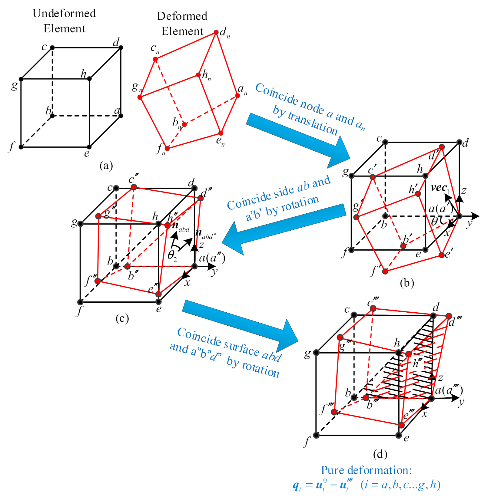
2.1. Modified VFIFE Method

Due to computing complexity and spatial structural features, the author proposed a simplified 3-D hexahedral element theory to diminish computing amount, which has been proved by comparison with FEM [32].
Solving the process of pure nodal deformation is illustrated by Figure 1, in which three steps are needed to calculate pure nodal deformation: (1) point coincidence, (2) line coincidence and (3) face coincidence. As shown in Figure 1, a black hexahedron and red hexahedron represents the element before and after deformation, respectively, with superscript 0 and n. Choose one node as the reference point as well as the origin of a local coordinate system (we deformation a as the reference point in this paper). The first step “point coincidence” (Figure 1a,b) means to make two reference points coincident by translating, which can be expressed by:
Δ u = u a n u a 0
in which u is the position vector of nodes while superscript n means the final position with deformation. The initial position 0 means initial position without deformation. Subscript a represents the point number in the element. After the first step of translation, new position of the element with superscript’ is shown in Figure 1b.
The second step “side coincidence” (Figure 1b,c) means to superpose side ab and ab′ by rotating the deformed element (the red element), while rotation angle θ 1 is between side ab and a’b and the rotation axis v e c 1 can be calculated by vector ab and ab′:
v e c 1 = a b × a b a b × a b
The third step “surface coincidence” (Figure 1c,d) means to superpose surface abd and abd′ by rotating the deformed element (the red element). Similarly, the rotation angle θ 1 is calculated by normal vectors of surface abd and abd″ ( n a b d and n a b d ), and the rotation axis v e c 2 is also obtained:
n a b d = a b   ×   a d a b   ×   a d n a b d = a b   ×   a d a b   ×   a d v e c 2 = n a b d   ×   n a b d n a b d   ×   n a b d
For any rotational axis v e c with rotational angle θ , the rotational matrix R can be written as:
R ( θ ) = [ 1 cos ( θ ) ] V 2 + sin ( θ ) V
where V = 0 v e c z v e c y v e c z 0 v e c x v e c y v e c x 0 and v e c = [ v e c x v e c y v e c z ] T . Rotational matrix R 1 or R 2 corresponding to v e c 1 or v e c 2 can be calculated by Equation (5).
Finally, the pure nodal deformation of the element is obtained (as shown in Figure 1d):
q i = u i 0 u i ( i = a , b , c , g , h )
in which u i represents deformation coordinates of node i.

2.2. Establishing of Dynamic Damping Model of Gear Dynamics

The traditional damping model defined in Equation (1), which is proportional to the magnitude of velocity with opposite directions, is not applicable for dynamics analysis because of the following: (1) damping coefficient is usually less than 0.1 and low damping coefficient could greatly reduce the rate of convergence, which multiplies the computing cost to unacceptable levels; (2) using the larger damping coefficient to accelerate the convergent process would result in distortion of the computational solution, due to over-large damping forces.
Inspired by meshing damping model used in the lumped-mass method, we decided to use the relative velocity of meshing surfaces instead of absolute velocity to describe the damping force. Section 2.2 introduces the following: (1) basic contact model and (2) how to define relative velocity and damping force. More detailed information is available in reference [32].

2.2.1. Contact Model

It is easy to find the specialty of gear meshing and surface contact: (1) contact surface is certain and simple repeating (tooth profile); (2) contact deformation is regarded as elastic deformation; (3) small contact deformation reduces the difficulty of nonlinear computational convergence as well as contact search. From these characteristics, we determine to apply master–slave algorithm and inside–outside algorithm for global search and local search, respectively.
The master–slave algorithm was firstly proposed to solve the contact behavior of contact–impact problem widely used in finite element software [33]. In this method, two contact surfaces are defined as master face and slave face, on which nodes are master nodes and slave nodes. The core idea of inside–outside local search algorithm is judging the master node located in or out of the effective region of the element using vectors, as detailed in reference [34].

2.2.2. Relative Velocity and Damping Model

As discussed in the preceding Section, damping force defined by f d = ζ m x ˙ is not suitable for high-speed rotor dynamics. Therefore, a relative velocity damping force model is proposed in this paper.
It is not difficult to find that velocity x ˙ used in static analysis is a simplified equation of a complete expression, which means x ˙ is the velocity difference between transient state and static state, or more precisely, velocity difference between transient state and steady state. Damping model can be redefined by f d = ξ Δ x ˙ in this way. ξ is damping ratio and Δ x ˙ = x ˙ t x ˙ t _ s t e a d y represents velocity difference. Since x ˙ t _ s t e a d y is a fluctuating value for dynamics, theoretical velocity x ˙ t h e o can be used to replace x ˙ t _ s t e a d y and Δ x ˙ can be written as Δ x ˙ = x ˙ t x ˙ t h e o . For node i, the relative velocity is obtained:
Δ x ˙ i = x ˙ i _ t x ˙ i _ t h e o = x ˙ i _ t ω t h e o × r i
in which r i is rotation radius of node i, ω t h e o is theoretical angular velocity at time t, for gear ω t h e o = ω g t , and for pinion ω t h e o = ω p t . Angular velocity norm ω g t and ω p t at time t can be calculated by nodes on gear body:
ω g t = k = 1 l v g k r g k l ,   ω p t = j = 1 n v p j r p j n
where l and n represent the number of body nodes (represented by k and j) on gear and pinion, v g k and v p j are velocity magnitudes, r g k and r p j are radius of rotation axis.
Therefore, we could define damping force as:
f d i = ξ m i Δ x ˙ i = ξ m i ( x ˙ i _ t ω t h e o × r i )
Then, the damping model was established.
Plug Equation (9) into Equation (1) and the control equation can be written as:
m x ¨ = P + f ξ m Δ x ˙

3. Basic Model of SBG

3.1. Basic Parameters and Machine-Tool Settings

Based on the design method of spiral bevel gears [35,36], basic parameters and machine-tool settings were designed and list in Table 1 and Table 2.

3.2. Models and Settings

According to gear engagement theory and modeling method, the mesh model of spiral bevel gear pair can be obtained meeting assembly conditions, as shown in Figure 2. Node A is on the root of web structure connecting with shaft which is a reference point in results discussion.
After installation, gear and pinion both take the right meshing position. Nodes inside gear body have been imposed restrictions (as highlighted in Figure 2): both pinion and gear release the rotational DOF of rotational axis while rotational speed and load torque are applied on pinion and gear, respectively. Material properties and working parameters are as follows: elastic modulus E = 2.06 × 10 5 MPa, Poisson’s ratio μ = 0.29, applied torque on gear T = 800 Nm, input rotational speed ωp = 20,000 rpm. The friction was ignored due to its negligible effect on dynamic behavior.

4. SBG Dynamic Analysis with Different Web Thicknesses

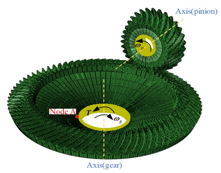
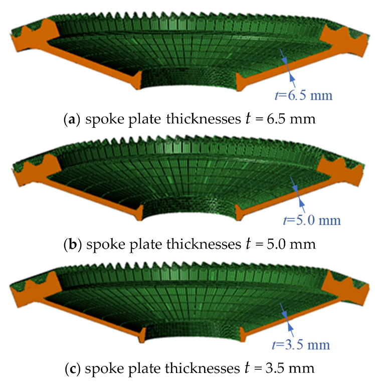
4.1. Model Establishment

Thin-web structure thicknesses would increase system flexibility, change system mass and natural frequency, in which the lightweight is rather important in aviation equipment. Therefore, influences of web thicknesses on the SBG dynamic behaviors would be analyzed. According to design parameters of an aviation SBG, the web thicknesses t would be set as 6.5 mm, 5.0 mm and 3.5 mm, respectively, as shown in Figure 3.

4.2. Results Discussion

Models with different web thicknesses were simulated by the modified VFIFE method proposed in Section 2. Contact force, contact stress and dynamic transmission error are discussed, respectively. There are four simulation groups in this section: SBG model with no web, SBG model with web thicknesses t = 6.5 mm, SBG model with web thicknesses t = 5.0 mm, and SBG model with web thicknesses t = 3.5 mm. The group of SBG model with no web is a control group to reflect the influence of web structure. To eliminate effects of web support angles, the angles are all set as 70°. All the four groups are simulated in the same parameters, including working conditions, constrained conditions, damping coefficient and other simulation settings to ensure comparability between different groups. The proposed method performs well in simulation speed, where it costs less than 8 h even for the 140-thousand-element models (with computing conditions: single-core i7-CPU with 2.6 GHz, RAM 8 GB, programming language C++). More than 40 tooth meshing processes were simulated and were extremely stable. Since the accuracy was discussed in a former study (refer to reference [31]) and needs further experiment verification, it is neglected here.

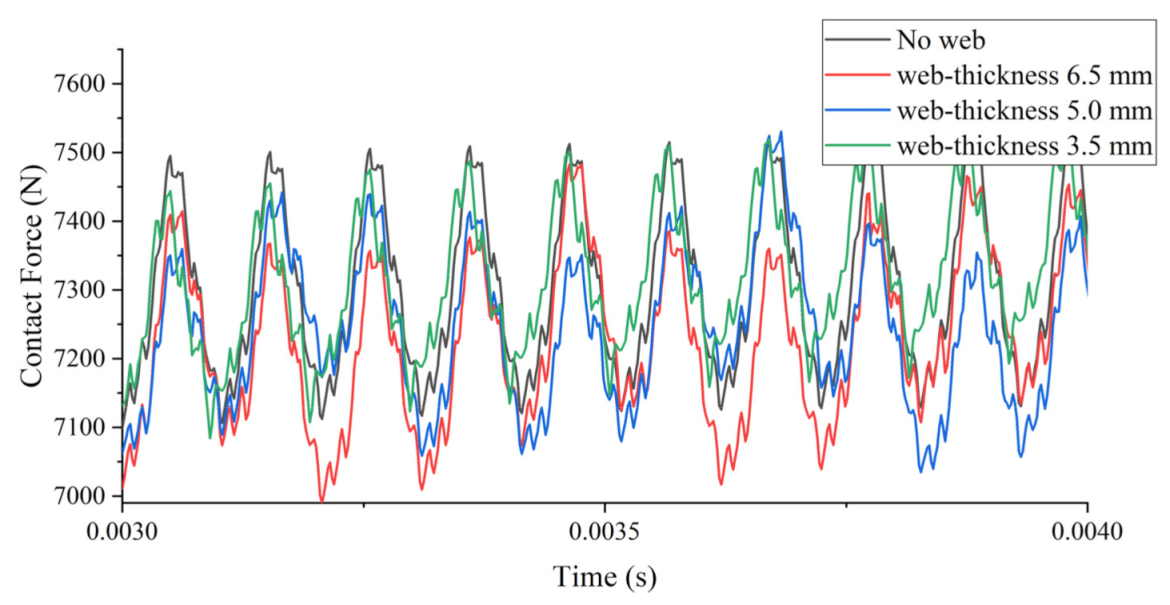
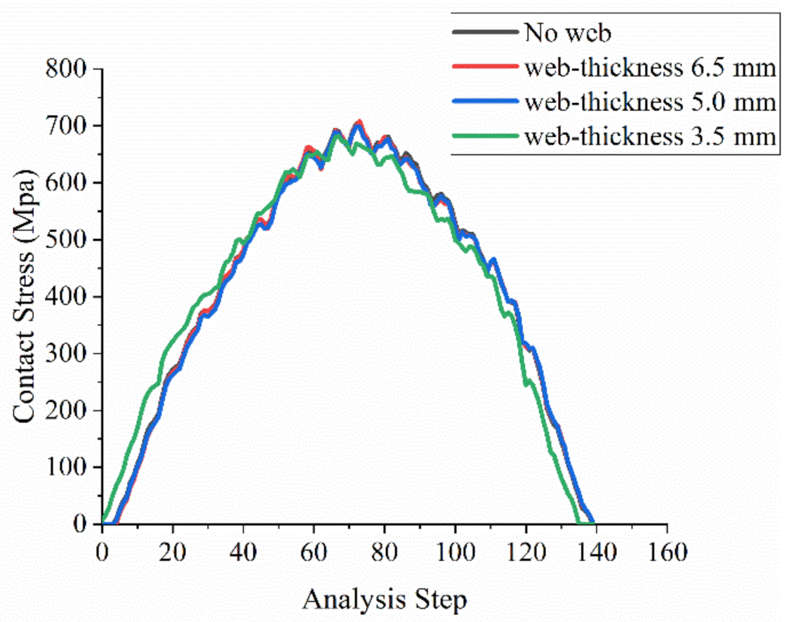
4.2.1. Contact Force and Contact Stress

The total contact force is obtained by the summation of contact force on each meshing tooth surface. Equaling to contact force of gear, the contact force of pinion is analyzed as the object. To make the change rules much clearer, the results were intercepted for several periods, as illustrated in Figure 4. It can be seen from the figure that absolute values of the contact force were affected little by web structure, while periodicity shows obvious differences. For the model with no web, the data is nearly strictly the same for each cycle. On the contrary, dynamic forces of models with web structure illustrated distinctly low-frequency signal superposition, which are caused by flexibility of the web structure. In addition, different web structure thickness models show different low-frequency changing rules and fluctuation for model with web thickness 3.5 mm seems smallest.
Based on the contact force simulation results, the contact was calculated according to the contact area. Since subtle differences of contact force values between different model, the contact stresses would show few differences. Taking one tooth surface for example, the contact stress curves are exhibited in Figure 5. Due to the same analysis process, the abscissa uses steps instead of time.
It can be concluded from Figure 4 and Figure 5 that web structure has little influence on the gear surface meshing performance. Therefore, tooth surface design can be conducted directly without considering web structure thickness.

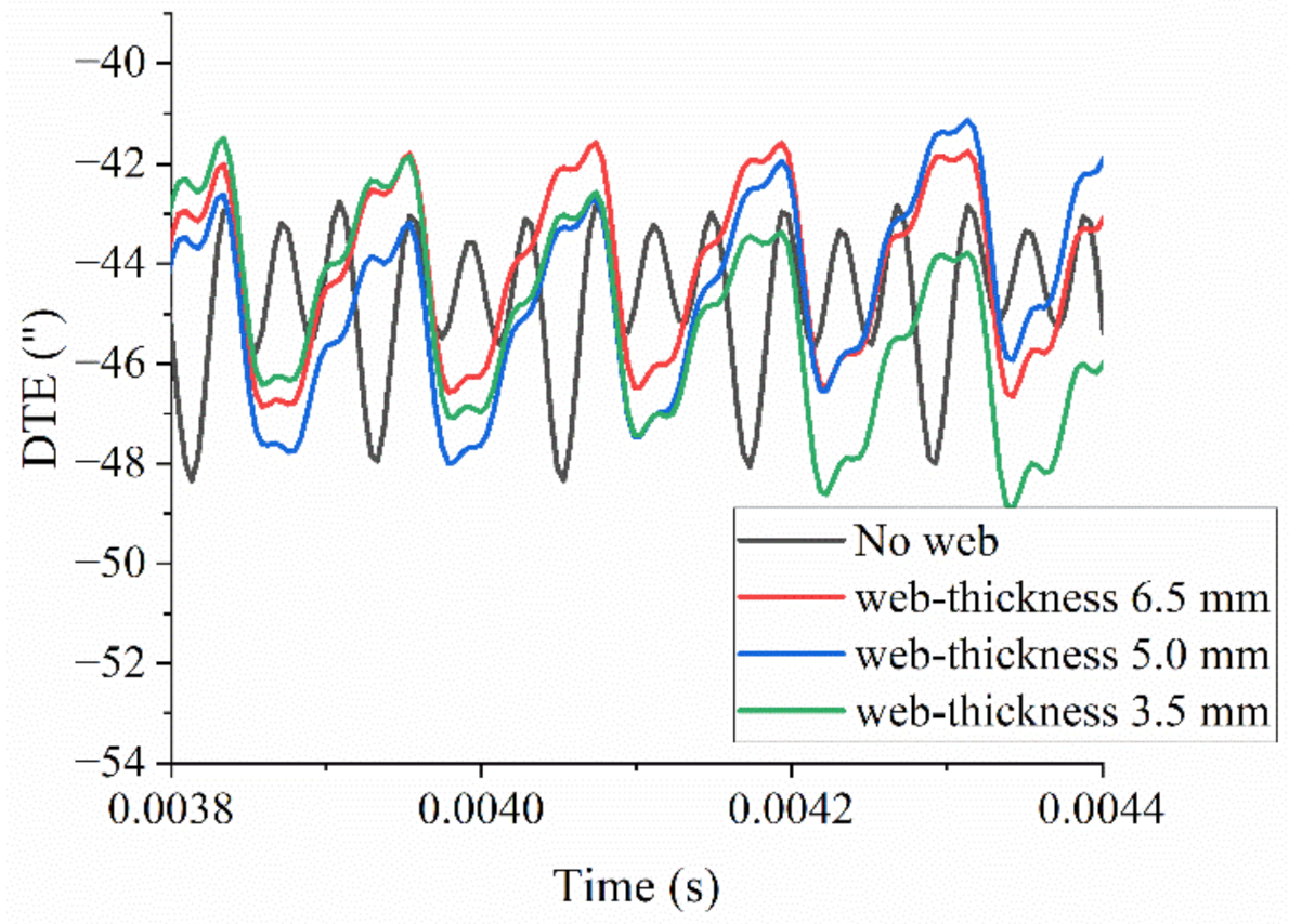
4.2.2. Dynamic Transmission Error

The effect of web structure thickness on SBG meshing performance is discussed, where the results show few differences between models. However, it does not mean the dynamic responses will show the same trend. The dynamic transmission error (DTE) is one of the most important indexes representing system vibration performance, which means the deviation between theoretical and actual rotation angle and can be written as follows:
D T E = θ g z p z g θ p
in which, θ g and θ p are the actual rotating angle of gear and pinion, z g and z p are tooth numbers of gear and pinion. Due to deformation, the actual angle will always be smaller than the theoretical angle, which means the DTE should be a negative number all the time. For this simulation, θ p is theoretical because of DOF constraints. The results are shown in Figure 6, in which the transmission error is described in arc-second.
The picture shows that results of three web-structure-models appear similar trend even though low-frequency rules are different, which perform consistent with contact force change rules. However, vibration rules of the model with no web structure are totally different: (1) the period follows a strict tooth meshing cycle without any low-frequency; (2) the vibration signal shows an obvious triple meshing frequency; (3) it is not clear about meshing in or meshing out for a meshing period. These phenomena are mainly caused by constrained nodes on gear body which are too close to the gear tooth. In addition, the model with web thickness 3.5 mm shows the smallest fluctuation in a single period, which reveals that increase in web thickness could not improve dynamic transmission error.

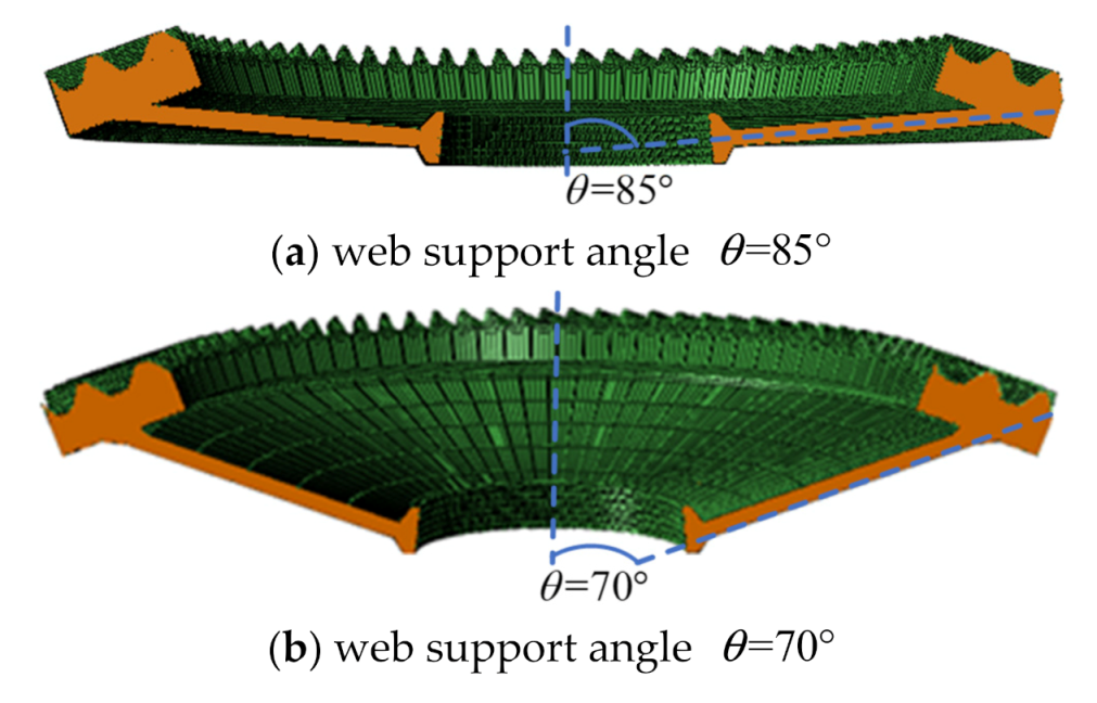
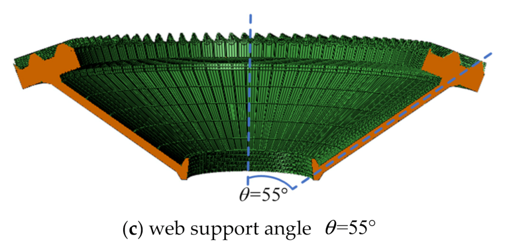
5. SBG Dynamic Analysis with Different Web Support Angles

5.1. Model Establishment

Different from web structure thickness that seems to have an obvious impact on system mass and natural frequency, web support angle would have a huge effect on vibration rules and dynamic stress. Similar to web thickness which is based on an aviation SBG parameters, the web support angle θ would be set as 55 ° , 70 ° and 85 ° respectively, as shown in Figure 7. To eliminate effects of web thickness, the web thickness is all set as 5.0 mm.

5.2. Results Discussion

Models with different web support angles were simulated by the modified VFIFE method proposed in Section 2. Contact force, contact stress and dynamic transmission error are discussed, respectively. All the three groups are simulated in the same parameters, as in Section 4.

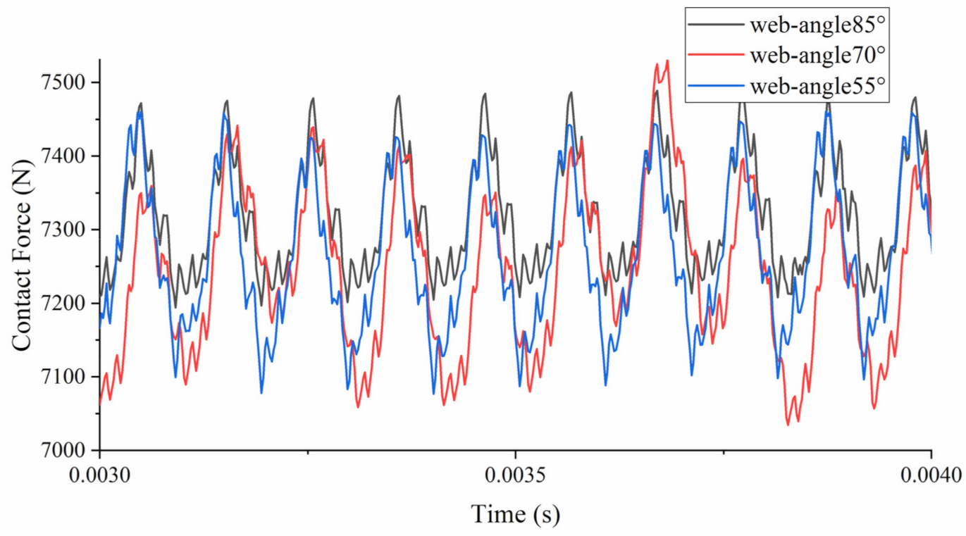
5.2.1. Contact Force and Contact Stress

Contact forces and contact stresses are calculated similar to Section 4.2.1 and the results are illustrated in Figure 8 and Figure 9.
Different from web thickness, changes of support angle have a certain effect on gear meshing properties. It can be observed clearly that contact force of the model with support angle 85° exhibits best periodicity as well as smallest contact stress (646.07 MPa), which is about 8% off compared to the other two models. The comparisons indicate that adjustment of web support angle would increase or decrease meshing quality. For this SBG example under specified working conditions, it could be concluded that a large support angle (85°) would improve meshing performance.

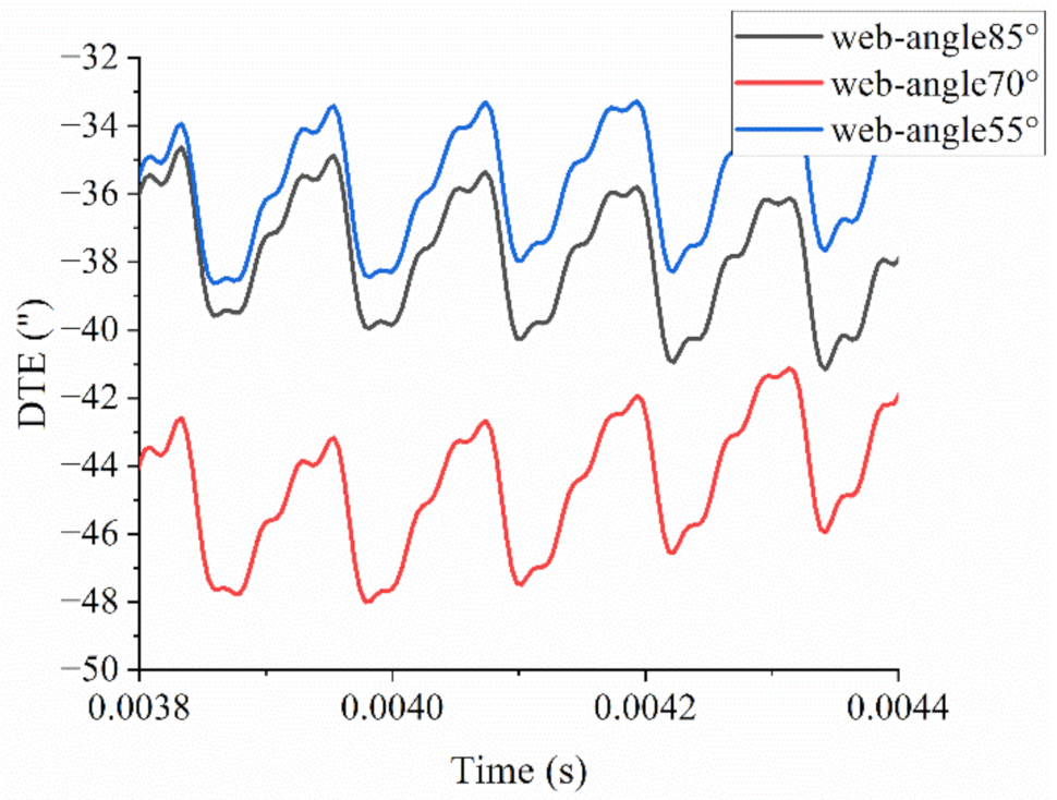
5.2.2. Dynamic Transmission Error

Dynamic transmission errors of different models are obtained based on Equation (11). These results are compared in the same coordinate system, as Figure 10 shows. It is obvious that average absolute values increase first and then decrease as the support angle becomes larger. The average values of models with web support angle 55°/70°/85° are −35.73′′/−44.24′′/−38.00′′, respectively, which illustrates that a mid-sized web support angle would increase deformation by more than 20%. In addition, changes of web support angle have little influence on DTE fluctuations. The figure also shows an obvious upward trend of DTE values for web-angle 70° and a declining trend for web-angle 85°. These trends are caused by a low-frequency period of web structure vibration. Different web design parameters would affect the mass and natural frequency of the system, which would generate a different vibration mode. The flexibility of the web structure would cause about 2 arc-second for the models with web-angle 70° and 85°, but it has much less influence on the model with web-angle 55°. When the travelling wave resonance occurs, the low-frequency period would be more remarkable, which would even result in structure failure.

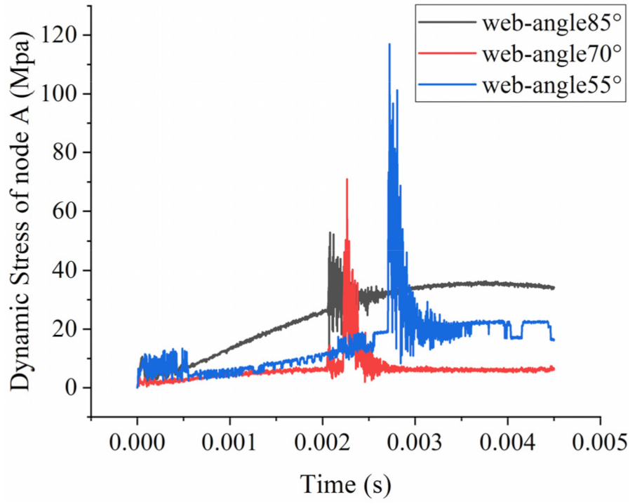
5.2.3. Dynamic Stresses

As the web structure changes, the stress distribution must be different. Unlike the impact of web thickness on web stress, wherein the wider the web thickness the stronger the structure, the influence of the support angle is not intuitive. Taking node A on the root of the web structure as an example, dynamic stresses of three different models on node A are calculated and shown in Figure 11. The peak value corresponds to the position when the distance between node A and meshing tooth pairs is nearest, which would lead to a dramatic change of stress or strain. Stresses of three different models are totally different in peak value, stable average value, lasting time, etc. For peak values, s p e a k 55 = 116.9 > s p e a k 70 = 70.9 > s p e a k 85 = 52.9 , with a maximum relative error 121% (taking the minimum as the reference). For stable average values, the relationship is s a v r 85 = 35.1 > s a v r 55 = 20.9 > s a v r 70 = 6.1 , with a maximum relative error of 475% (taking the minimum as the reference). For dynamic stress lasting time span, the relationship is s t i m e 70 0.54   ms > s t i m e 85 0.51   ms > s t i m e 55 0.48   ms , which is estimated by the fluctuation of adjacent values. Therefore, web support angle design should be based on the overall consideration of different factors.

6. Conclusions

In this paper, a series of spiral bevel gear models with web structure is established and calculated by the proposed modified VFIFE method. The influences of web structure on gear dynamic performance were discussed. From the computer simulation, the following conclusions can be made.
(1)
The proposed modified VFIFE method showed good balance in computing speed and computing accuracy. Computing time was less than 8 h for models with more than 140 thousand elements. Meshing period and rules are adequately illustrated in the results. Thus, the proposed method would be suitable for high-speed simulation.
(2)
The dynamic performance of spiral bevel gear models with different web thicknesses was simulated and compared, in which the results showed that web thicknesses had little influence on meshing performance but obviously affected dynamic transmission error.
(3)
The dynamic performance of spiral bevel gear models with different web support angles was simulated and compared, in which the results showed that support angles affected both meshing performance and dynamic characteristics more distinctly than web thicknesses.
For future work, the accuracy of the proposed method should be verified by experiment. In addition, system dynamics considering bearings and shafts could be further discussed.

Author Contributions

Conceptualization, X.H. and L.Q.; data curation, Y.Z. and Z.L.; formal analysis, X.H.; funding acquisition, X.H. and S.-K.L.; methodology, L.Q. and X.H.; resources, R.Z. and S.-K.L.; supervision, Z.L., R.Z. and S.-K.L.; visualization, Y.Z.; writing—original draft, L.Q. and X.H. All authors have read and agreed to the published version of the manuscript.

Funding

This research was funded by [the National Key Research and Development Program of China] grant number [2020YFB2010200], [National Natural Science Foundation of China] grant number [52105060], [Natural Science Foundation of Jiangsu Province] grant number [No.BK20200428], and [the Regional Leading Research Center of NRF and MOCIE] grant number [NRF-2019R1A5A8083201].

Institutional Review Board Statement

Not applicable.

Informed Consent Statement

Not applicable.

Data Availability Statement

The raw/processed data required to reproduce these findings cannot be shared at this time as the data also forms part of an ongoing study.

Conflicts of Interest

The authors declare no conflict of interest.

References

  1. Geng, Z.; Xiao, K.; Wang, J.; Li, J. Nonlinear Dynamic Analysis of a Rigid–Flexible Gear Transmission Considering Geometric Eccentricities. J. Comput. Nonlinear Dyn. 2020, 15, 084501. [Google Scholar] [CrossRef]
  2. Liu, J.; Pang, R.K.; Ding, S.Z.; Li, X.B. Vibration analysis of a planetary gear with the flexible ring and planet bearing fault. Measurement 2020, 165, 108100. [Google Scholar] [CrossRef]
  3. Hao, C.Y.; Feng, G.B.; Sun, H.G.; Li, H.P. Rigid-flexible coupling dynamics simulation of planetary gear transmission based on MFBD. J. Vibroeng. 2017, 19, 5668–5678. [Google Scholar] [CrossRef]
  4. Yavuz, S.D.; Saribay, Z.B.; Cigeroglu, E. Nonlinear dynamic analysis of a drivetrain composed of spur, helical and spiral bevel gears. Nonlinear Dyn. 2020, 100, 3145–3170. [Google Scholar] [CrossRef]
  5. Li, Z.W.; Wen, B.R.; Peng, Z.K.; Dong, X.J.; Qu, Y.G. Dynamic modeling and analysis of wind turbine drivetrain considering the effects of non-torque loads. Appl. Math. Model. 2020, 83, 146–168. [Google Scholar] [CrossRef]
  6. Liu, C.; Fang, Z.D.; Wang, F. An improved model for dynamic analysis of a double-helical gear reduction unit by hybrid user-defined elements: Experimental and numerical validation. Mech. Mach. Theory 2018, 127, 96–111. [Google Scholar] [CrossRef]
  7. Liu, C.; Fang, Z.D.; Liu, X.; Hu, S.Y. Multibody dynamic analysis of a gear transmission system in electric vehicle using hybrid user-defined elements. Proc. Inst. Mech. Eng. Part K J. Multi-Body Dyn. 2019, 233, 30–42. [Google Scholar] [CrossRef]
  8. Xu, X.Y.; Tao, Y.C.; Liao, C.R.; Dong, S.J.; Chen, R.X. Dynamic Simulation of Wind Turbine Planetary Gear Systems with Gearbox Body Flexibility. Stroj. Vestn.-J. Mech. Eng. 2016, 62, 678–684. [Google Scholar] [CrossRef]
  9. Shi, W.; Park, Y.; Park, H.; Ning, D.Z. Dynamic analysis of the wind turbine drivetrain considering shaft bending effect. J. Mech. Sci. Technol. 2018, 32, 3065–3072. [Google Scholar] [CrossRef]
  10. Cho, S.; Choi, J.; Choi, J.H.; Rhim, S. Numerical estimation of dynamic transmission error of gear by using quasi-flexible-body modeling method. J. Mech. Sci. Technol. 2015, 29, 2713–2719. [Google Scholar] [CrossRef]
  11. Chandrasekaran, M.; Nandakumar, P. Study of Mesh Stiffness of Spur Gear Tooth by Considering Pitting Defect under Dynamic Load Conditions. In 3rd International Conference on Advances in Mechanical Engineering; IOP Publishing: London, UK, 2020; Volume 912. [Google Scholar] [CrossRef]
  12. Ren, F.; Li, A.S.; Shi, G.Q.; Wu, X.L.; Wang, N. The Effects of the Planet-Gear Manufacturing Eccentric Errors on the Dynamic Properties for Herringbone Planetary Gears. Appl. Sci. 2020, 10, 1060. [Google Scholar] [CrossRef] [Green Version]
  13. Marafona, J.D.M.; Marque, P.M.T.; Martins, R.C.; Seabra, J.H.O. Towards constant mesh stiffness helical gears: The influence of integer overlap ratios. Mech. Mach. Theory 2019, 136, 141–161. [Google Scholar] [CrossRef]
  14. Hua, X.; Chen, Z.G. Effect of roller bearing elasticity on spiral bevel gear dynamics. Adv. Mech. Eng. 2020, 12, 1687814020938895. [Google Scholar] [CrossRef]
  15. Belingardi, G.; Cuffaro, V.; Cura, F. Multibody approach for the dynamic analysis of gears transmission for an electric vehicle. Proc. Inst. Mech. Eng. Part C J. Eng. Mech. Eng. Sci. 2018, 232, 57–65. [Google Scholar] [CrossRef] [Green Version]
  16. Filgueira da Silva, S.; Eckert, J.J.; Carvalho, A.C.; Mazzariol Santiciolli, F.; Silva, L.C.A.; Dedini, F.G. Multi-body Dynamics Co-simulation of Planetary Gear Train for Dynamic Meshing Force Analysis. In Multibody Mechatronic Systems. Papers from the MuSMe Conference in 2020. Mechanisms and Machine Science (MMS 94); Springer: Cham, Switzerland, 2021; pp. 159–167. [Google Scholar] [CrossRef]
  17. Yu, W.N.; Mechefske, C.K.; Timusk, M. The dynamic coupling behaviour of a cylindrical geared rotor system subjected to gear eccentricities. Mech. Mach. Theory 2017, 107, 105–122. [Google Scholar] [CrossRef]
  18. Xiuquan, S.; Tie, W.; Ruiliang, Z.; Fengshou, G.; Ball, A.D. Modelling of Spur Gear Dynamic Behaviours with Tooth Surface Wear. In Advances in Asset Management and Condition Monitoring. COMADEM 2019. Smart Innovation, Systems and Technologies (SIST 166); Springer: Cham, Switzerland, 2020; pp. 1437–1449. [Google Scholar] [CrossRef]
  19. Kim, J.G.; Gang, G.A.; Cho, S.J.; Lee, G.H.; Park, Y.J. Dynamic Stiffness Effect of Mechanical Components on Gear Mesh Misalignment. Appl. Sci. 2018, 8, 844. [Google Scholar] [CrossRef] [Green Version]
  20. Li, S.T. Effects of centrifugal load on tooth contact stresses and bending stresses of thin-rimmed spur gears with inclined webs. Mech. Mach. Theory 2013, 59, 34–47. [Google Scholar] [CrossRef]
  21. Li, Z.; Wang, H.; Zhu, R.; Ye, W. Solutions of active vibration suppression associated with web structures on face gear drives. JVE J. 2017, 14, 146–150. [Google Scholar] [CrossRef] [Green Version]
  22. Li, Z.M.Q.; Wang, H.; Zhu, R.P. Effect predictions of web active control on dynamic behaviors of face gear drives. J. Low Freq. Noise Vib. Act. Control 2019, 38, 753–764. [Google Scholar] [CrossRef]
  23. Hou, L.G.; Lei, Y.L.; Fu, Y.; Hu, J.L. Effects of lightweight gear blank on noise, vibration and harshness for electric drive system in electric vehicles. Proc. Inst. Mech. Eng. Part K J. Multi-Body Dyn. 2020, 234, 447–464. [Google Scholar] [CrossRef]
  24. Guilbert, B.; Velex, P.; Cutuli, P. Quasi-static and dynamic analyses of thin-webbed high-speed gears: Centrifugal effect influence. Proc. Inst. Mech. Eng. Part C J. Eng. Mech. Eng. Sci. 2019, 233, 7282–7291. [Google Scholar] [CrossRef]
  25. Guilbert, B.; Velex, P.; Dureisseix, D.; Cutuli, P. Modular hybrid models to simulate the static and dynamic behaviour of high-speed thin-rimmed gears. J. Sound Vib. 2019, 438, 353–380. [Google Scholar] [CrossRef]
  26. Hou, X.Y.; Zhang, Y.Z.; Zhang, H.; Zhang, J.; Li, Z.M.Q.; Zhu, R.P. A modified damping model of vector form intrinsic finite element method for high-speed spiral bevel gear dynamic characteristics analysis. J. Strain Anal. Eng. Des. 2022, 57, 144–154. [Google Scholar] [CrossRef]
  27. Duan, Y.F.; Wang, S.M.; Yau, J.D. Vector Form Intrinsic Finite Element Method for Analysis of Train-Bridge Interaction Problems Considering The Coach-Coupler Effect. Int. J. Struct. Stab. Dyn. 2019, 19, 29. [Google Scholar] [CrossRef]
  28. Li, X.M.; Guo, X.L.; Guo, H.Y. Vector form intrinsic finite element method for nonlinear analysis of three-dimensional marine risers. Ocean Eng. 2018, 161, 257–267. [Google Scholar] [CrossRef]
  29. Duan, Y.F.; Tao, J.J.; Zhang, H.M.; Wang, S.M.; Yun, C.B. Real-time hybrid simulation based on vector form intrinsic finite element and field programmable gate array. Struct. Control Health Monit. 2019, 26, 21. [Google Scholar] [CrossRef] [Green Version]
  30. Chen, J.L.; Yang, R.C.; Zhao, Y. Application of vector form intrinsic finite element on integrated simulation of wind turbine. Struct. Des. Tall Spec. Build. 2017, 26, 11. [Google Scholar] [CrossRef]
  31. Hou, X.; Fang, Z.; Zhang, X. Static contact analysis of spiral bevel gear based on modified VFIFE (vector form intrinsic finite element) method. Appl. Math. Model. 2018, 60, 192–207. [Google Scholar] [CrossRef]
  32. Hallquist, J.O.; Goudreau, G.L.; Benson, D.J. Sliding interfaces with contact-impact in large-scale Lagrangian computations. Comput. Methods Appl. Mech. Eng. 1985, 51, 107–137. [Google Scholar] [CrossRef]
  33. Sheng Ping, W.; Nakamachi, E. The inside-outside contact search algorithm for finite element analysis. Int. J. Numer. Methods Eng. 1997, 40, 3665–3685. [Google Scholar] [CrossRef]
  34. Litvin, F.L.; Fuentes, A. Gear Geometry and Applied Theory; Cambridge University Press: Cambridge, UK, 2004; p. 493. [Google Scholar]
  35. Jinzhan, S.; Zongde, F.; Xiangwei, C. Design and analysis of spiral bevel gears with seventh-order function of transmission error. Chin. J. Aeronaut. 2013, 26, 1310–1316. [Google Scholar]
  36. Litvin, F.L.; Fuentes, A.; Hayasaka, K. Design, manufacture, stress analysis, and experimental tests of low-noise high endurance spiral bevel gears. Mech. Mach. Theory 2006, 41, 83–118. [Google Scholar] [CrossRef]
Figure 1. Solution procedure of pure nodal deformation where. (a) initial element and deformed element; (b) superpose initial element and deformed element at reference node a; (c) superpose initial element and deformed element at reference side a; (d) superpose initial element and deformed element at reference face abd.
Applsci 12 03084 g001
Figure 2. Mesh model and constraint conditions.
Applsci 12 03084 g002
Figure 3. Mesh model with different spoke plate thicknesses.
Applsci 12 03084 g003
Figure 4. Contact forces of models with different web thickness.
Applsci 12 03084 g004
Figure 5. Contact stresses of models with different web thickness.
Applsci 12 03084 g005
Figure 6. Dynamic transmission error of models with different web thickness.
Applsci 12 03084 g006
Figure 7. Mesh model with different web support angles.
Applsci 12 03084 g007aApplsci 12 03084 g007b
Figure 8. Contact forces of models with different web support angles.
Applsci 12 03084 g008
Figure 9. Contact stresses of models with different web support angles.
Applsci 12 03084 g009
Figure 10. Dynamic transmission errors of models with different web support angles.
Applsci 12 03084 g010
Figure 11. Dynamic stresses of models with different web support angles.
Applsci 12 03084 g011
Table 1. Basic parameters.
ItemsPinionGear
Tooth number2779
Modulus (mm)3.153.15
Pressure angle (°)2020
Mean spiral angle (°)3030
Face width (mm)3030
Shaft angle (°)9090
Mean cone distance (mm)116.49116.49
Hand of spiralRightLeft
Pitch angle (°)18.8771.13
Root angle (°)17.972.1
Addendum (mm)3.341.32
Dedendum (mm)1.913.94
Table 2. Machine-tool settings.
ItemsPinionGear
ConcaveConvex-
Profile angle (°)202020
Point radius (mm)94.0196.1894.26
Cutter diameter (mm)152.4190.5
Cradle angle (°)−50.44−48.8150.16
Radial distance (mm)104.53108.77107.42
Blank offset (mm)1.41−0.620
Machine center to back (mm)−1.16−0.130
Sliding base (mm)0.410.10−0.50
Machine root angle (°)17.9069.44
Publisher’s Note: MDPI stays neutral with regard to jurisdictional claims in published maps and institutional affiliations.

