Article

System-Level Assessment of Low Complexity Hybrid Precoding Designs for Massive MIMO Downlink Transmissions in Beyond 5G Networks

1
Department of Information Science and Technology, ISCTE-Instituto Universitário de Lisboa, 1649-026 Lisbon, Portugal
2
Instituto de Telecomunicações, 1049-001 Lisbon, Portugal
*
Author to whom correspondence should be addressed.
Appl. Sci. 2022, 12(6), 2812; https://doi.org/10.3390/app12062812
Submission received: 3 February 2022 / Revised: 28 February 2022 / Accepted: 7 March 2022 / Published: 9 March 2022
(This article belongs to the Special Issue Transmission Techniques for 5G and Beyond, Volume Ⅱ)

Abstract

:
The fast growth experienced by the telecommunications field during the last few decades has been motivating the academy and the industry to invest in the design, testing and deployment of new evolutions of wireless communication systems. Terahertz (THz) communication represents one of the possible technologies to explore in order to achieve the desired achievable rates above 100 Gbps and the extremely low latency required in many envisioned applications. Despite the potentialities, it requires proper system design, since working in the THz band brings a set of challenges, such as the reflection and scattering losses through the transmission path, the high dependency with distance and the severe hardware constraints. One key approach for overcoming some of these challenges relies on the use of massive/ultramassive antenna arrays combined with hybrid precoders based on fully connected phase-shifter architectures or partially connected architectures, such as arrays of subarrays (AoSAs) or dynamic AoSAs (DAoSAs). Through this strategy, it is possible to obtain very high-performance gains while drastically simplifying the practical implementation and reducing the overall power consumption of the system when compared to a fully digital approach. Although these types of solutions have been previously proposed to address some of the limitations of mmWave/THz communications, a lack between link-level and system-level analysis is commonly verified. In this paper, we present a thorough system-level assessment of a cloud radio access network (C-RAN) for beyond 5G (B5G) systems where the access points (APs) operate in the mmWave/THz bands, supporting multi-user MIMO (MU-MIMO) transmission with massive/ultra-massive antenna arrays combined with low-complexity hybrid precoding architectures. Results showed that the C-RAN deployments in two indoor office scenarios for the THz were capable of achieving good throughput and coverage performances, with only a small compromise in terms of gains when adopting reduced complexity hybrid precoders. Furthermore, we observed that the indoor-mixed office scenario can provide higher throughput and coverage performances independently of the cluster size when compared to the indoor-open office scenario.

1. Introduction

In recent years we have been witnessing the increasing deployment of the fifth generation of wireless communications (5G). This generation represents a significant mark in the way we communicate, enabling new applications that would be otherwise infeasible with the technology of previous generations. Therefore, several new technologies were incorporated into 5G which were crucial to achieving all the requirements that are needed for the operation of these systems. However, the telecommunications field is experiencing fast growth over the last few decades, which has been motivating the academy and the industry to invest in the design, testing and deployment of the next generation of wireless communications (6G). Within this context, terahertz (THz) communications have been attracting more and more attention, being referred to by the research community as one of the most promising research fields on the topic, not only for the availability of spectrum but also because of the achievable rates that can be offered to the users [1,2].
THz systems are becoming feasible due to the recent advances in the field of THz devices, and they are expected to ease the spectrum limitations of today’s systems [3]. However, there are several issues that can affect the system performance, such as the reflection and scattering losses through the transmission path, the high dependency between range and frequency of channels in the THz band and also the need for controllable time-delay phase shifters. Such limitations require not only the proper system design but also the definition of a set of strategies to enable communications [4,5]. According to the literature, some of the challenges for beyond 5G networks (B5G) are the fabrication of plasmonic nano array antennas, channel estimation, precoding, signal detection, beamforming, and beamsteering [6]. To overcome the distance limitation in THz communications, one can take advantage of the very large antenna arrays that can be implemented at these bands while minimizing interference between multiple users. However, when working with massive/ultra-massive arrays of antennas, a fully digital precoder is often not feasible and hybrid designs must be used instead. Regarding the hybrid precoder, it is necessary to adopt the most adequate architecture in order to maintain the intended trade-off between performance and complexity. Fully-connected (FC) structures based on phase shifters, arrays of subarrays (AoSAs) and dynamic arrays of subarrays (DAoSAs) represent some of the most referred to architectures in the literature [7,8,9,10,11]. From the energy efficiency (EE) and power consumption perspective, which are particularly relevant, and the mmWave/THz bands, the use of partially connected (PC) structures, such as AoSAs and DAoSAs, can be more efficient than fully connected structures. In particular, DAoSAs represent a much more appealing solution since they can offer a good compromise (in terms of performance) between fully connected structures, which have a higher implementation complexity (especially with a massive number of antennas), and AoSAs, which are lighter but can suffer significant degradation in performance. Concerning this topic, one can find in the literature a wide range of schemes for multiple-input multiple-output (MIMO) systems considering both uplink and downlink scenarios [7,8,9,10,11], but there is a significant imbalance between the number of approaches aimed at those scenarios for hybrid precoding at higher frequencies. The authors of [12] proposed two algorithms for low-complexity hybrid precoding and beamforming for multi-user (MU) mmWave systems. Even though they assume only one stream per user, i.e., the number of data streams (Ns) is equal to the number of users (Nu), it is shown that the algorithms achieve interesting results when compared to the fully-digital solution. The concept of precoding based on adaptive RF-chain-to-antenna was only introduced in [13] for single user (SU) scenarios but showed promising results. In [14], a nonlinear hybrid transceiver design relying on Tomlinson–Harashima precoding was proposed. Their approach only considers FC architectures but can achieve a performance close to the fully-digital transceiver. Most of the hybrid solutions for mmWave systems aim to achieve near-optimal performance using FC structures, resorting to phase shifters or switches. However, the difficulty of handling the hardware constraint imposed by the analog phase shifters or by switches in the THz band is an issue that limits the expected performance in terms of SE. In [15], the authors proposed a low complexity design based on the alternating direction method of multipliers (ADMM) that can approximate the performance of a hybrid precoder to the fully-digital performance. It is targeted to the millimeter wave (mmWave)/THz bands and can incorporate different architectures at the analog component of the precoder, making it suitable for supporting ultra-massive MIMO (UM-MIMO) in severely hardware-constrained systems that are typical at these bands. There are some recent experimental demonstrations of hybrid precoding schemes for MIMO mmWave communications, as mentioned in [16,17]. However, these implementations still have limitations in the size of the adopted arrays and the number of RF chains. Regarding the applications of these schemes in the THz band, the technology is still in the early stages and there are still no UM-MIMO implementations with hybrid precoding/beamforming. Nevertheless, there are already some simpler MIMO implementations in THz, such as the ones mentioned in [18,19].
When transitioning from a link-level perspective to a system-level analysis, we must deal with several other issues, such as distance limitation, signal-to-noise ratio (SNR) degradation, weak coverage areas and blind zones, which are particularly relevant when working in the high-frequency spectrum [11,20,21]. This is the main reason why network and resource allocation planning are crucial when deploying these systems for cellular communications, independently of the scenario under study [11,22]. There are few system-level evaluations of mmWave schemes in the literature, such as the ones mentioned in [23,24], but beyond all the proposals in the field of system-level analysis very few examples have been extended to the 5G New Radio (5G NR) standard of the 3rd Generation Partnership Project (3GPP) and for the THz level (e.g., 100 GHz) as we cover in this paper. This standard suggests the use of deterministic cluster delay lines (CDLs) for link-level simulations, which requires the definition of average angles of departure (AODs) and arrival (AOAs) and also a tapped delay line (TDL). For system-level simulations, a full three-dimensional (3D) modeling of a radio channel is recommended since this type of analysis requires a statistical approach [25,26].
Motivated by the work above, in this paper, we study a cloud radio access network (C-RAN) for 5G and beyond systems which is based on the adoption of low complexity hybrid precoding designs for massive and ultra-massive multi-user MIMO (MU-MIMO) schemes operating in the mmWave/THz bands. As far as the authors are aware there are no previous studies similar to the one presented in this paper focusing on the system-level evaluation of robust hybrid algorithms with different architectures (FC, AoSA, DaoSA, etc.) at the THz band. The C-RAN studied in this paper assumes that each access point (AP) uses the precoder to remove the multi-user interference (MUI) generated at the receivers, breaking the MU communication into equivalent small SU links, which enables a lower complexity at the receiver side. We consider a virtualized C-RAN, where the network determines which APs are to be associated with each terminal. The cell moves with and always surrounds the terminal in order to provide a cell-center experience throughout the entire network. Each terminal designated as user equipment (UE) is served by its preferred set of APs. The actual serving set for a UE may contain one or multiple APs and the terminal’s data are partially or fully available at some cluster with potential serving APs. The AP controller (Central Processor) will accommodate each UE with its preferred cluster and transmission mode at every communication instance while considering load and channel state information (CSI) knowledge associated with the cluster of APs [27].
The main contributions of this paper can be summarized as follows:
  • Thorough system-level assessment of a virtualized C-RAN with two clusters sizes, namely, size 1 and 3, where the APs operate in the mmWave/THz bands with massive/ultra-massive antenna arrays combined with low-complexity hybrid precoding architectures. The system-level simulations were performed based on link-level results between the APs and multiple terminals, where it is considered that the ADMM algorithm from [15] is applied for hybrid precoding design at the transmitter side.
  • System-level evaluation of the proposed C-RAN in two 5G NR three-dimension (3D) scenarios, namely, the indoor-mixed office (InD-MO) and indoor-open office (InD-OO).
  • System-level evaluation demonstrates that low-complexity hybrid precoding-based C-RAN deployments in an indoor scenario can enable the practical implementation of those schemes, which rely on massive/ultra-massive antenna arrays to combat distance limitation and minimize the MUI. While these hybrid designs sacrifice some performance, significant throughput performance and coverage improvements can still be achieved over typical cellular networks.
  • System-level assessment of the proposed based C-RAN with the fifth numerology of 5G NR in the 3D indoor-mixed office scenario with different parameters, such as the number of transmitting antennas per user and the number of subcarriers, with the results benchmarked against two alternative MU-MIMO schemes.
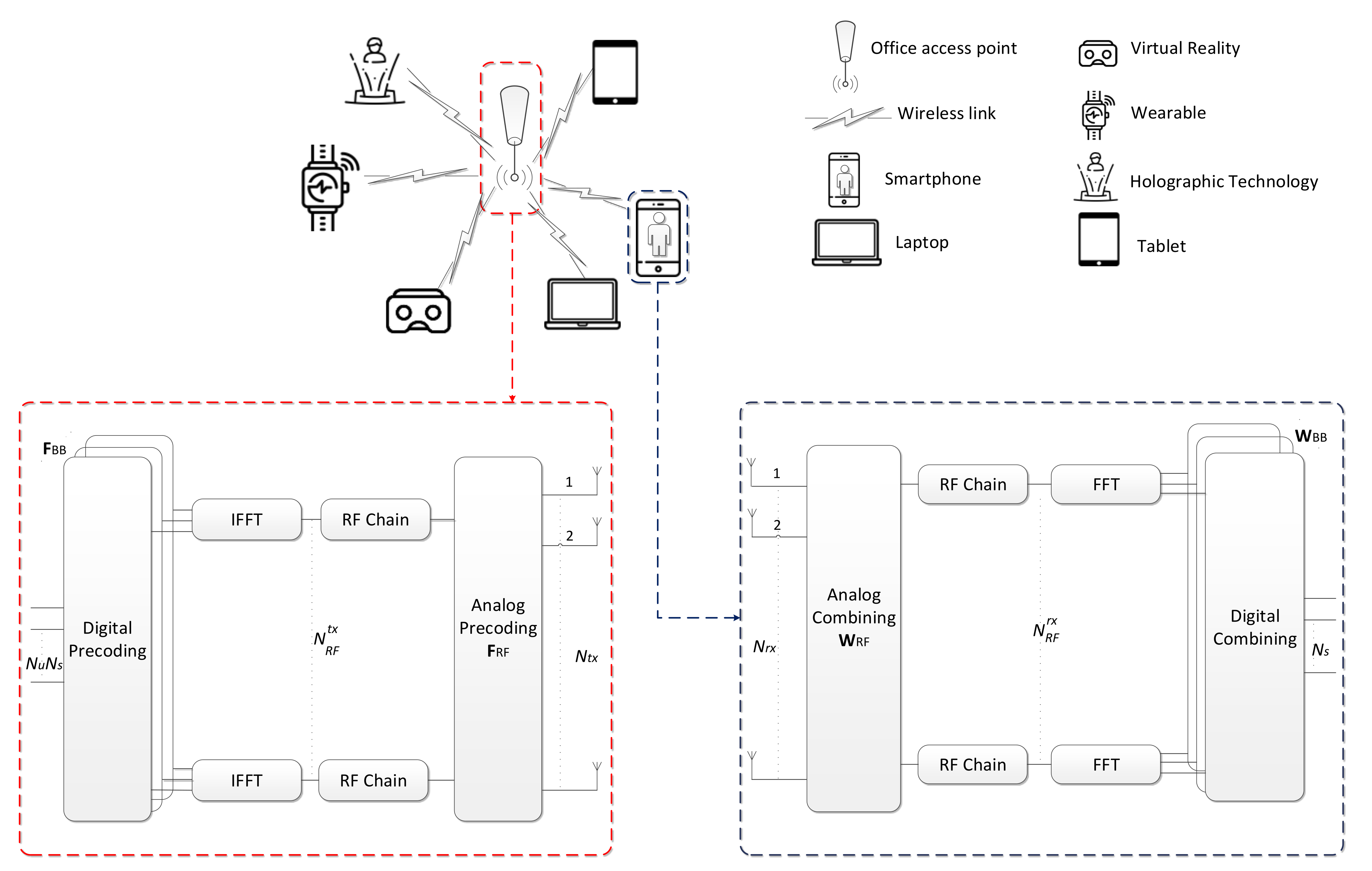
In Table 1, we present a list of acronyms adopted along with the text in order to improve the readability of the paper. The paper is organized as follows: Section 2 presents the model for the low-complexity hybrid precoding system and the system-level scenario that is considered in the evaluation. Section 3 presents and discusses the system-level simulations results, whereas the conclusions are outlined in Section 4.
Notation: Matrices and vectors are denoted by uppercase and lowercase boldface letters, respectively. (.)T and (.)H denote the transpose and the conjugate transpose of a matrix/vector, p is the p -norm of a vector, 0 is its cardinality, is the floor function and I n is the n × n identity matrix.

2. System Model

2.1. Transmitter and Receiver Model

Let us consider a mmWave/THz hybrid MU-MIMO system, where an AP is equipped with N t x antennas that transmit to N u users simultaneously over F carriers. Each user is equipped with N t x antennas that transmit to N u users simultaneously. Each user is equipped with N r x antennas over F carriers, such as the one described in Figure 1. N s data streams are transmitted to each user and to each subcarrier, which can be represented as s k = s k , 1 T s k , N u T T , with s k , u N s × 1 . Since a fully digital design would require a dedicated RF chain per antenna element, both the digital and analog processing blocks of the precoder and combiner are separated. By following this approach, it is possible to use reduced digital blocks with only a few radio frequency (RF) chains, which can be complemented by the analog blocks that are based on networks of phase-shifter and switches solely. It is assumed that N u N s N R F t x N t x and N s N R F r x N r x , where N R F t x and N R F r x are the number of RF chains at the AP and each user, respectively. The received signal model at user u and subcarrier k after the combiner can be written as:
Y k , u = ρ u W BB k , u H W RF u H H k , u F RF F BB k s k + W BB k , u H W RF H n k , u ,
where H k , u N r x × N t x is the frequency domain channel matrix (assumed to be perfectly known at the transmitter and receiver) between the AP and the uth receiver at subcarrier k. F RF N tx × N RF tx and W RF u N r x × N R F r x represent the analog precoder and combiner, with u = 1 , , N u , ρ u denoting the average received power and vector n k , u N r x × 1 contain independent zero-mean circularly symmetric Gaussian noise samples with covariance σ n 2 I N r x . The digital baseband precoders are denoted by F BB k N R F t x × N u N s and the combiners by W BB k , u N R F r x × N s . In order to maintain the complexity of the implementation limited, the analog component is the same for all subcarriers, which means that F RF and W RF will be the same for all subcarriers.
Considering the major issues related to spectral efficiency (SE), energy consumption and hardware implementation for THz pointed out in the introduction, in this study, we considered the architectures depicted in Figure 2 [15,28,29,30,31]. The FC architecture is the closest to the performance of the digital architecture, but it is also the most power-consuming of the hybrid architectures. This is the main motivation for the development of partially connected architectures (AoSAs and DAoSAs) with the aim of trying to achieve similar performances to FC structures, but with lower energy consumption. The AoSAs architectures, especially the ones based on phase shifters, can be divided into two categories, namely, the ones based on single-phase shifters (SPS) and the ones based on double-phase shifters (DPS). Increasing the number of phase shifters connected to each antenna results in an improved performance but entails a higher energy consumption. On the other hand, DAoSAs represent a much more appealing solution due to the good compromise between performance and energy consumption (EC). However, the choice of the most suitable architecture depends on several aspects, which are related to the calculation of the F RF and F BB matrices. When considering an FC structure with SPS, the F RF will be dense with all elements having unit amplitude. Nevertheless, if we consider the case of the AoSA architecture, the F RF elements also have unit amplitude, but the matrix structure is
F RF = blkdiag { f R F , 1 , , f R F , N R F } = f R F , 1 0 0 f R F , N R F ,
with f R F , i = f 1 R F , i , , f N t x N R F R F , i U N t x / N R F , 1 for i = 1 , N R F . In the case of the DAoSA architecture, the matrix is similar to the case of the AoSA but can have a number of non-null columns in each row of up to the maximum number of subarrays that can be connected to an RF chain (Lmax). If we consider DPS-based architectures, the amplitude of the elements becomes less than or equal to 2.
Several schemes were proposed in the literature to calculate the matrices F RF and F BB , such as [12,29]. The approach suggested in [15] can calculate F RF and F BB by the approximation of the digital F for any of these four structures. The overall optimization problem can be then expressed as:
min F RF , F BB k k = 1 F F opt k F RF F BB k F 2
subject   to   F RF C N t x × N R F t x
F RF F BB k F 2 = N u N s .
In this formulation, the matrix F opt k denotes the fully-digital precoder and Equation (5) enforces the transmitter’s total power constraint and C N t x × N R F is the set of feasible analog precoding matrices, which is defined according to the adopted RF architecture. In order to enforce F RF F BB k , u to lie in the null space of H ¯ k , u ( N u 1 ) N r x × N t x , we write the following restriction to the overall optimization problem expressed in (3) to (5):
F RF F BB k , u N H ¯ k , u ,
with k = 1 , , F and u = 1 , , N u . H ¯ k , u is a matrix corresponding to H k with the N r x lines of user u removed, which we denote as N H ¯ k , u . Other RF constraints can be directly integrated into the objective function of the optimization problem in order to cope with the different RF architectures.

2.2. Channel Model

Even though mmWave and THz bands share a few similarities, the THz channel presents several unique features that differentiate it from the mmWave channel. In the THz band, the very high scattering and diffraction losses tend to result in a much sparser channel in the angular domain with fewer multipath components (typically less than 10) [20]. Because of the referred phenomenon, the gap between the line of sight (LOS) and non-line of sight (NLOS) components tends to be very large, which often makes LOS-dominant with NLOS-assisted [28]. An additional aspect relies on the much larger bandwidth of THz signals which can suffer performance degradation due to the so-called beam split effect, where the transmission paths squint into different spatial directions depending on the subcarrier frequency [29]. In light of this, in this paper, we consider a clustered wideband geometric channel, which is commonly adopted both in mmWave [12] and THz literature [5,6,30,31]. However, it should be noted that the hybrid precoding/combining approach proposed in this paper is independent of a specific MIMO channel. In this case, the frequency domain channel matrices can be characterized as:
H k , u = γ α u L O S a r ϕ u r , L O S , θ u r , L O S a t ϕ u t , L O S , θ u t , L O S H + + i = 1 N c l l = 1 N r a y α i , l , u a r ϕ i , l , u r , θ i , l , u r a t ϕ i , l , u t , θ i , l , u t H e j 2 π τ i , u f k ,
where N c l denotes the number of scattering clusters with each cluster i, with a time delay of τ i , u and N r a y is the number of propagation paths per cluster. α u L O S and α i , l , u are the complex gains of the LOS component and of the lth ray from cluster i. Index u is the user ( u = 1 , , N u ), f k = f c + B F k 1 F 1 2 ( k = 1 , , F ) is the kth subcarrier frequency, B is the bandwidth, fc is the central frequency and γ is a normalizing factor Ε [ H k , u F 2 ] = N t x N r x . Vectors a t ϕ i , l , u t , θ i , l , u t and a r ϕ i , l , u r , θ i , l , u r represent the transmit and receive antenna array responses at the azimuth and elevation angles of ϕ i , l , u t , θ i , l , u t and ϕ i , l , u r , θ i , l , u r , respectively. Vectors a t ϕ u t , L O S , θ u t , L O S and a r ϕ u r , L O S , θ u r , L O S have similar meanings but refer to the LOS path angles ϕ u t , L O S , θ u t , L O S and ϕ u r , L O S , θ u r , L O S . By carefully selecting the parameters of the channel model it is possible to make it depict a mmWave or a THz channel. As represented in (7), this channel model includes both LOS and NLOS components. In the case of the NLOS components, we consider complex Gaussian distributed paths gains, as in [32]. Radio propagation measurements have shown that this type of cluster-based channel model can yield good agreements with real channel behavior at mmWave and subTHz frequencies [33].

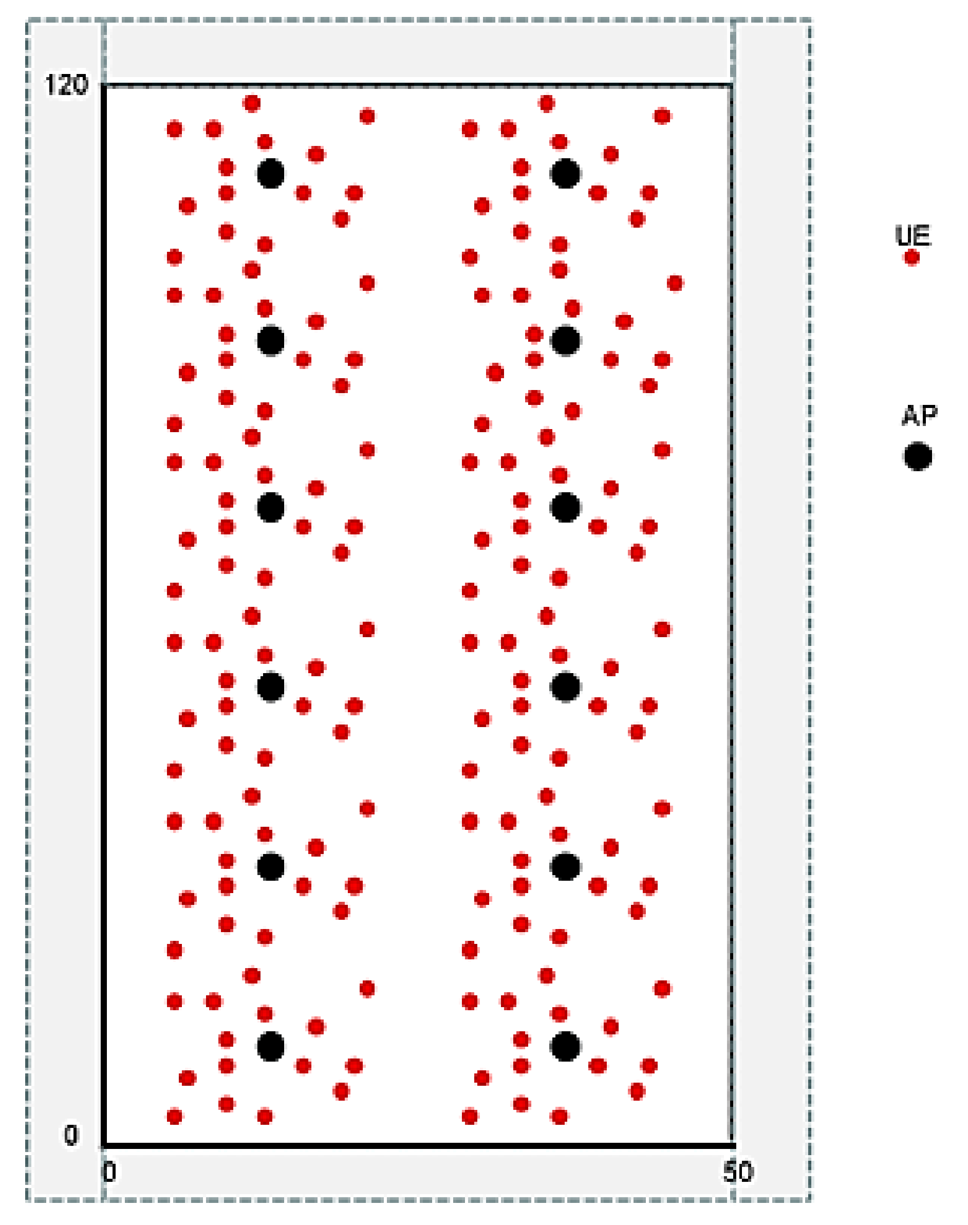
2.3. System-Level Scenario

The indoor hotspot deployment scenario focuses on small cells and high user density in buildings. This scenario, described in Table 2, represents InDs with a total area of 120 m × 50 m. There are 12 small tri-sectored cells that are deployed with an inter-site distance (ISD) of 20 m. In this case, the AP antenna height is 3 m. The coverage radius of the APs is R = 6.7 m. The carrier frequency option is 100 GHz (THz waves). The bandwidth chosen is Bt = 400 MHz corresponding to numerology five of 5G NR. Up to 16 carriers can be aggregated up to 6.4 GHz of bandwidth. It is important to note that in case of the number of users and wireless devices increasing relative to the numbers considered here, the expected behavior of the overall system will remain the same as long as carrier aggregation is used, and they will not cause inter-interference as long as they operate in different bands. A total of 15 users per AP are distributed uniformly and all users are indoors with 3 km per hour velocity as can be seen in Figure 3. A full buffer model is assumed. Our 3D simulation channel model considers the 5G NR indoor office wireless propagation environment in terms of physical aspects of mmWave and THz waves.
For this particular scenario in any considered operating frequency, the number of clusters, the number of subarrays (scatterers) per cluster and the positions of the clusters are determined by the detailed steps and procedures of [25].
According to the 5G 3GPP 3D channel models, the number of clusters and scatterers are determined using the Poisson and uniform distributions with specific parameters. Since we extend the operating frequency range up to 100 GHz, specific multi-antenna solutions and techniques need to be employed depending on the utilized spectrum. For higher frequency bands, the transmission is characterized by a considerable signal attenuation that limits the network coverage. To overcome this limitation, one of the key features is the adoption of a very large number of multi-antenna elements with a given aperture to increase the transmission/reception capability of MU-MIMO and beamforming. Since managing transmissions in higher frequency bands are complicated, beam management is necessary to establish the correspondence between the directions of the transmitter and the receiver-side beams by identifying the most suitable beam pair for both downlink and uplink.

3. Numerical Results

In this section, we present the numerical assessment of both the link- and system-level of a massive/ultra-massive MU-MIMO downlink scheme operating in the mmWave/THz band integrated into a 5G NR system, where the APs are based on the low complexity ADMM-based hybrid precoding designs. Link-level results are presented in terms of bit error rate (BER) and measure the performance of the signal across the entire communication chain, from transmitter to receivers. Both the link- and system-level diagrams can be found in references [15,27].

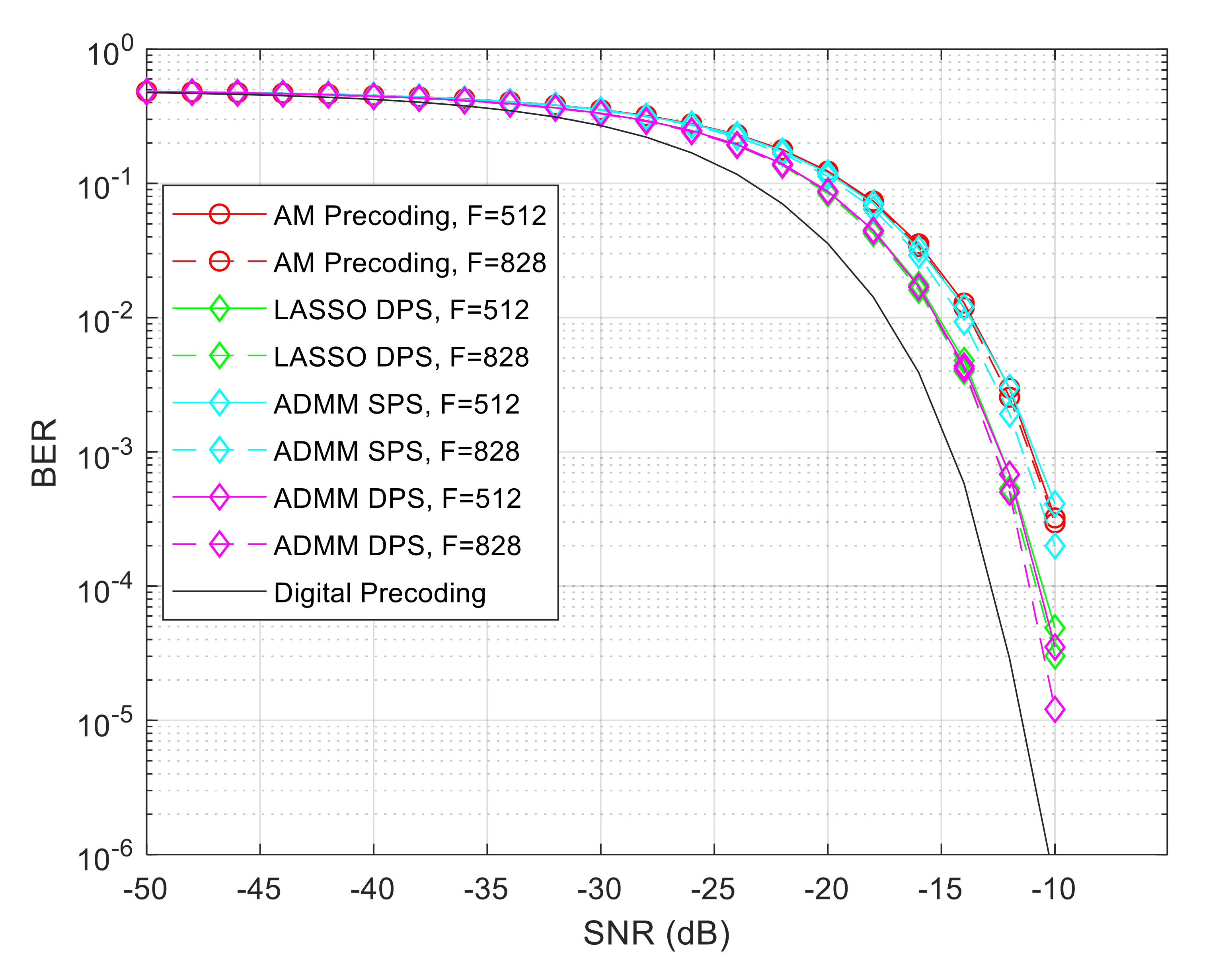
3.1. Link-Level Simulations

Considering that both the transmitter and receivers are equipped with uniform planar arrays (UPAs) with N t x × N t x antenna elements at the transmitter and N r x × N r x at the receiver, the respective array response vectors are given by
a t / r ϕ i , l , u t / r , θ i , l , u t / r = 1 N t x / r x × 1 , , e j 2 π λ d p sin ϕ i , l , u t / r sin θ i , l , u t / r + q cos θ i , l , u t / r , , e j 2 π λ d N t x / r x 1 sin ϕ i , l , u t / r sin θ i , l , u t / r + N t x / r x 1 cos θ i , l , u t / r T ,
where λ is the signal wavelength, d is the inter-element spacing (a d = λ / 2 is assumed) and p , q = 0 , , N t x / r x 1 are the antenna indices. We consider a sparse channel with limited scattering where N ray = 1 and N c l = 9 . The angles of departure and arrival were selected according to a Gaussian distribution whose means are uniformly distributed in 0 , 2 π and whose angular spreads are 10 degrees. The results are presented for an NLOS and LOS channel. This last case considers a ratio of E α u L O S 2 / i = 1 N c l l = 1 N r a y E α i , l , u 2 = 10 , which means we are admitting very weak NLOS paths when compared to LOS.
In a first approach, we compared several solutions available in the literature concerning the hybrid precoding, such as AM [12], LASSO [34] and ADMM [15] based precoding. In Figure 4, we assumed a scenario with Ntx = 100, Nrx = 4, N R F t x = 12 , Nu = 4 and Ns = 2, in which we change the number of subcarriers. To ensure a fair comparison, all schemes have a SE close to 2 bits per channel use (bpcu) per user. In this study, we considered that the hybrid precoding algorithms (LASSO and ADMM) can be applied to an architecture based on SPS or DPS, as proposed by [35].
It can be observed that the ADMM based on a DPS scheme outperforms both versions of AM and LASSO (SPS/DPS), and the gains tend to be slightly greater when the symbols are distributed over a larger number of subcarriers (F). However, the larger the number of subcarriers the greater will be the number of the required RF chains to maintain a good performance. In general, the ADMM precoding algorithm is the one that can achieve the best results at the cost of some additional computational complexity and it is also the most flexible since it can cope with different architectures, as explained in [15]. In the next subsection of the paper, we will compare these three methods based on system-level simulations.
In order to understand how many RF chains are necessary to maintain good performance as the number of subcarriers increases, we simulated the ADMM algorithm for a scenario with Ntx = 256, Nrx = 4, Nu = 4 and Ns = 2 and we changed the number of subcarriers, as can be seen in Figure 5. By maintaining the same number of RF chains as the number of subcarriers increases, some performance degradation results can be seen when we compare the curves of F = 256 and F = 512. In fact, in the case of F = 828, 10 RF chains were insufficient to provide acceptable performance and therefore 14 RF chains were employed.
After studying the performance of the ADMM precoder considering the variation of the number of subcarriers, F, and RF chains, it is important to understand the main differences in terms of performance when considering architectures based on SPS, DPS, as well as the impact of quantized phase shifters (QPS). The results are shown in Figure 6. It can be seen that a better performance can be achieved when considering a design based on a DPS over SPS. It is important to remember, however, that the architecture based on DPS provides better performance but requires the use of twice the number of phase shifters in the implementation.
In this same figure, we include QPS curves, which correspond to the SPS architecture with quantized phase shifters. It can be observed that, as expected, there is a performance loss when comparing the QPS curves against the ideal SPS, but this degradation is greatly reduced when using phase shifters with only 4 bits of quantization. Beyond, the choice of the parameters of the scenario, the BER performance can be improved by increasing the number of iterations of precoding algorithms.

3.2. System-Level Simulations

Bit and block error rate (BER/BLER) results obtained from link-level simulations are used as input for the system-level evaluation. As presented in the system model section, we consider an indoor office virtualized C-RAN, where the network determines which APs are to be associated with each UE. The total number of sites with APs is 12, which are equally spaced. Each site with APs consists of three transmission and reception points (TRPs), each one equipped with UPAs with Ntx antennas, while UEs also have one UPA with Nrx antennas. The number of antennas Ntx of each array is 100 or 256 antennas whereas the separation between antennas of the array is a half wavelength. The signal-to-noise ratio (SNR) in dB considered in the system-level simulations is obtained from SNR   = E s / N 0 + 10   l o g R s / B dB, where R s is the total transmitted symbol rate per antenna and user, B is the total bandwidth, and E s / N 0 is the ratio of symbol energy to noise spectral density in dB. Values E s / N 0 are obtained from the link-level BLER results. The BLER can be expressed using the BER, according to the following expression
BLER   =   1     ( 1     BER ) L
where L is the length of the block in bits. L can be calculated as L = 2 × F , since the selected modulation is quadrature phase shift keying (QPSK) and each subcarrier transports a symbol with 2 bits. By maintaining the reference BLER ( BLER r e f ) equal to 0.1 as the F increases, we must decrease the respective reference BER ( BER r e f ) .
We considered the fifth numerology of 5G NR with spacing between the subcarriers of 480 KHz. The transmission time interval (TTI) of this numerology is 31.25 µs and the total bandwidth is Bt = 400 MHz. Up to 16 carriers can be aggregated if more bandwidth and higher binary rates, according to the 5G NR specifications, are to be achieved. We used the 3D InD-MO channel model specified by 3GPP [25] which has a LOS probability ( P L O S ) equal to 1 for a distance lower than 1.2 m between the AP and terminals. The probability of NLOS components is P N L O S = 1 P L O S and depends on the distance between the AP and the terminals. Previously, we started our study by comparing several solutions available in the literature concerning hybrid precoding algorithms in terms of BER versus SNR.
Based on those results, we decided to analyze the performance of a system, where the APs operate in the mmWave/THz bands with massive/ultra-massive antenna arrays combined with those different hybrid precoding architectures. For this evaluation, first, we start by considering that the cluster size is equal to one. When the RAN cluster size is one (1C), we have the traditional cellular network where each AP generates inter-site interference. When the RAN cluster size is three, the network is partitioned into three adjacent site sets and each user is served at the same time by three TRPs generating much less inner interference. It is important to note that the throughput presented in the following figures concerns the average throughput value of the various UEs moving randomly throughout the 200 s of simulation. Initially, the terminals are placed uniformly distributed inside each sector served by an UPA antenna. The movement of the terminals is “Random waypoint around AP”. At every 0.5 ms of simulation, the SNR at all terminals is calculated. Those blocks which are received with SNR > SNRtarget are considered in the throughput calculation. The blocks that are received with SNR < SNRtarget are not counted in the throughput due to the throughput definition itself. SNRtarget is the SNR value for BLER r e f = 0.1. In practical terms, each block received with SNR < SNRtarget would be retransmitted until it is correctly received. However, we do not consider this situation in the simulations.
Figure 7 is based on the link-level simulation of Figure 4 presented in the previous subsection. In general, it is observed that the greater the number of subcarriers, the greater will be the throughput. As expected, the digital precoder is the one that presents the best performance in terms of throughput as the number of subcarriers and users increases. However, it is possible to approach its performance by considering the use of hybrid algorithms and their different architectures. The ADMM based on an SPS scheme is the one that presents the worst performance for a lower number of subcarriers, but when this parameter is increased it obtains a similar performance to the AM precoding algorithm. The LASSO precoding algorithm with DPS and F = 512 can obtain a slightly higher performance when compared to the ADMM DPS with F = 512. However, by increasing the number of subcarriers we observe that both algorithms obtain very similar performances. The blue curves represent the theoretical curves of average throughput value expected to be obtained based on the formula Throughput = R b max ( 1 - BLER r e f ) , where BLER r e f = 0.1 and R b max is the maximum binary transmission rate considered for the two cases F = 512 and F = 828. Contrary to what can be seen for F = 512, a loss of performance of the algorithms for F = 828 when compared to the curve of average throughput value expected for the case of F = 828, is observed. Moreover, we observe that with a fixed number of RF chains, the throughput of hybrid schemes tends to be closer to digital with F = 512 than with F = 828. When considering the digital precoding for F = 828 and 3C, a maximum SE of 1.9 bps/Hz/user can be obtained. Note that, this fact is also verified in the later graphs.
Following the study on the required number of RF chains to accommodate an increasing number of subcarriers discussed in Figure 5, it is necessary to understand how the system behaves when considering different RAN cluster sizes. In Figure 8, we can conclude that increasing the number of RF chains for higher values of F allows us to reach greater levels of throughput. Furthermore, when the cluster size increases to three (3C), as the number of users increases, the difference becomes more notorious due to the lesser inner interference caused by the network partitioning. When we have Nu = 180, the achieved throughput increases from 105.7 Gbps to 133.3 Gbps if the cluster size triples. It must be noted that for smaller blocks, such as F = 16 up to 128, the system performance is independent of cluster size. When F presents higher values, we observed that the performance difference of 1C and 3C increases with the block size.
At this point, we already know that the throughput increases as the number of subcarriers increases and the ADMM precoding algorithm constitutes an interesting alternative since it can present a good performance and can cope with different architectures, facilitating their implementation. However, it is worth understanding how the system behaves when the AP antennas are combined with different architectures based on phase shifters, as can be seen in Figure 9. Independently of the adopted architecture, it is observed that the throughput increases as the number of subcarriers increases. However, the adoption of a DPS architecture can provide a higher throughput when compared to an architecture based on SPS. This difference is even more notorious when we increase the cluster size from 1 to 3. Considering an F = 828 and 1C the version of the algorithm based on SPS can reach a throughput of 85.79 Gbps whereas the one based on DPS can reach a throughput of 99.99 Gbps. When we have 3C, both versions of the algorithm can obtain a significant improvement over the values obtained for 1C. The first one can reach a throughput of around 127.3 Gbps and the latter one reaches 132 Gbps. In fact, the version based on a DPS architecture with 3C is the one that can closely approach the digital precoding curve.
After previously analyzing two different solutions based on phase shifters, we now evaluate the performance of the system in terms of throughput and coverage with more realistic phase shifters, i.e., phase shifters with quantization. Figure 10 is based on the link-level simulation of Figure 6 presented in the previous subsection. From this figure, we observe that, as expected, by increasing the number of quantization (QPS curves) it is possible to approach the performance of the ideal unquantized version of the algorithm (SPS curve). Furthermore, it can also be seen that by increasing the cluster size, the throughput can almost double when the number of subcarriers is large. Moreover, we observe that by increasing the cluster size from 1C to 3C that the hybrid precoders curves get closer to the digital precoder curve. A lower throughput loss, due to the quantization effect, is also observed.
Following the conclusions about the previous figure concerning the impact of quantized phases shifter in the hybrid architectures, we decided to study the system performance using the same hybrid architecture in the InD-MO and the InD-OO scenarios. The throughput per user results of Figure 11 and the average coverage results of Figure 12, were simulated considering a precoder based on QPS with Nb = 3 and 4 bits. It can be observed in Figure 11 for the InD-MO scenario, that by increasing the cluster size the throughput will improve and if we consider the effect of using more quantization bits the difference becomes more notorious. When the cluster size increases from one to three, we can observe at 100 mW that the throughput doubles in both cases of quantization. If we consider the InD-OO scenario, the obtained gains present a similar behavior as the power increases but the throughput we can reach will be significantly lower. The difference between these two scenarios lies in the relative weight of the LOS and NLOS components, as the attenuation losses associated with them are the same in both scenarios. In the InD-MO scenario, the P L O S is 1 up to 1.2 m and decreases to 0.368 at 6.5 m.
In the InD-OO scenario, the P L O S is 1 up until 5.0 m and decreases to 0.538 at 49.0 m. Knowing that the P N L O S is equal to 1 P L O S , we realize that in the InD-MO scenario the weight of the NLOS component will be greater than that of the LOS component. Since the attenuation losses of NLOS are much higher than those of the LOS component, the received power of the Aps decreases rapidly with distance. Therefore, in the case of the InD-OO scenario, the weight of the LOS component is greater than the one of the NLOS component, so the transmitted power of the Aps decreases very slowly with distance generating a strong inter-site interference, which affects the maximum throughput and coverage that can be reached. Moreover, the channel can influence the results since with a stronger LOS component the multipath (NLOS component) becomes weaker, which worsens the spatial multiplexing and the spatial diversity effects. Figure 12 exhibits similar behavior when compared to the previous figure, since the greater the cluster size and the number of quantization bits, the greater the achieved coverage will be. With 3 and 4 bits of quantization at 100 mW and when the cluster size increases from one to three, we obtain a significant improvement which almost doubles the initial coverage. If we consider the InD-OO scenario, the obtained gains in terms of coverage present a similar behavior as the power increases but we can no longer obtain more than 73% of coverage (Nb = 4 bits and 3C).
In order to understand the influence of the variation of the transmitted power (Pt) of the Aps on the system-level simulation results, we considered two InD scenarios with the proposed precoder based on a DPS architecture with Ntx = 256, Nrx = 4, N R F t x = 14 , Ns = 2 and F = 828. In Table 3, we present the results of average throughput per user for both InD-OO and InD-MO scenarios when we vary the transmitted power (Pt) of each AP. We considered that P t 10 , 100 , 1000 mW. As expected, based on Figure 11 and Figure 12, the performance of scenario MO is higher than OO due to less inter-cell interference. For the same reason cluster 3C presents higher performance than cluster 1C. We can check that independently of the scenario and cluster size there is an optimum value of Pt, which is 100 mW. The highest values of throughput occur for 100 mW. This value of Pt was considered in all system-level simulations of this paper. It corresponds to the best trade-off between transmitted power and inter-cell interference. For cluster size one (1C) and InD-OO, the performance with 10 mW tends to be higher than 1000 mW due to the high inter-interference of this cluster. However, for cluster size (3C) the opposite occurs because of the lower inter-interference of this cluster.
To reduce the large performance loss due to the adoption of a simple AoSA architecture, we can allow the dynamic connection of more subarrays to each RF chain by adopting a DaoSA structure and studying the impact of the use of SPS and DPS architectures from a system-level perspective. The goal of these structures is to try to reach a compromise between fully connected structures, which are more complex to implement (especially with a massive number of antennas), and AoSAs (Lmax = 1), which are lighter but typically suffer a large performance loss.
It is possible to conclude, through Figure 13 and Figure 14, that the performance of the system can be improved as the Lmax increases. The use of DPS instead of using SPS architectures can provide higher throughputs but the difference between the gains tend to reduce when the cluster size increases. When we have 1C the gains of the DPS over the SPS can surpass 50% and with 3C we obtain gains around 20%. In general, by combining the increase in Lmax with the adoption of DPS and the cluster size, it is possible to improve the results, but the gains become less pronounced for Lmax > 1. Performance close to the digital precoding can be achieved when considering the use of a DPS scheme for Lmax = 4 and a cluster size of three. When compared to the cluster size 1C, with 3C it is observed that the throughput loss is lesser when adopting the hybrid schemes instead of the digital one.

4. Conclusions

In this paper, we described a cloud radio access network aimed at operating at the mmWave/THz bands beyond 5G systems where the access points support multi-user MU-MIMO transmission using massive/ultra-massive antenna arrays. In order to make the implementation of this scheme feasible, low-complexity hybrid precoding based on several analog architectures, namely fully connected, an array of subarrays and a dynamic array of subarrays combined with single- or double-phase shifters, was considered. Numerical evaluation of both the link- and system-level for the proposed cloud radio access network downlink scheme integrated into a beyond 5G system showed that it is possible to obtain a performance close to the digital precoding when considering scenarios with a larger number of subcarriers and users. The use of partially connected architectures (array of subarrays and dynamic array of subarrays) when compared with fully connected structures tends to achieve good performances in terms of the trade-off between spectral efficiency and energy consumption.
Assessment of the cloud radio access network deployments in two indoor office scenarios at the THz band showed the capability of achieving significant improvements in terms of throughput performance and coverage over typical cellular networks. The indoor-mixed office scenario provides higher throughput and coverage performances in comparison to the indoor-open office scenario independently of the cluster size, due to less inter-site interference. The variation of the transmitted power of the access points can impact the system results since in order to obtain a better performance an optimal value of transmitted power of around 100 mW must be considered. Furthermore, it was observed that the use of a larger cluster size, namely using 3C instead of 1C, tends to result in a lower throughput penalty when replacing a fully digital implementation with a lower complexity hybrid scheme (fully connected or dynamic array of subarrays).

Author Contributions

Conceptualization, J.P.P., A.C. and N.S.; methodology, J.P.P., A.C. and N.S.; software, J.P.P., A.C., V.V. and N.S.; validation, J.P.P., A.C., V.V., M.R., P.S. and N.S.; formal analysis, J.P.P., A.C., V.V., M.R., P.S. and N.S.; investigation J.P.P., A.C., V.V., M.R., P.S. and N.S.; resources, A.C., M.R., P.S. and N.S.; data curation, J.P.P. and A.C.; writing—original draft preparation J.P.P., A.C., V.V., M.R., P.S. and N.S.; writing—review and editing, J.P.P., A.C., V.V., M.R., P.S. and N.S.; visualization, J.P.P. and A.C.; supervision, A.C., M.R. and N.S.; project administration, A.C. and N.S.; funding acquisition, A.C. and N.S. All authors have read and agreed to the published version of the manuscript.

Funding

This work was supported by the FCT—Fundação para a Ciência e Tecnologia under the grant 2020.05621.BD. The authors also acknowledge the funding provided by FCT/MCTES through national funds and applicable co-funded EU funds under the project UIDB/50008/2020.

Institutional Review Board Statement

Not applicable.

Informed Consent Statement

Not applicable.

Data Availability Statement

The data presented in this study are available on request from the corresponding author. The data are not publicly available due to privacy.

Conflicts of Interest

The authors declare no conflict of interest.

References

  1. Dang, S.; Amin, O.; Shihada, B.; Alouini, M.S. What should 6G be? Nat. Electron. 2020, 3, 20–29. [Google Scholar] [CrossRef] [Green Version]
  2. Saad, W.; Bennis, M.; Chen, M. A Vision of 6G Wireless Systems: Applications, Trends, Technologies, and Open Research Problems. IEEE Netw. 2020, 34, 134–142. [Google Scholar] [CrossRef] [Green Version]
  3. Akyildiz, I.F.; Kak, A.; Nie, S. 6G and Beyond: The Future of Wireless Communications Systems. IEEE Access 2020, 8, 133995–134030. [Google Scholar] [CrossRef]
  4. Sarieddeen, H.; Alouini, M.-S.; Al-Naffouri, T.Y. An Overview of Signal Processing Techniques for Terahertz Communications. Proc. IEEE 2021, 109, 1628–1665. [Google Scholar] [CrossRef]
  5. Lin, C.; Li, G.Y.L. Terahertz Communications: An Array-of-Subarrays Solution. IEEE Commun. Mag. 2016, 54, 124–131. [Google Scholar] [CrossRef]
  6. Faisal, A.; Sarieddeen, H.; Dahrouj, H.; Al-Naffouri, T.; Alouini, M. Ultramassive MIMO Systems at Terahertz Bands: Prospects and Challenges. IEEE Veh. Technol. Mag. 2020, 15, 33–42. [Google Scholar] [CrossRef]
  7. Castaneda, E.; Silva, A.; Gameiro, A.; Kountouris, M. An Overview on Resource Allocation Techniques for Multi-User MIMO Systems. IEEE Commun. Surv. Tutor. 2017, 19, 239–284. [Google Scholar] [CrossRef] [Green Version]
  8. Zu, K.; de Lamare, R.; Haardt, M. Generalized Design of Low-Complexity Block Diagonalization Type Precoding Algorithms for Multiuser MIMO Systems. IEEE Trans. Commun. 2013, 61, 4232–4242. [Google Scholar] [CrossRef] [Green Version]
  9. Lopes, P.; Gerald, J. Leakage-based precoding algorithms for multiple streams per terminal MU-MIMO systems. Digit. Signal Process. 2018, 75, 38–44. [Google Scholar] [CrossRef]
  10. Guerreiro, J.; Dinis, R.; Montezuma, P.; Marques da Silva, M. On the Achievable Performance of Nonlinear MIMO Systems. IEEE Commun. Lett. 2019, 23, 1725–1729. [Google Scholar] [CrossRef]
  11. Chataut, R.; Akl, R. Massive MIMO Systems for 5G and beyond Networks—Overview, Recent Trends, Challenges, and Future Research Direction. Sensors 2020, 20, 2753. [Google Scholar] [CrossRef] [PubMed]
  12. Yuan, H.; An, J.; Yang, N.; Yang, K.; Duong, T.Q. Low Complexity Hybrid Precoding for Multiuser Millimeter Wave Systems Over Frequency Selective Channels. IEEE Trans. Veh. Technol. 2018, 68, 983–987. [Google Scholar] [CrossRef]
  13. Liu, F.; Kan, X.; Bai, X.; Du, R.; Liu, H.; Zhang, Y. Hybrid precoding based on adaptive RF-chain-to-antenna connection for millimeter wave MIMO systems. Phys. Commun. 2020, 39, 100997. [Google Scholar] [CrossRef]
  14. Xu, K.; Cai, Y.; Zhao, M.; Niu, Y.; Hanzo, L. MIMO-Aided Nonlinear Hybrid Transceiver Design for Multiuser Mmwave Systems Relying on Tomlinson-Harashima Precoding. IEEE Trans. Veh. Technol. 2021, 70, 6943–6957. [Google Scholar] [CrossRef]
  15. Pavia, J.; Velez, V.; Ferreira, R.; Souto, N.; Ribeiro, M.; Silva, J.; Dinis, R. Low Complexity Hybrid Precoding Designs for Multiuser mmWave/THz Ultra Massive MIMO Systems. Sensors 2021, 21, 6054. [Google Scholar] [CrossRef]
  16. Payami, S.; Khalily, M.; Araghi, A.; Loh, T.; Cheadle, D.; Nikitopoulos, K.; Tafazolli, R. Developing the First mmWave Fully-Connected Hybrid Beamformer With a Large Antenna Array. IEEE Access 2020, 8, 141282–141291. [Google Scholar] [CrossRef]
  17. Loh, T.; Cheadle, D.; Payami, S.; Khalily, M.; Nikitopoulos, K.; Tafazolli, R. Experimental Evaluation of a Millimeter-wave Fully-Connected Hybrid Beamformer with a Large Antenna Array. In Proceedings of the 2021 15th European Conference on Antennas and Propagation (EuCAP), Dusseldorf, Germany, 22–26 March 2021. [Google Scholar]
  18. Li, X.; Yu, J.; Wang, K.; Kong, M.; Zhou, W.; Zhu, Z.; Wang, C.; Zhao, M.; Chang, G. 120 Gb/s Wireless Terahertz-Wave Signal Delivery by 375 GHz-500 GHz Multi-Carrier in a 2 × 2 MIMO System. J. Lightwave Technol. 2019, 37, 606–611. [Google Scholar] [CrossRef]
  19. Jia, S.; Zhang, L.; Wang, S.; Li, W.; Qiao, M.; Lu, Z.; Idrees, N.; Pang, X.; Hu, H.; Zhang, X.; et al. 2 × 300 Gbit/s Line Rate PS-64QAM-OFDM THz Photonic-Wireless Transmission. J. Lightwave Technol. 2020, 38, 4715–4721. [Google Scholar] [CrossRef]
  20. Busari, S.; Huq, K.; Mumtaz, S.; Rodriguez, J. Terahertz Massive MIMO for Beyond-5G Wireless Communication. In Proceedings of the ICC 2019-2019 IEEE International Conference on Communications (ICC), Shanghai, China, 11–22 March 2019. [Google Scholar]
  21. Akyildiz, I.F.; Han, C.; Hu, Z.; Nie, S.; Jornet, J.M. TeraHertz Band Communication: An Old Problem Revisited and Research Directions for the Next Decade. arXiv 2021, arXiv:2112.13187v1. Available online: https://arxiv.org/abs/2112.13187v1 (accessed on 2 July 2021).
  22. Godinho, A.; Fernandes, D.; Soares, G.; Pina, P.; Sebastião, P.; Correia, A.; Ferreira, L.S. A Novel Way to Automatically Plan Cellular Networks Supported by Linear Programming and Cloud Computing. Appl. Sci. 2020, 10, 3072. [Google Scholar] [CrossRef]
  23. Jao, C.; Wang, C.-Y.; Yeh, T.-Y.; Tsai, C.-C.; Lo, L.-C.; Chen, J.-H.; Pao, W.-C.; Sheen, W. WiSE: A System-Level Simulator for 5G Mobile Networks. IEEE Wirel. Commun. 2018, 25, 4–7. [Google Scholar] [CrossRef]
  24. Riviello, D.G.; Di Stasio, F.; Tuninato, R. Performance Analysis of Multi-User MIMO Schemes under Realistic 3GPP 3-D Channel Model for 5G mmWave Cellular Networks. Electronics 2022, 11, 330. [Google Scholar] [CrossRef]
  25. 3rd Generation Partnership Project (3GPP). TR 38.901 v14.1.1, Study on Channel Model for Frequencies from 0.5 to 100 GHz, Release 14. 2017. Available online: www.3gpp.org/ftp/Specs/archive/38_series/38.901/38901-g10.zip (accessed on 1 November 2021).
  26. Bechta, K.; Kelner, J.; Ziółkowski, C.; Nowosielski, L. Inter-Beam Co-Channel Downlink and Uplink Interference for 5G New Radio in mm-Wave Bands. Sensors 2021, 21, 793. [Google Scholar] [CrossRef] [PubMed]
  27. Zaidi, S.; Ben Smida, O.; Affes, S.; Vilaipornsawai, U.; Zhang, L.; Zhu, P. User-Centric Base-Station Wireless Access Virtualization for Future 5G Networks. IEEE Trans. Commun. 2019, 67, 5190–5202. [Google Scholar] [CrossRef]
  28. Yuan, H.; Yang, N.; Yang, K.; Han, C.; An, J. Hybrid Beamforming for Terahertz Multi-Carrier Systems Over Frequency Selective Fading. IEEE Trans. Commun. 2020, 68, 6186–6199. [Google Scholar] [CrossRef]
  29. Yan, L.; Han, C.; Yuan, J. A Dynamic Array-of-Subarrays Architecture and Hybrid Precoding Algorithms for Terahertz Wireless Communications. IEEE J. Sel. Areas Commun. 2020, 38, 2041–2056. [Google Scholar] [CrossRef]
  30. Han, C.; Yan, L.; Yuan, J. Hybrid Beamforming for Terahertz Wireless Communications: Challenges, Architectures, and Open Problems. IEEE Wirel. Commun. 2021, 28, 198–204. [Google Scholar] [CrossRef]
  31. Ning, B.; Zhongbao, T.; Chen, Z.; Han, C.; Yuan, J.; Li, S. TeraMIMO Prospective Beamforming Technologies for Ultra-Massive MIMO in Terahertz Communications: A Tutorial. arXiv 2021, arXiv:2107.03032v2. Available online: https://arxiv.org/abs/2107.03032v2 (accessed on 2 January 2022).
  32. Basar, E.; Yildirim, I. SimRIS Channel Simulator for Reconfigurable Intelligent Surface-Empowered Communication Systems. In Proceedings of the 2020 IEEE Latin-American Conference on Communications (LATINCOM), Online, 18–20 November 2020; pp. 1–6. [Google Scholar]
  33. Ju, S.; Xing, Y.; Kanhere, O.; Rappaport, T.S. Millimeter Wave and Sub-Terahertz Spatial Statistical Channel Model for an Indoor Office Building. arXiv 2021, arXiv:2103.17127v1. [Google Scholar] [CrossRef]
  34. Yu, X.; Zhang, J.; Letaief, K. Alternating minimization for hybrid precoding in multiuser OFDM mmWave systems. In Proceedings of the 2016 50th Asilomar Conference on Signals, Systems and Computers, Pacific Grove, CA, USA, 6–9 November 2016. [Google Scholar]
  35. Yu, X.; Zhang, J.; Letaief, K.B. Doubling Phase Shifters for Efficient Hybrid Precoder Design in Millimeter-Wave Communication Systems. J. Commun. Inf. Netw. 2019, 4, 51–67. [Google Scholar]
Figure 1. Transmitter and receiver structure of a multiuser OFDM mmWave/THz MIMO system with hybrid precoding for an InD scenario.
Applsci 12 02812 g001
Figure 2. Different precoder architectures for a mmWave/THz MIMO system based on phase shifters.
Applsci 12 02812 g002
Figure 3. Indoor-office scenario layout.
Applsci 12 02812 g003
Figure 4. BER performance versus SNR achieved by different methods by changing the number of subcarriers and considering a system with Ntx = 100, Nrx = 4, N R F t x = 12 , Nu = 4 and Ns = 2 (only NLOS component).
Applsci 12 02812 g004
Figure 5. BER performance versus SNR achieved by the proposed precoder with Ntx = 256, Nrx = 4, Nu = 4, and Ns = 2, by changing the number of subcarriers and the number of RF chains (only NLOS component).
Applsci 12 02812 g005
Figure 6. BER performance versus SNR achieved by the proposed precoder with Ntx = 256, Nrx = 4, Nu = 4, N R F t x = 14 , F = 828 and Ns = 2, considering several versions of the algorithm (only NLOS component).
Applsci 12 02812 g006
Figure 7. Throughput (Gbps) vs. number of users for different methods with Ntx = 100, Nrx = 4, N R F t x = 12 and Ns = 2, by changing the number of subcarriers (only NLOS component).
Applsci 12 02812 g007
Figure 8. Throughput (Gbps) vs. number of users for different number of subcarriers, RF chains and cluster sizes, considering the proposed precoder with Ntx = 256, Nrx = 4 and Ns = 2 (only NLOS component).
Applsci 12 02812 g008
Figure 9. Throughput (Gbps) vs. number of subcarriers for different versions of the algorithm (SPS and DPS) and cluster sizes, considering the proposed precoder with Ntx = 256, Nrx = 4, N R F t x = 14 , Ns = 2 and Nu = 180 (with LOS component).
Applsci 12 02812 g009
Figure 10. Throughput (Gbps) vs. number of subcarriers for different versions of the algorithm (with and without quantization) and cluster sizes, considering the proposed precoder with Ntx = 256, Nrx = 4, N R F t x = 14 , Ns = 2 and Nu = 180 (only NLOS component).
Applsci 12 02812 g010
Figure 11. Throughput (Mbps) versus mean value of power required by each user (mW), considering the proposed precoder with Ntx = 256, Nrx = 4, N R F t x = 14 , Ns = 2, F = 828 and the quantization effect (with LOS component).
Applsci 12 02812 g011
Figure 12. Coverage (%) versus mean value of power required by each user (mW), considering the proposed precoder with Ntx = 256, Nrx = 4, N R F t x = 14 , Ns = 2, F = 828 and the quantization effect (with LOS component).
Applsci 12 02812 g012
Figure 13. Throughput (Gbps) vs. number of subcarriers for different versions of the algorithm (SPS or DPS) as a function of Lmax, considering the proposed precoder with Ntx = 256, Nrx = 4, N R F t x = 14 , Ns = 2 and Nu = 180 (with LOS component) and 1C.
Applsci 12 02812 g013
Figure 14. Throughput (Gbps) vs. number of subcarriers for different versions of the algorithm (SPS or DPS) as a function of Lmax, considering the proposed precoder with Ntx = 256, Nrx = 4, N R F t x = 14 , Ns = 2 and Nu = 180 (with LOS component) and 3C.
Applsci 12 02812 g014
Table 1. Table of acronyms.
AcronymDesignation
3DThree-dimensional
3GPPThe 3rd Generation Partnership Project
5GThe fifth generation of wireless communications
5GNR5G New radio
6GThe sixth generation of wireless communications
ADMMAlternating direction method of multipliers
AMAlternating minimization
AOAAverage angle of arrival
AODAverage angle of departure
AoSAArray of subarrays
APAccess point
B5GBeyond 5G
BERBit error rate
BLERBlock error rate
CDLCluster delay line
C-RANCloud radio access network
CSIChannel state information
DAoSADynamic array of subarrays
DPSDouble phase shifters
ECEnergy consumption
EEEnergy efficiency
FCFully-connected
InD-MOIndoor-mixed office
InD-OOIndoor-open office
LASSOLeast absolute shrinkage and selection operator
LOSLine-of-sight
MIMOMultiple Input Multiple Output
MUMulti-user
MUIMulti-user interference
MU-MIMOMulti-user MIMO
mmWaveMillimeter wave
NLOSNon-line of sight
PCPartially-connected
QPSQuantized phase shifters
UM-MIMOUltra-massive MIMO
SESpectral efficiency
SNRSignal-to-noise ratio
SPSSingle phase shifters
SUSingle-user
TDLTapped delay line
TRPTransmission and reception point
THzTerahertz
UEUser equipment
UPAUniform planar array
Table 2. Evaluation parameters for indoor-office scenario.
ParametersIndoor-Office
LayoutRoom size (WxLxH)120 m × 50 m × 3 m
ISD20 m
AP antenna height h AP 3 m (ceiling)
UE locationLOS/NLOSLOS and NLOS
Height h UE 1.5 m
UE mobility (horizontal plane only)3 km/h
Min. AP-UE distance (2D)0
UE distribution (horizontal)Uniform
Table 3. Influence of the variation of the transmitted power of the Aps on the system results.
Transmitted Power (mW)Cluster SizeAverage Throughput (Mbps)
MOOO
101C542.6388.3
103C725.6648.2
1001C551.6411.6
1003C733.4662.8
10001C526.3376.3
10003C722.3665.8
Publisher’s Note: MDPI stays neutral with regard to jurisdictional claims in published maps and institutional affiliations.

