Article

Efficient LDPC Encoder Design for IoT-Type Devices

1
Silesian University of Technology, 44-100 Gliwice, Poland
2
TKH Technology Poland Sp. z.o.o, 64-100 Leszno, Poland
*
Author to whom correspondence should be addressed.
Appl. Sci. 2022, 12(5), 2558; https://doi.org/10.3390/app12052558
Submission received: 21 January 2022 / Revised: 16 February 2022 / Accepted: 23 February 2022 / Published: 28 February 2022

Abstract

:
Low-density parity-check (LDPC) codes are known to be one of the best error-correction coding (ECC) schemes in terms of correction performance. They have been utilized in many advanced data communication standards for which the codecs are typically implemented in custom integrated circuits (ICs). In this paper, we present a research work that shows that the LDPC coding scheme can also be applied in a system characterized by highly limited computational resources. We present a microcontroller-based application of an efficient LDPC encoding algorithm with efficient usage of memory resources for the code-parity-check matrix and the storage of the results of auxiliary computations. The developed implementation is intended for an IoT-type system, in which a low-complexity network node device encodes messages transmitted to a gateway. We present how the classic Richardson–Urbanke algorithm can be decomposed for the QC-LDPC subclass into cyclic shifts and GF(2) additions, directly corresponding to the CPU instructions. The experimental results show a significant gain in terms of memory usage and decoding timing of the proposed method in comparison with encoding with the direct parity check matrix representation. We also provide experimental comparisons with other known block codes (RS and BCH) showing that the memory requirements are not greater than for standard block codes, while the encoding time is reduced, which enables the energy consumption reduction. At the same time, the error-correction performance gain of LDPC codes is greater than for the mentioned standard block codes.

1. Introduction

Internet of things (IoT) systems, which are composed of a large number of cheap, energy-efficient terminals, are some of the emerging elements of the recent landscape of information technology. The role of IoT has grown in numerous areas, such as smart homes, smart cities, Industry 4.0, agriculture, smart grids, public safety, etc. [1]. The general concept of IoT involves numerous possibilities in which a system’s hardware and software can be designed. However, the IoT nodes, which constitute the bottom level of a system, are usually devices containing a set of sensors/actuators and a low-power processor with limited processing capabilities (a microcontroller) (e.g., [2,3]). Machine-to-machine communications over the Internet in an IoT system employ a variety of last-mile communication types, with wired, wireless, or fiber-optic mediums and numerous possible stacks of protocols for the physical layer. Since nodes are usually battery powered, the energy efficiency of the protocol and its implementation is an important issue. Despite the limited resources of IoT processor devices, the implementation of efficient communication protocols is required in order to enable communication with decent power efficiency.
One of the important elements of any communication protocol stack is an error-control coding (ECC) mechanism, which has a direct influence on the effectiveness of the communication. However, the implementation of modern ECC methods with great coding gain, such as Turbo coding [4], Polar coding [5], and low-density parity-check (LDPC) coding [6,7], is known to be computationally demanding. In this paper, we present how one of the mentioned modern and power-efficient LDPC coding schemes can be implemented in a low-power microcontroller-based IoT device.

1.1. Relevant Research Works

While numerous hardware implementations of modern ECC codecs, including LDPC codecs, have already been developed, typically they are devoted to high-throughput demanding communication standards; thus, they are based on high-volume custom ICs [8,9,10], FPGAs [11,12,13,14], or GPU devices [15,16]. On the other hand, the typical physical-layer protocol stack for an IoT-type device is developed with low memory, device complexity and processing time requirements as the most important goals.
LDPC codes [6,7] are a class of linear block error-correcting codes that are known to achieve a performance near the capacity limit  [17]. Extensive research in the field of LDPC coding includes issues such as graph–theoretic representations of LDPC codes [18,19], parity-check matrix design and construction methods [20,21,22,23,24], efficient encoding [25] and decoding [26,27,28] algorithm development, ECC coding system design for different use cases [29,30], hardware implementations in ASIC and FPGA equipment [9,11,13,31,32], and the design of nonbinary codes and codecs  [22,33,34,35,36]. While LDPC codes have already been applied in a number of communication standards, such as WiMAX [37], Wi-Fi [38], and 5G [39], in this article, we show that LDPC coding can also be considered for devices with highly constrained computational resources. Despite the recent advances in digital circuit technologies, the process of codec design is still not trivial.
The research on LDPC efficient encoding implementation is quite rich already, with a number of issues that have been considered. For example, in [40], an efficient FPGA architecture for subclass of CCSDS (Consultative Committee for Space Data Systems) codes, recommended for channel coding in near-Earth and deep-space communications, is presented. The proposed architecture is based on a series of convolutional encoders, leveraging the QC structure inherent parallelism. In [41], LDPC encoding for a 5G new radio (NR) codes is considered, and a high-throughput encoder architecture is proposed. In [42], an encoding scheme is developed, involving pruning the full-base matrix of 5G NR code for a computationally efficient encoding in a high-throughput hardware architecture. The 5G NR code encoders are also considered in [16], where a GPU implementation is developed.

1.2. This Research Contributions

In the research presented in this paper, we investigate how one of the modern and power-efficient coding schemes—namely, a quasi-cyclic (QC) subclass of LDPC codes—can be applied in a device equipped with a microcontroller. The great error-correction performance of LDPC codes can then guarantee a power-efficient usage of the communications channel, regardless of the transmission medium and protocols used.
While the number of research works, including the mentioned above, involve high-throughput hardware implementations, there is a lack of LDPC codec development for the case of computationally constrained, low-power CPU devices. In this context, the research presented in this paper was initiated.
In this work, an IoT system is considered, in which the energy efficiency, due to the utilization of an advanced ECC coding, is mostly desired in an uplink direction, from the microcontroller-based IoT node, which is usually battery powered, to the IoT gateway. Therefore, the focus is on the LDPC encoding procedure, which is formulated and implemented in a low-cost CPU device. We present an efficient encoding scheme developed for a microcontroller implementation, with elementary operations corresponding directly to a CPU instructions, as well as the experimental results showing the computing time and energy reduction that can be then achieved. The contributions can be listed as follows:
  • We show how the Richardson–Urbanke encoding algorithm [43] utilized for QC-LDPC codes can be decomposed into simple, repeated operations of cyclic shifts and GF ( 2 ) additions.
  • We present a CPU implementation of this encoding with a QC-LDPC matrix representation that can be efficiently stored in the system’s RAM.
  • We provide the experimental results of the implementation in comparison with other classic block ECC schemes: the RS (Reed–Solomon) and BCH (Bose–Chaudhuri–Hocquenghem) codes. Comparisons are made in terms of memory usage, block encoding time, energy savings and error-correction performance.
For an IoT system, short-to-moderate block length codes are likely to be utilized, due to the short message lengths; therefore, we do not consider the application of state-of-the-art 5G NR codes, but instead we base the experimental part on the proprietary codes designed with a graph optimization algorithm [24].
The paper is organized as follows. In Section 2 and Section 3, we provide preliminary information about our system model of ECC in the context of IoT systems and basic definitions of LDPC coding. In Section 4, the Richardson–Urbanke encoding algorithm with a formulation specifically for QC-LDPC codes is presented. Then, in Section 5, we provide the details of the proposed microcontroller application. Finally, in Section 6, we provide the numerical results, and the paper is concluded in Section 7.

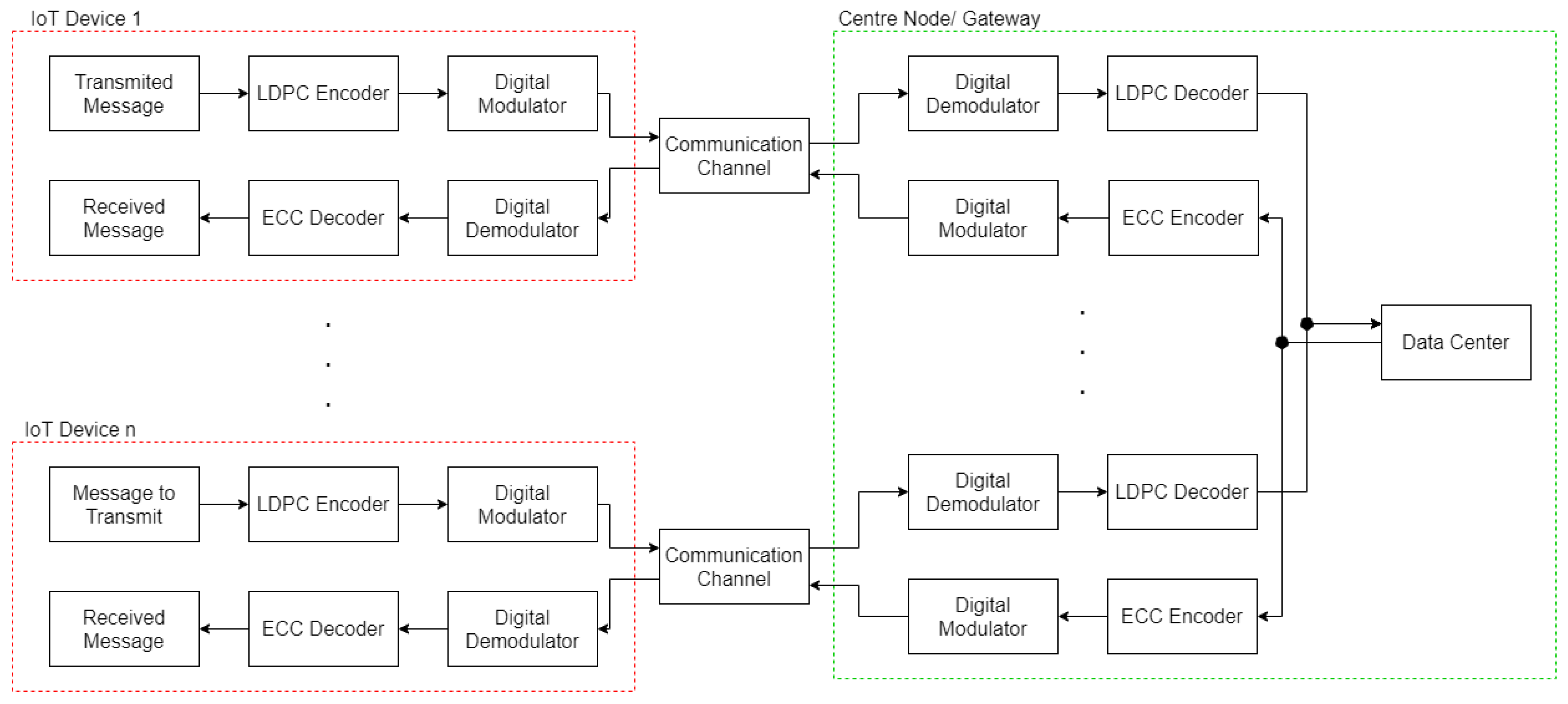
2. Error Correction for IoT End-Node Devices

We assume a communication model (Figure 1) in which a number of low-complexity IoT devices communicate with a central node—the gateway. Since we consider the gateway to possess great computational resources, an ECC scheme with a high decoding complexity can be considered for data blocks sent from devices to the gateway (the uplink direction). Therefore, LDPC coding seems to be an attractive option because of its great correction performance, which has the potential to save transmission power. However, in such a model, the LDPC encoder still needs to be implemented in an IoT node. In this article, we present the results of an investigation that aims to answer the question of how to optimize the LDPC encoder’s implementation in a typical microcontroller, as well as to find out what the memory requirements and timing parameters of such a solution are.
As shown in Figure 1, the presented solution is devoted to a microcontroller-based IoT device with any physical layer, wired or wireless, requiring computationally efficient and energy-efficient ECC. Therefore, the details of the protocol are abstracted as a digital modulation and communication channel in the system model considered. The developed coding system is utilized in an industrial implementation with a fiber-optic communication link, with highly constrained optical power. This is an example of practical application of the presented ideas.
IoT device nodes are typically based on small microcontrollers with limited resources and peripherals, such as a universal asynchronous receiver–transmitter (UART), SPI and I2C serial interfaces, etc. Some of these peripherals are configured to work with very-low-power modes; most of the time, IoT devices are in sleep mode, waiting for a wake-up, and then send a message upon the occurrence of some event. Considering ECC message encoding, the energy efficiency of such a message delivery is dependent on two factors:
  • The encoding time, which is connected with encoding complexity;
  • The coding scheme gain, which is the possible reduction in transmission power due to the application of an effective ECC scheme.
These two factors are likely contradictory because an effective ECC scheme that enables transmission power reduction usually has a high encoding—and especially decoding—complexity. Therefore, we propose the utilization of an LDPC coding scheme in the uplink direction, and we present how an LDPC encoder can be efficiently realized with a microcontroller. As presented in Figure 1, the assumed system model does not fix any specific ECC scheme for the downlink direction (from the gateway to the IoT node).

3. LDPC Codes

3.1. Preliminaries

A binary ( N , K ) LDPC code is defined by its binary parity-check matrix H of size M × N , where N is the code vector length, M = N K is the number of parity-check bits, and K < N is the length of an information vector. The code redundancy is indicated by the code rate, which is defined as R = K / N . In the systematic encoding process, M parity bits are added to the information vector u = { u 1 , u 2 , , u K } , forming the code vector (code word) c = { c 1 , c 2 , , c N } . In the mathematical formulation, the vectors are over the Galois field GF ( q ) —specifically, GF ( 2 ) for the binary codes considered in this paper.
In the decoder, the received data in a row vector c ^ of length N are recognized as a correct (error-free) vector if, and only if, they satisfy the parity-check equation H c ^ T = 0 M × 1 with GF ( 2 ) arithmetic. If the parity-check equation is not satisfied, error-correction decoding is required, which is applied by means of the iterative belief propagation algorithm [7].
To be effectively and efficiently utilized in an IoT system, the LDPC code should usually satisfy requirements regarding the code rate R = K / N , the code-word length N, decent error correction performance, and the possibility of implementing an encoder using very limited resources. Our proposed encoding scheme is versatile; that is, a broad range of N and R can be engaged, and we will present the results for a number of parity-check matrices with different N and R. Unlike the frequently considered advanced communication devices based on custom ICs and FPGAs, we consider an IoT device with highly limited resources: limited memory and only a single computation core (CPU).

3.2. QC-LDPC Codes

The quasi-cyclic subclass of low-density parity check codes (QC-LDPC) [44] is known to possess a desirable feature of organized message routing in hardware implementations of a partially parallel decoder. QC-LDPC codes are used for most LDPC coding system designs, industrial applications [11,22,37,39,44], etc. Their characteristic feature is the block-circulant structure of H . The parity-check matrix H of a QC-LDPC code consists of a grid of square P × P submatrices, with each submatrix being the following: 
-
An all-zero zero matrix;
-
An identity matrix;
-
An identity matrix with circularly shifted columns.
Additionally, the implementation of a low-complexity encoder using the classic Richardson–Urbanke method [43] requires an ALT (almost lower triangular) form, preferably a dual-diagonal structure of H  [45]. Let us denote a P × P circulant permutation matrix (CPM) as P s , which is obtained by cyclically shifting the identity matrix I P × P by s positions to the right. In this article, a class of codes with the following structure of the parity-check matrix H is considered:
H = P s 1 , 1 P s 1 , 2 P s 1 , J P s 2 , 1 P s 2 , 2 P s 2 , J P s I , 1 P s I , 2 P s I , J ,
where s i , j { 0 , 1 , , P 1 , } , where P = 0 is used to denote the all-zero matrix [45]. Codes associated with the parity-check matrix as in (1) are ( N , K ) QC-LDPC codes with code vector length N = J P , information vector length K = ( J I ) P , and rate R = ( J I ) / J .
Alternatively to the matrix representation, the LDPC codes can also be represented by the associated bipartite Tanner graph [7,46]. In the Tanner graph, variable nodes representing data bits are associated with columns of H , and check nodes representing parity checks are associated with rows of H . The nonzero elements in H are represented by the edges in the code graph. The Tanner graph defines the passage of the message through the iterative decoding algorithm [7], but it is also involved in numerous methods of code construction with optimized performance [20,47,48].

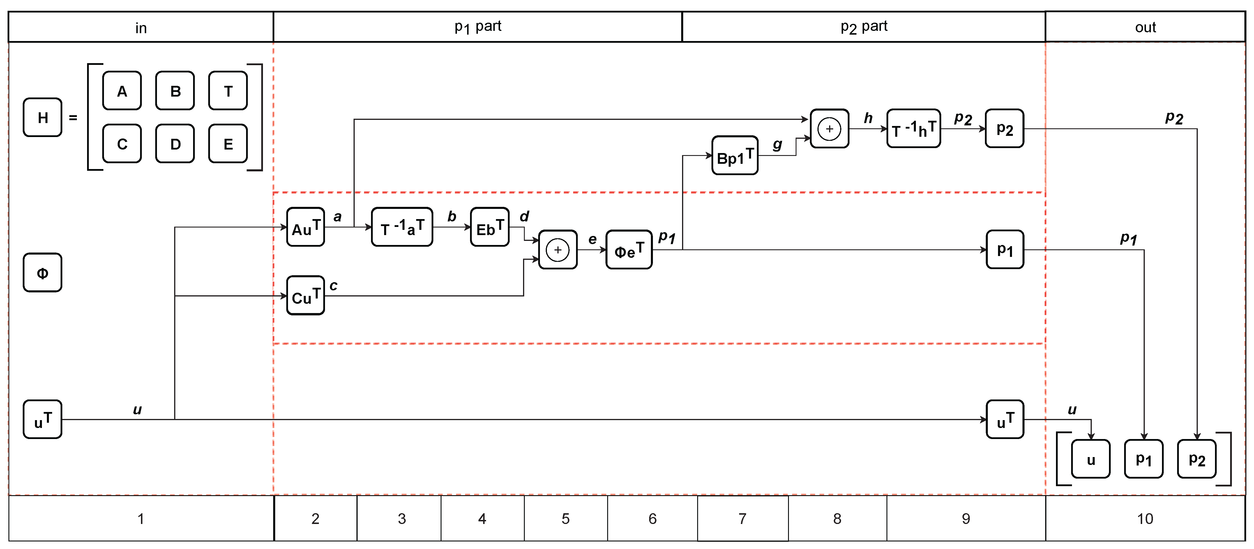
4. Richardson–Urbanke Encoding Algorithm

A basic encoding method for any linear block codes can be based on a generator matrix. However, in general, the generator matrix of an LDPC code is a dense N × K matrix, which in itself is a great amount of data for storing in limited memory, and it requires dense matrix operations. Therefore, it is desirable to employ a more efficient LDPC encoding method, as introduced by Richardson and Urbanke [43], who directly utilized the parity-check matrix H , which is sparse by definition. This method requires an H matrix in an ALT form. Let us shortly introduce the Richardson–Urbanke method in the context of QC-LDPC codes.
We assume that by making use of some of the known methods [20,24], the parity-check matrix is constructed in (or converted into) an ALT form, with P × P submatrices of the QC-LDPC structure. Let the H in ALT form be partitioned as follows:
H = A B T C D E ,
where A is of size ( I g ) P × ( J I ) P , B is ( I g ) P × g P , T is ( I g ) P × ( I g ) P , C is g P × ( J I ) P , D is g P × g P , and E is g P × ( I g ) P , where g is the gap size, that is, the size of the non-triangular part. The structure of the T matrix is essential, which should be lower triangular, that is,
T = P 0 0 0 0 P s 2 , ( J I + g + 1 ) P 0 0 0 P s 3 , ( J I + g + 1 ) P s 3 , ( J I + g + 2 ) P 0 0 P s ( I g ) , ( J I + g + 1 ) P s ( I g ) , ( J I + g + 2 ) P s ( I g ) , ( J 1 ) P 0
where P 0 is an identity matrix of size P × P . An important feature is that T 1 multiplication by any vector can be performed with linear complexity through a back-substitution operation [43].
The systematic encoding process of an information vector u = { u 1 , u 2 , , u K } is based on determining two parity sub-vectors p 1 and p 2 with lengths g P and ( I g ) P , respectively, such that the obtained code vector is c = [ u , p 1 , p 2 ] . Considering (2), the parity-check equation Hc T = 0 can be divided into two parts:
A u T + B p 1 T + T p 2 T = 0 ,
C u T + D p 1 T + E p 2 T = 0 .
After simple algebraic transformations with GF ( 2 ) arithmetic, the expressions for calculating p 1 and p 2 are obtained:
p 1 T = Φ 1 ( E T 1 A u T + C u T ) ,
p 2 T = T 1 ( A u T + B p 1 T ) ,
where Φ = ET 1 B + D . The multiplication by the sparse sub-matrices A , B , C , E , and T 1 , which is realized through back-substitution, is an operation with complexity that is linearly dependent on the code length N. More importantly, as will be presented below, for QC-LDPC matrices, as in (1), the encoding can be implemented with just two elementary operations: the GF ( 2 ) addition and circular shifting of sub-vectors.
However, straightforward multiplication by Φ 1 can be problematic. The first reason is that Φ is not guaranteed to be an invertible matrix. In such a case, in order to use the Richardson–Urbanke encoding method, H must be rearranged by row and column permutations such that an invertible Φ is achieved. The second reason is that Φ 1 is not sparse in general, and the complexity of the multiplication is quadratic on N. This is (for large block sizes) the most computationally demanding part of the encoder. However, it was shown that for QC-LDPC codes with a dual diagonal structure, Φ can be reduced to an identity matrix, eliminating the need for multiplication by Φ 1  [45]. The additional constraint on the T and E submatrices is that only nonzero elements (submatrices in QC-LDPC) are organized in a dual diagonal in T  [45]. In the article [45], it was shown how circular shifts s i , j in matrices B and D of the dual-diagonal QC-LDPC H could be calculated to make Φ an identity matrix. Dual-diagonal codes are used in several industrial standards, e.g., WiMAX [37] and Wi-Fi [38].

5. LDPC Encoder Design for a Microcontroller Implementation

The application of dual-diagonal QC-LDPC codes with Richardson–Urbanke encoding can be an attractive option for the transmission system under consideration. In this section, we present a developed implementation of an efficient QC-LDPC encoder for a computational core of a typical microcontroller device.
Similarly to the majority of embedded software solutions, the experimental application is implemented in the C language using the GCC (GNU compiler collection) compiler delivered with an IDE (independent development environment) from STMicroelectronics, version for STM32–9-2020-q2-update. The encoder is compiled for Cortex-M4 core, with optimization for size (-Os flag), which increases the possible size of applicable parity check matrices. All drivers for HAL (hardware abstraction level) were delivered by ST company. The experimental hardware is based on the STM32L476 microcontroller; however, the proposed solution can be adapted for other devices from numerous vendors. The device utilized for experiments has 1 MB of flash memory and 128 KB of static RAM, operating with an 80 MHz clock frequency.

5.1. Elementary Computations

In this section, we present how the encoding process can be decomposed into elementary operations that are suitable for a typical microcontroller CPU, as well as how the code specification, i.e., the structured parity-check matrix, can be efficiently memorized.
An efficient sparse matrix representation of H can utilize indexes of nonzero elements, ind ( H ) , which is a matrix with the same number of rows as H , but only a few columns with indexes of nonzero elements in every row of H . For regular codes, with every row of H that has weight d c , this representation requires the storage of M × d c index values. However, for the QC-LDPC codes applied in our research, an even more efficient representation is possible, similar to hardware implementation of, for example, [32], in which H is represented by the following:
  • Indexes of nonzero submatrices P s i , j in (1);
  • Circular shift values s i , j in (1) gathered in matrix representation S .
This way, the storage is reduced to ( M / P ) × d c indexes plus ( M / P ) × d c circular shift values, which gives, in total, 2 ( M / P ) × d c integer values, which can often fit into an 8-bit (uint8_t) representation if P < 256 and N / P < 256 .
In our implementation, the Richardson–Urbanke algorithm, according to expressions (6) and (7), is partitioned into steps that are realized sequentially in a CPU, as we illustrate in Figure 2.
The first step is the preparation of the input information vector u T , that is, buffering the incoming data into a vector u T of length K. Then, in the following steps, intermediate-result vectors denoted by a , b , , h , as well as final parity bit vectors p 1 , p 2 are calculated sequentially. The required partial operations can be categorized into three types:
  • Sparsely structured matrix by vector multiplication over GF ( 2 ) , e.g., a : = A u T ;
  • Inverse of a lower-triangular sparse matrix by vector multiplication over GF ( 2 ) , e.g., b : = T 1 a T ;
  • Addition over GF ( 2 ) , e.g., e : = c + d .
Let us discuss these types of operations, beginning with the sparsely structured matrix by vector multiplication. The expression is
a : = A u T
For the QC-LDPC codes with a structured parity-check matrix, as in (1), this can be formulated as follows:  
a 1 T a 2 T a I L T : = P s 1 , 1 P s 1 , J P s 2 , 1 P s 2 , J P s I L , 1 P s I L , J · u 1 T u 2 T u I L T = P s 1 , 1 u 1 T P s 1 , J u I L T P s 2 , 1 u 1 T P s 2 , J u I L T P s I L , 1 u 1 T P s I L , J u I L T
where u 1 , u 2 , and a 1 , a 2 , are the subvectors of, respectively, u and a of size 1 × P . In (9), every subvector calculation of
a i T : = P s i , 1 u 1 T + P s i , 2 u 2 T + + P s i , J I u J I T
requires the performance of elementary operations of the type P s i , j u j T , as well as additions over GF(2). Every P s i , j for the QC-LDPC code is one of the following:
  • A zero matrix ( s i , j = ); then, P s i , j u j T = 0 .
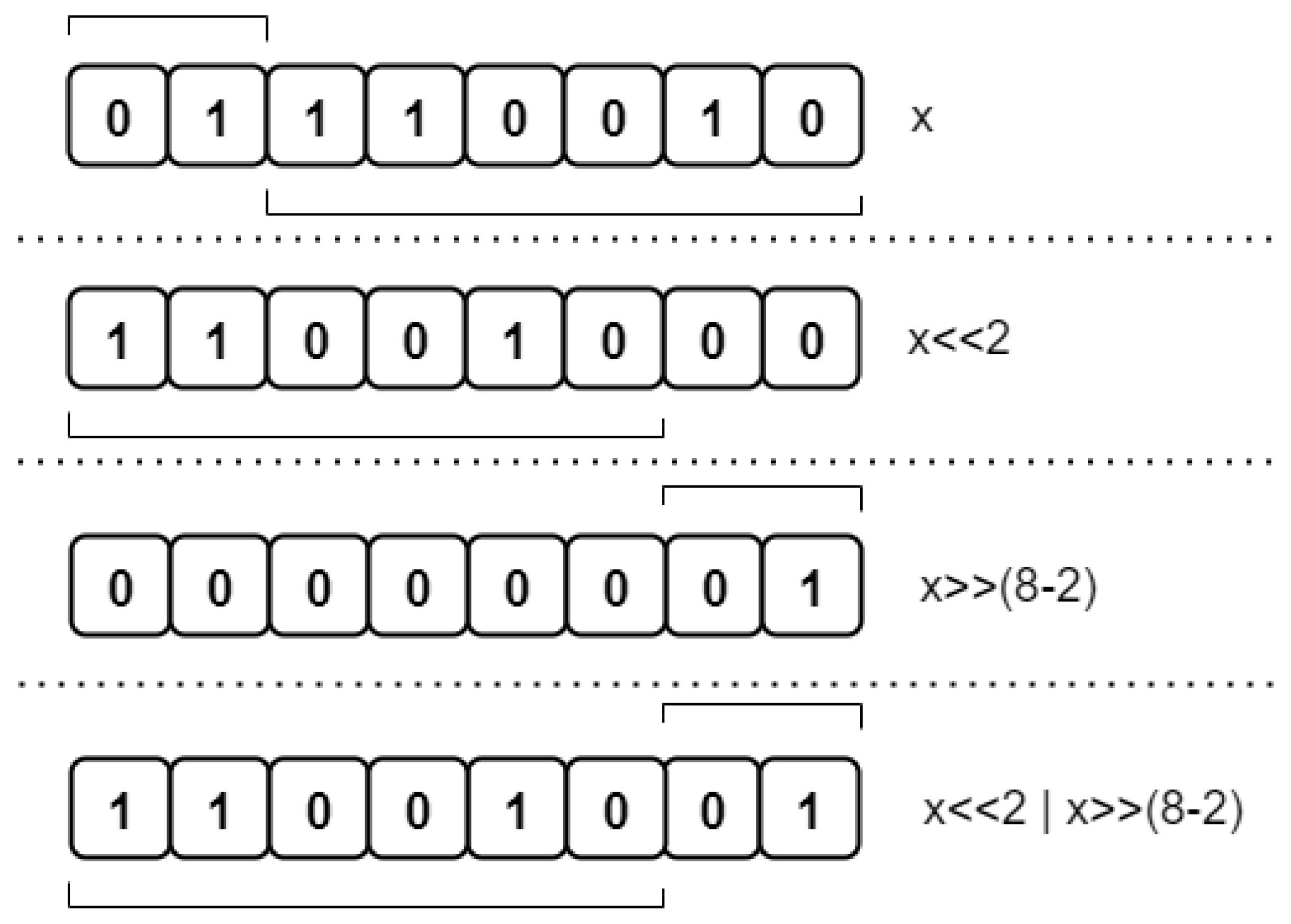
  • A circular shift of an identity matrix by s i , j ; then it can easily be verified that P s i , j u j T is a circular shift of u j T by s i , j positions.
Therefore, computing (10) for QC-LDPC codes requires elementary operations of circular shifts of subvectors of u T of length P, as well as modulo-2 additions of subvectors of length P, which are equivalent to additions over GF ( 2 ) . Similar elementary operations can be indicated for the other sparsely structured matrices by vector multiplications in Figure 2.
The T 1 by vector multiplication, e.g., b T : = T 1 a T , can be realized due to the equivalency:
b T = T 1 a T T b T = a T
which, in the matrix form, is expressed as
P 0 0 0 0 P s 2 , ( J I + g + 1 ) P 0 0 0 P s ( I g ) , ( J I + g + 1 ) P s ( I g ) , ( J I + g + 2 ) P s ( I g ) , ( J I + g + 3 ) P 0 · b 1 T b 2 T b I L T = a 1 T a 2 T a I L T
Examining (12), it can be noticed that subvectors b 1 , b 2 , can be subsequently computed. First, b 1 is computed according to:
P 0 b 1 T = a 1 T b 1 T = a 1 T
Then, b 2 is computed according to:
P s 2 , ( J I + g + 1 )   b 1 T + P 0 b 2 T = a 2 T b 2 T = ( P s 2 , ( J I + g + 1 ) ) b 1 T + a 2 T
and then every subsequent ith subvector b i T is computed according to the following expression:
P s i , ( J I + g + 1 )   b 1 T + P s i , ( J I + g + 2 ) b 2 T + + P 0 b i T = a i T b i T = P s i , ( J I + g + 1 )   b 1 T + P s i , ( J I + g + 2 )   b 2 T + + P s i , ( J I + g + i 1 )   b i 1 T + a i T
This last expression shows that computing every subsequent subvector b i T requires only circular shift operations of previously calculated subvectors b 1 T , , b ( i 1 ) T and additions over GF ( 2 ) .
The subvector additions over GF ( 2 ) are equivalent to the vector-wise binary exclusive-or (XOR) operations. The last step of encoding, as shown in Figure 2, is assembling a code vector c as follows:
c =   u p 1 p 2
We can conclude that the whole encoding process can be partitioned into the following elementary operations:
  • Circular shift operations of subvectors of length P;
  • Subvector additions over GF ( 2 ) realized with XOR operations.
We remark that a classic encoding that employs a generator matrix can also be realized with just GF ( 2 ) additions, but the generator matrix representation is not sparse. Meanwhile, the presented formulation operates directly on a sparse parity-check matrix; therefore, many of the submatrices are all-zero, thus significantly reducing the computational complexity.
All vectors computed as intermediate results and their sizes are summarized in Table 1. During the operation of the encoding algorithm, the system RAM can be dynamically interchanged for the storage of the intermediate vectors; for example, after step 2, vectors a and c are memorized, after step 3, vectors a , b , and c are memorized, and so on, as can be easily read in Figure 2. It can be verified that the greatest memory consumption is after step 7, when the following vectors are memorized: a , g , p 1 , and u . The memory utilization is quantified by experimental results in the next section.

5.2. Parity-Check Matrix Representations in Memory

Basically, three different representation methods can be considered. The first method is the direct representation with a Boolean variable table storing the binary parity-check matrix, as shown on the left side of Figure 3 (basic representation). Direct parity-check matrix storage would require an unnecessarily large amount of memory, e.g., 524,288 B for a 512 × 1024 matrix.
The second method is an index representation, in which indexes of nonzero elements in every row are memorized, which is shown in the middle of Figure 3, where 1 indicates a lack of nonzero indexes in the macro-column. The third method is the representation of circular shift values, as shown on the right side of Figure 3 (efficient QC-LDPC), where all-zero matrices are indicated by 1 and non-zero CPMs are represented by their cyclic shift values, which are stored in an integer table.
We claim that the third (shift values) representation is the most suitable for our implementation, not only because it utilizes memory efficiently, but also because it explicitly defines the circular shift values introduced in the previous section as the components of elementary encoding operations in the described algorithm.

5.3. Implementation of Elementary Operations

The elementary operations of the circular shift of QC-LDPC encoding algorithm can be implemented in the C language by using a bit-wise shift operation and bit-wise OR operation, as in the following example:
Applsci 12 02558 i001
where offset is the cyclic shift value and size is equivalent to the submatrix size P.
Using this instruction for the circular shift, the input value needs to be of the uint32_t type (if P 32 ), while the size and offset can usually be of the uint8_t type. The output value is in the same format as the input. An example for shifting 8-bit values with offset 2 is presented in Figure 4.
The possible circular shift is limited to P 32 , because the typical microcontrollers use 32-bit cores, and hence the elementary operations are efficiently executed for up to 32b subvector sizes. However, this limitation does not influence the achievable performance, because the LDPC codes with short-to-moderate submatrix sizes can be optimized at least as effectively as the codes with greater submatrix sizes if the codeword length remains the same [24].
The second elementary operation, the addition of the GF ( 2 ) subvectors, can be realized directly with an XOR operator in the C language applied to variables representing the subvectors.

5.4. Microcontroller Implementation Issues

We implemented the encoder for LDPC codes with a broad range of code vector and information vector sizes ( N , K ) . The encoder operates according to the block diagram shown previously in Figure 2.
The algorithm implemented in the microcontroller (the low-power STM32L476 mentioned above was used in the experimental design) was divided into four parts: input data preparation, two parts for calculating the p 1 and p 2 vectors, and the output assembly. The parity-check matrix H was divided into A , B , T , C , D , and E for the LDPC and QC-LDPC encoding, and this way, it was stored in the memory. For the experimental comparison, we implemented encoding for both LDPC codes with index representation and for QC-LDPC with cyclic shift representation. The H matrix was a constant initialized variable and was stored in flash memory.
In the first part of the algorithm, data were prepared to start the encoding procedure. The information vector u is a parameter of the encoding function and stored in the stack; likewise, every buffer and variable during the encoding process is stored in stack memory in the RAM. The available RAM memory in the current microcontroller is 128 KB; thus, the operations needed to use memory efficiently. The buffer usage was minimized; in most cases, one main and one temporary buffer were used to execute the operations.

6. Numerical Results

Our research is supported by the experimental results, which cover three aspects: memory utilization, encoding time, and error-correction performance. The optimized memory enables the use of smaller, lower-cost, and more energy-efficient microcontroller devices; optimized timing can potentially decrease energy consumption, and likewise, the error-correction performance, which is greater than in the case of typical block codes, can enable lower transmission power in wired or wireless transmission systems.
The QC-LDPC codes used for encoder verification and system performance simulation were obtained with a code graph optimization method, consisting of two phases:
  • Base graph construction, that is, a graph corresponding to the I × J base matrix W indicating non-zero submatrices in H in (1).
  • Cyclic lifting of the base graph, with cyclic shift values s i , j in (1) obtained with an iterative search algorithm.
The code construction algorithm is summarized as Algorithm 1.
Several different parity-check matrices ( H 1 , , H 8 ) with diversified block lengths, regular and irregular, as listed in Table 2, were used for the experimental study. For example, the parity-check matrix of a regular ( 3 , 6 ) , ( 1024 , 512 ) code with submatrix size P = 32 is provided in Figure 5. This matrix, referred to as H1 in Table 2, corresponds to an optimized graph, free of length-4 and length-6 cycles and a minimized number of length-8 cycles.
Algorithm 1. QC-LDPC parity-check matrix construction.
Input:
Base matrix size I × J , submatrix size P, variable nodes degree distribution λ = [ λ 2 , λ 3 , , λ d V max ]
Output:
Binary matrix H I P × J P consisting of I × J circulants of size P × P
  • {Base matrix construction}
  • If possible (that is, if λ 2 I / J ), insert dual diagonal at the right side of the base matrix W .
  • Utilizing the PEG algorithm [20], progressively add edges into the base graph (ones into the remaining part of W ), subject to the degree distribution λ .
  • {Cyclic shift values determination}
  • If W is not dual diagonal, then by row and column permutations, convert it to the ALT (almost lower triangular) form.
  • If W is dual diagonal, then fix the cyclic shift values on dual diagonal such that Φ = I , according to the expressions in [45].
  • In the base graph corresponding to W , identify all short closed walks (if the length of the shortest cycle is g, then closed walks up to length at least g + 4 should be identified).
  • For every closed walk, formulate a condition involving cyclic shift values s i , j such that corresponding cycles in the lifted code graph do not exist [24].
  • For every condition, iteratively modify associated s i , j values in order to satisfy the greatest possible number of conditions for the non-existence of corresponding cycles.
  • {Matrix construction}
  • From the obtained W and s i , j , i = 1 , , I , j = 1 , , J , construct H as in (1).
The parameters of the RS and BCH codes, which are counterparts of LDPC H 1 , , H 8 , are also presented in Table 2. These codes were used for an experimental comparison of the developed QC-LDPC scheme with classical block codes. Every RS code is clearly defined by its ( N , K ) parameters and for BCH codes, we also provide the correction capability parameter t B C H , defined as in [49]. The generator polynomials of RS and BCH codes are obtained as described in [49].
The RS encoder we use for comparison is a byte-size (8 bit) LSFR (linear-feedback shift register) implementation, following the source codes provided in [50], while the BCH encoder we base on the description provided in [51].
The encoding process in each algorithm is based on three steps: data preparation, encoding algorithm execution and storing the results. The encoding in all cases is based mostly on operations: XOR, OR and register shift. The basic LDPC, RS and BCH algorithms need to execute a similar order of the number of operations. Meanwhile, the inherent advantage of QC-LDPC is due to the following reasons:
  • The encoding combines operation for a blocks of P bits because multiplication by a whole submatrix can be done in a single shift operation;
  • The QC-LDPC parity-check matrix, which can be used directly for encoding, is by definition sparse; therefore, the number of multiplications by submatrices is also relatively small.
This explains the reduction in time processing, which is shown in the following results.

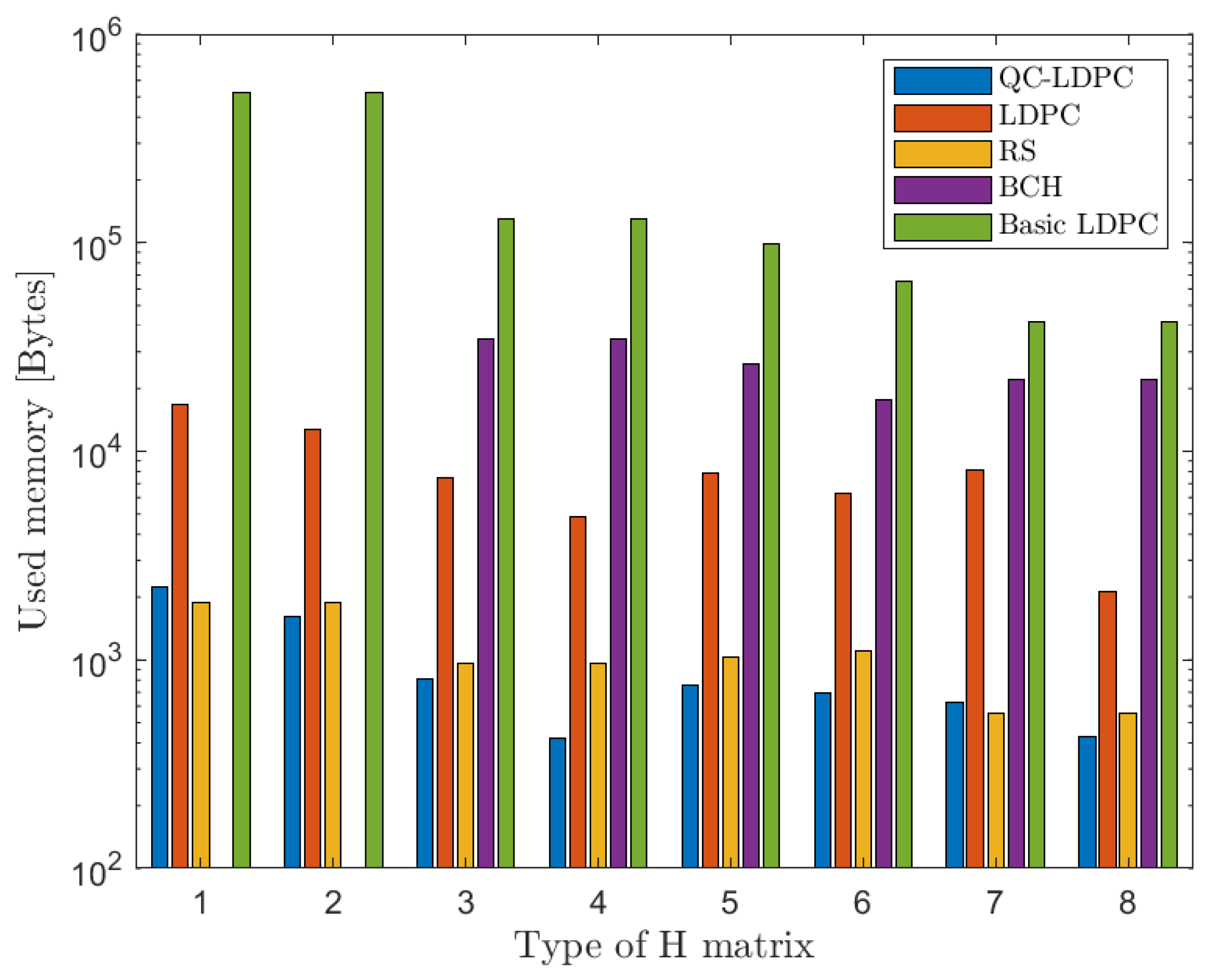
6.1. Memory Utilization

Figure 6 shows the memory utilization observed in our experimental framework for eight different LDPC parity-check matrices (H1, …, H8), as well as their Reed–Solomon (RS) and Bose–Chaudhuri–Hocquenghem (BCH) counterpart block codes (with similar block lengths and code rates R). Three LDPC encoder implementation methods were investigated. The basic implementation refers to the direct H matrix stored in the Boolean table. The memory requirement is too huge to be applicable with the STM32 device mentioned here due to the stack overflow error.
The second solution, referred to as an efficient LDPC, is based on the index representation of the H matrix and the developed encoding algorithm written in the C programming language. The algorithm is versatile. The memory utilization is roughly 20 times less than with the basic representation.
Finally, the third solution, marked with the blue bar in Figure 6, involves the developed QC-LDPC encoding algorithm and the circular shift value representation of H . This algorithm is available to encode only QC-LDPC parity-check matrices, but with a broad range of code lengths and rates. The significant memory reduction in the proposed solution was confirmed by the experimental results. It can also be observed that the memory utilization was not greater than that of the RS encoder counterpart implemented with the same microcontroller equipment. In all the presented charts, the proposed encoder is shortly denoted as QC-LDPC, while the index representation solution is denoted as LDPC.

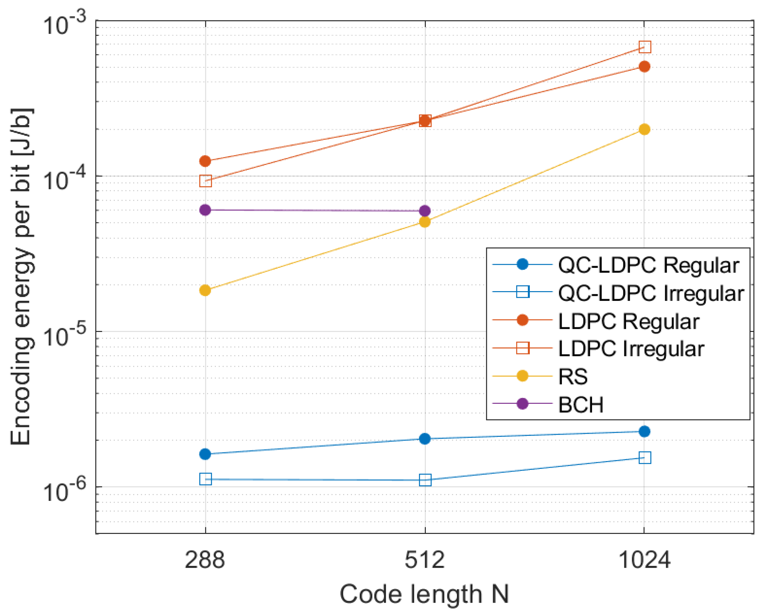
6.2. Block Encoding Time

A similar comparison was made for the encoding time measurements. Figure 7 presents the total encoding time of a single block for different parity-check matrices. The measured time involved the data preparation, calculation of parity bits p 1 , p 2 , and gathering of the output vector. We included results for standard LDPC encoding with the index representation (orange bar), as well as the proposed efficient QC-LDPC encoding (blue bar). A significant encoding time reduction was visible in the case of the developed efficient QC-LDPC algorithm implementation in comparison with the LDPC with the index matrix representation, as well as the Reed–Solomon (RS) encoders. This implementation thus has potential for the reduction in energy consumption in solutions that use sleep modes after the communication of a message from an IoT node. The relation of the working mode time to the sleep mode time can be reduced if the block encoding time is reduced.
Basing on the timing measurements, we estimated that energy saving that can be achieved for the proposed encoder in comparison with the Reed–Solomon encoding. For this estimation, the following assumptions were made, reflecting real operation of the microcontroller STM32 used for experiments:
  • The voltage supplied to the circuit is 3.6 V.
  • The current in the active mode with 80 MHz clock is 33.5 mA.
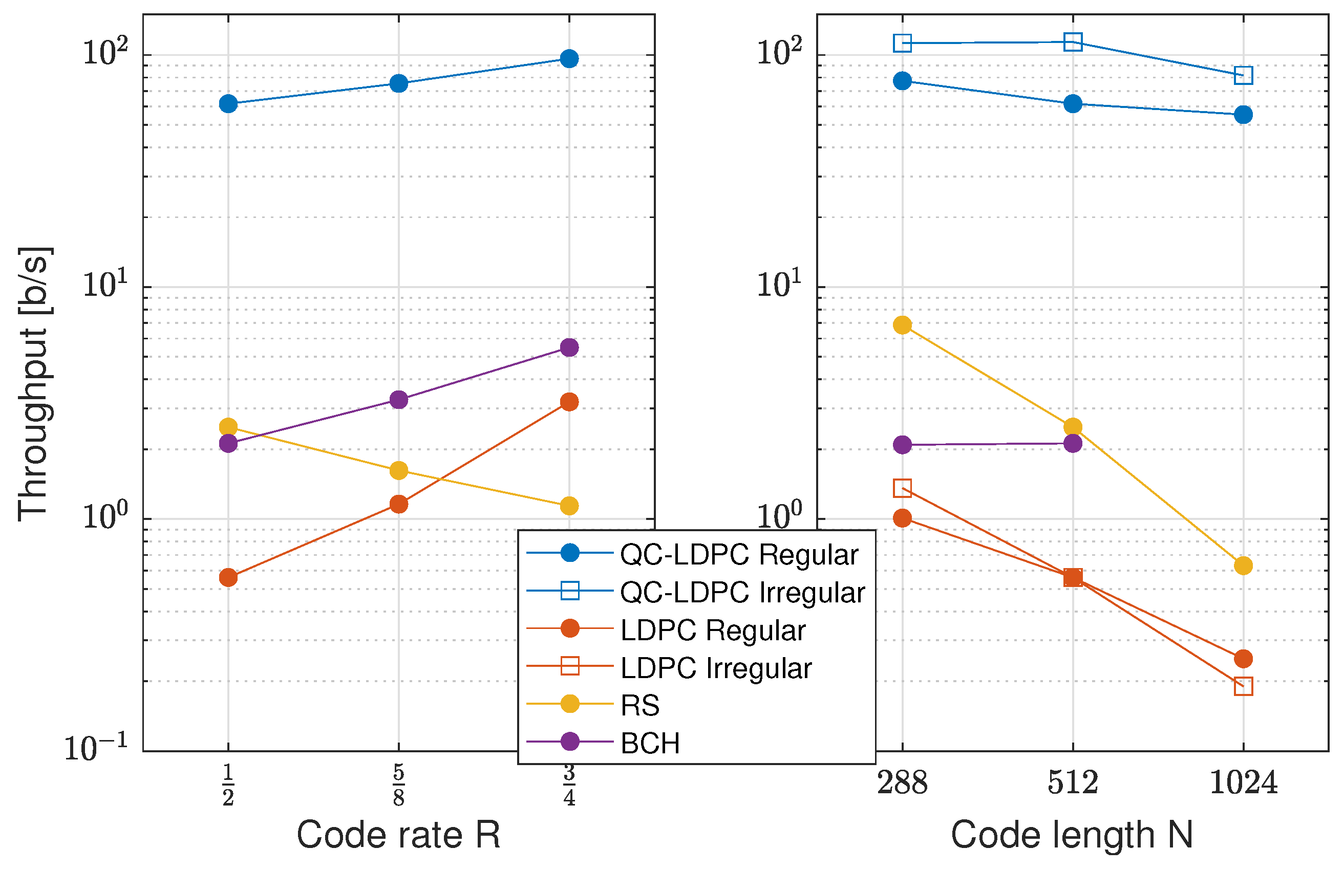
We calculated the normalized energy needed for encoding a single bit of the QC-LDPC codes as well as the other reference encoders. The results are presented in Figure 8. Then, we subtracted the results, obtaining the potential saving that can be achieved, expressed in μ J / bit . These results are presented in Table 3.

6.3. Throughput

The trade-offs between code parameters and the achieved encoder features can be also illustrated by means of the achieved maximum encoding throughput. This is visualized in Figure 9. We can observe the advantage of the proposed efficient QC-LDPC encoder realization over the basic LDPC, BCH and RS encodings. The throughput developed realization is rather not sensitive to the block length. The throughput in general increases with the code rate, because the portion of information bits in the code blocks increases.

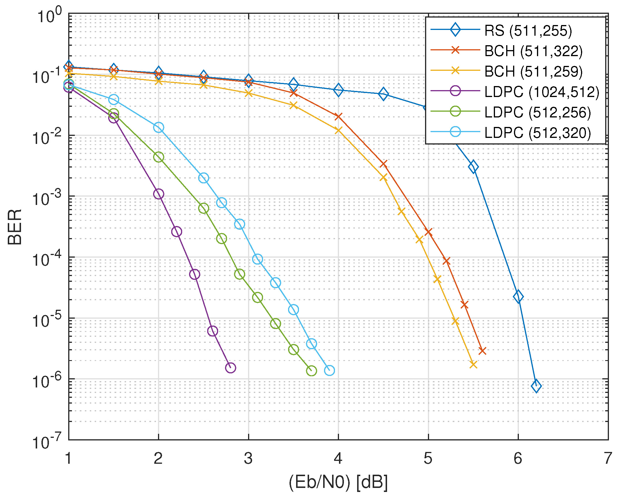
6.4. Error-Correction Performance

In order to show the coding gain that can be achieved with the QC-LDPC codes employed in comparison with typical classic block codes, we performed Monte Carlo simulations for the QC-LDPC codes, as well as for their RS and BCH counterparts. RS codes with rate R = 0.5 , BCH and QC-LDPC codes with different block lengths were used for this comparison. A QPSK modulator and an AWGN channel model were used in the communication system models. The LDPC codes were decoded with a belief propagation (BP) decoder, the BCH codes were decoded with the hard-decision Berlekamp algorithm, and the RS codes were decoded using the Berlekamp–Massey decoding algorithm.
Figure 10 presents the results of these experiments in the form of the bit error rate curve versus the effective signal-to-noise ratio ( E b / N 0 ) in an AWGN channel for three selected cases: (1024, 512), (512, 256), and (512, 320) LDPC codes and their counterparts, as shown in Table 2. An additional coding gain of about 2 dB for the QC-LDPC codes is visible in all of the presented cases. This result represents the amount of transmission power that can be saved when using iteratively decoded QC-LDPC codes instead of standard block codes.

7. Discussion

The ECC-encoding procedure presented in this paper is devoted to error protection in IoT node devices constructed with microcontroller-type equipment and without strict throughput requirements, but with the energy efficiency being an important factor. We showed that QC-LDPC codes, which are usually considered for high-throughput communication systems and advanced protocols can also be considered for these types of computationally constrained devices. We provided Richardson–Urbanke LDPC encoding expressed for QC-LDPC codes, and we showed how the encoding can be decomposed into elementary operations that are suitable for implementation in a simple microcontroller device.
The whole encoding algorithm was implemented and verified for a few QC-LDPC parity-check matrices. Comparisons with other known block codes (RS and BCH) are also provided, showing that the memory requirements are not greater than for standard block codes, while the achievable throughput is increased and the encoding time is reduced, which enables the energy consumption reduction. At the same time, the error-correction performance of LDPC codes is significantly better than for standard block codes. This provides the potential for the reduction in the energy consumption of the communication links used to connect IoT nodes with IoT gateways.

Author Contributions

Conceptualization, J.H. and W.S.; methodology, J.H. and W.S.; software, J.H.; validation, J.H., W.S., W.I., L.D. and W.F.; experimental investigation, J.H., W.S., W.I., L.D. and W.F.; data acquisition, J.H., W.S., W.I., L.D. and W.F.; writing, J.H., W.S., W.I., L.D. and W.F.; supervision, W.S. All authors have read and agreed to the published version of the manuscript.

Funding

This research was co-financed by the Ministry of Education and Science of Poland under grant No. DWD/3/7/2019 as well as SUBB.

Institutional Review Board Statement

Not applicable.

Informed Consent Statement

Not applicable.

Conflicts of Interest

The authors declare no conflict of interest.

References

  1. Swamy, S.N.; Kota, S.R. An Empirical Study on System Level Aspects of Internet of Things (IoT). IEEE Access 2020, 8, 188082–188134. [Google Scholar] [CrossRef]
  2. Dubal, V.A.; Rao, Y.S. A Low-Power High-Performance Sensor Node for Internet of Things. In Proceedings of the IEEE Second International Conference on Intelligent Computing and Control Systems (ICICCS), Madurai, India, 14–15 June 2018; pp. 607–612. [Google Scholar]
  3. Rajasekaran, C.; Raguvaran, K. Microcontroller Based Reconfigurable IoT Node. In Proceedings of the IEEE 4th International Conference on Frontiers of Signal Processing, Poitiers, France, 24–27 September 2018; pp. 12–16. [Google Scholar]
  4. Berrou, C.; Glavieux, A.; Thitimajshima, P. Near Shannon Limit Error-Correcting Coding and Decoding: Turbo-Codes. In Proceedings of the (IEEE) International Conference on Communications, Geneva, Switzerland, 23–26 May 1993; pp. 1064–1070. [Google Scholar]
  5. Arikan, E. Channel Polarization: A Method for Constructing Capacity-Achieving Codes for Symmetric Binary-Input Memoryless Channels. IEEE Trans. Inf. Theory 2009, 55, 3051–3073. [Google Scholar] [CrossRef]
  6. Gallager, R. Low-density parity-check codes. IRE Trans. Inf. Theory 1962, 8, 21–28. [Google Scholar] [CrossRef] [Green Version]
  7. MacKay, D.J.C. Good Error-Correcting Codes Based on Very Sparse Matrices. IEEE Trans. Inf. Theory 1999, 45, 399–431. [Google Scholar] [CrossRef] [Green Version]
  8. Condo, C. VLSI Implementation of a Multi-ModeTurbo/LDPC Decoder Architecture. IEEE Trans. Circuits Syst. I 2013, 60, 1441–1454. [Google Scholar] [CrossRef]
  9. Nguyen, T.T.B.; Tan, T.N.; Lee, H. Low-Complexity High-Throughput QC-LDPC Decoder for 5G New Radio Wireless Communication. Electronics 2021, 10, 1–18. [Google Scholar]
  10. Zhu, Y.; Xing, Z.; Li, Z.; Zhang, Y.; Hu, Y. High Area-Efficient Parallel Encoder with Compatible Architecture for 5G LDPC Codes. Symmetry 2021, 13, 700. [Google Scholar] [CrossRef]
  11. Hailes, P.; Xu, L.; Maunder, R.G.; Al-Hashimi, B.M.; Hanzo, L. A Survey of FPGA-Based LDPC Decoders. IEEE Commun. Surv. Tutor. 2015, 18, 1098–1122. [Google Scholar] [CrossRef] [Green Version]
  12. Luo, H.; Zhang, Y.; Li, W.; Huang, L.K.; Cosmas, J.; Li, D.; Maple, C. Low Latency Parallel Turbo Decoding Implementation for Future Terrestrial Broadcasting Systems. IEEE Trans. Broadcast. 2018, 64, 96–104. [Google Scholar] [CrossRef] [Green Version]
  13. Lazarenko, A. FPGA Design and Implementation of DVB-S2/S2X LDPC Encoder. In Proceedings of the IEEE International Conference on Electrical Engineering and Photonics, St. Petersburg, Russia, 17–18 October 2019; pp. 98–102. [Google Scholar]
  14. Petrović, V.L.; El Mezeni, D.M.; Radošević, A. Flexible 5G New Radio LDPC Encoder Optimized for High Hardware Usage Efficiency. Electronics 2021, 10, 1106. [Google Scholar] [CrossRef]
  15. Tarver, C.; Tonnemacher, M.; Chen, H.; Zhang, J.; Cavallaro, J.R. GPU-Based, LDPC Decoding for 5G and Beyond. IEEE Open J. Circuits Syst. 2021, 2, 278–290. [Google Scholar] [CrossRef]
  16. Liao, S.; Zhan, Y.; Shi, Z.; Yang, L. A High Throughput and Flexible Rate 5G NR LDPC Encoder on a Single GPU. In Proceedings of the IEEE International Conference on Advanced Communications Technology (ICACT), Pyeongchang-gun, Korea, 7–10 February 2021; pp. 29–34. [Google Scholar]
  17. Richardson, T.J.; Shokrollahi, M.A.; Urbanke, R.L. Design of Capacity-Approaching Irregular Low-Density Parity-Check Codes. IEEE Trans. Inf. Theory 2001, 47, 619–637. [Google Scholar] [CrossRef] [Green Version]
  18. Kelley, C.A.; Deepak, S. Pseudocodewords of Tanner Graphs. IEEE Trans. Inf. Theory 2007, 53, 4013–4038. [Google Scholar] [CrossRef]
  19. Divsalar, D.; Dolinar, S.; JoJones, C.R.; Andrews, K. Capacity-Approaching Protograph Codes. IEEE J. Sel. Areas Commun. 2009, 27, 876–888. [Google Scholar] [CrossRef]
  20. Hu, X.Y.; Eleftheriou, E.; Arnold, D.M. Regular and Irregular Progressive Edge-Growth Tanner Graphs. IEEE Trans. Inf. Theory 2005, 51, 386–398. [Google Scholar] [CrossRef]
  21. Gholami, M.; Raeisi, G. Large Girth Column-Weight Two and Three LDPC Codes. IEEE Commun. Lett. 2014, 18, 1671–1674. [Google Scholar] [CrossRef]
  22. Bocharova, I.E.; Kudryashov, B.; Johannesson, R. Searching for Binary and Nonbinary Block and Convolutional LDPC Codes. IEEE Trans. Inf. Theory 2016, 62, 163–183. [Google Scholar] [CrossRef]
  23. Tasdighi, A.; Banihashemi, A.H.; Sadeghi, M.R. Symmetrical Constructions for Regular Girth-8 QC-LDPC Codes. IEEE Trans. Commun. 2017, 52, 1242–1247. [Google Scholar] [CrossRef]
  24. Sulek, W. Protograph Based Low-Density Parity-Check Codes Design with Mixed Integer Linear Programming. IEEE Access 2019, 7, 1424–1438. [Google Scholar] [CrossRef]
  25. Sulek, W.; Kucharczyk, M. Partial parallel encoding and algorithmic construction of non-binary structured IRA codes. China Commun. 2016, 13, 103–116. [Google Scholar] [CrossRef]
  26. Fossorier, M.P.C.; Mihaljevic, M.; Imai, H. Reduced Complexity Iterative Decoding of Low-Density Parity Check Codes Based on Belief Propagation. IEEE Trans. Commun. 1999, 47, 673–680. [Google Scholar] [CrossRef]
  27. Li, J.; Liu, K.; Lin, S.; Abdel-Ghaffar, K. Algebraic Quasi-Cyclic LDPC Codes: Construction, Low Error-Floor, Large Girth and a Reduced-Complexity Decoding Scheme. IEEE Trans. Commun. 2014, 62, 2626–2637. [Google Scholar] [CrossRef]
  28. Stark, M.; Lewandowsky, J.; Bauch, G. Information-Bottleneck Decoding of High-Rate Irregular LDPC Codes for Optical Communication Using Message Alignment. Appl. Sci. 2018, 10, 1884. [Google Scholar] [CrossRef] [Green Version]
  29. Marques da Silva, M.; Dinis, R.; Martins, G. On the Performance of LDPC-Coded Massive MIMO Schemes with Power-Ordered NOMA Techniques. Appl. Sci. 2021, 11, 8684. [Google Scholar] [CrossRef]
  30. Lin, C.F. UFMC-Based Underwater Voice Transmission Scheme with LDPC Codes. Appl. Sci. 2021, 11, 1818. [Google Scholar] [CrossRef]
  31. Sulek, W. Pipeline processing in low-density parity-check codes hardware decoder. Bull. Pol. Acad. Sci. Tech. Sci. 2011, 59, 149–155. [Google Scholar]
  32. Mahdi, A.; Paliouras, V. A Low Complexity-High Throughput QC-LDPC Encoder. IEEE Trans. Signal Process. 2014, 62, 2696–2708. [Google Scholar] [CrossRef]
  33. Huang, J.; Zhou, S.; Willett, P. Nonbinary LDPC Coding for Multicarrier Underwater Acoustic Communication. IEEE J. Sel. Areas Commun. 2008, 26, 1684–1696. [Google Scholar] [CrossRef]
  34. Boutillon, E.; Conde-Canecia, L.; Ghouwayel, A.A. Design of a GF(64)-LDPC Decoder Based on the EMS Algorithm. IEEE Trans. Circuits Syst. I 2013, 60, 2644–2656. [Google Scholar] [CrossRef] [Green Version]
  35. Sulek, W. Non-binary LDPC Decoders Design for Maximizing Throughput of an FPGA Implementation. Circuits Syst. Signal Process. 2016, 35, 4060–4080. [Google Scholar] [CrossRef]
  36. Zhao, S.; Ma, X. Construction of High-Performance Array-Based Non-Binary LDPC Codes with Moderate Rates. IEEE Commun. Lett. 2016, 20, 13–16. [Google Scholar] [CrossRef]
  37. IEEE Standard: IEEE P802.16; Local and Metropolitan Area Networks Part 16: Air Interface for Fixed and Mobile Broadband Wireless Access Systems. IEEE: Piscataway, NJ, USA, 2006.
  38. IEEE 802.11-2016; IEEE Standard for Information Technology–Telecommunications and Information Exchange between Systems Local and Metropolitan Area Networks–Specific Requirements—Part 11: Wireless LAN Medium Access Control (MAC) and Physical Layer (PHY) Specifications. IEEE: Piscataway, NJ, USA, 2016.
  39. 3GPP TS 38.212 Version 16.2.0 Release 16. Multiplexing and Channel Coding; 5G; NR; ETSI: Sophia Antipoli, France, 2020. [Google Scholar]
  40. Theodoropoulos, D.; Kranitis, N.; Paschalis, A. An efficient LDPC encoder architecture for space applications. In Proceedings of the IEEE 22nd International Symposium on On-Line Testing and Robust System Design (IOLTS), Sant Feliu de Guixols, Spain, 4–6 July 2016; pp. 149–154. [Google Scholar]
  41. Nguyen, T.T.B.; Nguyen Tan, T.; Lee, H. Efficient QC-LDPC Encoder for 5G New Radio. Electronics 2019, 8, 668. [Google Scholar] [CrossRef] [Green Version]
  42. Wu, H.; Wang, H. A High Throughput Implementation of QC-LDPC Codes for 5G NR. IEEE Access 2019, 7, 185373–185384. [Google Scholar] [CrossRef]
  43. Richardson, T.J.; Urbanke, R.L. Efficient Encoding of Low-Density Parity-Check Codes. IEEE Trans. Inf. Theory 2001, 47, 638–656. [Google Scholar] [CrossRef] [Green Version]
  44. Fossorier, M.P.C. Quasi-Cyclic Low-Density Parity-Check Codes from Circulant Permutation Matrices. IEEE Trans. Inf. Theory 2004, 50, 1788–1793. [Google Scholar] [CrossRef] [Green Version]
  45. Myung, S.; Yang, K.; Kim, J. Quasi-Cyclic LDPC Codes for Fast Encoding. IEEE Trans. Inf. Theory 2005, 51, 2894–2901. [Google Scholar] [CrossRef]
  46. Tanner, R.M. A Recursive Approach to Low Complexity Codes. IEEE Trans. Inf. Theory 1981, IT-27, 533–547. [Google Scholar] [CrossRef] [Green Version]
  47. Tasdighi, A.; Banihashemi, A.H.; Sadeghi, M.R. Efficient Search of Girth-Optimal QC-LDPC Codes. IEEE Trans. Inf. Theory 2016, 62, 1552–1564. [Google Scholar] [CrossRef]
  48. Xu, H.; Feng, D.; Luo, R.; Bai, B. Construction of Quasi-Cyclic LDPC Codes via Masking with Successive Cycle Elimination. IEEE Commun. Lett. 2016, 20, 2370–2373. [Google Scholar] [CrossRef]
  49. Lin, S.; Costello, D.J., Jr. Error Control Coding: Fundamentals and Applications, 2nd ed.; Prentice-Hall, Inc.: Upper Saddle River, NJ, USA, 2004. [Google Scholar]
  50. RSCODE Project. Available online: http://rscode.sourceforge.net (accessed on 3 October 2021).
  51. Generic Binary BCH Encoding/Decoding Library. Available online: https://github.com/Parrot-Developers/bch. (accessed on 14 January 2022).
Figure 1. General architecture of IoT communication using LDPC codes for the error correction.
Applsci 12 02558 g001
Figure 2. Block diagram presenting consecutive steps in the efficient encoding algorithm.
Applsci 12 02558 g002
Figure 3. Illustration of the size of the H matrix with three different representations in the microcontroller memory.
Applsci 12 02558 g003
Figure 4. Example of a circular shift operation.
Applsci 12 02558 g004
Figure 5. Parity-check matrix of a (1024,512) QC-LDPC code with submatrix size P = 32 . The cyclic shift values are provided for non-zero submatrices.
Applsci 12 02558 g005
Figure 6. Memory utilization of the implemented encoders.
Applsci 12 02558 g006
Figure 7. Single block encoding time periods.
Applsci 12 02558 g007
Figure 8. Encoding energy needed per bit vs. code length.
Applsci 12 02558 g008
Figure 9. Throughput of the encoders vs. code parameters.
Applsci 12 02558 g009
Figure 10. Error correction performance of the experimental codes.
Applsci 12 02558 g010
Table 1. Comparison of intermediate computation vector sizes.
VectorLengthVectorLength
a ( I g ) P u ( J I ) P
b g P g ( I g ) P
c g P h ( I g ) P
d g P p 1 g P
e g P p 2 ( I g ) P
Table 2. Parameters of the experimental parity-check matrices H for LDPC. The λ d represents the fraction of degree-d variable nodes in the code graph.
MatrixKNPRDistribution N RS , BCH K RS R RS K BCH t BCH R BCH
H1512102432 1 2 Reg., λ 3 = 1 1023511 1 2 ---
H2512102432 1 2 Irreg., λ 2 , 3 , 7 1023511 1 2 ---
H325651232 1 2 Reg., λ 3 = 1 511255 1 2 25930 1 2
H425651232 1 2 Irreg., λ 2 , 3 , 6 511255 1 2 25930 1 2
H532051232 5 8 Reg., λ 3 = 1 511321 5 8 32222 5 8
H638451232 3 4 Reg., λ 3 = 1 511383 3 4 38514 3 4
H714428816 1 2 Reg., λ 3 = 1 255143 1 2 14714 1 2
H814428816 1 2 Irreg., λ 2 , 3 , 6 255143 1 2 14714 1 2
Table 3. Energy savings per bit, achieved for QC-LDPC encoding, in comparison with counterpart Reed–Solomon encoding.
Matrix IDEnergy Saved
[ μ J/bit]
Matrix IDEnergy Saved
[ μ J/bit]
H1196.81H2197.55
H348.65H449.59
H576.29H6108.94
H716.75H817.26
Publisher’s Note: MDPI stays neutral with regard to jurisdictional claims in published maps and institutional affiliations.

