Abstract
Icings on moving machinery, such as wind turbines and aircraft wings, degrade their performance and safety. Ultrasonic vibration is considered one of the deicing methods. In this research, simulations and experiments are carried out to explore the effect of ultrasonic vibration on the adhesive characteristic of ice on aluminum alloy plates. Harmonic response analyses are conducted to analyze the changing and distributions of shear stresses at the adhesive interface under different frequencies and sizes of PZT patches. The results show that there is optimum side length and thickness of the PZT patch, as the size of the iced aluminum alloy plate is constant. In these conditions, the shear stresses at the adhesive interface are high. Then, experiments on adhesive torque of ice are carried out to calculate the adhesive shear stresses of ice. The results show that the adhesive force of ice decreases under the excitation of ultrasonic vibration. When the excited frequency is 79 kHz, the adhesive torsional shear stress is 0.014 MPa, which is only 7% of the one with no ultrasonic vibration.
1. Introduction
In cold and humid environments, ice accretion often presents on the surfaces of rotating machinery, such as airplane wings and wind turbines, which degrades their performance and safety. For example, the icing on the surface of a wind turbine blade will change the airfoil profile and the weight of the blade, which are shown in Figure 1. As shown in Figure 1, ice accretion destroys the aerodynamic performance of the blade and reduces the power generation efficiency of the wind turbine. Meanwhile, it increases the weight of the blade, which shortens the life span of the wind turbine, and ice shedding threatens the safety of nearby people and buildings [1,2,3]. Similarly, the icing on the surface of the aircraft wing also reduces the reliability and safety of aircraft [4,5].
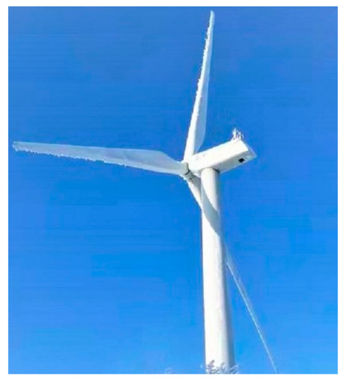
Figure 1.
Icing on wind turbine blades.
Li Yan [6,7,8] conducted an icing experiment of a wind turbine in a self-developed icing wind tunnel. The icing process and icing shape on the blade surface were examined, and an analysis method for the irregular icing shape was also proposed.
Yihua Cao [9,10] calculated the process of ice accretion on the aircraft wing by simulation. The above-mentioned research findings lay the theoretical and experimental foundations for exploring the anti-icing and deicing methods in depth. Therefore, decreasing the adhesive strength of the ice and removing the ice from the machinery surfaces have high application value.
At present, there are several kinds of methods being researched to reduce the adhesive strength of ice or remove it, including the electrothermal method, the fluid-thermal method, the pneumatic method, the electric-pulse method, the microwave method, the surface coating method, and the ultrasonic vibration method [11,12,13,14]. Among these deicing methods, the electrothermal and microwave methods consume a significant amount of energy, while the fluid-thermal and pneumatic impulse methods have huge volumes and complex systems. In the surface coating deicing method, the coating easily falls off from the surface after a short working time, leading to the surface losing its deicing ability. The system of the electric pulse deicing method is complicated due to the high distribution density of the coil. In contrast, the ultrasonic deicing method has the features of consuming low energy, small vibration amplitude, long lifetime, light weight, no noise, simple structure, and easy installation and, therefore, can be considered one of the better deicing methods, especially for wind turbines. However, the deicing mechanism of it has not been refined and developed right now. The fundamental principle of it is to reduce the adhesive strength of the ice by generating shear stress at the adhesive interface between the ice and the substrate under the excitation of ultrasonic vibration. When the shear stress is higher than the adhesive strength, the ice falls off. Habibi [15] calculated the interfacial stress concentration coefficient (ISCC) and the vibration amplitude at the adhesive interface under a low-frequency excitation of a guided wave, and the distribution of the shear stress was acquired. Zhu [16] tested the ISCC of the iced composite material with an erosion layer and researched the deicing effect of the ultrasonic vibration in an experiment. Palacios [17,18] simulated and tested the anti-icing and deicing effects of the ultrasonic vibration on an aluminum plate and the leading edge of an airplane wing in a wind tunnel. Zeng [19] investigated the deicing effect of ultrasonic vibration on independent lumpy ices on an aluminum plate using simulation and experiment. Haihui [20] explored the effects of shear stresses generated by ultrasonic vibration at the interface between the ice and the substrate through simulation and experiment. To maximize deicing efficiency, it is important to explore the effects of ultrasonic vibration on the adhesive characteristic of ice covering on the substrate surface. Currently, practical research methods to achieve this aim include simulation and experimental methods. The simulation method aims to calculate the vibration mode of a research object and the distribution of shear stresses at the adhesive interface. However, the distributing state of shear stress at the adhesive interface is seldom researched. Additionally, the experimental method is commonly used to measure the time length of deicing. In these experiments, most research objects are small lumpy ices on the substrate surfaces, and the time length of ice removal is selected as one of the key measuring parameters. However, in many real icing conditions, such as the icing conditions of wind turbines, the structure of the ice is not composed of independent lumpy ices but a whole continuous ice cover on the whole surface. This kind of ice is seldom selected as a research object, and the adhesive forces of the ice under different conditions, such as excitation frequency and the size of piezoelectric ceramic, are seldom measured. In our previous research, it was found that the thickness of the ice covering the whole aluminum alloy plate surface decreases under ultrasonic vibration, which has an anti-icing effect, but the ice is not removed at all [21]. Therefore, the adhesive force of the ice and the distributing state of shear stress at the adhesive interface, excited by ultrasonic vibration, need to be researched in depth.
In this paper, studies are carried out on the effect of ultrasonic variations on the surface adhesive characteristic of ice covering on aluminum alloy plates, under excitations of ultrasonic vibration, using simulation and experiment. The effect of ultrasonic vibration on the adhesive force of ice is measured and analyzed quantitatively. The location and size of an ultrasonic excitation source (PZT patch) are calculated by ANSYS. Then, the distribution law of shear stress at the interface between ice and substrate plate is simulated. In this way, the optimum distribution law is determined. Based on theoretical research findings, the adhesive force of the ice under the excitation of ultrasonic vibration is measured by a self-developed experimental system, and the adhesive shear strength of the ice is calculated by a self-established analytical model. All the research findings in this paper lay the theoretical and experimental foundations for exploring the ultrasonic deicing method in depth.
2. Simulation of the Location of Vibration Source
For the large-scale wind turbine, the blade surface can be simplified into two kinds of shapes—the curved surface and the plane surface, which are shown in Figure 2. For the blade body, the curvature of it is small. In the scope of a small area, we simplified the surface into a piece of the plane. In contrast, the leading edge of the blade has large curvature. It can be simplified into a volume surface in the scope of a small area. By this simplification method, the research process can be simplified, and fundamental research on the adhesive characteristics of icing on the plate and volume can also be carried out. In the present study, a plate element, not from the exact position of a real blade body, was selected as a research object characterizing part of the blade body, to carry out studies on the ultrasonic vibration deicing technology.
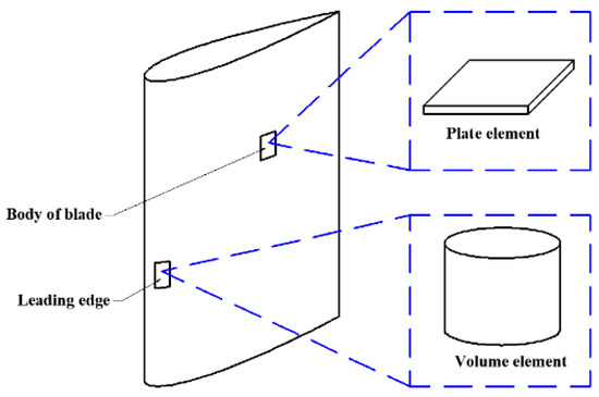
Figure 2.
Simplification model of the wind turbine blade.
The formation of ice is a phase change of water from liquid to solid as the temperature falls below zero degrees Celsius. After phase change, the ice is frozen together with the substrate material. Therefore, the iced body is similar to a composite material. In general, there are three basic categories of deicing systems, which are the mechanical deicing system, the thermal deicing system, and the chemical deicing system. For the mechanical deicing system, the principle of the deicing system is to break the adhesive bond [22]. Many years ago, researchers found that the adhesion strength of ice is lower in shear than in tension [23]. Similarly, in a previous study, it was also validated that the key factor of breaking the adhesive bond is shear stress [24]. Therefore, researchers selected shear stress as the deicing parameter for the mechanical deicing system. In this paper, the ultrasonic deicing method used is a mechanical deicing system. Its principle is shown in Figure 3a.
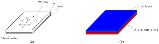
Figure 3.
Model of iced plate element for ultrasonic deicing: (a) principle of ultrasonic deicing; (b) model of iced aluminum alloy plate.
As shown in Figure 3a, when the PZT patch (piezoelectric ceramic) is excited by alternative voltage, it alternatively extends and contracts in ultrasonic frequency, which excites the iced aluminum alloy plate to vibrate and deform. Then, the mechanical shear stress generates due to bending deformation at the adhesive interface. When mechanical shear stress is higher than the adhesive shear stress of ice, the ice can be removed.
In this paper, an aluminum alloy was selected as the substrate material, because metals have the characteristics of isotropies in elasticity and heat transfer. Aluminum alloys have lower elastic moduli lower than other materials. They easily deform under the excitation of ultrasonic vibration, which is suited to conduct the basic research on ultrasonic deicing. In addition, many scholars have carried out studies on the adhesive characteristic of ice on aluminum alloy surfaces. The adhesive shear stress of ice covering on the aluminum alloy surface can be referenced and compared. In the present study, an aluminum alloy plate with the size of 60 mm × 60 mm × 2 mm was initially selected as a plate element, and the thickness of the ice is 2 mm. The model of the iced aluminum alloy plate is shown in Figure 3b.
According to the principle of the ultrasonic deicing method, while an iced aluminum alloy substrate deforms under the excitation of ultrasonic vibration, shear stress generates at the adhesive interface between the ice and the aluminum alloy plate. When the shear stress is higher than the adhesive shear stress of ice, which is the adhesive shear force in the unit area, the ice layer can be removed from the substrate plate. Therefore, in the present study, the bend deformation of the iced aluminum alloy plate was selected, which leads to higher shear stress at the adhesive interface between the ice and the aluminum alloy plate.
To determine the location of the piezoelectric ceramic (PZT-4), which is the ultrasonic vibration source, the first-order bending vibration mode of the iced aluminum alloy plate was calculated by ANSYS software. The element types of the ice and the aluminum alloy plate were both SOLID186. Material parameters of most series of aluminum alloy [25] and refrigerator ice [26], along with their mesh properties, are listed in Table 1.

Table 1.
Properties of materials.
In the simulation, edges of an iced aluminum alloy plate were fixed, which simulated the constrained condition of one iced plate element, because the body surface of a large-scale wind turbine blade was considered as a plane on the small scale, which is shown in Figure 2. As derived from Figure 2, the size of the plate element is too small in comparison with the whole blade surface, and its sides are constrained by the peripheral body of the blade. Therefore, the four sides of the ice aluminum alloy plate element were assumed to be fixed in the simulation. Additionally, the relationship between ice and aluminum alloy plate was coupled by the command of VGLUE. Based on the above simulation conditions, the first-order vibration mode is shown in Figure 4.
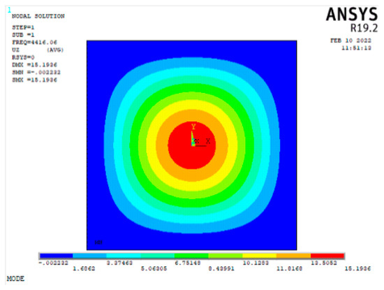
Figure 4.
Cloud image of the first-order vibration mode of the iced aluminum alloy plate.
For analyzing mesh sensitivity and accuracy, in this paper, modal analyses for an iced aluminum alloy plate were conducted. The iced aluminum alloy plate was meshed by a mapped method. The simulation results are shown in Figure 5.
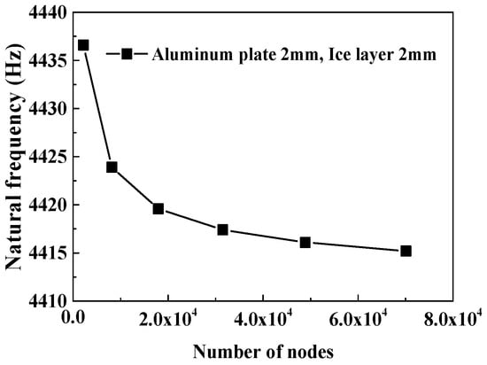
Figure 5.
Mesh sensitivity analysis.
As shown in Figure 5, the natural frequency decreases, first rapidly and then slowly, with the increase in the number of nodes. When the number of nodes changes from 2189 to 17,945, the variation in natural frequency is 17 Hz. In contrast, as the number of nodes increases from 17,945 to 70,089, the variation is just 4.4 Hz. In the present study, considering calculation accuracies and time length, the number of nodes selected was 31,529. In this case, each element size was 1.5 mm × 1.5 mm × 1 mm.
According to the modal analysis result, a piece of piezoelectric ceramic was adhered to the reverse side of the aluminum alloy substrate without ice, as shown in Figure 6. It is located at the center of the iced aluminum alloy plate, which is in the vicinity of the red region shown in Figure 4. At this position, the bending deformation of the iced aluminum alloy plate is easily generated by the excitation of the PZT patch. When the iced aluminum alloy plate bends, shear stress generates at the adhesive interface between the ice and the aluminum alloy plate.
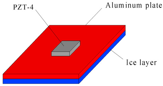
Figure 6.
Sketch map of the adhesive position of the piezoelectric ceramic.
3. Effect of PZT Patch Size on Shear Stress
According to the principle of the ultrasonic deicing method, ultrasonic vibration generates due to the inverse piezoelectric effect of piezoelectric ceramic. Therefore, the size of the PZT patch significantly affects the shear stress intensity at the adhesive interface. In this section, the effects of side length and thickness of piezoelectric ceramic on shear stress at the interface are investigated using a simulation method.
3.1. The Effect of Side Length
For exploring the effect of the side length of the PZT patch on shear stress at the adhesive interface, the variation in maximum shear stress at the adhesive interface with frequency was calculated and analyzed by harmonic response analysis for the iced aluminum alloy plate. An aluminum alloy material was selected, whose properties are listed in Table 1. The size of the aluminum alloy plate was 60 mm × 60 mm × 2 mm. The shape and the side length of the ice layer were the same as those of the aluminum alloy plate, and the thicknesses of the ice and piezoelectric ceramic were both 2 mm. The properties of ice are also listed in Table 1. The shape of the PZT patch was square, and the side length of the PZT patch was in the range of 12 mm~17 mm, which was decided according to the modal analysis results shown in Figure 4. As inferred from Figure 4, the largest vibration amplitude is in the central part of an iced aluminum alloy plate. Therefore, for maximum excitation of the bending deformation, the PZT patch is located in the central part. In this paper, the diameter of the red region was selected as the lower limit, and the diameter of the orange region was selected as the upper limit, which were 12 mm and 17 mm, respectively.
For the meshing process, a mapped method was used. The element types of the aluminum alloy plate and the ice were both SOLID186, and that of the PZT patch was SOLID226. The PZT patch was attached to the aluminum alloy plate by command VGLUE, which generated a common plane between the PZT patch and the aluminum alloy plate. By this command, the elements (SOLID226) of the PZT patch coupled with the elements (SOLID186) of the aluminum alloy plate.
The parameters of the PZT patch, including elastic matrix E, piezoelectric matrix e, and relative permittivity ε, were determined [27], and its density is 7.5 × 10³ kg/m3.
The elastic matrix E of piezoelectric ceramic, which is expressed in stiffness form, is expressed with the following matrix:
The piezoelectric matrix e is expressed with the following matrix:
The relative permittivity ε is expressed with the following matrix:
For electrical boundary conditions, a sinusoidal voltage was applied to the PZT patch. In the process of simulation, the voltage at the interface between the PZT patch and aluminum alloy plate was set to zero, and an alternative voltage was applied on the opposite surface of the PZT patch against the interface. The excitation voltage Vp-p loading on the PZT patch (peak to peak) was 400 V. The simulation results are shown in Figure 7.
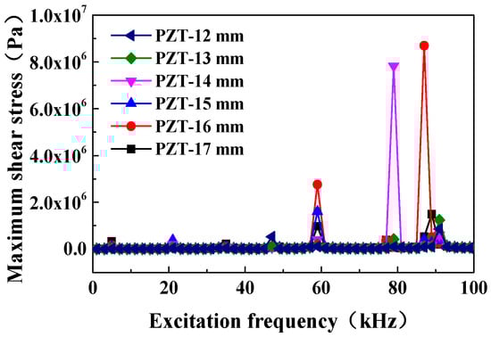
Figure 7.
Variations in maximum shear stress with excitation frequency and the side length of the PZT patch.
As shown in Figure 7, when the side length of the PZT patch is 16 mm × 16 mm or 14 mm × 14 mm, the maximum values of shear stress at the adhesive interface are high in both cases. Based on the existing research findings, the maximum adhesive shear stress of ice covering on metal substrates is about 1.8 × 10⁶ Pa [22]. Therefore, in the above simulation cases, there are three kinds of conditions satisfying the deicing condition. The parameters in these conditions and simulation results are listed in Table 2, and the cloud images of the distributions of shear stress at the adhesive interface under these conditions are shown in Figure 8.
Table 2.
Parameters and maximum shear stresses.
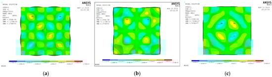
Figure 8.
Distributions of shear stress at the adhesive interface: (a) side length is 14 mm, and frequency is 79 kHz; (b) side length is 16 mm, and frequency is 87 kHz; (c) side length is 16 mm, and frequency is 59 kHz.
As shown in Figure 8a, when the side length of the PZT patch is 14 mm × 14 mm, and the vibration frequency is 79 kHz, the shear stress, whose absolute value is greater than the adhesive shear stress of ice, distributes in a local, small area. The shear stresses alternate positively and negatively. In this case, ultrasonic vibration can reduce the adhesive force of most parts of the ice covering on the whole adhesive interface.
Similarly, as shown in Figure 8b, when the side length of the PZT patch is 16 mm × 16 mm, and the vibration frequency is 87 kHz, the shear stress satisfying deicing conditions mainly concentrates in the four corners of the iced aluminum alloy plate. In this case, the areas in these regions are large, and the ultrasonic vibration can reduce the adhesive force of the ice near the corners of the iced aluminum alloy plate.
As shown in Figure 8c, when vibration frequency is 59 kHz, the shear stresses satisfying the deicing condition are located in the center of the interface, and their areas are all small. In this case, ultrasonic vibration can reduce the adhesive force of the ice near the center of the iced aluminum alloy plate.
In the above cases, although there are some areas whose shear stresses satisfy the deicing condition, there are some areas whose shear stresses are still lower. These areas degrade the deicing effect of the ultrasonic vibration.
To quantitatively assess the ratio of the area with a shear stress value satisfying deicing conditions to the whole interface, a definition of one parameter P, named deicing area ratio, was proposed, which is the ratio of the areas whose shear stress at the adhesive interface are greater than the adhesive shear stress of ice to the whole adhesive interface area. Its mathematical expression is defined in the following Equation (4):
where P is the deicing area ratio; S1 is total areas whose shear stresses at the adhesive interface are greater than the adhesive shear stress of the ice; S is the adhesive interface area.
Based on the above calculation results, the values of the deicing area ratios under the different side lengths of the PZT patches are calculated by Equation (4), and the results are shown in Figure 9.
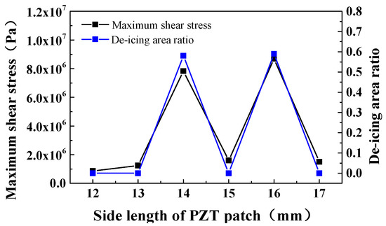
Figure 9.
Variations in the maximum shear stress and the deicing area ratio with side length of the PZT patch.
As shown in Figure 9, when the side length of the PZT patch is 16 mm × 16 mm, and the vibration frequency is 87 kHz, the deicing area ratio is highest, and the value is 0.59. When the side length of the PZT patch is 14 mm × 14 mm, and the vibration frequency is 79 kHz, the deicing area ratio is 0.58. The areas are approximately equal under these two conditions. In contrast, when the side length of the PZT patch is 16 mm × 16 mm, and the excitation frequency is 59 kHz, the deicing area ratio is very small, and its value is 0.074. These results show that there is an optimum side length for the PZT patch, as the size of an iced plate is constant. In this case, the deicing area ratio is highest, and the ultrasonic vibration deicing affecting the reduction in the adhesive force of ice is significant.
The reason for this result is that when the side length of the PZT patch is short, the output power of the PZT patch is low, and the bending deformation of the iced aluminum alloy plate excited by the PZT patch is small. Then, the shear stress and deicing area ratio are both low. When the side length of the PZT patch is long, although the output power of the PZT patch is high, the composite stiffness of an iced plate with PZT patch also increases along with the size of the PZT patch, which results in a reduction in the bending deformation of the iced plate. Then, the shear stress at the adhesive interface decreases. Therefore, an appropriate side length of the PZT patch should be decided for designing an ultrasonic deicing system in order to improve the deicing effect.
3.2. The Effect of Thickness
To investigate the effect of the thickness of the PZT patch on the shear stress at the adhesive interface, the variations in maximum shear stress and deicing area ratio P were calculated by harmonic response analysis. The model size of the iced aluminum alloy plate was 60 mm × 60 mm × 2 mm, and the thickness of the ice was 2 mm. Based on the simulation results in Section 3.1, the PZT patch with a side length of 16 mm was selected as the research object, and the thickness was in the range of 1~3 mm. The driving voltage Vp-p (peak to peak) was 400 V. The waveform of driving voltage was sinusoidal. The calculation results are shown in Figure 10.
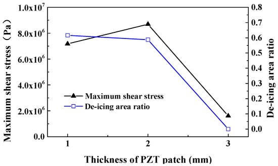
Figure 10.
Maximum shear stress and the deicing area ratio changing with the thickness of the PZT patch.
As shown in Figure 10, when the thickness of the PZT patch is 1 mm, the maximum shear stress and the deicing area ratio are both high, which are 7.17 × 10⁶ Pa and 0.62, respectively. The cloud image of the distributions of shear stress is shown in Figure 11.
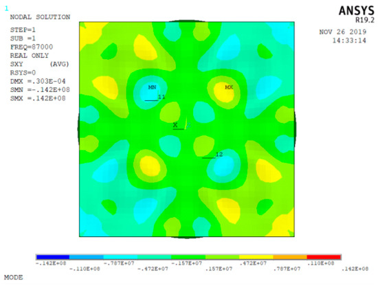
Figure 11.
Cloud image of the distributions of shear stress at the adhesive interface (the thickness of the PZT patch is 1 mm).
As shown in Figure 11, the higher deicing shear stresses mainly concentrate in the four corners of the iced aluminum alloy plate. This distribution characteristic can also reduce the adhesive strength of the ice near the corners. In contrast, according to Figure 8b and Figure 10, as the thickness of the PZT patch is 2 mm, the deicing area ratio is slightly lower. However, the maximum shear stress is highest. They are 0.59 and 8.69 × 10⁶ Pa, respectively. In these two cases, the deicing effects are similar. As the thickness of the PZT patch continues to increase, the maximum shear stress and the deicing area ratio both decrease. Therefore, as the sizes of the iced aluminum alloy plate and the PZT patch are constant, and the thickness of the PZT patch is thin, the shear stress and the deicing area ratio are both high.
The reason for the reductions in shear stress and the deicing area ratio is that, as the PZT patch is too thick, it leads to an increase in the stiffness of the iced aluminum alloy plate. Then, the bending deformation of the iced aluminum alloy plate caused by the inverse piezoelectric effect decreases, and the shear stress at the adhesive interface also decreases.
4. Experiment on the Adhesive Force of Ice
4.1. Experimental Scheme
In this paper, for quantitatively analyzing the variation in adhesive strength of ice under ultrasonic vibration, a torque acting on the ice layer was selected as an external load. Under the action of external torque, the shear force is generated at the adhesive interface between ice and aluminum alloy plate. In this method, the variation in adhesive strength of the ice, which results from ultrasonic vibration, can be estimated by a change in external torque.
In the experiment, an aluminum alloy plate was manufactured whose material number is 7075. The material parameters of the aluminum alloy 7075, including density, elastic modulus, and Poisson ratio, are 2.7 × 10³ kg/m3, 70 GPa, and 0.3, respectively, which are provided by a mechanical factory. The size of the aluminum alloy plate is 60 mm × 60 mm × 2 mm. The size of the ice sample is also 60 mm × 60 mm × 2 mm, which was frozen with the aluminum alloy plate together in the condition of −18 °C. Two sizes of PZT patches whose model were PZT-4 were selected according to the simulation results, which are 14 mm × 14 mm × 2 mm and 16 mm × 16 mm × 2 mm, respectively. The PZT patch was adhered to the aluminum alloy plate by an epoxy resin adhesive named Araldite. This kind of adhesive has better conductivity. Based on the theoretical calculation results in Table 2, the excitation frequencies in the experiment and the experimental scheme are listed in Table 3.
Table 3.
Experimental scheme.
4.2. Experimental System
To quantitatively analyze the effect of ultrasonic vibration on the adhesive force of ice, an experimental system for measuring the adhesive torque of ice was designed and built in this paper. The experimental system is shown in Figure 12.
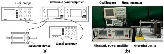
Figure 12.
Experimental system: (a) sketch map of the experimental system; (b) image of the experimental system.
As shown in Figure 12, the experimental system comprised a signal generator, an ultrasonic power amplifier, a device for measuring the adhesive torque of ice, etc. The signal generator, whose model is RIGOL DG1022Z, was used to generate a sinusoidal signal that can be continually modulated. The ultrasonic power amplifier, whose model is LONG YI DGR-3001, was used to amplify the power of the sinusoidal signal from the signal generator and drive the PZT patch to alternatively extend and contract. Then, the iced aluminum alloy plate vibrated with the PZT patch in high frequency.
For obtaining the adhesive torsional force (adhesive torque) of ice, a self-developed experimental device was designed and manufactured, which is shown in Figure 13. In the process of measurement, the device was placed in a refrigerator all the time, and the temperature of the substrate (aluminum alloy plate) was about −18 °C.
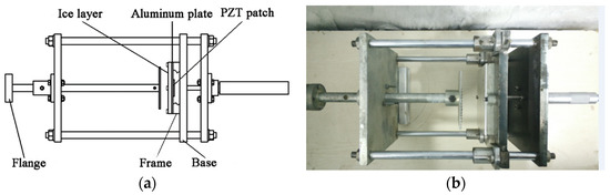
Figure 13.
Measuring device for the adhesive torque of ice: (a) sketch map of the measuring device; (b) prototype of the measuring device.
As shown in Figure 13a, the device mainly comprised a fixed part and a torque application part. The fixed part was used to fix a sample of an iced aluminum alloy plate, and the torque application part was used to apply torque to ice. From Figure 13a, the sample of an iced aluminum alloy plate was fixed on the frame, which was bolted on the base. The frame had a hollow structure; the PZT patch, adhered on the opposite side of the iced aluminum alloy plate, was located in this space. One end of a flange was used to apply torque, and the opposite end was frozen with the iced aluminum alloy plate together before each measurement. In this way, the torque could be applied to the ice layer, and the adhesive torque of ice could be measured.
4.3. Experimental Results and Analysis
To comparatively analyze the experimental results with theoretical ones, the adhesive shear stress of ice, which is its shear force in unit area, must be calculated. Therefore, based on the measuring adhesive torque, an analytical model for calculating the adhesive torsional shear stress of ice was established. The principle of modeling is shown in Figure 14.
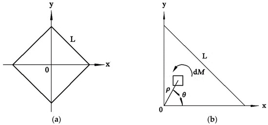
Figure 14.
Principle of the analytical model: (a) position of the icing sample in the Cartesian coordinates; (b) a quarter of the icing sample.
As shown in Figure 14a, because the shape of the iced aluminum alloy is square, for simplifying the process of modeling, the diagonals of the iced aluminum alloy plate coincide with the X-axis (abscissa) and the Y-axis (ordinate) of the Cartesian coordinates, respectively. Considering the axial symmetry of the square shape along the diagonals, one-fourth of it was selected as the modeling object, which is shown in Figure 14b. For simplifying the processes of modeling and calculation, the equation of infinitesimal adhesive torque dM is expressed in the form of the polar coordinate system, which is expressed as Equation (5).
where dM is the infinitesimal adhesive torque of the ice; τa is the adhesive torsional shear stress of the ice; ρ is the polar radius of the infinitesimal ice; θ is the polar angle of the infinitesimal ice.
According to the range of the polar angle and the polar radius in Figure 13b, the adhesive torque M of the whole ice covering on an aluminum alloy plate surface can be calculated by Equation (5), which is expressed as Equation (6).
where M is the adhesive torque of ice covering on the whole aluminum alloy plate surface; L is the side length of the iced aluminum alloy plate.
According to Equation (6), the adhesive torsional shear stress of ice is calculated as Equation (7).
For calculating the adhesive torsional shear stress τa, the torque M in Equation (7) is substituted by the adhesive torque measured in the experiment, and the calculation results under different excitation frequencies are shown in Figure 15.
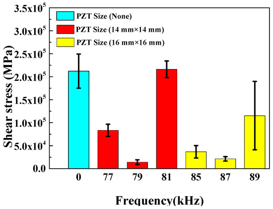
Figure 15.
Adhesive torsional shear stresses of ice under the different frequencies.
As shown in Figure 15, when the iced aluminum alloy plate is not excited by ultrasonic vibration, the adhesive torsional shear stress of ice is about 0.21 MPa. In contrast, when the size of the PZT patch is 14 mm × 14 mm × 2 mm, and the vibration frequency is 79 kHz, the adhesive torsional shear stress of ice is lowest, which is about 0.014 MPa. It is only approximately 7% of that without ultrasonic vibration. When the vibration frequency is 81 kHz, the adhesive torsional shear stress is approximate to the one without ultrasonic vibration. In this case, the ultrasonic vibration does not have a deicing effect. The experimental results show that high shear stresses exist at the adhesive interface when the vibration frequency is 79 kHz, which leads to a decrease in the adhesive force of ice. On the contrary, the shear stress is small when the vibration frequency is 81 kHz. These experimental results agree with the theoretical analysis results listed in Table 2.
In addition, when the size of the PZT patch is 16 mm×16 mm×2 mm, and the excitation frequencies are 85 kHz and 87 kHz, the adhesive torsional shear stresses of ice are also low. They are 0.037 MPa and 0.021 MPa, respectively. From Figure 15, it can be derived that the adhesive torsional shear stresses are lower than those of the iced aluminum alloy plate with a PZT size of 14 mm × 14 mm × 2 mm in general. The reason for this result is that when the size of the PZT patch is 16 mm × 16 mm × 2 mm, the excitation frequency and output power of piezoelectric ceramics are higher in unit time. The bending deformation and shear stress at the adhesive interface are higher in each excitation frequency condition, and the maximum shear stress is higher, as listed in Table 2, which leads to smaller adhesive shear stress of ice.
5. Conclusions
In this paper, the effect of ultrasonic vibration on the adhesive characteristic of ice, covering the whole aluminum alloy plate surface, was researched by simulation and experiment. Some conclusions are summarized and listed as follows:
1. The effects of excitation frequency and the side length of the PZT patch on the maximum shear stresses at the adhesive interface between ice and aluminum alloy plate were investigated by harmonic simulations. The results reveal that there is an optimum side length of the PZT patch for a constant size of plate substrate. In this case, the shear stress is largest at the adhesive interface, and the deicing area ratio is high. For an aluminum alloy plate with a size of 60 mm × 60 mm × 2 mm, when the side lengths of the PZT patches are 14 mm and 16 mm, the maximum shear stress and deicing area ratio are both high.
2. The effects of the thickness of the PZT patch on maximum shear stresses at the adhesive interface and the deicing area ratio were explored by simulations. When the thickness of the PZT patch is thin, the maximum shear stress and the deicing area ratio are both high. With the increase in the thickness of the PZT patch, both of them decrease dramatically.
3. An experimental system for measuring the adhesive torque of ice was designed and set up, and an analytical model for calculating the adhesive torsional shear stress of ice was established. Based on the measuring system and analytical model, the adhesive torque and torsional shear stresses of ice under the different excitation frequencies were measured and calculated. When the excitation frequency is 79 kHz, the adhesive torsional shear stress of ice is 0.014 MPa, only 7% of the one without ultrasonic vibration. When the side length of the PZT patch is 16 mm, the adhesive torsional shear stresses under the different frequencies are lower than those in the PZT patch with a side length of 14 mm in general.
To summarize, in the present study, although the ultrasonic microvibration did not fully remove the ice from the aluminum alloy plate surface, it dramatically decreased the adhesive strength of ice. This indicates that the ultrasonic vibration has a deicing effect and reduces the difficulty in deicing. Meanwhile, these research findings lay theoretical and experimental foundations for exploring the ultrasonic deicing method in depth in future studies.
Author Contributions
Conceptualization, Y.L. and W.G.; methodology, Y.L.; software, H.S. and W.G.; validation, H.S.; formal analysis, H.S. and W.G. investigation, H.S., Y.L. and W.G.; resources, Y.L. and W.G.; data curation, H.S.; writing—original draft preparation, H.S.; writing—review and editing, Y.L. and W.G.; visualization, H.S.; supervision, Y.L. and W.G.; project administration, Y.L. and W.G.; funding acquisition, Y.L. and W.G. All authors have read and agreed to the published version of the manuscript.
Funding
This research is supported by the Key Laboratory of Wind Energy and Solar Energy Technology Open Fund (Inner Mongolia University of Technology), Ministry of Education, grant number 2020ZD03; the National Natural Science Foundation of China (NSFC), grant number 51976029.
Institutional Review Board Statement
Not applicable.
Informed Consent Statement
Not applicable.
Conflicts of Interest
The authors declare no conflict of interest.
References
- Dalili, N.; Edrisy, A.; Carriveau, R. A review of surface engineering issues critical to wind turbine performance. Renew. Energy 2009, 13, 428–438. [Google Scholar] [CrossRef]
- Bose, N. Icing on a small horizontal axis wind turbine part 1: Glaze ice profile. J. Wind Eng. Ind. Aerodyn. 1992, 45, 75–85. [Google Scholar] [CrossRef]
- Malhotra, S. Design considerations for offshore wind turbine foundations in the United States. In Proceedings of the International Offshore and Polar Engineering Conference, Osaka, Japan, 21–26 July 2009. [Google Scholar]
- Pan, J.; Loth, E.; Bragg, M. RANS simulations of airfoils with ice shapes. In Proceedings of the 41st Aerospace Sciences Meeting and Exhibit AIAA, Reno, NV, USA, 6–9 January 2003. [Google Scholar]
- Gent, R.W.; Dart, N.P.; Cansdale, J.T. Aircraft icing. Philos. Trans. R. Soc. A Math. Phys. Eng. Sci. 2000, 358, 2873–2911. [Google Scholar] [CrossRef]
- Li, Y.; Sun, C.; Jiang, Y. Scaling method of the rotating blade of a wind turbine for a rime ice wind tunnel test. Energies 2019, 12, 627. [Google Scholar] [CrossRef] [Green Version]
- Guo, W.F.; Shen, H.; Li, Y. Wind tunnel tests of the rime icing characteristics of a straight-bladed vertical axis wind turbine. Renew. Energy 2021, 179, 116–132. [Google Scholar] [CrossRef]
- Guo, W.F.; Zhang, Y.W.; Li, Y. A Wind Tunnel Experimental Study on the Icing Characteristics of a Cylinder Rotating around a Vertical Axis. Appl. Sci. 2021, 11, 10383. [Google Scholar] [CrossRef]
- Cao, Y.; Huang, J.; Yin, J. Numerical simulation of three-dimensional ice accretion on an aircraft wing. Int. J. Heat Mass Transf. 2016, 92, 34–54. [Google Scholar] [CrossRef]
- Cao, Y.; Hou, S. Extension to the Myers Model for Calculation of Three-Dimensional Glaze Icing. J. Aircr. 2015, 8, 106–116. [Google Scholar] [CrossRef]
- Thomas, S.K.; Cassoni, R.P.; Macarthur, C.D. Aircraft anti-icing and de-icing techniques and modeling. J. Aircr. 1996, 33, 841–854. [Google Scholar] [CrossRef]
- Martin, C.A.; Putt, J.C. Advanced pneumatic impulse ice protection system (PIIP) for aircraft. J. Aircr. 1992, 29, 714–716. [Google Scholar] [CrossRef]
- Palacios, J.L.; Smith, E.C.; Gao, H. Ultrasonic shear wave anti-Icing system for helicopter rotor blades. In Proceedings of the American Helicopter Society 62nd Annual Forum, Phoenix, AZ, USA, 9–11 May 2006. [Google Scholar]
- Kulinich, S.A.; Farzaneh, M. Ice adhesion on super-hydrophobic surfaces. Appl. Surf. Sci. 2009, 255, 8153–8157. [Google Scholar] [CrossRef]
- Habibi, H.; Cheng, L.; Zheng, H. A dual de-icing system for wind turbine blades combining high-power ultrasonic guided waves and low-frequency forced vibrations. Renew. Energy 2015, 83, 859–870. [Google Scholar] [CrossRef] [Green Version]
- Zhu, Y.; Palacios, J.; Rose, J. De-icing of multi-layer composite plates using ultrasonic guided waves. In Proceedings of the 49th AIAA/ASME/ASCE/AHS/ASC Structures, Structural Dynamics and Materials Conference, Schaumburg, IL, USA, 7–10 April 2008. [Google Scholar]
- Palacios, J.; Smith, E.; Rose, J. Ultrasonic de-icing of wind-tunnel impact icing. J. Aircr. 2011, 48, 1020–1027. [Google Scholar] [CrossRef]
- Palacios, J.; Smith, E.; Rose, J. Instantaneous de-icing of freezer ice via ultrasonic actuation. AIAA J. 2011, 49, 1158–1167. [Google Scholar] [CrossRef] [Green Version]
- Zeng, J.; Song, B. Research on experiment and numerical simulation of ultrasonic de-icing for wind turbine blades. Renew. Energy 2017, 113, 706–712. [Google Scholar] [CrossRef]
- Tan, H.; Xu, G.; Tao, T. Investigation on the ultrasonic propagation mechanism and its application on air-source heat pump defrosting. Appl. Therm. Eng. 2016, 107, 479–492. [Google Scholar] [CrossRef]
- Guo, W.F.; Li, Y.; Wang, S.L. Experimental researches on anti-icing of plate in icing wind tunnel condition based on ultrasonic vibration. China Sci. Pap. 2017, 12, 560–563. (In Chinese) [Google Scholar]
- Chu, M.C.; Scavuzzo, R.J. Adhesive shear strength of impact ice. AIAA J. 1991, 29, 1921–1926. [Google Scholar] [CrossRef]
- Jellinek, H. Adhesive properties of ice. J. Colloid Sci. 1959, 14, 268–280. [Google Scholar] [CrossRef]
- Scavuzzo, R.J.; Chu, M.L.; Kellackey, C.J. Impact ice stresses in rotating airfoils. J. Aircr. 2015, 28, 450–455. [Google Scholar] [CrossRef]
- Wu, G. Aluminum alloy material property. In Aluminum and Aluminum Alloy Material Handbook, 1st ed.; Wu, G., Yao, L.J., Eds.; Science Press: Beijing, China, 1994; Volume 1, pp. 118–268. [Google Scholar]
- Guo, Y.K.; Meng, W.Y. Experimental Investigations on Mechanical Properties of Ice. J. North China Univ. Water Resour. Electr. Power Nat. Sci. Ed. 2015, 36, 40–43. (In Chinese) [Google Scholar]
- Luan, G.D. Piezoelectric material. In Piezoelectric Transducers and Arrays, 1st ed.; Luan, G.D., Zhang, J.D., Eds.; Peking University Press: Beijing, China, 2005; Volume 1, pp. 93–95. [Google Scholar]
Publisher’s Note: MDPI stays neutral with regard to jurisdictional claims in published maps and institutional affiliations. |
© 2022 by the authors. Licensee MDPI, Basel, Switzerland. This article is an open access article distributed under the terms and conditions of the Creative Commons Attribution (CC BY) license (https://creativecommons.org/licenses/by/4.0/).