Article

Progressive Collapse of the Base-Isolated Frame Structures Supported by Stepped Foundation in Mountainous City

1
Key Lab of Education Ministry for Construction and New Technology of Mountain Cities, Chongqing University, Chongqing 400045, China
2
College of Civil Engineering, Chongqing University, Chongqing 400045, China
*
Author to whom correspondence should be addressed.
Appl. Sci. 2022, 12(4), 2151; https://doi.org/10.3390/app12042151
Submission received: 16 December 2021 / Revised: 8 February 2022 / Accepted: 14 February 2022 / Published: 18 February 2022

Abstract

:
Base-isolated frames supported by stepped foundation in mountainous areas possess their own particularity, so its progressive collapse dynamic response performance and dynamic effect propagation path are very different from those of ordinary flat ground-isolated structural systems. In order to study the progressive collapse performance of the base-isolated frames supported by stepped foundation in mountainous areas under two-directional coupled dynamic excitation, a four-span three-story plane frame demolition column test was simulated to verify the reliability of the computing platform. The common ground motion and three types of long-period ground motions were selected, and the two-dimensional dynamic coupling of the ordinary flat ground isolation structure and the base-isolated frames supported by stepped foundation in mountainous areas was obtained based on the demolition method. First, the seismic isolation structure was subjected to the collapse dynamic response under the vertical unbalanced load, then the collapse dynamic response under the vertical unbalanced load and the horizontal seismic coupling excitation was made; the two were compared and analyzed. It can be used as a reference for the design of progressive collapse of the frame structure of the base-isolated frames supported by stepped foundation in mountainous areas.

1. Introduction

Frames supported by stepped foundation is a common structural form in the construction of mountainous cities. It refers to a structural system in which there are two fixed ends in the same unit that are not in the same plane, and the floor is set according to the height below the highest ground point. As shown in Figure 1, as the lateral stiffness of the lower grounded floor was significantly lower than that of the upper grounded floor, there was obvious vertical irregularity in the drop-off frame structure. Therefore, the dynamic response characteristics and the transmission path of dynamic effects of progressive collapse were quite different from that of ordinary flat-ground isolation structure systems.
After the M7.0 earthquake in Ya’an, Sichuan Province, China on 20 April 2013, people’s attention has been drawn to the Lushan People’s Hospital built with seismic isolation technology because of its complete appearance and small damage. Seismic isolation structures have been widely used in lifeline engineering and important buildings in seismic areas due to their good performance in earthquakes. Structural collapse accidents are often accompanied by severe loss of life and property and adverse social impact. Since the events of “Ronan point apartment collapse in UK” and “9.11”, scholars at home and abroad have carried out a lot of research on the progressive collapse of structures. Progressive collapse [1] refers to local destruction of the structure, which leads to a chain reaction leading to the destruction of adjacent members, resulting in extensive destruction or overall collapse that is disproportionate to the initial failure.
Marjanishvili et al. [2] studied the progressive collapse method; Tsai et al. [3] studied and analyzed dynamic response characteristics in the process of structural collapse. Kim Jinkoo’s research evaluated the progressive collapse resistance of steel frames [4]. Qian Jiiruet al. [5] studied the progressive collapse mechanism of reinforced concrete frame structures. Lyu Xilin et al. [6] established a base-isolated high-rise structure model, and applied ordinary ground motion and long-period ground motion with equal peak ground acceleration (PGA) to it, indicating that the seismic performance index of isolated structure under long-period ground motion is weak. Lu Xinzheng et al. [7,8] studied the influence of beam and column with different design parameters on the beam mechanism and catenary mechanism of structural progressive collapse and proposed a new analytical calculation model for the action of compressive arch of reinforced concrete structures in the follow-up study. Ren Peiqi et al. [9] found that many experimental studies focused on beam-column or continuous beam structures but neglected the influence of plates. Then, they studied the progressive collapse resistance mechanism of reinforced concrete (RC) floor systems by changing the design parameters of the slabs. Ariga et al. [10] studied base-isolated buildings with friction-type isolation bearings; the results showed that the friction-type bearings could weaken the resonance effect caused by long-period ground motion.
Generally speaking, the problem of progressive collapse resistance of structures focuses on the accidental failure of a member of the structure, the dynamic response and structural damage propagation of the remaining structures under unbalanced loads. Xie Fuzhe et al. [11] studied the progressive collapse resistance of frame structures considering surrounding constraints; Pan Yi et al. [12] studied the anti-progressive collapse mechanism and dynamic response of prefabricated structures. The preliminary exploration of the progressive collapse of the base isolated structure shows that [13] the vertical load borne by the adjacent isolated support will increase sharply and instantaneously after the individual support of the isolated structure is damaged and out of work due to accidental action. Even if the transient balance can be maintained under the vertical load, a slight horizontal excitation, such as an earthquake or wind vibration, may induce the isolated supports to collapse one after another.
Presently, China’s urbanization construction is developing rapidly, the supply of land resources for construction is tight, and the application of mountain building structure is increasing. The irregularity of the frames supported by stepped foundation in mountainous areas often leads to problems such as continuity variation, redundancy reduction, and complexity of the transmission path, which are significantly different from common regular frame structures. This also makes the existing research results on the collapse of the common rule frame structure not fully applicable, so it is necessary to study the progressive collapse resistance performance of the frames supported by stepped foundation in mountainous areas. At present, the research on progressive collapse mainly focuses on earthquake-resistant mountainous structures, while the dynamic effects of progressive collapse of seismically isolated mountainous structures are less studied. The lateral stiffness of the isolation layer of the seismic isolation structure is weak; the alternative load transfer path and the remaining structure system exist in different ways from the non-seismic isolation structure under unexpected disaster loads such as impact, fire and foundation collapse. Therefore, compared with traditional seismic structures, the dynamic response characteristics and the transmission path of dynamic effects of progressive collapse of seismic isolation structures need to be studied.
Based on the fact that China’s earthquake disasters are frequent and that the inherent vertical rigidity of mountainous building structures is irregular, resulting in poor seismic performance [14], seismic isolation technology is constantly being developed and applied to mountainous buildings. Mountain isolation structures themselves possess their own particularity, so their failure mode and mechanical performance are very different from ordinary flat isolation structure systems [15]. After the individual support of the seismic isolation structure exits work due to accidental damage, the vertical load on the adjacent seismic isolation support will increase instantaneously. Even if the transient balance can be maintained under the action of vertical load, a slight horizontal excitation, such as an earthquake or wind vibration, may induce successive instability and collapse of the seismic isolation support. If the damage of the bearing is not identified in time, some of the bearings lose their vertical bearing capacity and the structure is subjected to earthquake action at this time. In this way, the vertical unbalanced load is coupled with the horizontal seismic action, causing the seismic isolation structure to appear disproportionate to the initial damage or collapse and spread, which is very dangerous for seismic isolation structures. Therefore, this paper conducted research on the collapse resistance performance of the bottom column (seismic bearing) of the base isolation mountain falling layer frame under the bidirectional dynamic coupling excitation after the accidental failure and provides a reference for the design of mountainous isolation buildings.

2. Numerical Model and Experimental Verification

2.1. Fiber Element Model

Reinforced concrete is composed of two kinds of materials, concrete and steel bars. The nonlinearity of materials will greatly affect the performance of reinforced concrete. Therefore, the appropriate material constitutive model, hysteretic energy dissipation and element model must be selected for nonlinear dynamic analysis of structures.
The finite element stiffness method is generally used to solve the elastoplastic problem; it is accurate and efficient. The displacement shape function used by the fiber beam-column element is a typical Hermite cubic interpolation function. The flexibility method is based on the force function corresponding to the stiffness method. When the material possesses a nonlinear curvature distribution, the flexibility method can accurately simulate the mechanical properties and material properties of reinforced concrete members. The fiber element model in the LSDYNA software used in this paper is based on the finite element flexibility method.
The basic assumptions of LSDYNA [16] fiber element: (1) based on geometric linear small deformation; (2) satisfying the assumption of flat section; (Based on the assumption of flat section, the fiber model divides the member into many fiber bundles in the direction of cross section. Each fiber is uniaxial stressed. According to the assumption of flat section and the stress–strain relationship, the strain of each fiber can be obtained. The unit stiffness matrix is formed by iteration calculation within the unit); (3) the beam unit is divided into multiple finite element sections. Each section maintains the assumption of flat section and maintains a consistent constitutive relationship; (4) shear slip and bond slip are not considered; (5) torque, bending moment, and shear are not coupled with each other.

2.2. Numerical Model and Parameter Setting

In order to verify the accuracy of the LS-DYNA program, a test on the progressive collapse of reinforced concrete frame structures in Document 17 was numerically simulated [17]. The test device and instrument layout are shown in Figure 2 and Figure 3.
The column was discretized into 10 beam elements along the axial direction; the length of each element was less than the length of the plastic hinge of the column foot; the beam was divided into three sections of reinforcement along the axial direction (the middle span, the left support bearing, and the right support bearing); each section of the beam was discretely divided into 4 elements; the length of each element was 0.5 m. The columns and beams were separated into 100 concrete fibers along the cross section; the steel bars were separated into 4 or 8 fibers. The schematic diagram of the cross-section of the beam and column is shown in Figure 4 (the marked part is reinforced fiber).
This paper uses LS-DYNA as the solver to solve the finite element model; the finite element model uses MAT-174 material to simulate reinforced concrete. The material model can simulate plain concrete and steel reinforcement materials by setting the reinforcement ratio (FRACR = 0, representing plain concrete; FRACR = 1, representing steel reinforcement). The reinforcement adopts a uniaxial elastoplastic flow strengthening constitutive model, and the yield stress and elastic modulus were measured using actual values. The Ramberg–Osgood equation [18] is used to simulate the stiffness degradation of the material under repeated loading [19]. In the monotonic compression stage, the Park and Kent methods described by Park and Paulay were used [20]; the material follows a parabolic stress–strain curve. In the stretching stage, the stress increased linearly with the strain until the stretching limit was reached. Thereafter, the stiffness and strength decayed as the strain increased. When the frame model was established, stirrups were not set, but the effect of stirrups was realized by considering the reinforcement of confined concrete. Core concrete adopted the Kent–Park constitutive model [21]. The axial compressive strength and elastic modulus of concrete were measured as standard values. Considering the restraint effect of stirrups on concrete, the constitutive relationship formula of concrete in the core area is as follows:
f c = { K f c [ 2 ε c K ε 0 ( ε c K ε 0 ) 2 ] , ε c K ε 0 K f c [ 1 Z m ( ε c K ε 0 ) ] , ε c > K ε 0
when ε c > K ε 0 , f c > 0.2 K f c .
In the formula, K is the strengthening factor of concrete confined by stirrups, which is defined as follows:
K = 1 + ρ s f y h / f c
.
Zm is the slope of the strain softening section of the constitutive relationship of concrete materials, which is defined as follows:
Z m = 0.5 3 + 0.29 f c 145 f c 1000 + 0.75 ρ s b S h K ε 0
.
In this formula:
f c is the compressive strength of the concrete cylinder; f y h is the yield strength of the stirrup(MPa); ρ s is the hoop ratio of the component; b is the width of the concrete core area(mm); ε 0 is the peak strain of unconstrained concrete; S h is the spacing between stirrups (mm).

2.3. Results Analysis

The numerical simulation adopted the same loading method as the experiment; the curve of axial force and displacement of the bottom center column is shown in Figure 5. Through the comparison of curves, it was found that the simulation results in the elastoplastic stage were in good agreement with the test results; the curves were almost the same; in the plastic hinge stage, the error was very small; after the concrete cracks and fails, the flexural bearing capacity of the beam ends was basically lost, that is, the simulation effect after the suspension cable [22] was in good agreement with the test curve, and the error was very small.

3. Two-Directional Coupled Dynamic Excitation Analysis Process

3.1. Design Information

The definition Cm Kn indicates that the number of layers dropped is m, and the number of span dropped is n (As shown in Figure 6, the number of dropped floors and span of the structure is 2 and 3, so it is named C2K3). In order to study the difference in the progressive collapse resistance of the base isolation flat structure and the base-isolated frames supported by stepped foundation in mountainous areas, this paper designed a common frame structure and a frame supported by stepped foundation. The total number of floors of all structures was 6 floors; the layout was also the same, with five vertical spans and three horizontal spans. We selected the border frame (the shaded part in the figure) as the research object, as shown in Figure 6 and Figure 7.
Using PKPM structural design software, in accordance with the “Code for Seismic Design of Buildings” (GB50011-2010) [23], using a separate design method, a seismic isolation structure model was established; The establishment method of isolation structure is shown in Figure 8; the horizontal damping coefficient β was determined. β is the horizontal damping coefficient, which is the maximum value of shear ratio between layers under isolation and non-isolation of the structure under fortification intensity. β describes the extent to which the seismic action of the structure was reduced by the adoption of isolation structures.
Figure 8. Design steps of isolated structure. The LRB500 seismic isolation bearing was selected, and its design load was 1963 kN. Table 1 shows the parameters of the LRB500 seismic isolation support used in the seismic isolation structure model.
Applsci 12 02151 g008
Table 1. Mechanical properties of LRB500 isolated bearing.
Vertical PerformanceCompression Limit Strength
N/mm2
Datum Pressure
N/mm2
Vertical Stiffness
N/mm2
Tensile Limit Strength
N/mm2
491018021.5
50%
Horizontal performance
Equivalent horizontal stiffness
kN/m
Equivalent damping ratio%Secondary stiffness
kN/m
231233949
100%
Horizontal performance
Equivalent horizontal stiffness
kN/m
Equivalent damping ratio%Stiffness before yielding
kN/m
Stiffness after yielding
kN/m
Yield forcekN
148027.2518779865.4
250%
Horizontal performance
Equivalent horizontal stiffness
kN/m
Equivalent damping ratio%Secondary stiffness
kN/m
90718.4635
The building site category was Class II; the seismic fortification intensity was 8 degrees (0.2 g); the designed seismic group was divided into the second group; the frame seismic level was second. The height of the model in all calculation examples was 3.6 m; the height of the seismic isolation layer was 2.8 m. Among them, the column section size was 500 mm × 500 mm; the beam section size was 300 mm × 500 mm. The concrete strength grades were all C30; the longitudinal force-bearing steel bars of the frame beams and columns were hot rolled ribbed bar (HRB)400, and the stirrups were hot rolled plain bar(HPB)300. The dead load on the floor was 5.5 kN/m2; the live load on the floor was 4.5 kN/m2.

3.2. Two-Directional Coupled Dynamic Excitation Analysis Steps
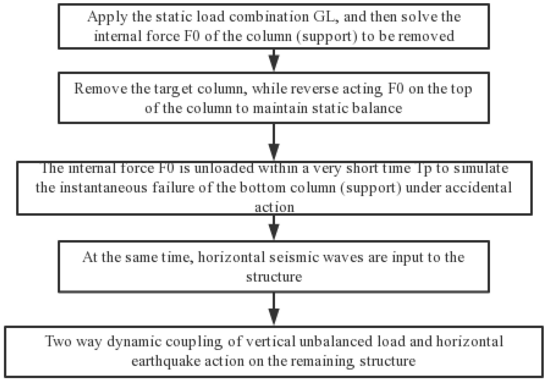
Steps of the method of dismantling the components: firstly, calculate the static force for the intact structure and obtain the internal force of the component; then, dismantle the component and apply its reaction force to the remaining structure to make it in a static equivalent state; finally, the reaction force is removed instantaneously to simulate the instantaneous failure of the component, also known as the alternate load path method. This research method only considers the dynamic effect of the vertical unbalanced load after the component is removed, so this article added the horizontal seismic action, that is, it considered the vertical unbalanced load and the horizontal seismic action at the same time. The analysis process of bidirectional coupling excitation is shown in Figure 9.
The analysis steps are as follows:
(1)
Act on the static load combination GL on the initial structure to solve the internal force F of the column (support bearing) to be dismantled
G L = ( 1.0   D L + 0.25   L L )
where DL is the dead load and LL is the live load.
(2)
Remove the target column (support bearing) from the initial structure and apply the internal force F0 obtained in step (1) to the top of the column in reverse to maintain the static equivalent state.
(3)
Unload the internal force F0 in a very short time t to simulate the instantaneous failure of the support bearing (bottom column) under unexpected action, and input horizontal seismic waves to the structure at the same time, and the remaining structure bears the bidirectional dynamic coupling of the vertical unbalanced load and the horizontal seismic action. The equivalent load is shown in Figure 10.

3.3. Seismic Wave Selection

The “Code for Seismic Design of Buildings” (GB50011-2011) stipulates that, in the time history analysis of the structure, actual strong earthquake records and artificially simulated acceleration time history curves should be selected according to the type of building site and the design earthquake grouping.
The frequency spectrum (frequency spectrum is the response of ground motion of strong earthquake to structures with different natural vibration periods) and duration characteristics of long-period ground motions were very different from those of ordinary ground motions: long-period ground motions possess many spectral components, long-periods, and long durations, while ordinary ground motions possess relatively short periods and are mostly concentrated in the high-hertz spectrum. Due to the existence of the seismic isolation support, the natural vibration period of the base-isolated frames supported by stepped foundation in mountainous areas increases, and the structure can effectively attenuate the effect of ordinary ground motions. However, the seismic damping effect of the seismic isolation structure is not obvious under long-period ground motions. According to the literature [24], three long-period ground motions were selected from the website of the Pacific Earthquake Research Center [25]: they are the near-fault pulsed ground motion TCU110 wave, the far-field anharmonic ground motion TCU110 wave, and the far-field anharmonic ground motion ILA004 wave. The ground motion characteristics are shown in Figure 11. According to the comparison of average acceleration spectrum in Figure 11 (1), it can be seen, intuitively, that the acceleration spectrum of ordinary ground motion TCU052 dropped rapidly after reaching the peak value. However, the decreasing trend of long-period ground motion TCU110 and ILA004 was significantly lower than that of normal ground motion TCU052. The response spectrum of long-period ground motion acceleration is significantly larger than that of normal ground motion after the period is greater than 1 s, and the response spectrum value is still large in the range of 2–3 s of the natural vibration period, especially the second peak acceleration of long-field-like harmonic and long-period ground motion ILA004. It can be seen that long-period ground motion was more likely to cause damage to isolated structures with long-period.

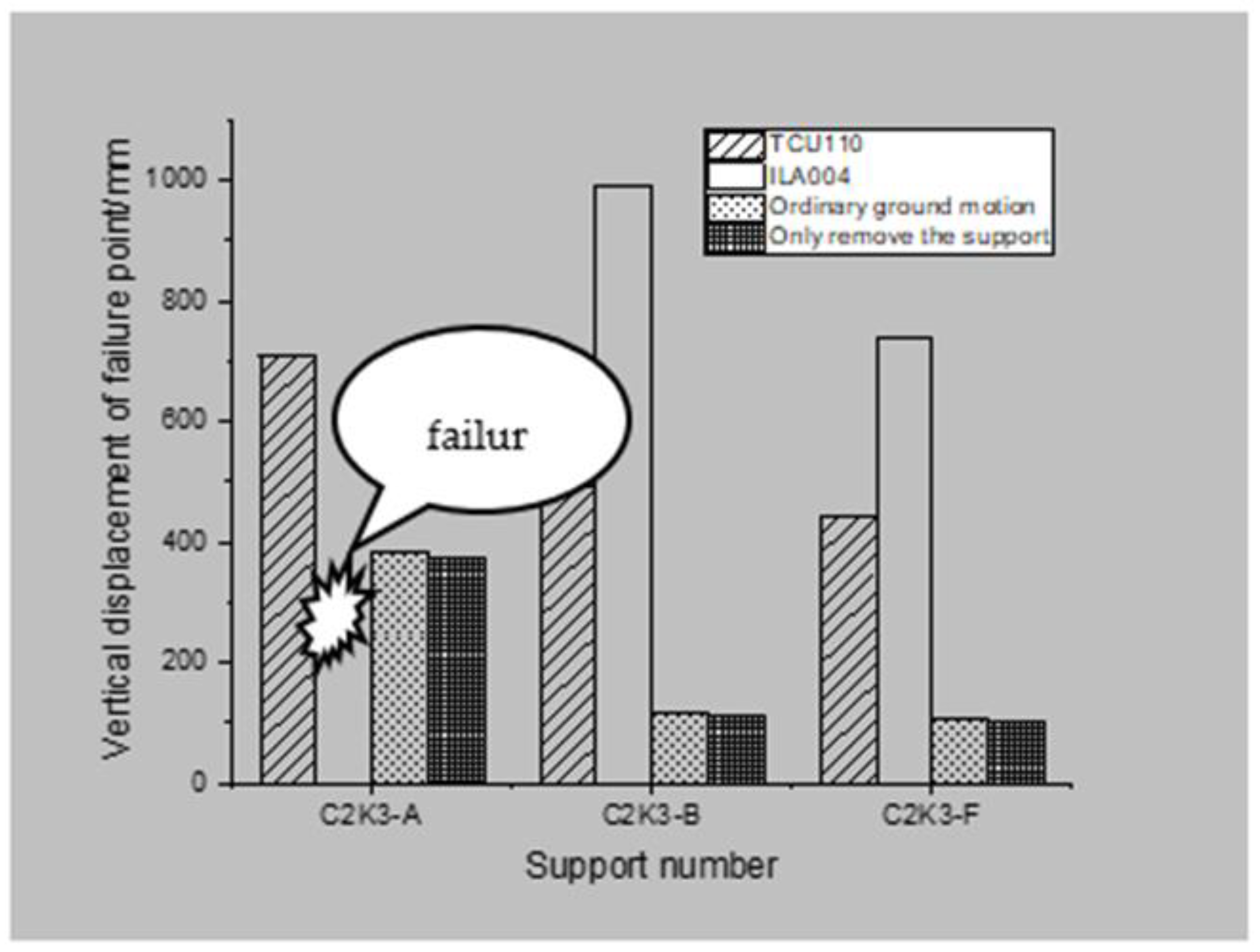
4. Analysis of Structure Progressive Collapse Performance under Ordinary Ground Motion

4.1. Failure Condition of Isolation Bearing

The new version of DoD2010 [16] strictly limits the large deformation beyond the ultimate deformation capacity of the remaining structural system after the components are removed. In this paper, when analyzing the base-isolated frames supported by stepped foundation in mountainous, the collapse failure criterion is adopted: that is, the failure criterion of the remaining structural system after the removal of the vertical members is that the maximum vertical displacement of the failure point is 20% of the connected shortest span.
Take the two-story three-span seismic isolation structure C2K3 to remove the lower ground seismic isolation angle support, A, the lower ground internal seismic isolation support, B, and the upper ground seismic isolation angle support, F, as an example. Analyze the dynamic response of the structure under the condition of vertical unbalanced load and bidirectional dynamic coupling, and the load factors are all taken as 0.5. First, adjust the PGA of the ground motion to 0.7 g, and then remove the support at 1.5 s while inputting the horizontal seismic wave to the X-direction node of the seismic isolation support of the remaining structure. The duration of the seismic wave was 25 s.
It can be seen from Figure 12 that the maximum displacement and stability value of the failure point of the seismic isolation structure only considering the effect of the vertical unbalanced load (only the support is removed) are much smaller than the case under the bidirectional dynamic excitation. Generally speaking, the remaining structure after only dismantling the support is stabilized in 4–5 s, but under the two-way dynamic coupling, the vertical displacement of the failure point of the remaining structure still increases to varying degrees due to the horizontal earthquake. It can be seen from Table 2 that, after the seismic isolation support A was removed, the displacement amplitude and the displacement stability value of the failure point under the bidirectional dynamic excitation were, respectively, higher than 2.8% and 2.2% when only considering the vertical unbalanced load; after the seismic isolation support was removed, the displacement amplitude and stability value of B under bidirectional coupling excitation were 4.3% and 4.4% larger than that without considering the horizontal seismic effect. The same situation increased by 4.7% and 4.9% at point F. The displacement of the failure condition of the inner support B and the upper grounding angle support F was significantly smaller than the failure condition of the corner support A. It can be seen from Table 2 that, for the flat ground isolation structure, after the corner support was removed, the displacement amplitude and the stability value of the failure point under the two-directional coupled dynamic excitation were, respectively, higher than 8.6% and 6.8%, which only consider the vertical unbalance. In the flat ground isolation structure, after the B support is removed, the displacement amplitude and the stability value of the two-directional coupled dynamic excitation are only considered to be 8.4% and 11.7%, respectively, when the vertical unbalance was considered. After the C bearing was removed, the ratio was 9.4% and 11%. In summary, the progressive collapse resistance of the seismic isolation structure under the two-directional coupled dynamic excitation is weaker than that when only the vertical unbalanced load is considered. Comparing Table 1 and Table 2, it can be seen that, under the excitation of two-directional coupled dynamic excitation, the progressive collapse performance of the seismic isolation support of the base-isolated frames supported by stepped foundation in mountainous areas is weaker than that of the flat isolation structure.
In Section 3 of 5.1.2 of the Code for Seismic Design of Buildings GB 50011-2010, two actual strong earthquake records and one artificial simulated acceleration time-history curve should be selected for time-history analysis of structures according to building site category and design earthquake grouping. It can be seen from Figure 13 that when the corner support of the base-isolated frames supported by stepped foundation in mountainous areas fails, the Bm-12 axial force curve fluctuates more and takes longer to stabilize when there is a two- directional coupling with horizontal seismic action. The maximum axial force is 57.8 kN, which is an increase of 21.7% compared with the vertical unbalance. At this time, the structure is at the stage of beam mechanism exertion (that is, the beam end bending moment is mainly used as the main resistance). Since there is no horizontal fixed constraint, the axial force in two-directional coupled dynamic excitation is still under compression. If the load factor is increased, the absolute value of the axial force will continue to increase until the plastic hinge fails under compression and reaches the peak of the beam mechanism bearing capacity. It can be seen from Figure 12b and Figure 13b that the initial axial force of the bearing in the seismic isolation structure C2K3-B was compression, and then it quickly becomes tension and the axial force value increased. At this time, the failure vertical displacement of the vertical unbalance was 108 mm, the failure span beam was in the mechanism conversion stage, and the internal force of the beam presented a tendency of compression to tension. When the vertical unbalanced load factor was 0.56 and the vertical displacement of the failure point was 243 mm, the internal force of the beam was a tension of 11.1 kN, when the load factor under bidirectional coupling was 0.5 and the failure point displacement was 112.8 mm, the failed span beam axial force was already tensile and reached a stable value of 41.2 kN, indicating that the mechanism conversion had been completed under bidirectional dynamic coupling, and the catenary mechanism phase was entered. (That is, through the axial tension as the main resistance.) When considering the two- directional coupling of horizontal seismic action and vertical unbalanced load, the failure span-beam resistance mechanism was earlier than the case of only removing the support, which means that the structure was more prone to progressive collapse.

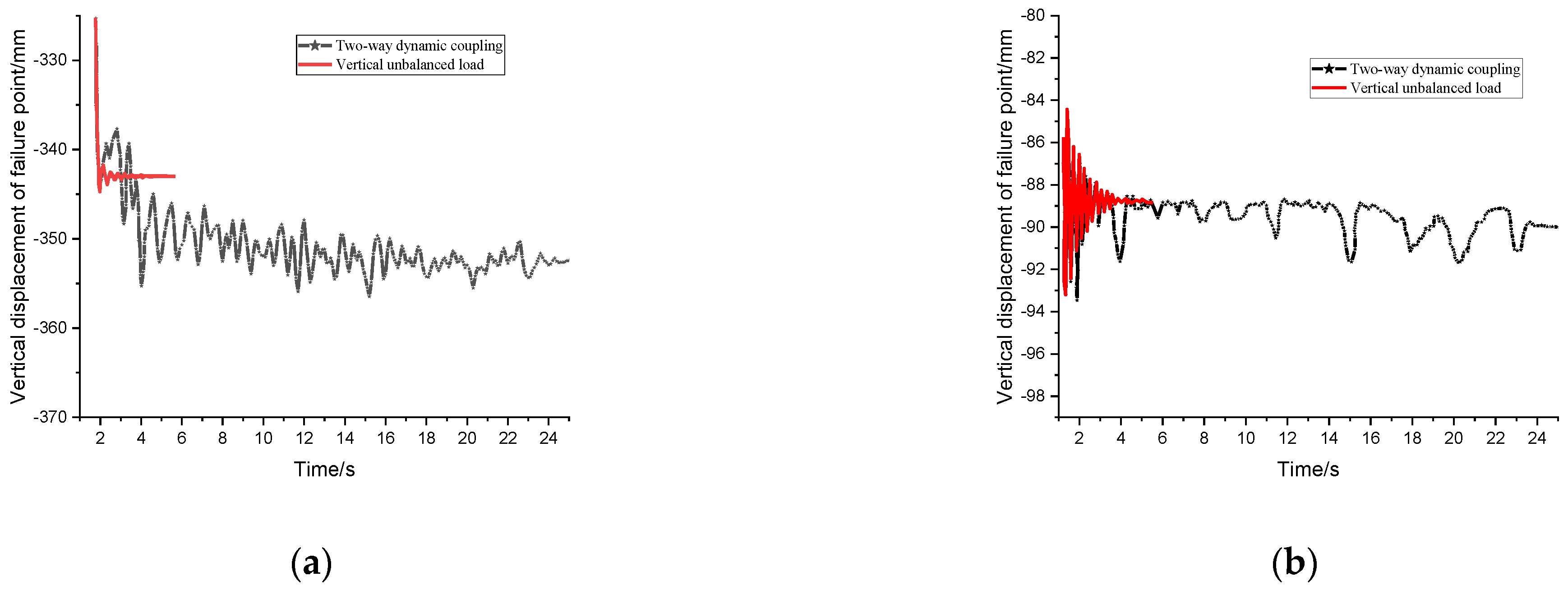
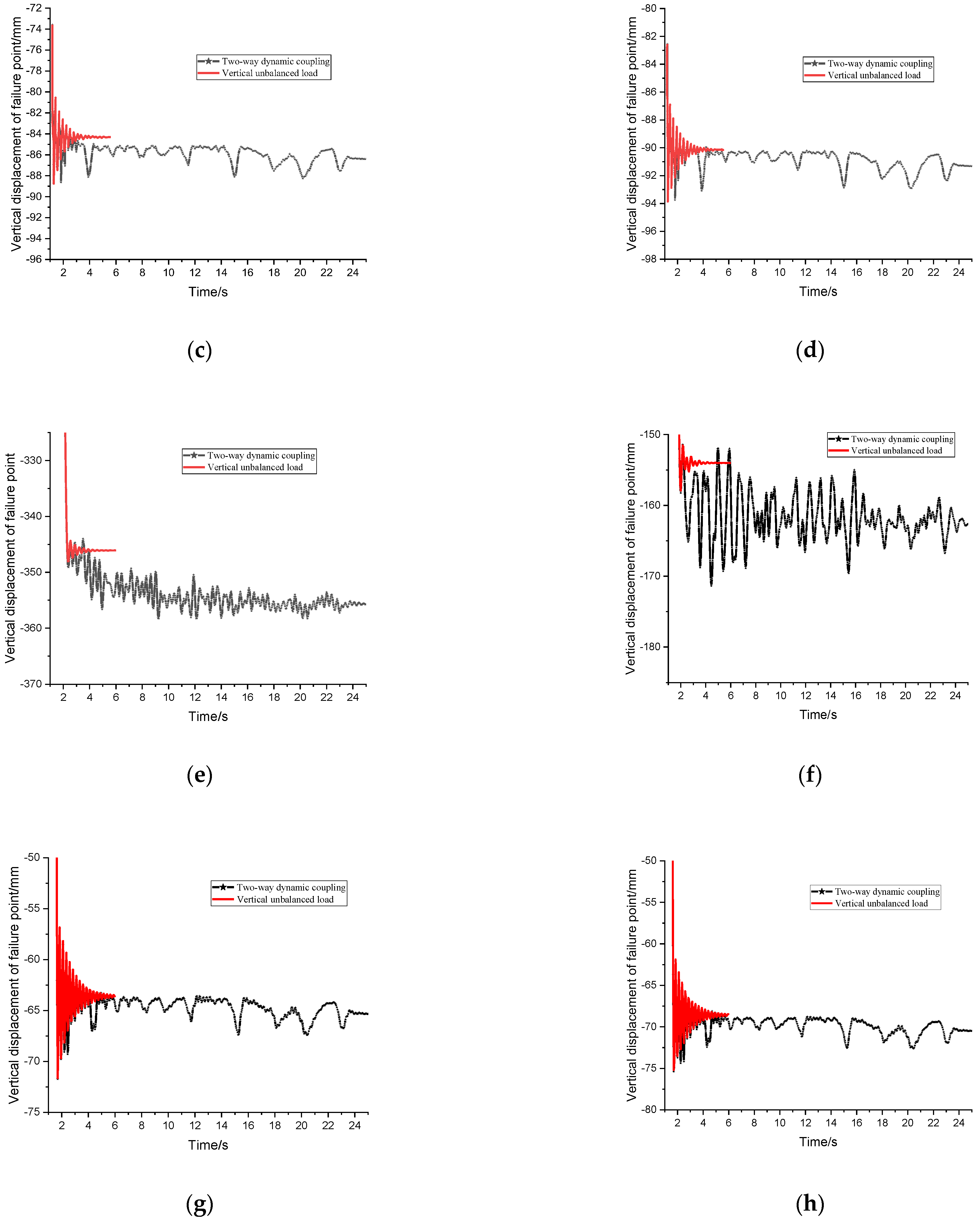
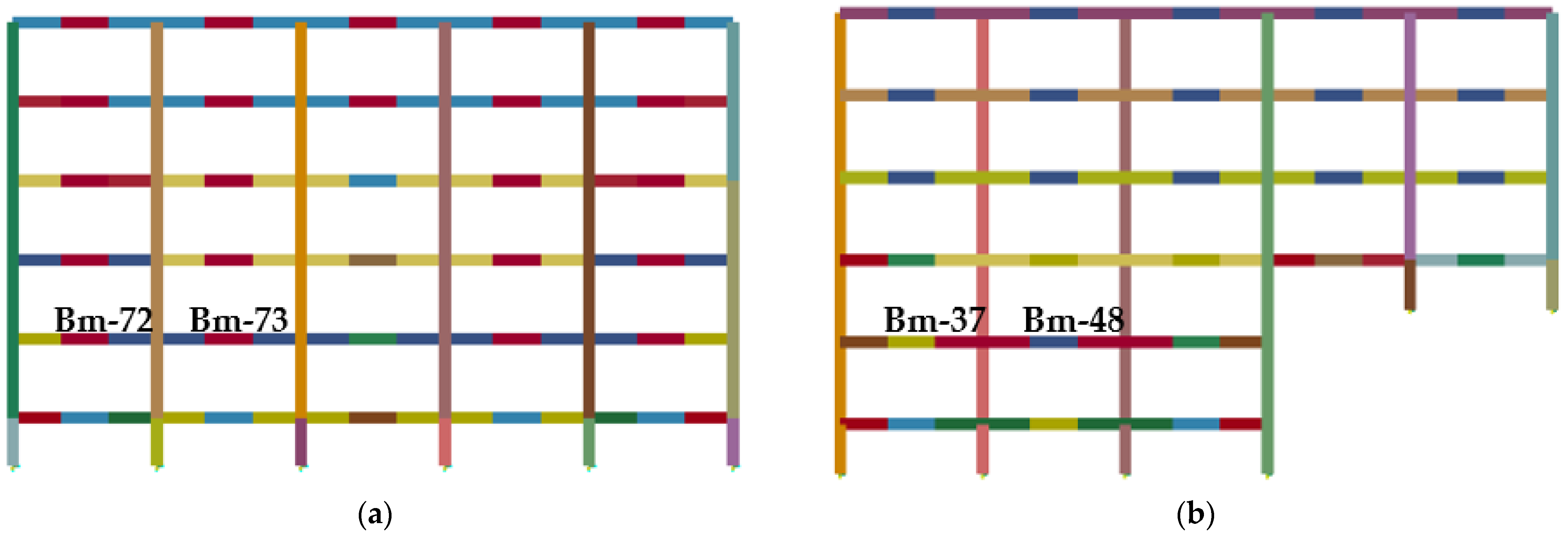
4.2. Failure Condition of Bottom Column

Compared with the traditional seismic structure, because the horizontal stiffness of the isolation layer is much less than the lateral stiffness of the superstructure, the isolation structure shows good performance under an earthquake and possesses better ability to resist horizontal earthquake collapse. Moreover, due to weak horizontal restraint of the isolation bearing of the isolation structure, the catenary mechanism could not be formed, which results in different performance of the progressive collapse of the isolation structure after the failure of the bearing and the failure of the column. The seismic isolation structure C2K3 was used to analyze the dynamic response of the structure under the vertical unbalanced load and two-directional coupled dynamic excitation. To remove the bottom grounding column A, the bottom grounding column B, the bottom of the adjacent column D, the bottom grounding column F, the edge of the adjacent seismic isolation bearing E for analysis, the load coefficient was 0.5. First, we adjusted the PGA of the ground motion to 0.7 g, and then removed the support at 1.5 s while inputting the horizontal seismic wave to the X-direction node of the seismic isolation support of the remaining structure. The duration of the seismic wave was 25 s.
From Figure 14, it can be seen that the maximum displacement and the stability value of the failure point of the seismic isolation structure only considering the vertical unbalanced load effect (that is, only the bottom-layer column is removed) were less than the two-directional coupled dynamic excitation. Generally speaking, the remaining structure was stabilized in 4–5 s under the condition of only removing the bottom column, while the vertical displacement of the failure point of the remaining structure in the two-directional coupled dynamic excitation still increased to varying degrees due to the horizontal earthquake. It can be seen from Table 3 that under the two-directional coupled dynamic excitation, the displacement amplitude and the stability value of the failure point after the removal of the base column A of the seismic isolation structure C3K2 were higher than 3.4% and 2.6%, respectively, without considering the two-directional coupled dynamic excitation; under the two-directional coupled dynamic excitation, the displacement amplitude and stability value of column B of the demolition isolation bottom layer were higher than 1.3% and 1.2% of the cases where only the vertical unbalanced load was considered; for the bottom-layer columns D and E, under the two-directional coupled dynamic excitation, the displacement stability values were higher by 2.5% and 1.3%, respectively, while the displacement amplitudes of the two working conditions of the D and E columns were close; under the two-directional coupled dynamic excitation, the displacement amplitude and stability value of the column F of the C3K2 bottom layer of the seismic isolation structure were higher than 3.0% and 2.8% considering only the vertical unbalanced load; The displacement of the bottom-layer columns B, D, and E failure conditions of the seismic isolation structure C3K2 was significantly smaller than that of the corner columns A and F failure conditions. The displacement values of the corner columns at the bottom of A and F under failure conditions were similar. It can be seen from Table 4 that under the two-directional coupled dynamic excitation, the displacement amplitude and stability value of the failure point were, respectively, higher than the 9.1% and 5.6% of the working condition of only considering the removal of the bottom column after the bottom column A of the flat ground isolation structure was removed; under the two-directional coupled dynamic excitation, the displacement amplitude and stability value of the bottom column B of the flat ground isolation structure after failure were higher than 1.4% and 2.5% when only considering the vertical unbalanced load; under the two-directional coupled dynamic excitation, the displacement amplitude and stability value of the bottom column C of the flat ground isolation structure after failure were higher than 4.4% and 2.9% when only considering the vertical unbalanced load.
It can be seen that, whether it is a flat ground isolation structure or base-isolated frames supported by stepped foundation in mountainous areas, under the two-directional coupled dynamic excitation, the effect on the failure condition of the corner column was greater than that of the inner column. In addition, under the two-directional coupled dynamic excitation, the remaining system of the flat ground isolation structure displayed weaker progressive collapse resistance; after the failure of the bottom-layer column, the progressive collapse resistance of the base-isolated frames supported by stepped foundation in mountainous areas was weaker than that of the flat ground isolation structure. The results showed that: considering the two-directional coupled dynamic excitation, the progressive collapse ability of the base-isolated frames supported by stepped foundation in mountainous areas was weaker than considering only the removal of the bottom column; under the two-directional coupled dynamic excitation, the failure and progressive collapse resistance of the inner column of the base-isolated frames supported by stepped foundation in mountainous areas was the strongest, among which the collapse resistance of the inner column at the bottom of the adjacent sill was stronger than that of other inner columns; the corner column at the bottom of the upper and lower grounding isolation structure was the weakest.
From Figure 15a, it can be seen that when the corner column at the bottom of the base-isolated frames supported by stepped foundation in mountainous areas fails, the Bm-37 axial force curve fluctuates more and takes longer to stabilize under the two-directional coupled dynamic excitation. The maximum axial force was 54.2 kN, which is 5.8% more than considering only the vertical unbalanced load. At this time, the structure was at the stage of beam mechanism exertion. Similarly, because the corner column displayed no horizontal fixed constraint, the axial force under the two-directional coupled dynamic excitation was still compressed. The schematic diagram of the beam element is shown in Figure 16. It can be seen from Figure 15b that, under bidirectional coupling excitation, the axial force of the C3K2-B inner column in the isolation structure was negative at the initial stage of failure, and that the compression in the beam mainly depended on the bending moment at the beam end to provide resistance. With the increase of displacement, the fluctuation of axial force curve increased and the absolute value decreased. At this time, the displacement value under stable working conditions was 89.6 mm, the ineffective span beam was in the mechanism conversion stage, and the stress in the beam showed a trend of changing from compression to tension; when the displacement stability value of the failure point under vertical condition was 88.5 mm, the axial force of the failed span beam was −96.8 kN. Here, the structure was in the beam mechanism stage, and the axial force curve showed no upward trend. This shows that, under the same load conditions, considering the two- directional coupling of horizontal seismic action and vertical unbalanced load, the resistance mechanism of failed span beam was earlier than that considering only vertical unbalanced load, which means that the structural materials were easier to yield and that the members are damaged, resulting in the progressive collapse of the remaining structures.

5. Analysis of Structure Progressive Collapse Performance under Long-Period Ground Motions

5.1. Failure Condition of Seismic Isolation Support

In this paper, the seismic isolation structure C2K3 removed the lower grounding angle isolation bearing A, the lower grounding inner isolation bearing B, the upper grounding angle isolation bearing F, as an example, to analyze and compare the dynamic response of the structure under the bidirectional dynamic coupling of ordinary ground motion and long-period ground motion; the load coefficient was 0.5. First, we adjusted the PGA of the long-period ground motion to 0.7 g, and then removed the support at 1.5 s, while inputting the horizontal seismic wave to the X-direction node of the seismic isolation support of the remaining structure. The duration of the seismic wave is 25 s.
It can be seen from Figure 13 that the displacement of the failure point of the structure under the action of various types of long-period ground motions under bidirectional dynamic coupling is 1 to 6 times larger than that of ordinary ground motions. The displacement oscillation of the remaining structure tends to be stable under the action of ordinary ground motions, while the displacement of the structure will continue to increase under the action of the near-fault pulse seismic wave. It can be seen from Figure 17a that the displacement of the A bearing failure condition was 1200 mm at 5 s; and the displacement at about 14 s increased significantly. According to the calculation results and the simulation animation, it was shown that the structure collapsed; the displacement of the B bearing in the failure condition of 7–8 s was about 710 mm, after which the displacement increased significantly; the final stable displacement was 989 mm; The failure condition of the F bearing was about 620 mm at 7–8 s. After that, the displacement of the failure point continued to increase. After 16 s, the stable displacement was 726 mm.
It can be seen from Figure 18 that, under the action of far-field anharmonic and long-period ground motion, the failure point displacement of the remaining structure tended to be stable after increasing; when the far-field long-period seismic wave ILA004 two-directional coupled dynamic excitation and TCU110 wave two-directional coupled dynamic excitation, the failure point displacement of the remaining structure was significantly larger than considering the ordinary two-directional dynamic coupling of ground motion; only the support was removed. The seismic isolation effect of the structure under the action of long-period ground motions was poor, and the displacement value of the seismic isolation support was large, which made the remaining structure more vulnerable to damage; The failure point displacement under the harmonic wave ILA004 was much larger than that of the anharmonic wave TCU110. Under the TCU110 wave, the maximum displacement of the failure point under the A bearing condition was 710 mm, while the remaining structure under the action of the ILA004 wave collapsed; The maximum displacement of the failure point of the F bearing under the TCU110 wave was 443 mm; the maximum displacement of the failure point of the F bearing under the ILA004 wave was 737 mm.
From the comparison of Figure 14, it can be seen that the failure of bearing A under long-period ground motions exerted a greater influence on the resistance of the remaining structure to progressive collapse than that of bearings B and F. This law is consistent with ordinary ground motion coupling and only the bearing removal conditions. The acceleration response spectrum of far-field long-period harmonic seismic waves exhibited the phenomenon of “double peak”; the harmonic wave component in ILA004 wave was more likely to cause a structural resonance, resulting in the amplification phenomenon, which makes the remaining structure produce a larger displacement response; the isolation bearing is more likely to fail.

5.2. Failure Condition of Bottom Column

In this paper, taking the removal of the seismic isolation structure C2K3 lower grounding bottom column A, bottom grounding bottom column B, and upper grounding bottom column F as an example, the dynamic response of the structure under two-directional coupled dynamic excitation under ordinary and long-period earthquakes was analyzed and compared. At the same time, the reason for the large vertical displacement of the failure point under the two-directional coupled dynamic excitation of long-period ground motions was also studied; the load factors were all 0.5. First, we adjusted the PGA of the long-period ground motion to 0.7 g, and then removed the support at 1.5 s, while inputting the horizontal seismic wave to the X-direction node of the seismic isolation support of the remaining structure. The duration of the seismic wave was 25 s.
It can be seen from Figure 19 that, under the action of two-directional coupled dynamic excitation, when the bottom layer A, B, and F columns were damaged, the displacement of the failure point of the structure under long-period ground motion was greater than that of the ordinary ground motion. It can be seen from the comparison in Figure 20 that the X-direction acceleration of the failure point under long-period ground motions was greater than that of ordinary ground motions, and the isolation effect for the remaining structures under ordinary ground motions was better. Therefore, after the column was removed, the displacement oscillation amplitude of the failure point was small. When the bottom column fails, the remaining structure will oscillate after reaching the maximum displacement under the action of ordinary ground motion, and then, it will become stable. However, the isolation effect of the seismic isolation structure under long-period ground motions was poor, the remaining structures continued to be damaged by the impact of ground motions, and the vertical displacement increased or even broke. From the comparison of the Z-direction acceleration time history curve at the failure point of the bottom column in Figure 20a, it can be seen that there were two peaks in the TCU052 wave, while only one peak appeared in the ILA004 wave and TCU110 wave. Compared with ILA004 and TCU052 waves, the acceleration value after the peak of the TCU110 wave was very small. Therefore, the vertical displacement of failure points of each bottom column under the action of TCU110 wave tended to be stable after 2.5s, while the vertical displacement of failure points under the action of TCU052 wave and ILA004 wave will increase again.

6. Conclusions

According to the analysis of the progressive collapse resistance performance of the base-isolated frame structure under the two-directional coupled dynamic excitation, the results show that:
  • The dynamic response of the split-layer isolation structure under the two-directional coupled dynamic excitation is greater than that of the case when only the vertical unbalanced impact is considered. The progressive collapse performance of the earthquake-isolating support of the base-isolated frames supported by stepped foundation in mountainous areas is weaker than that of the flat ground isolation structure; After the shock-isolation support and the bottom column fail instantaneously, it takes longer for the remaining structure to move and to stabilize the internal force.
  • In isolation structures, after the instantaneous failure of the inner support and the inner column at the bottom, the resistance mechanism, such as beam mechanism and catenary mechanism under the bidirectional dynamic coupling excitation, was earlier than that under the vertical unbalanced load only.
  • For the layer isolation structure with bi-directional dynamic coupling excitation, the ability of resisting progressive collapse under the action of long-period ground motion was obviously weaker than that of ordinary ground motion; the bi-directional condition of far-field quasi-harmonic seismic wave exerted more influence on the remaining structure than far-field disharmonic seismic wave.

Author Contributions

Conceptualization, Y.Y.; methodology, Y.Y.; software, A.C. and T.Y.; validation, Y.Y., A.C. and T.Y.; formal analysis, Y.Y. and A.C.; writing—original draft preparation, A.C. and T.Y.; writing—review and editing, Y.Y. and A.C.; visualization, Y.Y. and T.Y.; project administration, Y.Y.; funding acquisition, Y.Y. All authors have read and agreed to the published version of the manuscript.

Funding

This project is supported by Key project of National Natural Science Foundation of China (Grant No. 51638002). And the source of APC is self raised.

Institutional Review Board Statement

Not applicable.

Informed Consent Statement

Not applicable.

Data Availability Statement

All the analysis data in this paper are from numerical simulation, and I guarantee the authenticity and validity of the data.

Conflicts of Interest

The authors declare no conflict of interest.

References

  1. Department of Defense (DoD). Unified Facilities Criteria (UFC): Design of Structures to Resist Progressive Collapse; Department of Defense: Washington, DC, USA, 2010. [Google Scholar]
  2. Marjanishvili, S.M. Progressive Analysis Procedure for Progressive Collapse. J. Perform. Constr. Facil. 2004, 18, 79–85. [Google Scholar] [CrossRef]
  3. Tsai, M.-H. An Analytical Methodology for the Dynamic Amplification Factor in Progressive Collapse Evaluation of Building Structures. Mech. Res. Commun. 2010, 37, 61–66. [Google Scholar] [CrossRef]
  4. Kim, J.; Kim, T. Assessment of Progressive Collapse-Resisting Capacity of Steel Moment Frames. J. Constr. Steel Res. 2009, 65, 169–179. [Google Scholar] [CrossRef]
  5. Xiaobin, H.; Jiaru, Q. Dynamic effect nalysis during progressive collapse of a single-story steel plane frame. Eng. Mech. 2008, 25, 38–43. [Google Scholar]
  6. Yibing, Z. Structural Response of High-rise Base-isolated Buildings under the Action of Long-period Ground Motions. Struct. Eng. 2016, 32, 77–85. [Google Scholar]
  7. Lu, X.; Lin, K.; Li, Y.; Guan, H.; Ren, P.; Zhou, Y. Experimental Investigation of Rc Beam-Slab Substructures against Progressive Collapse Subject to an Edge-Column-Removal Scenario. Eng. Struct. 2017, 149, 91–103. [Google Scholar] [CrossRef]
  8. Lu, X.; Lin, K.; Li, C.; Li, Y. New Analytical Calculation Models for Compressive Arch Action in Reinforced Concrete Structures. Eng. Struct. 2018, 168, 721–735. [Google Scholar] [CrossRef] [Green Version]
  9. Ren, P.; Li, Y.; Lu, X.; Guan, H.; Zhou, Y. Experimental Investigation of Progressive Collapse Resistance of One-Way Reinforced Concrete Beam–Slab Substructures under a Middle-Column-Removal Scenario. Eng. Struct. 2016, 118, 28–40. [Google Scholar] [CrossRef]
  10. Ariga, T.; Kanno, Y.; Takewaki, I. Resonant Behaviour of Base-Isolated High-Rise Buildings under Long-Period Ground Motions. Struct. Des. Tall Spec. Build. 2006, 15, 325–338. [Google Scholar] [CrossRef]
  11. Fu-zhe, X.; Ganping, S. Research on the model method of progressive collapse analysis of steel frame structures. Eng. Mech. 2011, 28, 34–40. [Google Scholar]
  12. Yi, P.; Xiahui, C.; Yunyi, Y. Progressive collapse analysis of unbonded post-tensioned precast rc frame structures using column removal method. Eng. Mech. 2017, 34, 162–170. [Google Scholar]
  13. Yongfeng, D.; Haocai, D.; Tianni, X. Vertical progressive collapse mechanism nd influencing factors of base-isolated structures. J. Vib. Shock. 2018, 37, 257–264. [Google Scholar]
  14. Yang, Y.; Wang, Y.; Li, Y. Study on Seismic Resistance Behavior of the Frame Connected with Ground by not Only the First Floor. J. Vib. Shock. 2007, 6, 36–41. [Google Scholar]
  15. Yang, Y.; Liu, Y.; Ling, L. The Seismic Performance of Mountain Isolated Building Frame Structure under Near-fault Ground Motions. J. Railw. Eng. Soc. 2014, 31, 6–11. [Google Scholar]
  16. Hallquist, J. Ls-Dyna Keyword User’s Manual, Version: 970; Livermore Software Technology Corporation: Livermore, CA, USA, 2003. [Google Scholar]
  17. Yi, W.; He, Q.; Xiao, Y. Collapse performance of RC frame structure. J. Build. Struct. 2007, 28, 104–109. [Google Scholar]
  18. Nishida, H.; Unjoh, S. Dynamic Response Characteristic of Reinforced Concrete Column Subjected to Bilateral Earthquake Ground Motions. In Proceedings of the 13th World Conference on Earthquake Engineering (WCEE), Vancouver, BC, Canada, 1–6 August 2004; pp. 1–12. [Google Scholar]
  19. Lu, Y.; Xu, L.-H.; Li, Z.-X. Damage and Failure Analysis of Reinforced Concrete Frame Structure Using Fiber Element Model. J. Tianjin Univ. 2011, 44, 925–929. [Google Scholar]
  20. Kent, D.; Park, R. Flexural Members with Confined Concrete. J. Struct. Div. Asce 1990, 97, 1969–1990. [Google Scholar] [CrossRef]
  21. Kent, D.C.; Park, R. Cyclic Load Behaviour of Reinforcing Steel. Strain 2010, 9, 98–103. [Google Scholar] [CrossRef]
  22. Yu, X.; Qian, K. Analysis of continuous collapse resistance of reinforced concrete frame structure considering catenary effect. J. Build. Struct. 2017, 38, 28–34. [Google Scholar]
  23. Elghazouli, A. Seismic Design of Buildings to Eurocode 8 (2016 Edition); CRC Press: Boca Raton, FL, USA, 2016. [Google Scholar]
  24. Li, X.; Wang, W.; Wu, D. The bounded method and characteristics analysis for long-period ground motions. J. Vib. Eng. 2014, 27, 685–692. [Google Scholar]
  25. Mieler, M.; Stojadinovic, B.; Budnitz, R.; Comeiro, M.; Mahin, S. A Framework for Linking Community-Resilience Goals to Specific Performance Targets for the Built Environment. Earthq. Spectra 2019, 31, 1267–1283. [Google Scholar] [CrossRef] [Green Version]
Figure 1. Schematic diagram of structure supported on stepped foundations.
Applsci 12 02151 g001
Figure 2. Test equipment and instrument layout. 1. Hydraulic actuator; 2. Two jacks connected in series; 3. Force sensor; 4. Motion detector 4-1~4-4; 5. Dial indicator; 6. Concrete strain gauge 6-1~6-8.
Applsci 12 02151 g002
Figure 3. Collapse limit state of model frame.
Applsci 12 02151 g003
Figure 4. Discrete of RC column. (a) Column section fiber element (b) Beam section fiber element. (Red and blue represent steel fiber, with different colors to distinguish the role of different steel).
Applsci 12 02151 g004
Figure 5. Comparison between bottom column axial force and displacement relationship curve.
Applsci 12 02151 g005
Figure 6. Elevation view of the C2K3 base-isolated frames supported by stepped foundation in mountainous. (A, B, C and D are upper grounding columns, and E and F are lower grounding columns).
Applsci 12 02151 g006
Figure 7. Elevation view of the structures.
Applsci 12 02151 g007
Figure 9. Bidirectional coupling condition analysis process.
Applsci 12 02151 g009
Figure 10. Equivalent load curve. α is the load factor; αF0 is the relative vertical bearing capacity of the structure; tp is the failure time of the column, less than 1/10 of the first-order vertical natural vibration period of the remaining structure.
Applsci 12 02151 g010
Figure 11. Characteristics of ground motion. (a) Long period ground motion characteristics; (b) Artificial ground motion characteristics; (c) Fourier amplitude of TCU052; (d) Fourier amplitude of TCU110; (e) Fourier amplitude of ILA004; (f) Fourier amplitude of artificial ground motion.
Applsci 12 02151 g011
Figure 12. The time history curves of displacement of isolation structure support. (a) Seismic isolation structureC2K3-A (b) Seismic isolation structureC2K3-B (c) Seismic isolation structureC2K3-F. Support bearing failure condition Support bearing failure condition Support bearing failure condition, (d) Flat ground isolation structure (e) Flat ground isolation structure (f) Flat ground isolation structure. A Support bearing failure condition, B Support bearing failure condition, C Support bearing failure condition.
Applsci 12 02151 g012
Figure 13. Axial force of span beam of base-isolated structure failure. (a) Seismic isolation structureC2K3-A (b) Seismic isolation structureC2K3-B (c) Flat ground isolation structure, Support bearing failure condition Support bearing failure condition A Support bearing failure condition. (d) Flat ground isolation structure (e) Flat ground isolation structure (f) C2K3 Seismic isolation structure, B Support bearing failure condition Diagram of beam element position Diagram of beam element position.
Applsci 12 02151 g013
Figure 14. Displacement time history curve of failure point of bottom column in isolated structure. (a) Failure condition of C2K3-A (b) Failure condition of C2K3-B bottom column of seismic isolation structure bottom column of seismic isolation structure, (c) Failure condition of C2K3-D (d) Failure condition of C2K3-E, bottom column of seismic isolation structure bottom column of seismic isolation structure, (e) Failure condition of C2K3-F (f) Failure condition of A, bottom column of seismic isolation structure bottom column of flat ground isolation structure, (g) Failure condition of B (h) Failure condition of C, bottom column of flat ground isolation structure bottom column of flat ground isolation structure.
Applsci 12 02151 g014aApplsci 12 02151 g014b
Figure 15. Axial force of failure span beam of isolated structure. (a) Failure condition of C2K3-A (b) Failure condition of C2K3-B, bottom column of seismic isolation structure bottom column of seismic isolation structure, (c) Failure condition of A (d) Failure condition of B, bottom column of flat ground isolation structure bottom column of flat ground isolation structure.
Applsci 12 02151 g015
Figure 16. Schematic diagram of isolated structural beam element. (a) Flat isolated structure Bm-72 and Bm-73 (b) Isolation structure C2K2 Bm-37 and Bm-48.
Applsci 12 02151 g016
Figure 17. The time history curves of displacement of isolated step-terrace structure. (a) Failure condition of C2K3-A of seismic isolation structure (b) Failure condition of C2K3-B of seismic isolation structure (c) Failure condition of C2K3-F of seismic isolation structure.
Applsci 12 02151 g017
Figure 18. Comparison of displacements at failure points of supports of base-isolated frames supported by stepped foundation in mountainous.
Applsci 12 02151 g018
Figure 19. The time history curves of displacement of isolated step-terrace structure, (a) Seismic isolation structureC2K3-A (b) Seismic isolation structureC2K3-B (c) Seismic isolation structureC2K3-F; bottom column failure condition Bottom column failure condition; bottom column failure condition.
Applsci 12 02151 g019
Figure 20. Time-history curve of the acceleration at the failure point of bottom column of isolated step-terrace structure. (a) Seismic isolation structureC2K3-A (b) Seismic isolation structureC2K3-A (c) Seismic isolation structureC2K3-B. Bottom column failure condition Bottom column failure condition Bottom column failure condition, (d) Seismic isolation structureC2K3-B (e) Seismic isolation structureC2K3-F (f) Seismic isolation structureC2K3-F, Bottom column failure condition Bottom column failure condition Bottom column failure condition.
Applsci 12 02151 g020
Table 2. Vertical displacement of the failure point of C2K3 seismic isolation structure (units: mm).
Seismic Isolation Structure C2k3Support ASupport BSupport FFlat Ground Isolation StructureSupport ASupport BSupport F
Maximum value under two-way coupling383.8116.1108.7 29096.8104.1
Maximum value under vertical unbalance373.3111.3103.1 26789.395.1
Stable value under two-way coupling380.6112.8105.3 28493100.3
Stable value under vertical imbalance372.39108100.5 26683.290.3
Table 3. Vertical displacement of failure point of isolation structure C2K3 under various failure conditions (unit: mm) (The position of each column is indicated in Figure 7).
A Bottom ColumnB Bottom ColumnD Bottom ColumnE Bottom ColumnF Bottom Column
Maximum value of two- directional working condition356.893.1489.7194.39358.4
Maximum value of vertical working condition345.292.089.6594.35348.04
Stable value of two-directional working condition352.289.686.591.3355.7
Stable value of vertical working condition343.388.584.490.1346.1
Table 4. Vertical displacement of failure point of flat isolated structure (unit: mm).
A Bottom ColumnB Bottom ColumnC Bottom Column
Maximum value of two-directional working condition171.471.773.2
Maximum value of vertical working condition157.171.670.1
Stable value of two-directional working condition162.665.370.5
Stable value of vertical working condition15463.768.5
Publisher’s Note: MDPI stays neutral with regard to jurisdictional claims in published maps and institutional affiliations.

