Article

Time-Resolved Imaging of Femtosecond Laser-Induced Plasma Expansion in a Nitrogen Microjet

by
Anna Gabriella Ciriolo
1,*,†,
Rebeca Martínez Vázquez
1,*,†,
Gabriele Crippa
1,2,
Michele Devetta
1,
Aldo Frezzotti
3,
Daniela Comelli
2,
Gianluca Valentini
2,
Roberto Osellame
1,
Caterina Vozzi
1 and
Salvatore Stagira
1,2
1
National Research Council (CNR), Institute for Photonics and Nanotechnologies, 20133 Milano, Italy
2
Physics Department, Politecnico di Milano, 20133 Milano, Italy
3
Department of Aerospace Science and Technology, Politecnico di Milano, 20133 Milano, Italy
*
Authors to whom correspondence should be addressed.
These authors contributed equally to this work.
Appl. Sci. 2022, 12(4), 1978; https://doi.org/10.3390/app12041978
Submission received: 13 January 2022 / Revised: 8 February 2022 / Accepted: 10 February 2022 / Published: 14 February 2022

Abstract

:
We report on the study of ultrafast laser-induced plasma expansion dynamics in a gas microjet. To this purpose, we focused femtosecond laser pulses on a nitrogen jet produced through a homemade De Laval micronozzle. The laser excitation led to plasma generation with a characteristic spectral line emission at 391 nm. By following the emitted signal with a detection system based on an intensified charge-coupled device (ICCD) we captured the two-dimensional spatial evolution of the photo-excited nitrogen ions with a temporal resolution on the nanosecond time scale. We fabricated the micronozzle on a fused silica substrate by femtosecond laser micromachining. This technique enabled high accuracy and three-dimensional capabilities, thus, providing an ideal platform for developing glass-based microfluidic structures for application to plasma physics and ultrafast spectroscopy.

1. Introduction

The development of micro-fluidic systems for controlling and manipulating the density, velocity, and composition of fluids on a micrometer scale has been undergoing a great impulse over the last decade due to the advances in micro-fabrication techniques. Micro-structured devices for the transport of fluids are currently employed for many scientific and technological applications, ranging from micro rocket engines in aerospace technology to lab-on-chip platforms in biology and medicine [1,2].
Miniaturization has also been attracting attention in the field of atomic and molecular spectroscopy and plasma physics, with the possibility for the downsizing of large-scale workstations. Here, the delivery of a gas-phase target at controllable conditions is a fundamental requirement and is commonly accomplished by using pulsed or continuous-flow nozzles operating in a vacuum environment. The interaction of gases with the probing light sources takes place near the nozzle exit where the gas is highly confined and thermally cooled down upon supersonic expansion. Currently, the most advanced gas-delivery systems consist of electro-magnetic actuated devices producing pulsed gas jets at a repetition rate up to the kHz regime [3], eventually coupled with mechanical skimmers for particle beam velocity and trajectory selection. The repetition rate is the major limitation of pulsed valves that strongly hinders interfacing with higher repetition rate laser sources. In this framework, continuous flow systems provide a valuable solution. The most common approach consists of using gas cells and capillaries. Sophisticated continuous-flow systems based on nozzle-ended glass capillaries and enabling accurate gas velocity and temperature control were recently developed for applications to high-repetition-rate laser sources, above the MHz [4].
Dielectric-based gas-fluidic devices are particularly suitable for usage in laser-gas interaction experiments due to their high damage threshold and stability. However, to achieve proper tailoring of the gas flux, the geometry of the nozzle must be accurately engineered, down to the micrometer size, thus, requiring a flexible and precise glass manufacturing technology. In this sense, femtosecond laser micromachining [5] provides a powerful technique for the realization of complex microfluidic systems with high accuracy, extreme versatility, and three-dimensional capability.
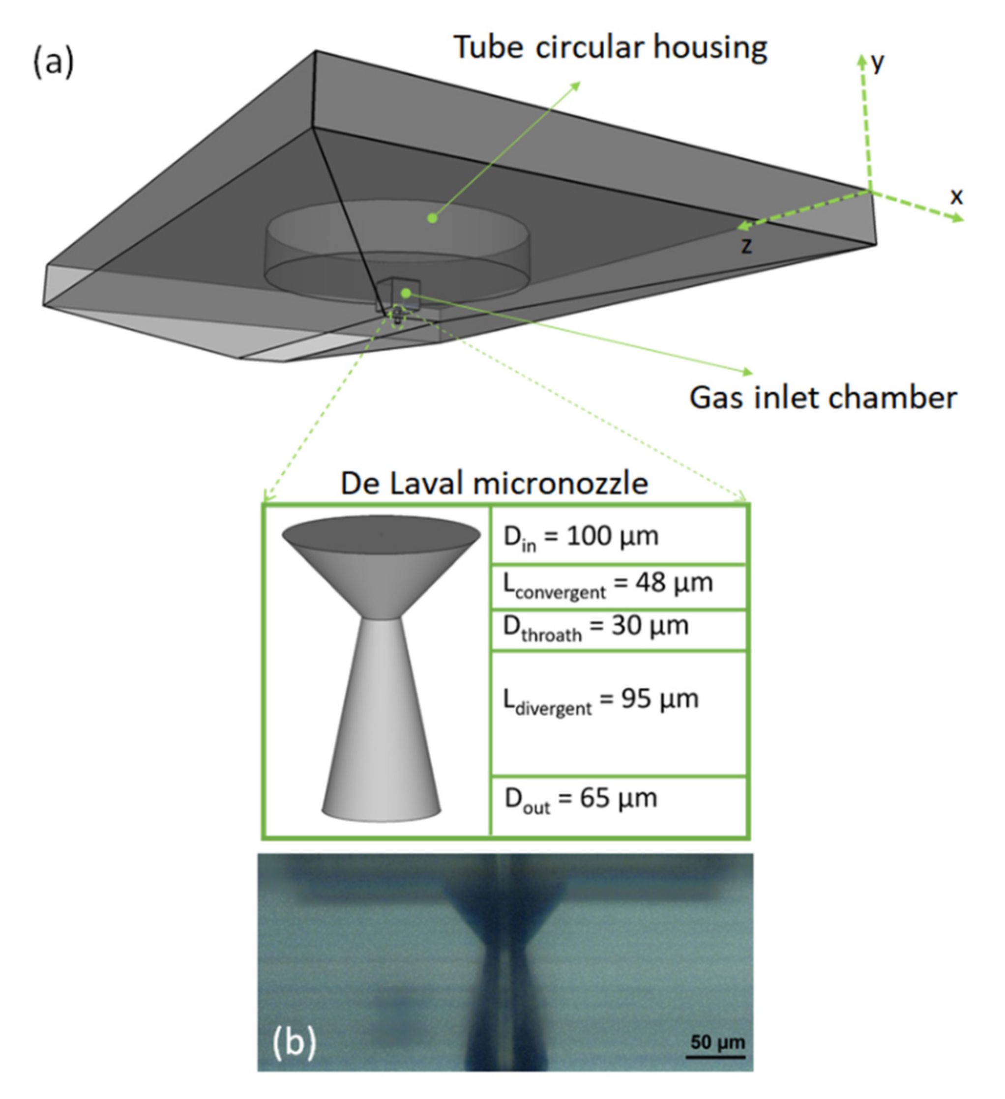
Here, we present a De Laval conical nozzle realized on a fused-silica slab through femtosecond laser irradiation followed by chemical etching (FLICE). The nozzle has been designed for application to high-order harmonic generation (HHG) [6] and ultrafast spectroscopy. In particular, it has been thought of as a component of a more complex microfluidic FLICE device aiming at achieving gas density manipulation on the micron-scale for efficient high-order harmonic generation on a chip [7]. In this work, we studied the hydrodynamic expansion of a nitrogen micro-jet in the wavefield of intense femtosecond laser pulses.
For the nozzle characterization, high-intensity femtosecond laser pulses are focused at the nozzle exit, thus, interacting with the gas jet. Driven by the oscillating laser field, the gas intercepted by the laser beam may experience ionization by electron tunneling leading to the generation of electrons correlated to the parent ions [8]. In this regime, the fluorescence emission from the ionized gas at particular wavelengths in the visible/UV spectrum can be detected. Fluorescence from molecular gases provides information on the excited states involved in the strong-field processes, but can also be used for mapping the distribution of the excited molecules on a spatial domain.
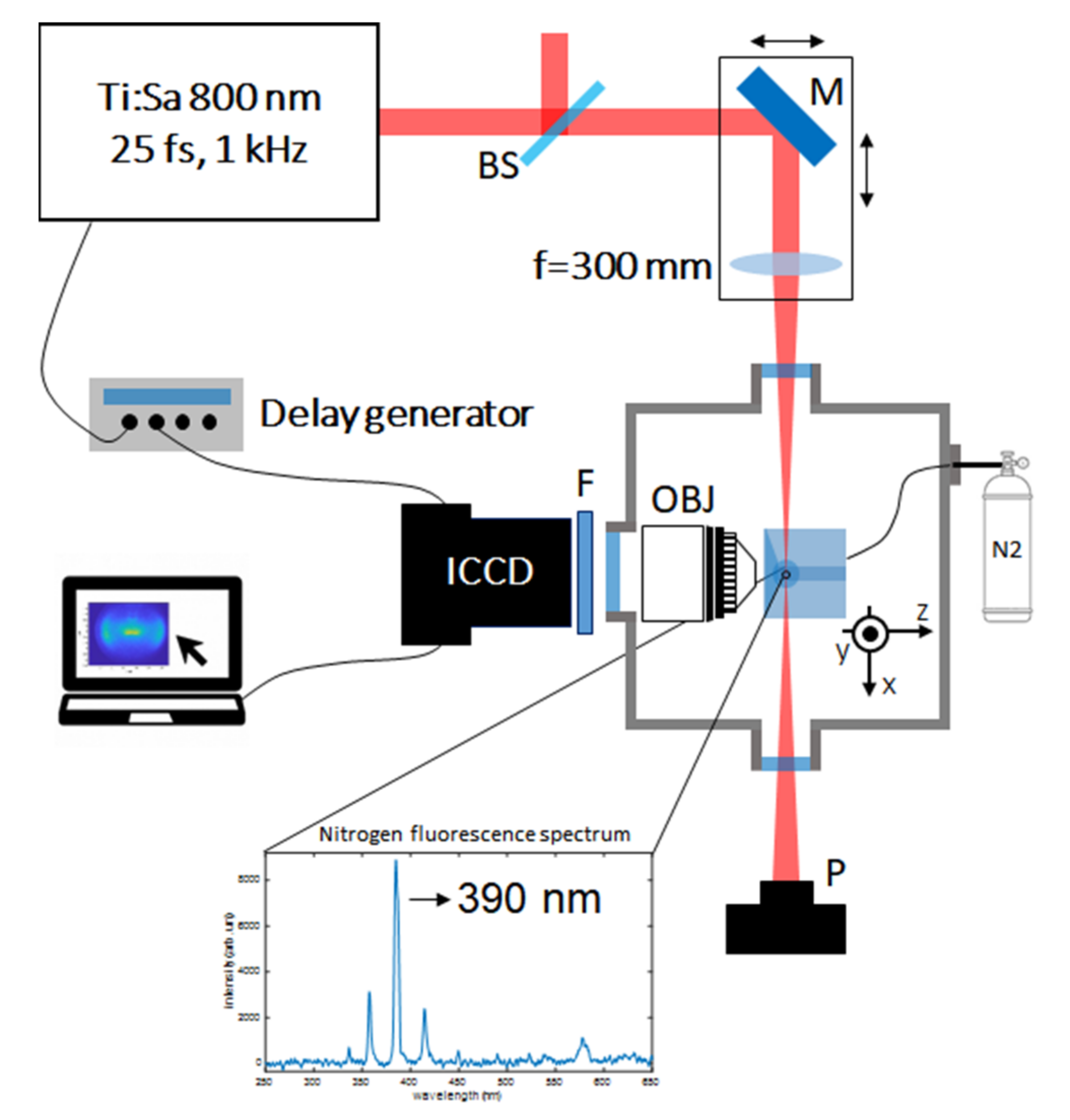
In particular, we detected the radiative emission at 391 nm from N2+(B2 Σu+) to the N2+(X2 Σg+) states through an ICCD-based imaging setup. The micro-nozzle used for nitrogen injection was engineered to allow collecting the fluorescence signal in proximity to the gas jet and orthogonally to the laser propagation direction. The dynamics of the charged particle population was measured with a time step of 5 ns.

2. Materials and Methods

2.1. Glass De Laval Nozzle Fabrication

The fused silica micronozzles were fabricated by the FLICE technique, which allows the fabrication of 3D microfluidic devices inside a glass substrate with a maskless approach [9,10]. A femtosecond laser beam is focused inside the glass substrate and, due to nonlinear processes that occur at the focal spot, the material is permanently modified, presenting a localized higher etching rate. By exposing the irradiated substrate to an etchant solution, it is possible to fabricate microfluidic networks with the desired geometry.
We used the second harmonic of a femtosecond laser beam (Satsuma HP, Amplitude). It provided pulses with a 270-fs duration at a 1-MHz repetition rate, and we used pulse energies ranging from 250 nJ to 380 nJ. We focused these pulses inside the fused silica substrate by a 63× microscope objective (0.75 numerical aperture (N.A.)) equipped with a corrective collar for spherical aberrations. The fused silica slab was mounted onto a precision 3D movement system (ANT130-035-L-ZS-PLUS and ANT95-50-XY-CMS-ULTRA from AEROTECH Inc.) that permits the movement of the sample with respect to the laser beam, with an overall 275 nm accuracy. The sample was irradiated in a bottom to top direction.
The fused silica glass chip had a trapezoidal external shape with an embedded micronozzle, as represented in the illustration in Figure 1. The external trapezoidal shape allowed the interaction of the gas jet with ultrafast laser pulses near the nozzle exit without damaging the device.
To define the gas tube reservoir and the external trapezoidal shape, the energy of the pulses used for the fabrication was fixed at 300 nJ and 380 nJ, respectively, with sample translation speeds of 2 mm/s and 5 mm/s. To shape the typical convergent-divergent tube geometry of a De Laval nozzle (see Figure 1a), the sample was irradiated following a 3D helical trajectory with a variable radius [11]. The translation speed was 0.2 mm/s and the helix pitches (Λ) were 8 µm and 2 µm in the convergent and divergent cones, respectively. The pulse energy was reduced to 250 nJ to avoid over-exposure due to the low translation speed. These irradiation conditions guaranteed a good superposition of the laser tracks.
After the irradiation, the sample was immersed in an ultrasonic bath of a 20% HF aqueous solution for 80 min to completely reveal the desired empty inner volumes. For the present work, we designed a De Laval micronozzle with the final geometric characteristics reported in the blow-up of Figure 1a,b. This device represents an example of the FLICE capabilities for the fabrication of micronozzles. Indeed, we can choose any arbitrary diameter, shape, and length for the different sections of the nozzle, considering a minimum lateral dimension of 10 µm due to HF etching selectivity [9,10,11].

2.2. Experimental Setup

For the study of the gas jet expansion dynamics, we used the experimental setup shown in Figure 2. The ultrashort laser pulses were provided by an ultrafast Ti:Sapphire laser system at 800 nm wavelength (Amplitude, Aurora laser system: 15 mJ, 25 fs, 1 KHz). A fraction of the laser pulse energy (up to 440 µJ) was used to ionize the gas, hence, triggering the plasma dynamics. We tuned the pulse energy between 150 and 400 µJ by rotating a beam splitter. The pulses were focused into a vacuum chamber by an anti-reflection coated plano-convex lens with focal length f = 300 mm. Filaments were formed in air with an elongation of ~1 cm. At the entrance, the vacuum chamber was equipped with high-optical quality fused silica windows with a thickness of 500 µm.
The nozzle was connected to the gas by a 1.5-mm inner diameter metallic tube into the glass device inlet with vacuum-compatible low-vapor-pressure epoxy glue. The metallic gas tube was interfaced with a flexible tube, thus, allowing a free motion for positioning the nozzle into the experimental chamber.
The device was mounted on top of a high-precision 3-axis motorized translation system composed of three linear stages (Newport) for accurate control of the nozzle alignment to the laser filament.
The nozzle was tested in low-pressure air environment (2 × 10⁻¹ mbar). The vacuum chamber was pumped by a dry screw pump (650 m3/hour speed). The nozzle was loaded with a continuous backing pressure, up to 3 bars. The backing pressure can be manually tuned by a needle valve mounted upstream the gas pipeline, and accurately monitored by a capacitive pressure gauge placed after such valve.
To collect the plasma signal, we used an optical system consisting of a 30× aspheric objective lens with 0.4 N.A. (Newport, 5723-A-H), rigidly screwed on an aluminum tube mounted on a KF40 flange and terminated with a fused silica window. For adjusting the laser beam position to the objective working distance, we put the mirror and the lens on a manual translational stage. The plasma dynamics were imaged orthogonally to the expansion direction by a fast gated camera. The camera is made by two units: a multi-channel plate (MCP) intensifier (C9546-03, Hamamatsu Photonics, Tokyo, Japan) coupled to a low noise CCD camera (Retiga R6, Q-imaging, Surrey, BC, Canada) by a lens system. The CCD camera (2688 × 2200 pixels) was operated at 2 × 2 binning to match the spatial resolution of the MCP (Modulation Transfer Function ≈ 1024 lines). To acquire time-resolved 2D images, we synchronized the camera acquisition with the laser pulses through a programmable time-delay generator (Stanford Research Systems, DG535). All the images were taken with gate width of 5 ns.
The spectrum emitted by nitrogen filaments in the visible down to the UV was preliminarily measured in air; a strong emission line from N2+ at 391 nm was detected. This spectral component was selected by using a 5-nm bandwidth interferometric filter at 391 nm (Thorlabs) placed at the entrance of the ICCD.

3. Study of the Plasma Expansion Dynamics

The interaction of the gas sample with the femtosecond pulses leads to the generation of a population of high-energy electrons through multiphoton ionization and electron tunnel ionization [12]. The laser-induced ionization of the gas occurs on the time scale of the pulse duration, which is significantly shorter than the characteristic gas dynamic response of the neutrals and ions undergoing expansion (≥10 ns). The kinetics of the plasma, thus, occurs under field-free conditions and involves different interaction channels among the gas species (neutrals, ions and electrons), including electron impact ionization, electron–ion recombination, and dissociative recombination [13]. In femtosecond laser filaments, the plasma decay by collisional mechanisms mainly depends on the gas density and composition; it is commonly on the scale of tens of nanoseconds [14]. In turn, the kinetics of a plasma population governs the radiative lifetime of the emitting species. In the specific case of the 391-nm N2+ component, the lifetime in a filament driven by femtosecond pulses in vacuum ranges from a few nanoseconds up to tens of nanoseconds [15,16]. In a 2D fluorescence image the information on the density distribution of the emitting species is not directly related to the intensity distribution of the fluorescence, due to the collective nature of the radiative process. Indeed, the decay of excited molecules is due to both radiative and non-radiative deactivation processes, such as collisions. In this sense, the rates of radiative ( k r ) and non-radiative ( k n r ) decay mechanisms determine the emission quantum yield ϕ = k r / ( k r + k n r ), which, in turn, is strongly related to the fluorescence lifetime by τ = ϕ / k r [17]. The collisional deactivation rates mainly depend on the gas density and the mean velocity of the interacting particles, namely, on the gas temperature [18,19]. To evaluate the radiative behaviour of a plasma generated in a non-uniform gas medium, information on the electron/ion density and temperature distributions within the plasma is required. For this purpose, which is beyond the scope of our work, several techniques can be used in combination with 2D fluorescence imaging, including optical interferometry [20,21], terahertz-based scattering [20], and pump-probe fluorescence spectroscopy [22].
To study the gas jet behavior, we traced the spatial distribution of the plasma produced by 25-femtoseconds laser pulses through the collision-mediated decay of nitrogen ions fluorescence at 391 nm. We imaged the temporal evolution of the gas excited by the 25-fs pulses, on the timescale of tens of nanoseconds, for various times after plasma onset by steps of 5 ns. 
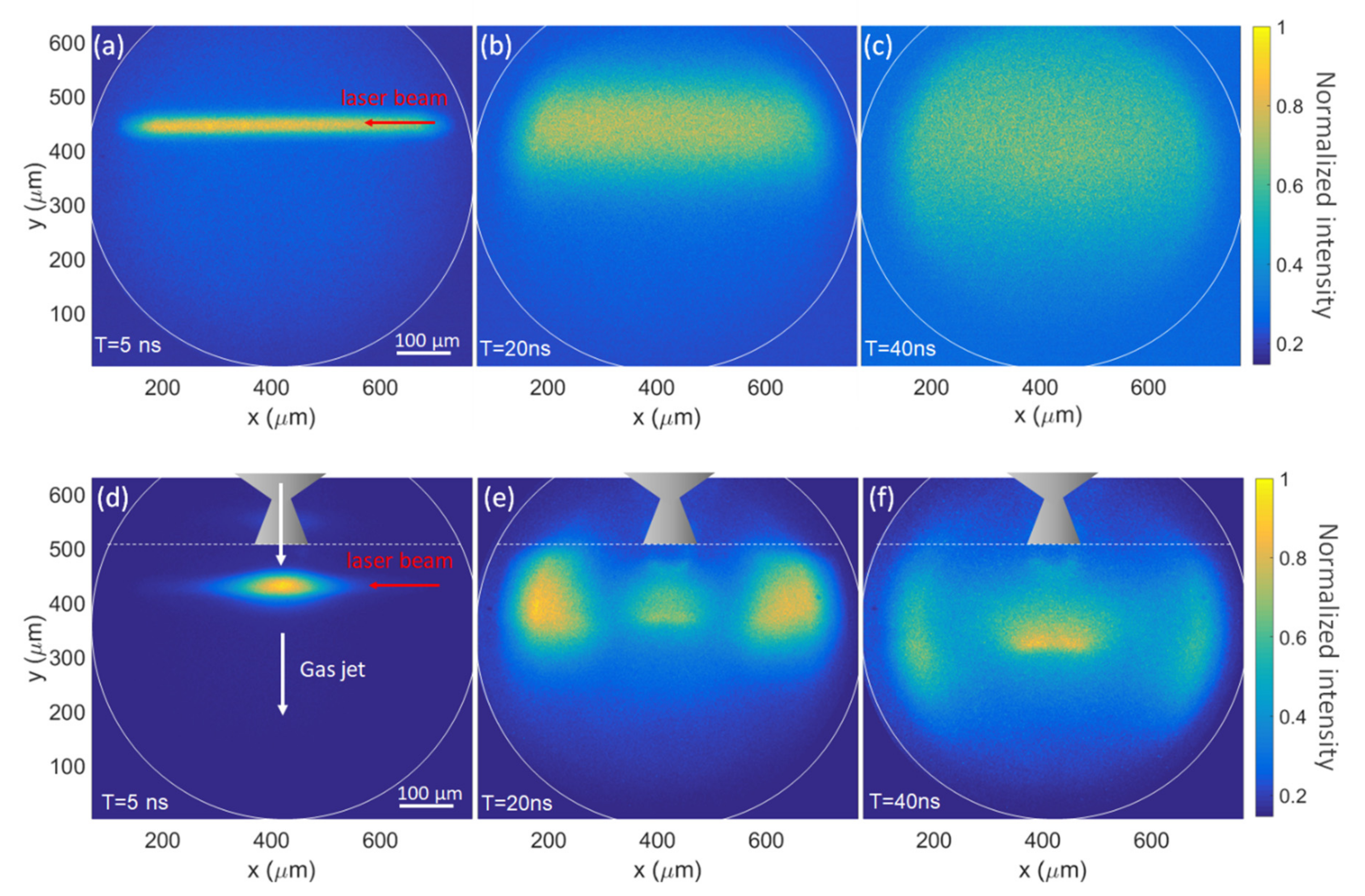
Figure 3 reports the frames detected at selected delays from the laser arrival, showing the fluorescent spatial distribution of the nitrogen plasma in two different conditions, with and without the gas flux from the micronozzle.
With the scope to separate the effect of vacuum environment gas diffusion from the expansion of gas jet, we preliminarily evaluated the fluorescence emitted in a 2 × 10⁻¹ mbar vacuum environment by detecting the whole filament emission intensity in vacuum (with no gas flux from the micronozzle) as a function of time. In our experimental conditions, we measured a radiative decay characterized by an intensity peak after 10 ns from the laser arrival, followed by an exponential decrease with a lifetime of 45 ns. The observation of an intensity peak delayed by 10 ns from the laser excitation suggests the early activation of non-radiative contribution and might be attributed to the effect of plasma growing under the excitation by secondary electrons. After 10 ns, the effect of secondary electrons extinguishes. In this pressure conditions, the mean free path of nitrogen molecules is estimated on the few hundreds of micrometers scale (~300 µm). Herein, collisional mechanisms play a minor role, and the characteristic fluorescence lifetime is attributed to a purely radiative decay. Figure 3a–c display the radial diffusion of a portion of the plasma filament (the field of view of the imaging system ~500 µm). The laser propagation direction is orthogonal to the camera position and the pulse arrival time is conventionally indicated as T = 0. After 5 ns from the pulse arrival, the fluorescence emission from the ionized molecules is strongly confined, approximately a cylinder with a diameter w = 21 µm calculated as the full width at half-maximum of the Gaussian fit along the direction orthogonal to the laser propagation. Since in the first few nanoseconds after the laser arrival, the plasma kinetics can be assumed almost isochoric; the fluorescence emission at 5 ns delay provides a reasonable estimation of the initial dimension of the plasma, with w being approximately the radial extension of the gas volume ionized by the femtosecond pulses.
At longer delays ( 10 ns), the fluorescence signal spreads under the pressure increase inside the high-temperature conductive plasma. The radial diffusion is mainly related to the energy of the laser pulses and gas pressure [14]. Upon femtosecond laser excitation, the typical response of a low-pressure air filament is expected to produce a rapid growth of the plasma, associated with a radial increase of the nitrogen ions volume of a few microns on a time scale of a few nanoseconds. Monte Carlo simulations of nearly free molecular expansion of a hot gas column into the low-pressure cold nitrogen background, indicate that the observed time evolution of gas fluorescence is compatible with an initial gas temperature in the range of (5000–10000) K. The fluorescence propagation is dominated by individual molecule motion, the average advection velocity being much smaller than the molecular thermal speed.
The expansion of the plasma generated in a gas jet was explored by using the same scheme. We positioned the glass nozzle in the laser focus at a distance d = 80 µm from the laser beam (y-direction). The focal length of the focusing mirror provides a Rayleigh range much longer than the radial size of the nozzle, thus, allowing for a uniform excitation of the gas jet along the beam propagation direction (x in Figure 2), inside the interaction region. The nozzle was loaded with a nitrogen backing pressure of 3 bar. Preliminary numerical microfluidic calculations, performed with Comsol Multiphysics® [23], indicate that, in steady conditions, the axial velocity of the gas jet produced by the glass nozzle ranged between 620 m/s and 730 m/s from the nozzle outlet to a 100 µm distance, along the jet axis. Herein, the steady pressure ranged from 9 × 10² mbar to 1.6 × 10² mbar. Based on the nozzle geometry (circular throat and output with diameters respectively of 30 and 65 µm), the gas jet is expected to have a circular section in the transversal plane. From the Comsol calculations, the diameter at a beam distance d will be 85 µm, thus, exceeding the radial extension of the plasma volume ( w ~21 µm). In this configuration, only a small portion of the gas jet is ionized by the ultrashort pulses.
Figure 3d–f report time-delayed 2D maps of the nitrogen fluorescence by filamentation in the gas jet. The gas flux is directed downwards according to the image orientation.
The high nitrogen density in the focused jet produces a local increase of fluorescence intensity. At T = 5 ns, the signal intensity is enhanced by almost two orders of magnitude compared to the fluorescence of the filament in vacuum (Figure 3a). In particular, the intensity on the peak is higher by a factor of 76 as compared to the intensity along the plasma filament. In Figure 3d, the fluorescence emitted along the whole filament is not visible as in Figure 3a, since the camera gain was tuned for acquiring the bright emission form the gas-jet volume.
The high local density in the region corresponding to the gas jet strongly influenced the spatial evolution of the plasma at later delays, as suggested by the 20 ns and 40 ns delayed frames. The gas flux at the exit of the nozzle modifies the isotropic gas expansion with the appearance of a high-intensity fluorescence pattern centered on the gas jet. We expect a non-uniform fluorescence lifetime depending on the local gas density and temperature along the filament. In particular, we predict a significantly high contribution of non-radiative decay channels in the gas-jet region. Due to the non-uniform fluorescence properties, the 2D fluorescence yield of a plasma in a gas jet does not provide direct information on the gas density. However, structural information on the evolution of the laser-induced plasma can be obtained from the morphology of the fluorescence distribution. In particular, the 2D maps indicate the formation of a shock wave, associated with the generation of spatial regions with lower and higher gas density. The density wave propagated from the bulk of the excited volume isotropically, as suggested by the spherical-like shape of the low-intensity zone. In Figure 3e,f, two bright lobes rise at the sides of the jet and undergo a rapid lateral displacement. These two lobes correspond to low-density regions, where the fluorescence lifetime was longer and the quantum yield higher than in the jet, thus, appearing brighter at longer delays.
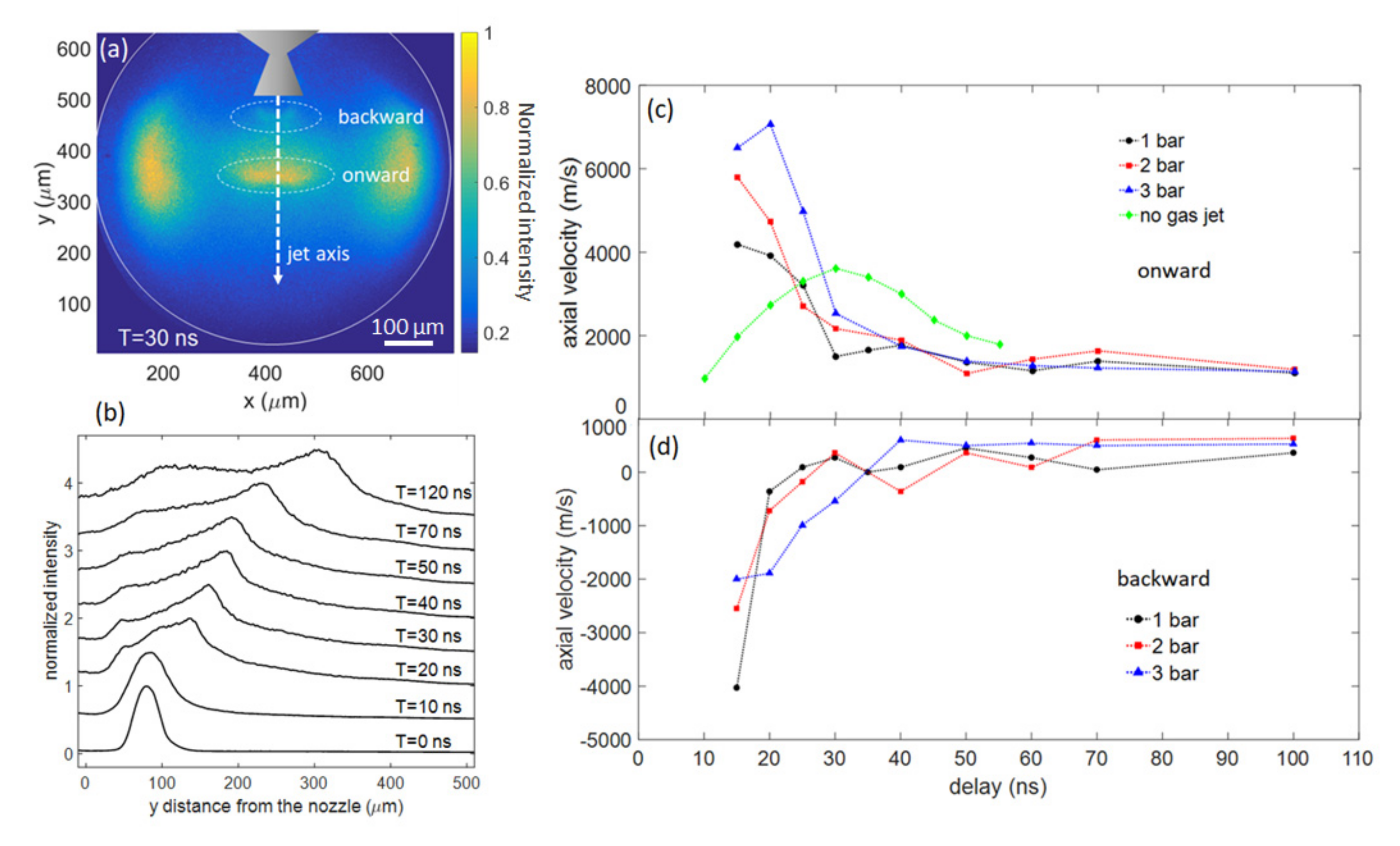
The plasma plume confined in the central region corresponding to the gas jet evolved under the combined effect of the internal force driving expansion and external gas flux. As time increased, the plume underwent both a spatial spreading and a splitting into two different front-waves, a brighter fluorescent feature downwards and a less intense feature closer to the nozzle (see Figure 4a). The bright peak moved onwards along the gas-jet axis. On the other hand, the second peak was initially propagating towards the nozzle position, and underwent a direction reversal after ~40 ns, under the effects of the nitrogen flux from the nozzle. These two components follow different dynamics, both in terms of fluorescence decay and time-dependent propagation velocity. For sake of comparison, we report in Figure 4b the intensity profiles along the gas jet axis as a function of the distance from the nozzle output at different time delays. At early times, the intensity distribution is composed of one peak, spatially spreading while propagating away from the nozzle. For T ≥ 15 ns, the two counter-propagating waves rise, associated with two well-defined intensity peaks. The fluorescence underwent a rapid decay, with a characteristic lifetime <5 ns, due to the shorter lifetime of excited nitrogen states upon the higher frequency of collisions in a dense gas jet. However, the difference between the intensity of the two wavefronts reduced in time, suggesting a faster radiative decay of the downwards component.
To quantify the plume expansion dynamics, we determined the position of the two peaks from the intensity profiles and estimated the propagation velocity, as provided in Figure 4c,d. Both the two wavefronts experienced a fast transitory regime, during which the propagation velocity reached values up to 7 × 10³ m/s and 5 × 10³ m/s for the onwards and the backward components, respectively. The velocity peak ranged between 15 ns and 20 ns from the pulsed excitation. At longer delays, the velocity converges towards a steady value. Compared to the unperturbed filament (green curve in Figure 4c), plasma generation in a gas flux produced both faster expansion dynamics and higher propagation velocities. In this framework, we explored the dependence of both the onward and the backward shock wave components on the gas flux by changing the nitrogen backing pressure. Upon increasing the backing pressure, the onward component underwent an increase of the expansion velocity. On the other hand, the increasing directional force opposed by the gas-jet on the propagation of the backward component produces a slower transitory response and a lower peak expansion velocity. This pressure dependence mainly affected the initial expansion dynamics by 40 ns, up to the dissipation of the thermodynamic forces driving the plasma expansion.
Besides gas density, the plasma dynamics depend on the energy deposited in the ionized gas, which scales with the energy of the femtosecond laser pulses. 
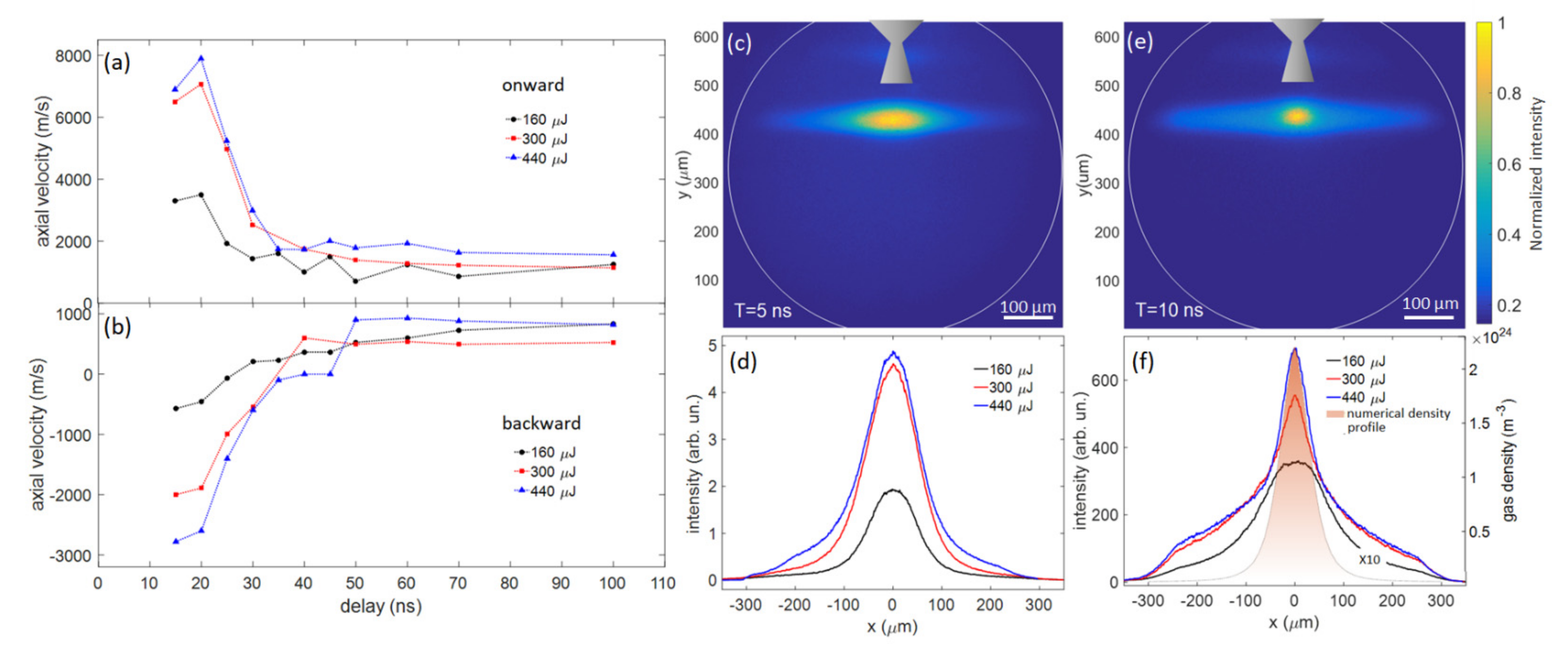
Figure 5a,b provide the axial velocity of the two shock waves for different pulse energies (160 µJ, 300 µJ, 440 µJ) at a fixed backing pressure of 3 bar. The onward and backward waves depend monotonically on the amount of energy transferred by the laser pulses, displaying an increase of the expansion velocity upon increasing pulse energy. We also observed a non-linear dependence of the fluorescence yield with the pulse energy. Figure 5c,e show the fluorescence distribution for 440-µJ pulse energy at delays 5 and 10 ns, respectively; herein a counterintuitive spatial reshaping of the fluorescence distribution can be noticed, from an elongated to a more focused bright spot. For these two delays, in Figure 5d,f we report the intensity profiles along the x-direction at different pulse energies. At a 5-ns delay, the fluorescence emission consists of bell-like amplitude-scaled spatial profiles. By increasing the pulse energy from 160 to 300 µJ, the fluorescence yield scaled almost proportionally, while, from 300 to 440 µJ it exhibited a saturation associated with no remarkable increase in the measured intensity. Instead, at a 10-ns delay, different pulse energies produced a considerably different fluorescence yield, which increased by more than one order of magnitude from 160 to 300 µJ, and a spatial modulation of the fluorescence distribution, which led to a locally enhanced emission. In particular, the intensity profile along the laser propagation direction (x-axis) showed strong confinement resulting in the appearance of a narrow intensity peak at high pulse energies. Interestingly, we found a correlation between the narrow fluorescence peak, rising at high pulse energy and the gas density profile as resulting from numerical microfluidics calculations in unperturbed conditions, namely, those unaffected by the laser field. In particular, this peak was delayed with respect to the laser pulse and progressively matched the steady-state density profile as the pulse energy increased, thus, retaining information on the gas jet spatial properties preceding the plasma expansion. This behaviour suggests the activation of a different plasma decay regime depending on the energy deposited by the driving laser pulse. In a high-energy regime, Coulomb collisions among electrons start playing a crucial role due to the high density of electrons [24]. The difference in the spatial velocity distributions of heavy ions and light electrons become higher, leading to space-charge effects that affect the recombination efficiencies governing the fluorescence lifetime. In this sense, a detailed kinetic approach would be required to simulate the plasma population evolution during the expansion and to locally evaluate the radiative decay parameters as a function of the spatial properties of the plasma.
Even though the gas dynamics and the space-charge effects were in a time scale (ns) that does not affect ultrafast laser nonlinear interactions with gas in the kHz regime (Trep ~ms), it has been demonstrated that, at a higher repetition rate their role is crucial. In this case, the pulse train may induce a cumulative ionization in the interaction volume leading to a steady-state plasma. The study of plasma accumulation effects is of fundamental interest for applications as XUV frequency comb generation by HHG [25]. This time-resolved 2D fluorescence imaging constitutes a powerful tool for exploring the time-resolved spatial evolution of laser-induced ionization in gas.

4. Conclusions

In this work, we applied time-resolved 2D fluorescence imaging for tracking the spatial evolution of a nitrogen plasma driven by high-energy femtosecond laser pulses. Plasma dynamics are ubiquitous in ultrafast high-energy laser-matter interactions and might significantly affect the process under investigation. In this framework, the role of plasma in high-order harmonic generation inside a gas jet is of fundamental importance, especially when high repetition rate lasers are used for driving the process. In this framework, we fabricated glass de Laval micro-nozzles by femtosecond laser micromachining, followed by chemical etching. We investigated the expansion dynamics of the plasma generated in the gas microjet at different gas pressures and pulse energies by measuring the spatial distribution of the N2+ fluorescence at 391 nm. The measured fluorescence maps allowed us to investigate the morphology and the propagation of ions shockwaves upon continuous gas flux on a nanosecond timescale. The strong coupling between the radiative decay mechanism and the kinetics of plasma species fundamentally affects the possibility to exploit the 2D imaging scheme to fully characterize the plasma properties. On the other hand, the use of this technology coupled with conductivity and interferometric measurements, as well as spectrally-resolved approaches, will offer the potentials for achieving a deeper understanding of laser-induced plasma physics, addressing interest in many research fields, including surface treatment, high-energy physics, and ultrafast optics.

Author Contributions

Conceptualization, A.F., S.S., C.V., R.O., A.G.C. and R.M.V.; validation, A.G.C., R.M.V., G.V., D.C., M.D. and G.C.; formal analysis, A.F., A.G.C., R.M.V. and G.V.; investigation, A.G.C., R.M.V., G.V., D.C., M.D. and G.C.; writing—original draft preparation, A.G.C., R.M.V. and A.F. writing—review and editing, all authors; supervision, S.S., C.V., R.O.; funding acquisition, R.O., S.S., C.V., M.D. and R.M.V. All authors have read and agreed to the published version of the manuscript.

Funding

This project has received funding from the European Unions Horizon 2020 research and innovation program under grant agreement No 964588 (X-PIC), by the Italian Ministry of Research and Education with the projects ELI ESFRI Roadmap and PRIN aSTAR (2017RKWTMY), by the Consiglio Nazionale delle Ricerche with the Joint Laboratory ATTOBIO.

Informed Consent Statement

Not applicable.

Data Availability Statement

All data needed to support the conclusions of the paper are present in the text. Raw data are available upon request.

Conflicts of Interest

The authors declare no conflict of interest. The funders had no role in the design of the study; in the collection, analyses, or interpretation of data; in the writing of the manuscript, or in the decision to publish the results.

References

  1. Niculescu, A.G.; Chircov, C.; Bîrcăe, A.C.; Grumezescu, A.M. Fabrication and Applications of Microfluidic Devices: A Review. Int. J. Mol. Sci. 2021, 22, 2011. [Google Scholar] [CrossRef] [PubMed]
  2. Zhang, S.; Wang, Y.; Onck, P.; Toonder, J.D. A concise review of microfluidic particle manipulation methods. Microfluidics Nanofluidics 2020, 24, 24. [Google Scholar] [CrossRef] [Green Version]
  3. Even, U. Pulsed Supersonic Beams from High Pressure Source: Simulation Results and Experimental Measurements. Adv. Chem. 2014, 2014, 1–11. [Google Scholar] [CrossRef] [Green Version]
  4. Heyl, C.; Schoun, S.B.; Porat, G.; Green, H.; Ye, J. A nozzle for high-density supersonic gas jets at elevated temperatures. Rev. Sci. Instrum. 2018, 89, 113–114. [Google Scholar] [CrossRef] [PubMed] [Green Version]
  5. Sugioka, K.; Xu, J.; Wu, D.; Hanada, Y.; Wang, Z.; Cheng, Y.; Midorikawa, K. Femtosecond laser 3D micromachining: A powerful tool for the fabrication of microfluidic, optofluidic, and electrofluidic devices based on glass. Lab. Chip. 2014, 14, 3447–3458. [Google Scholar] [CrossRef] [PubMed]
  6. Ciriolo, A.G.; Vázquez, R.M.; Tosa, V.; Frezzotti, A.; Crippa, G.; Devetta, M.; Faccialá, D.; Frassetto, F.; Poletto, L.; Pusala, A.; et al. High-order harmonic generation in a microfluidic glass device. J. Phys. Photonics 2020, 2, 024005. [Google Scholar] [CrossRef]
  7. Ciriolo, A.G.; Vázquez, R.M.; Roversi, A.; Frezzotti, A.; Vozzi, C.; Osellamee, R.; Stagira, S. Femtosecond Laser-Micromachining of Glass Micro-Chip for High Order Harmonic Generation in Gases. Micromachines 2020, 11, 165. [Google Scholar] [CrossRef] [Green Version]
  8. Lin, C.D.; Le, A.T.; Jine, C.; Wei, H. Attosecond and Strong-Field Physics: Principles and Applications; Cambridge University Press: Cambridge, UK, 2018. [Google Scholar]
  9. Gattass, R.R.; Mazur, E. Femtosecond laser micromachining in transparent materials. Nat. Photonics 2008, 2, 219–225. [Google Scholar] [CrossRef]
  10. Osellame, R.; Hoekstra, H.; Cerullo, G.; Pollnau, M. Femtosecond laser microstructuring: An enabling tool for optofluidic lab-on-chips. Laser Photon-Rev. 2011, 5, 442–463. [Google Scholar] [CrossRef]
  11. Vishnubhatla, K.C.; Bellini, N.; Ramponi, R.; Cerullo, G.; Osellame, R. Shape control of microchannels fabricated in fused silica by femtosecond laser irradiation and chemical etching. Opt. Express 2009, 17, 8685–8695. [Google Scholar] [CrossRef]
  12. Corkum, P. Plasma perspective on strong field multiphoton ionization. Phys. Rev. Lett. 1993, 71, 1994–1997. [Google Scholar] [CrossRef] [PubMed] [Green Version]
  13. Kartashov, D.; Ališauskas, S.; Pugzlys, A.; Shneider, M.N.; Baltuška, A. Theory of a filament initiated nitrogen laser. J. Phys. B At. Mol. Opt. Phys. 2015, 48, 94016. [Google Scholar] [CrossRef]
  14. Aleksandrov, N.L.; Bodrov, S.B.; Tsarev, M.V.; Murzanev, A.; Sergeev, Y.A.; Malkov, Y.A.; Stepanov, A.N. Decay of femtosecond laser-induced plasma filaments in air, nitrogen, and argon for atmospheric and subatmospheric pressures. Phys. Rev. E 2016, 94, 013204. [Google Scholar] [CrossRef] [PubMed]
  15. Wang, P.; Xu, S.; Li, D.; Yang, H.; Jiang, H.; Gong, Q.; Wu, C. Spectroscopic study of laser-induced tunneling ionization of nitrogen molecules. Phys. Rev. A 2014, 90, 033407. [Google Scholar] [CrossRef]
  16. Ran, P.; Li, G.; Liu, T.; Hou, H.; Luo, S.-N. Collision-mediated ultrafast decay of N2 fluorescence during fs-laser-induced filamentation. Opt. Express 2019, 27, 19177–19187. [Google Scholar] [CrossRef]
  17. Lakowicz, J.R. Principles of Fluorescence Spectroscopy; Springer Science & Business Media: Boston, MA, USA, 2006. [Google Scholar]
  18. Waldenmaier, T.; Blümer, J.; Klages, H. Spectral resolved measurement of the nitrogen fluorescence emissions in air induced by electrons. Astropart. Phys. 2008, 29, 205–222. [Google Scholar] [CrossRef] [Green Version]
  19. Arqueros, F.; Blancoe, F.; Rosado, J. Analysis of the fluorescence emission from atmospheric nitrogen by electron excitation, and its application to fluorescence telescopes. New J. Phys. 2009, 11, 065011. [Google Scholar] [CrossRef]
  20. Bodrov, S.; Bukin, V.; Tsarev, M.; Murzanev, A.; Garnov, S.; Aleksandrov, N.; Stepanov, A. Plasma filament investigation by transverse optical interferometry and terahertz scattering. Opt. Express 2011, 19, 6829–6835. [Google Scholar] [CrossRef]
  21. Chien, C.Y.; La Fontaine, B.; Desparois, A.; Jiang, Z.; Johnston, T.W.; Kieffer, J.C.; Pépin, H.; Vidal, F.; Mercure, H.P. Single-shot chirped-pulse spectral interferometry used to measure the femtosecond ionization dynamics of air. Opt. Lett. 2000, 25, 578–580. [Google Scholar] [CrossRef]
  22. Martirosyan, A.E.; Altucci, C.; Bruno, A.; De Lisio, C.; Porzio, A.; Solimeno, S. Time evolution of plasma afterglow produced by femtosecond laser pulses. J. Appl. Phys. 2004, 96, 5450. [Google Scholar] [CrossRef]
  23. COMSOL Multiphysics® v. 5.6. COMSOL AB: Stockholm, Sweden. Available online: www.comsol.com (accessed on 11 February 2021).
  24. Shneider, M.; Zheltikov, A.; Miles, R. Tailoring the Air Plasma with Double Laser Pulses. Phys. Plasmas 2011, 18, 063509. [Google Scholar] [CrossRef] [Green Version]
  25. Porat, G.; Heyl, C.; Schoun, S.; Benko, C.; Dörre, N.; Corwin, K.; Ye, J. Phase-Matched Extreme-Ultraviolet Frequency-Comb Generation. Nat. Photonics 2018, 12, 387–391. [Google Scholar] [CrossRef]
Figure 1. (a) Illustration of the De Laval nozzle chip. The top circular housing holds the gas inlet tube (glued to it). In the blow-up image the dimensions of the de Laval nozzle are reported. The three-axis reference system we refer to within the article, is reported above. (b) Transmission microscope image of the De Laval nozzle used in the experiments reported in the manuscript.
Applsci 12 01978 g001
Figure 2. Experimental setup used to image the laser-excited gas dynamics. Ultrashort laser pulses were focused on the gas jet by a 300-mm focal lens. The pulse energy was modulated by a beam-splitter (BS) mounted on a rotational stage and measured by a power meter (P). The fluorescence emitted by the ionized nitrogen was collected through an ICCD interfaced with an aspheric objective (OBJ). A UV bandpass interferometric filter (F) was used to select the emission line at 391 nm. Time-resolved frames are collected by triggering the camera with a delay generator. (M) Movable mirror-lens assembly. The insert shows the fluorescence spectrum emitted by nitrogen excited with femtosecond laser pulses.
Applsci 12 01978 g002
Figure 3. (ac) show the expansion at different time delays of a plasma filament generated by femtosecond laser pulses in vacuum (2 × 10⁻¹ mbar). 300 µJ pulses with 25-fs duration were focused in the vacuum chamber by a 300-mm focal lens. (df) show the evolution of the plasma by adding a nitrogen flux through a micronozzle loaded with a backing pressure of 3 bar. The nozzle illustration is not to scale. Each frame is normalized to the peak intensity. For each delay, the camera gain is optimized for compensating to the decay of the fluorescence.
Applsci 12 01978 g003
Figure 4. (a) 30-ns delayed frame showing the splitting between the onward and the backward wavefronts. (b) Fluorescence profiles along the jet axis at several delays up to 120 ns. The intensity of each curve is normalized to the peak value. (c,d) axial velocity evolution for the onward and backward components, respectively. The propagation velocity is evaluated at three different gas pressures (1 bar, 2 bar, 3 bar). For sake of comparison, the green line shows the radial expansion velocity of the filaments in the absence of gas flux.
Applsci 12 01978 g004
Figure 5. (a,b) display the axial velocity evolution of the two wavefronts at different femtosecond pulse energies and fixed gas pressure (3 bar); (c,e) show the fluorescence generated by a 400-µJ laser pulse after 5-ns and 10-ns delays, respectively. Nozzle illustrations are on scale. (d,f) show the x-axis intensity profiles obtained by integrating the 2D fluorescence maps in the y-direction for different laser pulse energies at a 5-ns and 10-ns delays, respectively. In panel (f), the black curve is magnified by a factor 10. After 10 ns, a narrow intensity peak rises at high energy, which reproduces the numerical gas density profile provided by the micronozzle at 3 bar.
Applsci 12 01978 g005
Publisher’s Note: MDPI stays neutral with regard to jurisdictional claims in published maps and institutional affiliations.

