Article

Digital Photoelastic Analysis of TAD-Supported Maxillary Arch Distalization

1
Department of Orthodontics, Tokyo Dental College, Tokyo 1010061, Japan
2
Advanced Orthodontic Program, Herman Ostrow School of Dentistry, University of Southern California, Los Angeles, CA 90089, USA
*
Author to whom correspondence should be addressed.
Appl. Sci. 2022, 12(4), 1949; https://doi.org/10.3390/app12041949
Submission received: 10 January 2022 / Revised: 8 February 2022 / Accepted: 9 February 2022 / Published: 13 February 2022
(This article belongs to the Special Issue Recent Developments in Orthodontics on Craniofacial Orthopedics)

Abstract

:

Featured Application

This study examined the dynamics of the dentition when the dentition was moved backward with TAD using photoelasticity.

Abstract

The objective of this study was to determine whether the distribution of compressional and tensional stress around tooth roots is influenced by the position of a temporary anchorage device and the length of the retraction hook during the distalization of the maxillary dentition. A photoelastic orthodontic model was made of photoelastic epoxy resin. Six combinations of three retraction hook lengths and two posterior Temporary skeletal anchorage devices (TAD) positions were established. Stress was applied through an elastic chain for each of the combinations. Digital photoelastic stress analysis measured the compression, tensional stress, and direction around the tooth root. Using this novel photoelastic model, we found that the distribution of compressional and tensional stress during the retraction of the maxillary dentition was significantly influenced by the position of the TAD and the length of the retraction hook.

1. Introduction

Several intraoral devices have been reported for the distalization of maxillary molars to achieve non-extraction treatment [1,2,3,4,5]. However, the mesial movement of anterior teeth was inevitable because of the reaction force generated by the molar distal movement [1,2,3,4,5]. Temporary skeletal anchorage devices (TAD) have made it possible to distalize molars without mesial movement of the anterior teeth. Sugawara et al. [6] reported that maxillary molar distalization using the Skeletal Anchorage System (SAS), a plate-type anchor, did not mesialize the anterior teeth. Other reports [7,8,9,10,11,12,13,14] have demonstrated distalization appliances used with TAD.
However, this method is not without similar untoward effects, and unexpected molar movements, such as tilting, translation, and other vertical movements, can occur. In addition, this system is difficult to study both in vivo and in vitro. Nakamura et al. [15] evaluated stress on the tooth root when using a TAD for mandibular molar retraction using a photoelastic model. Kojima et al. [16] studied the biomechanics of the sliding mechanism after tooth extraction using a 3D finite element method (FEM). However, no studies have explicitly looked at the retraction of the maxillary dentition with photoelastic analysis.
Two commonly applied methods for studying biomechanical stress are the photoelastic and finite element methods. Each has advantages and disadvantages. [17,18] The photoelastic method has the advantage of more closely replicating clinical settings (it is a physical model). However, it is a type of qualitative analysis in contrast to FEM (virtual/theoretical model), which provides quantitative data. However, recent advancements in technology have led to the creation of a digital photoelastic method; with this new method, quantitative analysis is now possible with measurements of compressional and tensional stress as in FEM. In the analysis of the biomechanical forces used in clinical orthodontics, this model, therefore, has great potential.
The objective of this study was to determine whether the distribution of compressional and tensional stress around tooth roots is influenced by the position of the TAD and length of the retraction hook during the retraction of maxillary dentition using the digital photoelastic strain measurement system.

2. Materials and Methods

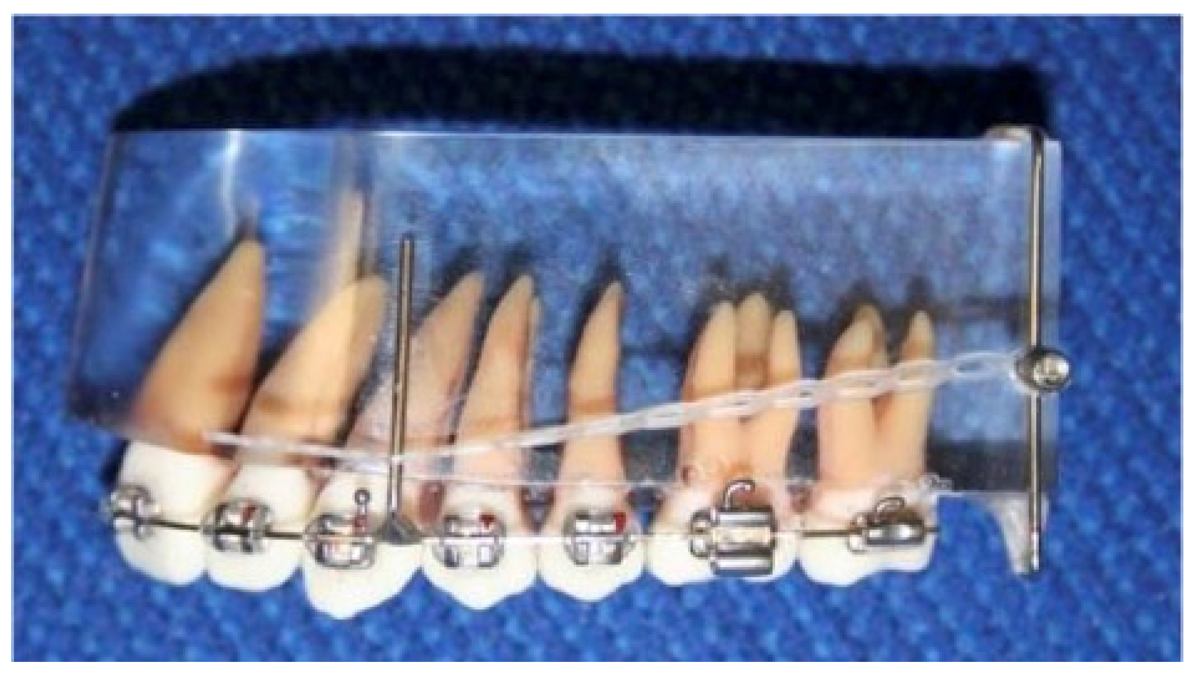
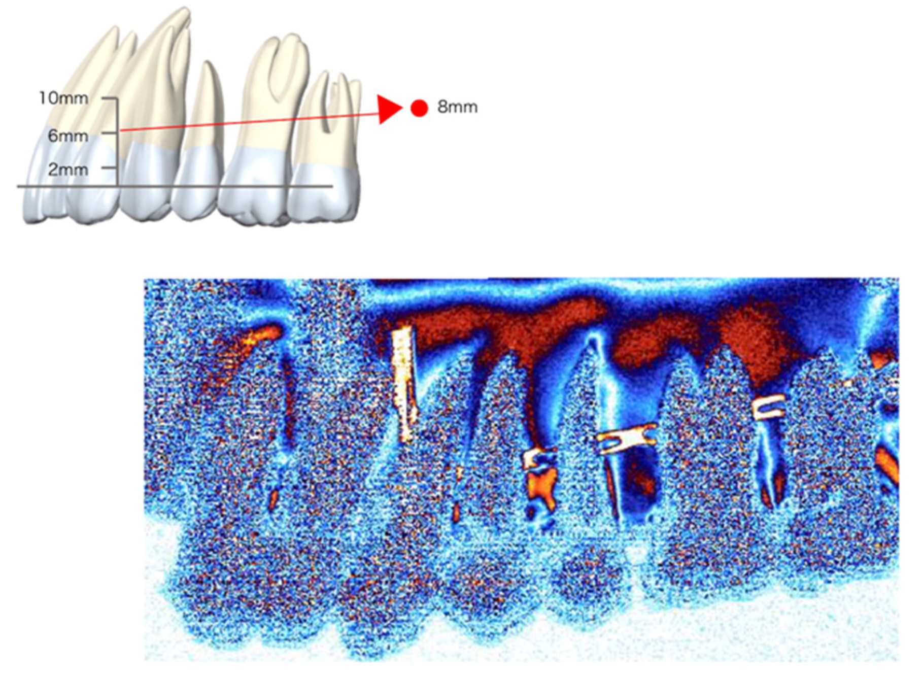
2.1. Photoelastic Model

A photoelastic model of the left maxillary dentition was used for this study. The model was created as follows. Epoxy anatomical teeth models (Anatomical Tooth Model, B2-306, Nissin, Kyoto, Japan) were used as artificial teeth. To reproduce normal occlusion during treatment, pre-adjusted edgewise brackets with 0.018-inch slots were bonded to the facial axis point, which is considered to be the appropriate bracket position [19,20] of each artificial tooth, and a 0.017 × 0.025-inch stainless steel archwire was inserted and fixed to the brackets with elastic chains. This was the model representing normal occlusion after orthodontic treatment. An alveolar wax form with an actual width of 10 mm of the left maxillary dentition was fabricated to match the model. An impression was made using polyvinyl siloxane. The impression material was removed from the alveolar wax form area, and epoxy resin (Devcon ET-300, ITW performance polymer, Osaka, Japan) was poured into the area to create an elastic model. As a result, a photoelastic model consisting of a bracket, wire, and alveolar bone made of epoxy resin and teeth was fabricated (Figure 1).
A retraction hook was soldered to the wire between the canines and first premolars. A 0.045-inch stainless steel wire with a posterior anchor was attached to the model 10 mm distally from the maxillary second molar. By changing the posterior anchor position, we simulated various retraction positions. For example, retraction may vary when using a plate-type anchor [6,21], since it is possible to alternate the vertical position with the three hooks or use a miniscrew implant anchor, since its placement is limited by inter root space [22,23].
An elastic chain was attached from the retraction hook to the posterior anchor, and stress of 200 g was applied (Figure 1). There were six combinations with three retraction hook lengths (2 mm, 6 mm, and 10 mm) and two posterior anchor positions (2 mm and 8 mm from the maxillary first molar cervical region) (Figure 2).

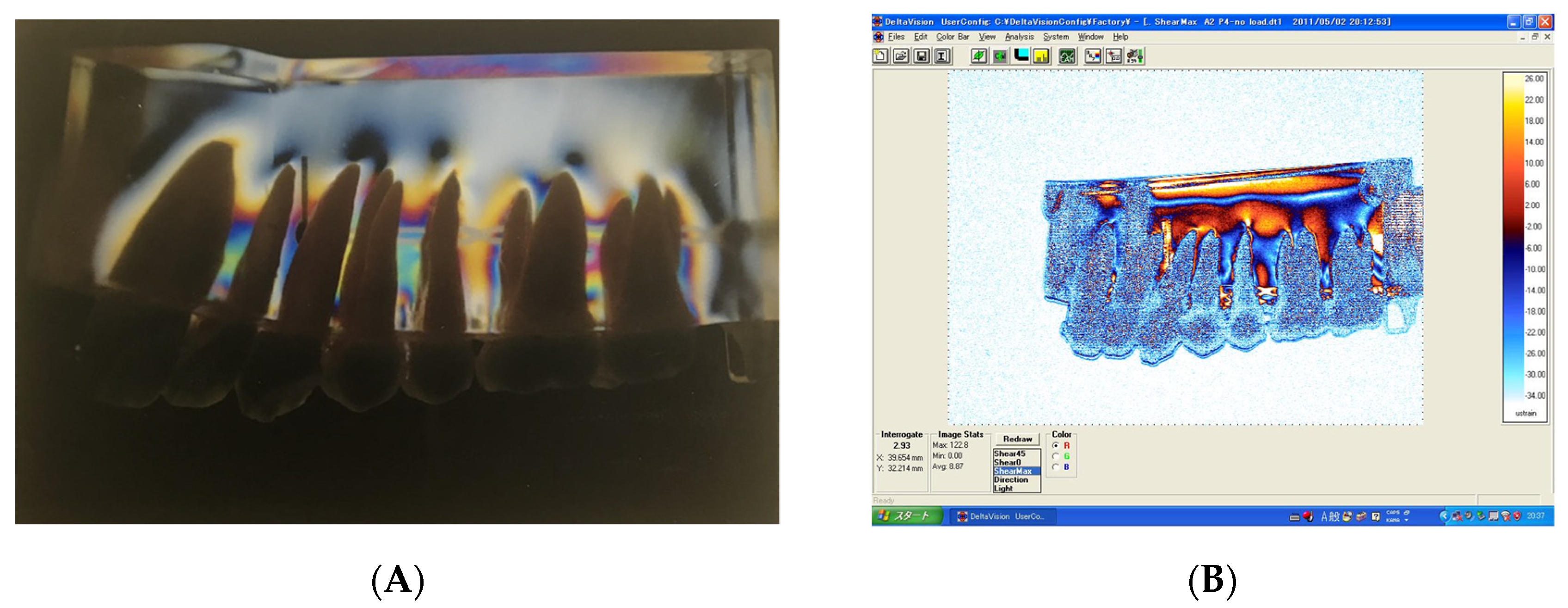
2.2. Measurement System

The stress distribution and strength measurement around the tooth roots were carried out with each combination (hook length and posterior anchor) using a digital photoelastic strain measurement system (GFT1400 Stress Photonics, Madison, WI, USA). In the conventional analog photoelastic method, the stress patterns that appear as fringes or bands of color are evaluated by visual observation (Figure 3A). However, the newer and superior digital photoelastic method can analyze these fringes quantitatively (Figure 3B). The system includes a set of software tools that are used to make measurements reliably and accurately.

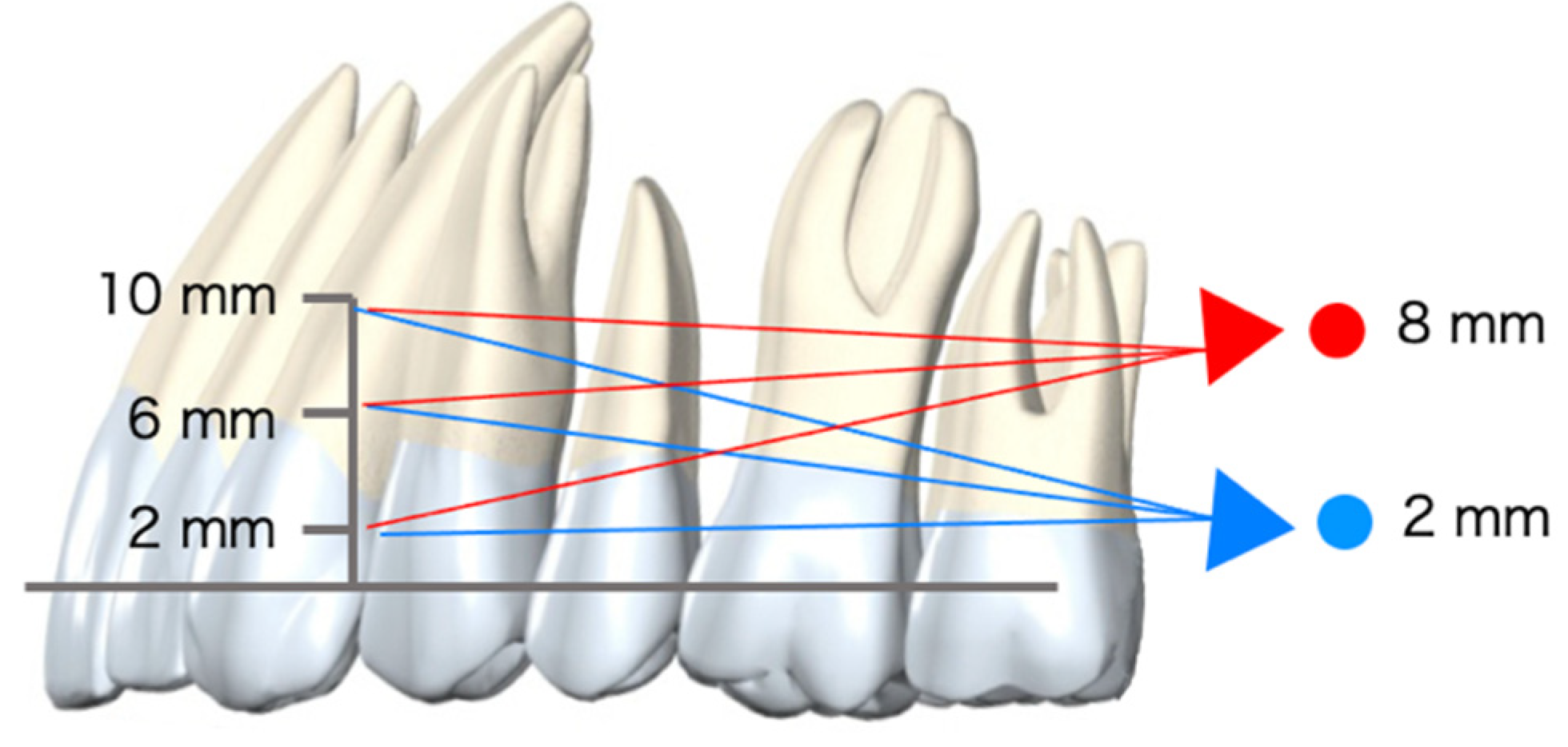
2.3. Measurement Categories

2.3.1. Stress Distribution and Strength

The method of measurement was by evaluating compressional and tensional stress using a different function (measurement of the model with and without applying the tension of the power chain to visualize the difference on computer software) to cancel the residual stress at the time of fabrication (which often interferes with accurate measurement) (Figure 3B). Tensional stress increases in the order of white, blue, then navy, and compressional stress increases in the order of orange, yellow, and white.

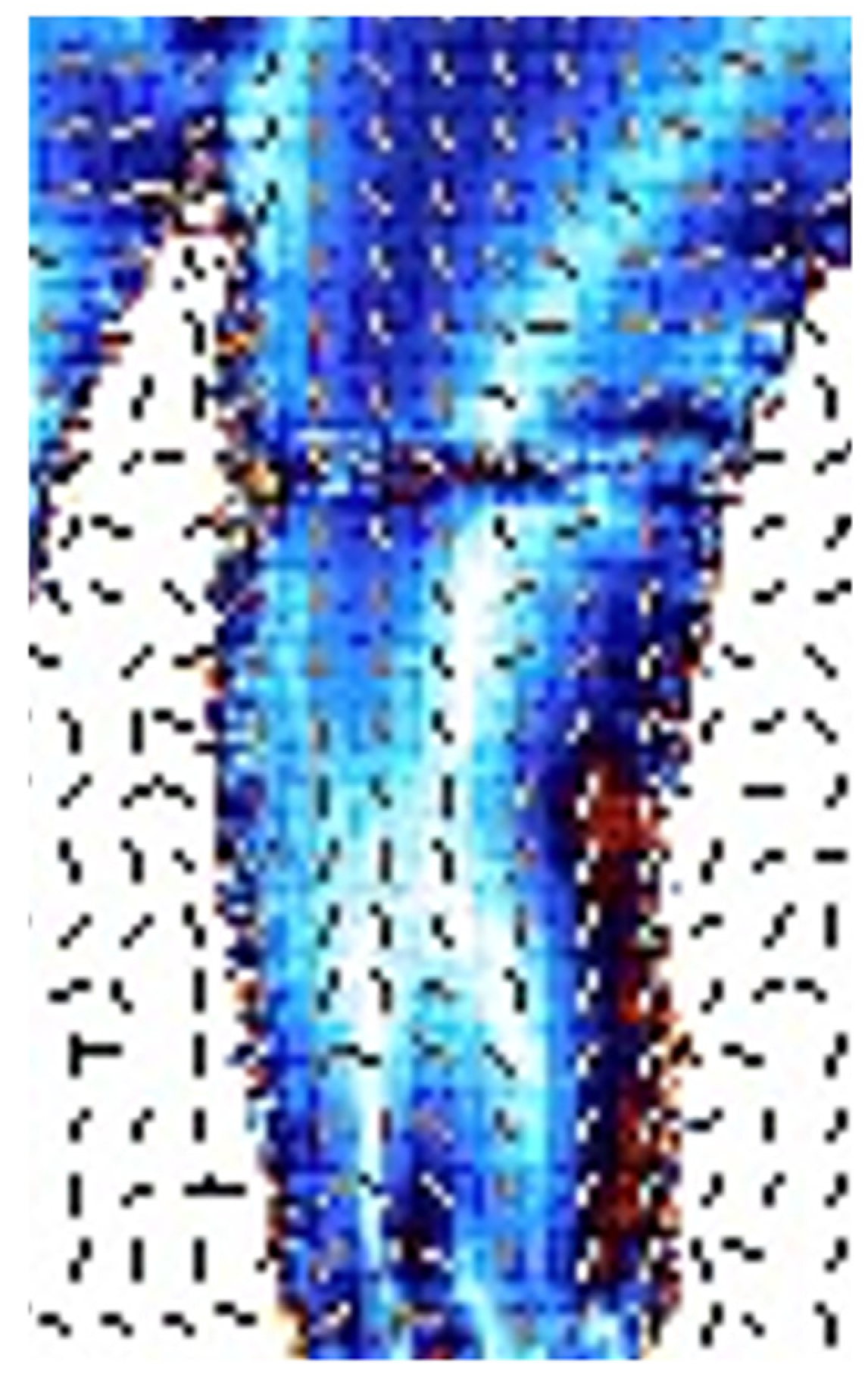
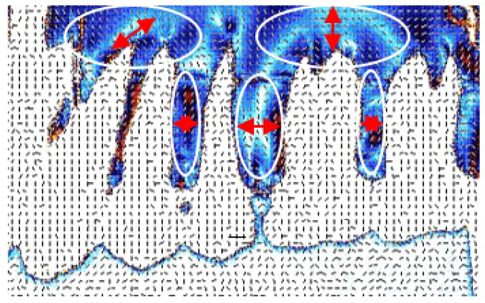
2.3.2. Stress Direction

The stress direction was detected by using the strain direction measurement function of the digital photoelastic strain measurement system. The stress direction was indicated by the vertical direction of each dash in the digital stress distribution image (Figure 4).

3. Results

Compressive and tensile stress was confirmed in the interarticular septum for all six combinations; however, the following characteristics were observed, depending on the length of the retraction hook and position of the posterior anchor. Compressive and tensile stress were colored from white to yellow depending on the degree. The stress distribution changed in each combination.

3.1. Stress Distribution and Strength (by Combinations)

3.1.1. Two-Millimeter Anchor Model

  • Two-millimeter-long retraction hook (Figure 5)
  • Apical region: Compressive stress was detected around the root apex of the overall dentition. However, tensile stress was observed at the apex of the incisor;
  • Center region: Compressive stress was observed in the cervical area of the distal root surface from the lateral incisor to the molars;
  • Cervical region: Tensile stress was observed in the cervical third of the mesial root surface of the second premolars.
  • Six-millimeter-long retraction hook (Figure 6)
(a)
Apical region: Similar tendencies to the 2 mm retraction hook were observed.
However, both the area and the strength of the compressive stress were remarkably decreased in the apical region;
(b)
Center region
Compressive stress area increased in the distal region of the second premolar;
(c)
Cervical region
Compared to the 2 mm retraction hook setting at the second premolar, compressive stress decreased.
  • Ten-millimeter-long retraction hook (Figure 7)
(a)
Apical region
Conversely to the 2 mm and 6 mm retraction hook sets, compressive stress vanished, and the tensile stress appeared in the apical region from the canine to the second molar. Additionally, compressive stress was detected at the apex of the central incisor;
(b)
Center region
Tensile stress was extended to the inter root space at the second premolar to the second molar at the center region;
(c)
Cervical region
The compressive stress was observed at the only cervical region in this setting.

3.1.2. Eight-Millimeter Anchor Model

  • Two-millimeter-long retraction hook (Figure 8)
(a)
Apical region
A compressive stress area was detected around the all roots apexes. It resembled the setting of the 2 mm posterior anchor with a 2 mm-long retraction hook; however, the compressive stress spread the most widely and strongly among all six settings at the apical region;
(b)
Center region
The compressive stress area expanded to the inter root space at the center region from the canine to the second molar.
(c)
Cervical region
Compressive stress was observed most widely in the cervical region.
  • Six-millimeter-long retraction hook (Figure 9)
(a)
Apical region
Compressive stress in the lateral segment of dentition was observed; however, the forces decreased compared to the 2 mm length of the retraction hook setting;
(b)
Center region
The compressive stress decreased at the center region;
(c)
Cervical region
Compressive stress was observed, but the degree was smaller than that of the 2 mm-long retraction hook setting.
  • Ten-millimeter-long retraction hook (Figure 10)
(a)
Apical region
Dark red and deep blue colors were observed at the apical region, which means that less compressive and tensile stress were applied to this region. The aspect was similar to the setting of a 6 mm posterior anchor with a 2 mm-long retraction hook;
(b)
Center region
A compressive stress region was observed at the distal region of the second premolar, the aspect is also similar to the setting of 6 mm posterior anchor with 2 mm-long retraction hook;
(c)
Cervical region
Compressive stress decreased.

3.2. Stress Direction

The stress direction was similar for all combinations of anchor position and hook length. In the apical area of the six anterior teeth, the stress direction was oblique. Between the premolar and molar roots, the stress direction was horizontal. In the apical region of the molars, the model showed that the direction of stress was vertical (Figure 11). A pattern emerged from anterior to posterior: oblique to horizontal to vertical.

4. Discussion

4.1. Overall Findings in the Context of the Experiment and Interpretation

In this study, we calculated the compressional, tensional stress, and stress direction around the tooth root during the distalization of maxillary dentition with a skeletal anchorage using the novel digital photoelastic method to improve our understanding of the movement of individual teeth, including the roots. The study mainly assumed a plate-type anchor [6,21], which can retract from any position in the vertical dimension, or a miniscrew implant anchor, whose placement position is limited by the inter root space [22,23], as the retraction position, and the height was adjusted accordingly. As a result, compressive stress was observed in the distal direction around the interarticular septum throughout the dentition for all six combinations of retraction hook lengths and posterior anchor positions. In addition, the stress direction and stress strength change were observed due to the difference between the length of the retraction hook and the position of the posterior anchor, especially in the apical region.

4.2. Biomechanics of Dentition

From the viewpoint of biomechanics, the moment of center of resistance (CR) in the maxillary dentition, the moment at the junction of the retraction hook and main arch, and the direction of retraction force should be considered during the distalization maxillary dentition (Figure 12). These factors work in a complex manner to determine the retraction condition for dentition. Kojima et al. [16] used a 3DFEM model to report that changes in moments occur to CR depending on the retraction hook length, TAD position, and changes in the movement patterns of anterior teeth. Their study showed similar stress distribution results. However, in their study, molar intrusion occurred when the tensile direction from the TAD was from the apex, whereas molar extrusion occurred when retracted from the cervical region. Hamanaka et al. [24] used a more sophisticated simulation of long-term orthodontic tooth movement in 3DFEM and reported that the lingual tipping of anterior teeth occurred during anterior retraction. These results are also consistent with our results. There are several reports on the location of CR in the maxillary dentition. In this study, since the stress at the second premolars differed significantly in the six models, CR in the maxillary dentition appeared in the cervical half or third of the distal root surface of the second premolars. Kojima et al. [16] performed a simulation of anterior maxillary retraction using a 3D finite element model. They reported that the CR on the distal root surface of the second premolar was 6.5–7 mm above the archwire. Our study is not 3DFEM, but these results support our experimental results.

4.3. Digital Photoelastic Method

3DFEM is considered to be the most helpful tool for mechanical analysis today, because 3DFEM can analyze complex stress behavior in three dimensions, initial tooth displacement in the periodontal ligament, and long-term orthodontic tooth movement [16,24,25,26]. Even such a versatile 3DFEM has its disadvantages: it is a simulation; therefore, the results depend on the conditions set by the researcher. The photoelastic method can only detect strain, without any artificial manipulation. Therefore, the results are very objective [27], as it is not a computer simulation. Moreover, the digital photoelastic method, which we used in this study, makes it possible to measure the detailed stress distributions, including tensile stress and compressive stress, which were impossible to determine using the conventional analog photoelastic method [17]. As future topics, analysis with the 3D digital photoelastic method [28] and 3DFEM method, as well as clinical verification or vice versa, are necessary to further verify the results of this and any other models that will ultimately aid clinicians.

4.4. Clinical Implications

The following clinical implications can be considered based on the stress distribution and direction analysis using digital photoelastic analysis in this study.
  • TAD positioned to retract from the cervical region
When a short hook is used, the crown is tipped distally during distal movement, and the molar will be intruded. However, with the middle hook, the vertical movement will be decreased. With the long hook, rotational movements in the anterior–superior direction were observed and applied molar downward direction, which increases the possibility of molar extrusion. Therefore, evaluating facial type in a clinical situation is crucial before selecting a hook length. This is due to the report [29] that, because the masticatory muscle activity is weak in high-angle facial types, resistance to molar extrusion is weak and mandibular rotation in the posterior-inferior direction and Class II relation could worsen as a consequence. Therefore, the short hook should be recommended for the high-angle case to distalize maxillary molars with the cervical position of TAD.
2.
TAD positioned to retract from the apex
In this situation, the molars tend to intrude while the dentition moves distally (Figure 13); therefore, it is presumed that this position is suitable for high-angle cases of Class II division 1. In addition, a long hook is considered advantageous to perform torque movement on lingually inclined maxillary anterior teeth, such as in Class II division 2.
In analyzing all combinations, the maxillary arch will be distalized parallel to the occlusal plane in the settings with the cervical position of TAD and medium hook, and the apical position of TAD and long hook.

5. Conclusions

  • Upward stress in molars and distal stress at the cervical region in the whole dentition were applied with a short hook regardless of the TAD position. This means that molar intrusion or posterior-superior occlusal plane rotation will occur.
  • Downward stress in molars and distal stress at the apical third of the canine were applied with the TAD in the cervical position, especially with a long hook. This means that molar extrusion or posterior-inferior occlusal plane rotation will occur.
  • Relatively uniform compressive stress was detected in the cervical position of TAD with a medium hook and apical position of TAD with a long hook. This means that the maxillary arch will be distalized parallelly to the occlusal plane.
  • The digital photoelastic analysis method has great potential for evaluating orthodontic biomechanics.

Author Contributions

Conceptualization, methodology, writing, and supervision, Y.N.; writing—review and editing, G.T.S.; data curation and writing—review and editing, C.T. All authors have read and agreed to the published version of the manuscript.

Funding

This research received no external funding.

Institutional Review Board Statement

Not applicable.

Data Availability Statement

Not applicable.

Acknowledgments

The authors are grateful to Masataka Kano for fabricating photoelastic model with dentition. We also thank Tamae Usuda for the measurement dataset of the photoelastic model.

Conflicts of Interest

The authors declare no conflict of interest.

References

  1. Ghosh, J.N.R. Evaluation of an intraoral maxillary molar distalization technique. Am. J. Orthod. Dentofac. Orthop. 1996, 110, 639–946. [Google Scholar] [CrossRef]
  2. Kinzinger, G.S.M.; Eren, M.; Diedrich, P.R. Treatment effects of intraoral appliances with conventional anchorage designs for non-compliance maxillary molar distalization. A literature review. Eur. J. Orthod. 2008, 30, 558–571. [Google Scholar] [CrossRef] [PubMed] [Green Version]
  3. Antonarakis, G.S.; Kiliaridis, S. Maxillary molar distalization with noncompliance intramaxillary appliances in class II malocclusion: A systematic review. Angle Orthod. 2008, 78, 1133–1140. [Google Scholar] [CrossRef] [PubMed] [Green Version]
  4. Jambi, S.; Thiruvenkatachari, B.; O’Brien, K.D.; Walsh, T. Orthodontic treatment for distalising upper first molars in children and adolescents. Cochrane Database Syst. Rev. 2013, 2013, CD008375. [Google Scholar] [CrossRef]
  5. Al-Thomali, Y.; Basha, S.; Mohamed, R.N. Pendulum and modified pendulum appliances for maxillary molar distalization in Class II malocclusion—A systematic review. Acta Odontol. Scand. 2017, 75, 394–401. Available online: https://www.tandfonline.com/doi/full/10.1080/00016357.2017.1324636 (accessed on 15 December 2021). [CrossRef]
  6. Sugawara, J.; Kanzaki, R.; Takahashi, I.; Nagasaka, H.; Nanda, R. Distal movement of maxillary molars in nongrowing patients with the skeletal anchorage system. Am. J. Orthod. Dentofac. Orthop. 2006, 129, 723–733. [Google Scholar] [CrossRef]
  7. Cornelis, M.A.; De Clerck, H.J. Maxillary molar distalization with miniplates assessed on digital models: A prospective clinical trial. Am. J. Orthod. Dentofac. Orthop. 2007, 132, 373–377. [Google Scholar] [CrossRef]
  8. Papadopoulos, M.A.; Tarawneh, F. The use of miniscrew implants for temporary skeletal anchorage in orthodontics: A comprehensive review. Oral Surg. Oral Med. Oral Pathol. Oral Radiol. Endodontol. 2007, 103, 6–15. [Google Scholar] [CrossRef]
  9. Fudalej, P.; Antoszewska, J. Are orthodontic distalizers reinforced with the temporary skeletal anchorage devices effective? Am. J. Orthod. Dentofac. Orthop. 2011, 139, 722–729. [Google Scholar] [CrossRef]
  10. Konno, M.; Uechi, J.; Tsuji, Y.; Shibata, T.; Mizoguchi, I. Three-dimensional Morphological Analysis of Dental Compensation in Facial Asymmetry Cases. Jpn. J. Jaw Deform 2014, 24, 37–45. Available online: http://jlc.jst.go.jp/DN/JST.JSTAGE/jjjd/24.37?lang=en&from=CrossRef&type=abstract (accessed on 15 December 2021). [CrossRef] [Green Version]
  11. Ook, Y.-A.; Bayome, M.; Trang, V.T.T.; Kim, H.-J.; Park, J.H.; Kim, K.B.; Behrents, R.G. Treatment effects of a modified palatal anchorage plate for distalization evaluated with cone-beam computed tomography. Am. J. Orthod. Dentofac. Orthop. 2014, 146, 47–54. [Google Scholar] [CrossRef]
  12. Roberts, W.E.; Viecilli, R.F.; Chang, C.; Katona, T.R.; Paydar, N.H. Biology of biomechanics: Finite element analysis of a statically determinate system to rotate the occlusal plane for correction of a skeletal Class III open-bite malocclusion. Am. J. Orthod. Dentofac. Orthop. 2015, 148, 943–955. [Google Scholar] [CrossRef] [PubMed] [Green Version]
  13. Duran, G.S.; Görgülü, S.; Dindaroğlu, F. Three-dimensional analysis of tooth movements after palatal miniscrew-supported molar distalization. Am. J. Orthod. Dentofac. Orthop. 2016, 150, 188–197. [Google Scholar] [CrossRef] [PubMed] [Green Version]
  14. Nakamura, M.; Kawanabe, N.; Kataoka, T.; Murakami, T.; Yamashiro, T.; Kamioka, H. Comparative evaluation of treatment outcomes between temporary anchorage devices and Class III elastics in Class III malocclusions. Am. J. Orthod. Dentofac. Orthop. 2017, 151, 1116–1124. [Google Scholar] [CrossRef] [PubMed]
  15. Nakamura, A.; Teratani, T.; Itoh, H.; Sugawara, J.; Ishikawa, H. Photoelastic stress analysis of mandibular molars moved distally with the skeletal anchorage system. Am. J. Orthod. Dentofac. Orthop. 2007, 132, 624–629. [Google Scholar] [CrossRef]
  16. Kojima, Y.; Kawamura, J.; Fukui, H. Finite element analysis of the effect of force directions on tooth movement in extraction space closure with miniscrew sliding mechanics. Am. J. Orthod. Dentofac. Orthop. 2012, 142, 501–508. [Google Scholar] [CrossRef]
  17. Carvalho, L.; Roriz, P.; Simões, J.; Frazão, O. New Trends in Dental Biomechanics with Photonics Technologies. Appl. Sci. 2015, 5, 1350–1378. [Google Scholar] [CrossRef] [Green Version]
  18. Knop, L.; Gandini Jr, L.G.; Shintcovsk, R.L.; Gandini, M.R.E.A.S. Scientific use of the finite element method in Orthodontics. Dent. Press J. Orthod. 2015, 20, 119–125. Available online: http://www.scielo.br/scielo.php?script=sci_arttext&pid=S2176-94512015000200119&lng=en&tlng=en (accessed on 15 December 2021). [CrossRef]
  19. Sakurai, Y.; Nishii, Y.; Kodaka, K.; Nojima, K.; Sueishi, K. Crown angulation measured by laser scanner. Orthod. Waves 2010, 69, 13–17. [Google Scholar] [CrossRef]
  20. Kodaka, K.; Nishii, Y.; Sakurai, Y.; Nojima, K.; Sueishi, K. Crown inclination measured by laser scanner. Orthod. Waves 2010, 69, 8–12. [Google Scholar] [CrossRef]
  21. Sugawara, J.; Daimaruya, T.; Umemori, M.; Nagasaka, H.; Takahashi, I.; Kawamura, H.; Mitani, H. Distal movement of mandibular molars in adult patients with the skeletal anchorage system. Am. J. Orthod. Dentofac. Orthop. 2004, 125, 130–138. [Google Scholar] [CrossRef] [PubMed]
  22. Alsamak, S.; Gkantidis, N.; Bitsanis, E.; Christou, P. Assessment of Potential Orthodontic Mini-implant Insertion Sites Based on Anatomical Hard Tissue Parameters: A Systematic Review. Int. J. Oral Maxillofac. Implants 2012, 27, 875–887. [Google Scholar] [PubMed]
  23. Alsamak, S.; Psomiadis, S.; Gkantidis, N. Positional Guidelines for Orthodontic Mini-implant Placement in the Anterior Alveolar Region: A Systematic Review. Int. J. Oral Maxillofac. Implant. 2013, 28, 470–479. Available online: http://www.quintpub.com/journals/omi/abstract.php?iss2_id=1108&article_id=13009&article=25&title=Positional Guidelines for Orthodontic Mini-implant Placement in the Anterior Alveolar Region: A Systematic Review (accessed on 15 December 2021). [CrossRef] [PubMed] [Green Version]
  24. Hamanaka, R.; Yamaoka, S.; Anh, T.N.; Tominaga, J.-Y.; Koga, Y.; Yoshida, N. Numeric simulation model for long-term orthodontic tooth movement with contact boundary conditions using the finite element method. Am. J. Orthod. Dentofac. Orthop. 2017, 152, 601–612. [Google Scholar] [CrossRef]
  25. Alrbata, R.H.; Yu, W.; Kyung, H.-M. Biomechanical effectiveness of cortical bone thickness on orthodontic microimplant stability: An evaluation based on the load share between cortical and cancellous bone. Am. J. Orthod. Dentofac. Orthop. 2014, 146, 175–182. [Google Scholar] [CrossRef]
  26. Tominaga, J.-Y.; Ozaki, H.; Chiang, P.-C.; Sumi, M.; Tanaka, M.; Koga, Y.; Bourauel, C.; Yoshida, N. Effect of bracket slot and archwire dimensions on anterior tooth movement during space closure in sliding mechanics: A 3-dimensional finite element study. Am. J. Orthod. Dentofac. Orthop. 2014, 146, 166–174. [Google Scholar] [CrossRef]
  27. Pinit, P.; Umezaki, E. Full-Field Determination of Principal-Stress Directions Using Photoelasticity with Plane-Polarized RGB Lights. Opt. Rev. 2005, 12, 228–232. [Google Scholar] [CrossRef]
  28. Umezaki, E. Stress Distribution Measurement Techniques Using Photoelasticity: Current Status and Future Prospects. J. Jpn. Soc. Precis. Eng. 2013, 79, 607–611. [Google Scholar] [CrossRef] [Green Version]
  29. Ueda, H.M.; Miyamoto, K.; Ishizuka, Y.; Tanne, K. Masticatory muscle activity in children and adults with different facial types. Am. J. Orthod. Dentofac. Orthop. 2000, 118, 63–68. [Google Scholar] [CrossRef]
Figure 1. A photoelastic model consisting of a bracket, archwire, alveolar bone made of epoxy resin, retraction hook, posterior anchor, and elastic for applying retraction force.
Applsci 12 01949 g001
Figure 2. Six combinations with three retraction hook lengths (2 mm, 6 mm, and 10 mm) and two posterior anchor positions (2 mm and 8 mm from the maxillary first molar cervical region).
Applsci 12 01949 g002
Figure 3. (A) Analog photoelastic model with the stress patterns appearing as fringes or bands of color. (B) Digital photoelastic analyzing image on a PC screen with stress distribution appearing by digital processing.
Applsci 12 01949 g003
Figure 4. Stress direction analyzing image indicating the stress direction as vertical to each dash. The blue area shows photoelastic resin and white area shows tooth root.
Applsci 12 01949 g004
Figure 5. Two-millimeter retraction hook and 2 mm positioned posterior anchor model.
Applsci 12 01949 g005
Figure 6. Six-millimeter retraction hook and 2 mm positioned posterior anchor model.
Applsci 12 01949 g006
Figure 7. Ten-millimeter retraction hook and 2 mm positioned posterior anchor model.
Applsci 12 01949 g007
Figure 8. Two-millimeter retraction hook and 8 mm positioned posterior anchor mode.
Applsci 12 01949 g008
Figure 9. Six-millimeter retraction hook and 8 mm positioned posterior anchor model.
Applsci 12 01949 g009
Figure 10. Ten-millimeter retraction hook and 8 mm positioned posterior anchor model.
Applsci 12 01949 g010
Figure 11. The average tendency of the stress direction in all six combinations. The stress direction of all combinations showed the same tendency, as follows: oblique in the anterior teeth root apex, horizontal at inter root space between the premolars and molars, and vertical in the apical area of the molars.
Applsci 12 01949 g011
Figure 12. Supposed two centers of rotation; each CR functions in the opposite direction. CR1: the center of rotation of dentition, which is assumed to be positioned at the cervical half or third of the distal root surface of the second premolars; CR2: the center of rotation of the junction of the main arch and hook.
Applsci 12 01949 g012
Figure 13. The second premolar and first molar have been intruded during retraction with TAD positioned at the apical region.
Applsci 12 01949 g013
Publisher’s Note: MDPI stays neutral with regard to jurisdictional claims in published maps and institutional affiliations.

