Article

Algorithm for an Effective Ratio of the Transverse Bending Rigidity Based on the Segment Joint Bending Stiffness

1
Engineering Research Center of Railway Environmental Vibration and Noise, Ministry of Education, East China Jiaotong University, Nanchang 330013, China
2
State Key Laboratory of Performance Monitoring and Protecting of Rail Transit Infrastructure, East China Jiaotong University, Nanchang 330013, China
3
College of Civil and Transportation Engineering, Shenzhen University, Shenzhen 518000, China
*
Author to whom correspondence should be addressed.
Appl. Sci. 2022, 12(4), 1901; https://doi.org/10.3390/app12041901
Submission received: 15 January 2022 / Revised: 8 February 2022 / Accepted: 10 February 2022 / Published: 11 February 2022
(This article belongs to the Special Issue Deep Rock Mass Engineering: Excavation, Monitoring, and Control)

Abstract

:
An algorithm for calculating the effective ratio of the transverse bending rigidity is established based on the segment longitudinal joint bending stiffness. With the knowledge of this effective ratio, the bending rigidity of a modified uniform rigidity ring is fully defined. To verify this developed algorithm, the effective ratios and convergence deformations of the modified uniform rigidity rings obtained with different methods are compared. Moreover, the responses of the modified uniform rigidity ring model under loading obtained from this algorithm are compared to those obtained with the existing generally accepted beam-spring model. The results show that although the bending moments obtained from these two models are different, the axial forces, horizontal convergent deformations, and vertical convergent deformations are quite consistent with each other. The modified uniform rigidity ring model built on the developed effective ratio algorithm is applicable for the analysis of the tunnel convergence deformation and the interaction between the tunnel structure and the ground during operation. This modified uniform rigidity ring model is simpler and easier to use than the beam-spring model; thus, the significance of the developed algorithm for the effective ratio of the transverse bending rigidity is demonstrated.

1. Introduction

Many segment ring models, such as the uniform rigidity ring model [1], modified uniform rigidity ring model [2], multi-hinge ring model [3,4], beam-spring model [5,6,7], beam-discontinuous joint model [8], and shell-spring model [9], are used for the transverse analysis of the internal force and deformation of shield-driven tunnels. The main difference between all these models is the way that the flexural behavior of the longitudinal joints is considered. Indeed, the way to address the segment longitudinal joint is critical for the analysis of the shield tunnel structure [10,11,12,13].
At present, the more popular methods for the analysis of the tunnel structure are the beam-spring model and modified uniform rigidity ring model. The beam-spring model, which involves the longitudinal joint bending stiffness as the key parameter, behaves close to the actual state of the installed segment ring [14,15]. The existing research regarding the beam-spring model mainly concentrates on the factors affecting the longitudinal joint bending stiffness and how the longitudinal joint bending stiffness affects the internal force and deformation [3,16,17,18,19]. Because of the limitations of all these methods, deviations among these studies are expected.
Moreover, it is difficult to establish the beam-spring model in the numerical simulation, and the application of the beam-spring model is relatively complex. For the beam-spring model, longitudinal joints are treated as three-dimensional springs with flexural stiffness, axial stiffness, and shearing stiffness. In contrast, for the modified uniform rigidity ring model, the longitudinal joints of the installed segment ring are neglected. However, the effect of the longitudinal joints is still considered in the modified uniform rigidity ring model by reducing the transverse bending rigidity of a uniform rigidity ring. Thus, the bending rigidity of the modified uniform rigidity ring model can be obtained by multiplying the bending rigidity of the transverse section of the segment by the effective ratio of the transverse bending rigidity η . Compared to the generally accepted but more comprehensive beam-spring model, the modified uniform rigidity ring model is simpler and easier to use. However, as the key parameter of the modified uniform rigidity ring model, the value of η is difficult to determine [2,20,21].
Many studies have focused on the methods of how to obtain the value of η [20,22,23,24,25], and the factors influencing η [4,24,25,26] have been reported. The existing methods to determine η are often too complex or lack a theoretical basis, and empirical equations based on model tests [27] are unable to correctly characterize the correlation between η and its influencing factors, such as the longitudinal joint bending stiffness, the diameter of the segment ring, the thickness of the segment, and the number of joints [28].
In this article, the correlation between the longitudinal joint bending stiffness of an installed segment ring and the effective ratio of the transverse bending rigidity of a modified uniform rigidity ring is investigated. Then, formulas that express the correlation between the effective ratio of the transverse bending rigidity and its influencing factors are derived according to the longitudinal joint bending stiffness. With the knowledge of this effective ratio, the bending rigidity of a modified uniform rigidity ring is fully defined. Finally, the validity of the established algorithm for calculating the effective ratio of the transverse bending rigidity is verified by comparing the responses of the tunnel rings using the modified uniform rigidity ring models, which are established according to the effective ratio obtained by different methods, with those obtained with the generally accepted but more complex beam-spring model.

2. Algorithm of the Effective Ratio of the Transverse Bending Rigidity

2.1. Equivalent Equation of Transverse Bending Rigidity

Because the bending rigidity of each section of the modified uniform rigidity ring is the same, reducing the transverse bending rigidity of a uniform rigidity ring with the same geometric dimensions of the installed segment ring can be accomplished by evenly allocating the weakness caused by longitudinal joints of the installed segment ring to all of the sections of the modified uniform rigidity ring. Thus, the equivalence of the transverse bending performance between the modified uniform rigidity ring and the installed segment ring is often a necessity. To calculate the effective ratio of the transverse bending rigidity based on the longitudinal joint bending stiffness of the installed segment ring, several assumptions are made as follows: (1) the installed segment ring and modified uniform rigidity ring are spread into straight beams by cutting them apart at the bottom position (at the position of 180°), as shown in Figure 1; (2) the condition that the end sections of both straight beams have the same relative rotation angle under the same pure bending moment is regarded as the equivalent condition of the transverse bending rigidity for both rings; and (3) when the equivalent condition of the transverse bending rigidity is satisfied, the ratio that the bending rigidity of the transverse section of a modified uniform rigidity ring to that of the corresponding installed segment ring is termed the effective ratio of the transverse bending rigidity η . Spread straight beams from the installed segment ring and the modified uniform rigidity ring and their corresponding geometric dimensions are shown in Figure 1. The installed segment ring shown in Figure 1 is the tunnel lining of a shield-driven tunnel with non-staggered installation, which is widely used in Shanghai’s single-line metro.
The mean value of the outer and inner circumferences of the installed segment ring is taken as the length of its spread straight beam. It can be calculated using Equation (1):
L = ( D 1 + D 2 ) 2 π
where L is the length of the straight beam spread from the installed segment ring, D 1 is the outer diameter of the installed segment ring, and   D 2 is the inner diameter of the installed segment ring.
According to Hooke’s law, the elastic flexural strain of a straight beam is given by Equation (2), when subjected to the pure bending moment M :
κ = M E I
where κ is the flexural strain, which is defined as the rotation angle developed per unit length; M is the pure bending moment acting on the ends of the spread straight beam;   E I is the bending rigidity of the transverse section of the segment; E is the elastic modulus of the segment; and I is the moment of inertia for the transverse section of the segment.
Without considering the rotation angles of all joints, the relative rotation angle for the end sections of the straight beam spread from the installed segment ring may be expressed as Equation (3), when subjected to the pure bending moment M :
θ 1 = L M E I
where θ 1 is the relative rotation angle for the end sections of the straight beam spread from the installed segment ring, which is caused by the bend of the beam.
However, the bending rigidity of the spread straight beam is weakened by the existence of segment longitudinal joints. When the joint is subjected to the pure bending moment, the rotation angle of the joint can be expressed as Equation (4):
Δ θ = M k
where Δ θ is the rotation angle of the joint and k is the bending stiffness of the segment longitudinal joint.
For the installed segment ring used in the Shanghai metro (as shown in Figure 1), there are six joints on its straight beam: the number of joints with a bending stiffness of k 1 , k 2 , or k 3 is two. The summation of the rotation angles of all the joints on the spread straight beam under the pure bending moment M can be expressed as Equation (5). Accordingly, under the pure bending moment M , the relative rotation angle for the end sections of the straight beam spread from the installed segment ring can be calculated by Equation (6):
θ 2 = 2 ( M k 1 + M k 2 + M k 3 )
θ = θ 1 + θ 2 = L M E I + 2 ( M k 1 + M k 2 + M k 3 )
where θ 2 is the summation of the rotation angles of all the joints on the straight beam, which is spread from the installed segment ring; k i is the longitudinal joint bending stiffness for joint i; and θ is the relative rotation angle for the end sections of the straight beam, which is spread from the installed segment ring.
The bending rigidity of the transverse section of the modified uniform rigidity ring is assumed to be E I . Under the pure bending moment, the relative rotation angle of the end sections of the straight beam spread from the modified uniform rigidity ring can be expressed as Equation (7):
θ = L M E I
where θ is the relative rotation angle of the end sections of the straight beam, which is spread from the modified uniform rigidity ring; L is the length of the straight beam spread from the modified uniform rigidity ring; E I is the bending rigidity of the transverse section of the modified uniform rigidity ring; E   is the elastic modulus of the modified uniform rigidity ring; and I is the moment of inertia for the transverse section of the modified uniform rigidity ring.
According to the equivalent condition of the transverse bending rigidity, Equation (8) can be derived and simplified into Equation (9), which is denoted as the equivalent equation of the transverse bending rigidity:
L M E I = L M E I + 2 ( M k 1 + M k 2 + M k 3 )
L E I = L E I + 2 k 1 + 2 k 2 + 2 k 3

2.2. Reduction of Bending Rigidity by Reducing the Elastic Modulus

To satisfy the equivalent condition of the transverse bending rigidity between an installed segment ring and a modified uniform rigidity ring, the elastic modulus E or the moment of inertia I should be reduced accordingly [29]. When E is reduced, the geometric dimensions of the modified uniform rigidity ring and the installed segment ring are the same, namely, I = I , L = L . Thus, Equation (10) can be obtained from Equation (9), and E can be expressed as Equation (11):
L E I = L E I + 2 k 1 + 2 k 2 + 2 k 3
E = E L L + 2 E I ( 1 k 1 + 1 k 2 + 1 k 3 )
According to the definition of the effective ratio of the transverse bending rigidity η for the modified uniform rigidity ring (i.e., η = E I / E I ), η can be expressed as Equation (12):
η = E E = L L + 2 E I ( 1 k 1 + 1 k 2 + 1 k 3 )
where η is the effective ratio of the transverse bending rigidity for the modified uniform rigidity ring.

2.3. Reduction of Bending Rigidity by Reducing the Moment of Inertia

There are two methods to reduce the moment of inertia; both achieve this goal by reducing the thickness based on a uniform rigidity ring with the same geometric dimensions of the installed segment ring. The first method is to increase the inner diameter and to decrease the outer diameter of the uniform rigidity ring simultaneously (the amount of increase is set to be equal to the amount of decrease). The second method is to increase only the inner diameter of the uniform rigidity ring, causing the outer diameter of the modified uniform rigidity ring and that of the installed segment ring to be the same.
(1)
The first method of reducing the moment of inertia.
For the first method of reducing the moment of inertia, the length of the straight beams spread from the modified uniform rigidity ring and the installed segment ring is set to be equal (i.e., L = L ). According to Equation (9), the moment of inertia for the modified uniform rigidity ring can be expressed as Equation (13), and the effective ratio of the transverse bending rigidity can be expressed as Equation (14):
I = E L L I + 2 E k 1 + 2 E k 2 + 2 E k 3
η = I I = L L + 2 E I ( 1 k 1 + 1 k 2 + 1 k 3 )
It is noted that Equations (12) and (14) are the same.
If the number of joints for the installed segment ring is n , then the effective ratio of the transverse bending rigidity for the corresponding modified uniform rigidity ring can be expressed as Equation (15):
η = L L + E I i = 1 n 1 k i = ( D 1 + D 2 ) π ( D 1 + D 2 ) π + 2 E I i = 1 n 1 k i
where n is the number of joints for the installed segment ring and i = 1 n 1 k i is the summation of all the rotation angles of the joint on the installed segment ring under a unit bending moment.
If the other parameters in Equation (15) are kept constant, more joints on the installed segment ring and a larger section bending stiffness will lead to a smaller effective ratio of the transverse bending rigidity while a larger diameter of the segment ring and a larger joint bending stiffness correspond to a larger effective ratio of the transverse bending rigidity.
To reduce I , the thickness of the uniform rigidity ring is reduced, and the longitudinal width of the uniform rigidity ring is kept unchanged (i.e., b = b ). According to the equation that E I = η E I , Equation (16) can be derived, and the thickness of the modified uniform rigidity ring can be calculated by using Equation (17), because E = E :
E b h 3 12 = η E b h 3 12
h = η 3 h
where b is the longitudinal width of the modified uniform rigidity ring, h   is the thickness of the modified uniform rigidity ring, b is the longitudinal width of the installed segment ring, h is the thickness of the segment, and η 3 is the thickness reduction coefficient for a modified uniform rigidity ring.
If the installed segment ring shown in Figure 1 is converted into a corresponding modified uniform rigidity ring, the thickness reduction coefficient can be expressed as Equation (18) based on Equation (14):
α = η 3 = L L + 2 E I ( 1 k 1 + 1 k 2 + 1 k 3 ) 3 = ( D 1 + D 2 ) π ( D 1 + D 2 ) π + 2 E I i = 1 n 1 k i 3
where α is the thickness reduction coefficient for the modified uniform rigidity ring converted from the installed segment ring.
(2)
The second method of reducing the moment of inertia.
For the second method of reducing the moment of inertia, the length of the straight beam spread from the modified uniform rigidity ring can be calculated using Equation (19):
L = ( D 1 + D 2 2 ) π
If Equation (19) is substituted into Equation (9), Equation (20) can be derived:
L E I + 2 k 1 + 2 k 2 + 2 k 3 = ( D + D ) π 2 E I
Because E = E , Equation (21) can be obtained from Equation (20):
b 12 ( L I + 2 E ( 1 k 1 + 1 k 2 + 1 k 3 ) ) h 3 + π h π D = 0
As a cubic equation about the thickness of a modified uniform rigidity ring, Equation (21) has no quadratic term and has only one real root.

3. Verification of the Algorithm

3.1. Verification Sample

The sample of the installed segment ring used for the verification study is the tunnel lining of shield tunnels with non-staggered installation, which is widely used in Shanghai’s single-line metro. The outer diameter of the segment ring is 6.2 m, and the thickness and width of the segment are 0.35 and 1.2 m, respectively. The segment is precasted using high-strength concrete (C55 grade) of which the Poisson’s ratio and elastic modulus are 0.18 and 35.5 GPa, respectively. The segment ring is composed of six segments, which is shown in Figure 2. Straight bolts with a mechanical property grade of 5.8 are adopted for the circumferential and longitudinal connection of the segment rings.
To obtain the longitudinal joint bending stiffness of the installed segment ring, a back analysis of a full-scale test simulating the interaction between the load and structure was conducted [30]. To simulate the surrounding earth pressure, there are 24 loading points spaced evenly around the segment ring. All the loads are divided into 3 groups: P 1 (6 loading points), P 2 (10 loading points), and P 3 (8 loading points), which are also shown in Figure 2. Deformations measured in the full-scale test under four different loading conditions are used as a basis for the back analysis and are listed in Table 1. It is noted that the sign conventions adopted herein are positive for the outward deformations.
The beam-spring model [14,15], well recognized for its ability to simulate an installed segment ring accurately, is established here in a cylindrical coordinate system using ANSYS. A typical configuration includes 366 node elements, 360 curved beam elements, and 6 spring elements. Because of the symmetrical conditions, the bending stiffness of the segment longitudinal joints are k 1 at the positions of 8° and 352°, k 2 at the positions of 73° and 287°, and k 3   at the positions of 138° and 222°. Additionally, the horizontal and vertical restraints are applied at the 0° and 180° positions and at the 90° and 270° positions, respectively, which are shown in Figure 3. Values for the longitudinal joint bending stiffness obtained from the back analysis under different loading conditions are listed in Table 2.

3.2. Values of the Effective Ratio for the Transverse Bending Rigidity Based on the Full-Scale Test

As shown in Table 3, under the condition that L = L , including cases for reducing the bending rigidity by the reduction of E and reducing I by the first method of thickness reduction, the effective ratios of the transverse bending rigidity for a modified uniform rigidity ring can be calculated using Equation (12) or (14). Using the first method of thickness reduction, the thickness reduction coefficients can be calculated with Equation (18).
Under the condition that L > L , which represents the second method of thickness reduction, the thickness of a modified uniform rigidity ring can be obtained by solving Equation (21). As listed in Table 3, the thickness reduction coefficients and the corresponding effective ratios of the transverse bending rigidity for the modified uniform rigidity rings under different loading conditions can be obtained according to Equation (17). It is noted that the effective ratios and thickness reduction coefficients under the condition of L > L are slightly larger than those under the condition of L = L .
However, Yukinori [20] and Ye [24] proposed other methods to calculate the effective ratio of the transverse bending rigidity for the modified uniform rigidity ring, which can be expressed as Equations (22) and (23), respectively:
η 1 = D 1 + Δ D h u D 1 + Δ D h i  
η 2 = Δ D h u Δ D h i
where η 1 is the algorithm of Yukinori about the effective ratio of the transverse bending rigidity for the modified uniform rigidity ring, Δ D h u   is the horizontal convergence deformation of the uniform rigidity ring, Δ D h i is the horizontal convergence deformation of the installed segment ring, and η 2 is the algorithm of Ye about the effective ratio of the transverse bending rigidity for the modified uniform rigidity ring.
In order to use the method proposed by Yukinori and Ye to calculate the effective ratio, the convergence-confinement method is used to obtain the convergence deformation of the uniform stiffness ring and installed segment ring under different load conditions [31], which are represented by the uniform stiffness ring model and beam-spring model, respectively. These deformations are listed in Table 4. In engineering practice, the relative deformation at the positions of 90° and 270° is regarded as the horizontal convergence deformation while the deformation at 0° and 180° is regarded as the vertical convergence deformation. Therefore, effective ratios calculated with Equations (22) and (23) are obtained, which are listed in Table 5. It is noted that the effective ratios in Table 3 under the condition of L = L and those in Table 5, which are calculated with Equation (22), are extremely similar. However, the effective ratios in Table 5, which are calculated with Equation (23), are larger than those calculated with Equation (22) and those listed in Table 3.

3.3. Verification Analysis

To verify the algorithm proposed in this article, the modified uniform rigidity ring models are established according to the effective ratios of the transverse bending rigidity obtained by the methods proposed in this article (i.e., E < E and I = I ), by Yukinori and Ye, and simulated in a way similar to that of the beam-spring model established in the back analysis. Under the loads (at the 1st, 2nd, 3rd, and 4th loading conditions) applied in the full-scale test, the convergence deformations of the modified uniform rigidity rings are listed in Table 6. It is noted that under different loading conditions, the convergence deformations of the uniform rigidity rings obtained using the methods proposed in this article are extremely similar to those of the uniform rigidity rings obtained using Ye’s method [24] and are also similar to those of the installed segment rings shown in Table 4. On the other hand, the convergence deformations of the modified uniform rigidity rings established using the method proposed by Yukinori [20] are visibly different from other modified uniform rigidity rings.
Under the same loading condition, the interactions between the tunnel rings embedded in the ground and the surrounding earth can be similar only if the convergence deformations of a modified uniform rigidity ring are similar to those of an installed segment ring. Thus, the extent of the closeness between the convergence deformations of a modified uniform rigidity ring and those of the corresponding installed segment ring can be used to decide whether the effective ratio of the transverse bending rigidity is appropriate. Based on that decision, the methods for calculating the effective ratios proposed by Ye and developed in this article are feasible. Compared to the existing methods for obtaining the effective ratio of the transverse bending rigidity, the algorithm proposed in this article is simpler and more conceptually elegant. Moreover, the algorithm proposed in this article has established the correlation between the longitudinal joint bending stiffness (i.e., the key parameter of the installed segment ring) and the effective ratio (i.e., the decisive parameter of the modified uniform rigidity ring). Additionally, the algorithm can express the correlation between the effective ratio and other influencing factors, such as the diameter of the tunnel ring [32], thickness of the segment [33], and number of joints [34], and this algorithm is easier to use than the existing methods.
To discuss the difference between the beam-spring model and the modified uniform rigidity ring model developed in this article, the deformations, bending moments, and internal forces of both models under different loading conditions are compared in Figure 4, Figure 5 and Figure 6. The simulated results under different loading conditions are shown in Table 7, Table 8 and Table 9.
The sign conventions are adopted such that the deformations are positive when the deformations of the segment are far away from the center of the model, the bending moments are positive when the internal surface of the segment is subjected to tension, and the compressive axial forces are negative.
The deformations of the beam-spring model and the modified uniform rigidity ring model, which are determined using the effective ratio obtained by the algorithm developed in this article, are shown in Figure 4. Note that to clearly distinguish the deformation shapes of the segment ring models, as shown in Figure 4c,d, the deformations of all the nodes are magnified 15 times. For the vertical and horizontal restraints applied in the numerical models, the reference points of the vertical deformations are at the positions of 90° and 270°, and those of the horizontal deformations are at the positions of 0° and 180°. The simulated results under different loading conditions are shown in Table 7. Figure 4 shows that even though the convergence deformations are similar to each other, the deformation shapes of both models are different from each other. The largest horizontal deformations for the beam-spring model are located at the positions of 73° and 287° compared with the positions of 90° and 270° for the modified uniform rigidity ring model.
As indicated in Figure 5 and Table 8, under the same loading condition, the distribution forms of the bending moment for both models are visibly different. For the beam-spring model, the bending moment at the top position (At the position of 0°) is less than that at the bottom position (At the position of 180°). However, for the modified uniform rigidity ring model, the bending moments at the top and bottom positions are the same but are larger than that at the top position and less than that at the bottom position of the beam-spring model. As shown in Table 8, the absolute values of the bending moments for the modified uniform rigidity ring model at the positions of 90° and 270° are larger than those of the beam-spring model. However, the results show that the summation of the absolute values for the bending moments at the positions of 0°, 90°, 180°, and 270° for the beam-spring model and the corresponding modified uniform rigidity ring model are the same.
Both the beam-spring model and the modified uniform rigidity ring model are hyperstatic structures; therefore, the distribution of the bending moments is affected by the distribution of the bending rigidity around the structure [35]. Generally, under the same loading condition, a greater bending rigidity corresponds to a larger bending moment. For the installed segment ring, the central angle of the bottom segment is 84°, and the bending stiffness of the longitudinal joints adjacent to the bottom segment ( k 3 ) is the largest under any loading condition; therefore, the bending rigidity in the bottom zone of the beam-spring model is the largest. Thus, under the same loading condition, the bending moments of the beam-spring model in the bottom zone are larger than those of the corresponding modified uniform rigidity ring model. In contrast, the central angle of the top segment is 16°, and the bending stiffness of the longitudinal joints adjacent to the top segment ( k 1 ) is less than k 3 under any loading condition. Accordingly, the bending rigidity in the top zone of the beam-spring model is less than that of the modified uniform rigidity ring model. Thus, under the same loading condition, the bending moments in the top zone of the beam-spring model are less than those of the corresponding modified uniform rigidity ring model. Furthermore, in the haunch zone of the installed segment ring, the minimum bending stiffness of any loading conditions for the longitudinal joints occurs at positions of 73° and 287° ( k 2 ). Therefore, the bending stiffness in the haunch zone of the beam-spring model is lower than that of the corresponding modified uniform rigidity ring model. Thus, the absolute values of the bending moments in the haunch zone of the beam-spring model are less than those of the corresponding uniform rigidity model.
As analyzed above, it is noted that the joint bending stiffness, joint number, and joint distribution of an installed segment ring greatly influence the distribution of the bending moments of the beam-spring model. All these factors should be taken into consideration in the shield tunnel design. Because the distribution of the bending rigidity for a modified uniform rigidity ring model is completely different than that of the beam-spring model, the modified uniform rigidity ring model is not applied to the design of the shield tunnel.
The axial forces of the beam-spring model and the modified uniform rigidity ring model are compared in Figure 6. As shown in Figure 6 and Table 9, the axial forces of both segment ring models are approximately equivalent, and both models have high accuracy, which indicates that the distribution of the bending rigidity has little effect on the axial force.

4. Conclusions

In this study, an algorithm for calculating the effective ratio of the transverse bending rigidity was established, and the responses of the modified uniform rigidity ring model under loading obtained from this algorithm were compared to those obtained with the existing beam-spring model. The following conclusions are drawn:
(1)
Based on the assumption of the equivalence for transverse bending rigidity between the installed segment ring and the modified uniform rigidity ring, an algorithm to determine the effective ratio of the transverse bending rigidity was obtained. Compared with the traditional methods for determining the effective ratio, the algorithm proposed in this article is simpler and more elegant conceptually. Moreover, the algorithm can express the correlation between the effective ratio and its influencing factors, such as the longitudinal joint bending stiffness, diameter of the segment ring, thickness of the segment, and number of joints. From the process of deriving the algorithm, it is noted that the essence of converting an installed segment ring into a modified uniform rigidity ring is to evenly allocate the weakness of the bending rigidity caused by longitudinal joints to all the sections of the modified uniform rigidity ring.
(2)
Through the comparison of the values for the effective ratio of the transverse bending rigidity, which are calculated with different methods, it is noted that the effective ratios calculated using the algorithm proposed in this article are similar to those calculated by the method proposed by Ye but are visibly different from those calculated by the method proposed by Yukinori. Because the convergence deformations of a modified uniform rigidity ring are similar to those of an installed segment ring under the same loading condition, it is verified that the algorithm for determining the effective ratio of the transverse bending rigidity proposed in this article is valid.
(3)
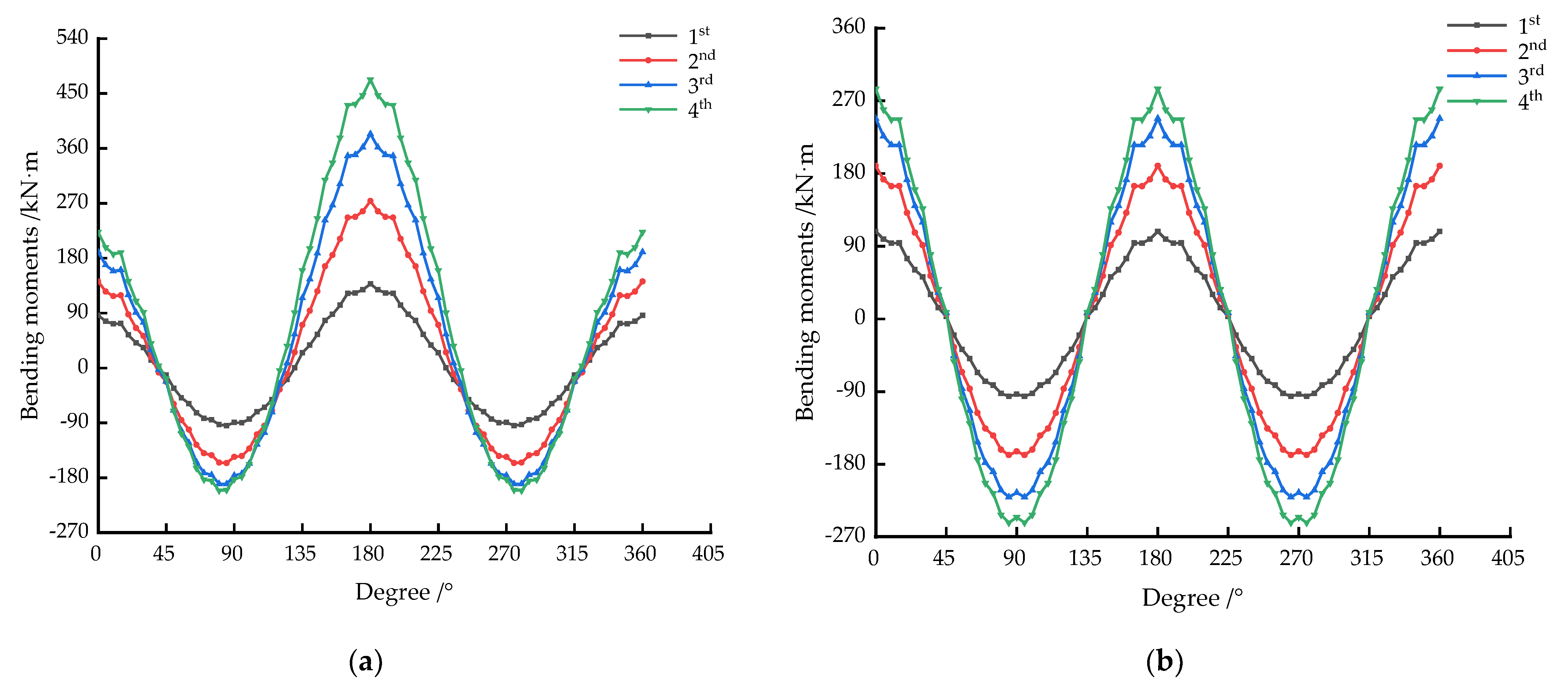
The analysis shows that the distribution modes for the bending rigidity for the two models, the beam-spring model and the modified uniform rigidity ring model, are different, which leads to a significant difference in the distribution of bending moments. Therefore, the modified uniform rigidity ring model is not applicable for the bending moment design of a tunnel structure.
(4)
Under the same loading condition, the axial forces, horizontal convergence deformations, and vertical convergence deformations for both models (the beam-spring model and the modified uniform rigidity ring model) are similar. Thus, the modified uniform rigidity ring model is applicable for the analysis of the structure convergence deformation and the interaction between the tunnel structure and the ground during operation.

Author Contributions

Investigation, D.H. and W.L.; methodology, D.H. and H.J.; theoretical analysis, D.H. and J.X.; numerical simulation, H.X. and J.X.; data analysis, H.J. and B.T. All authors have read and agreed to the published version of the manuscript.

Funding

This study was supported by the National Natural Science Foundation of China, grant number 52078213 and U1934208, the Natural Science Foundation of Jiangxi Province, grant number 20192ACBL21003.

Institutional Review Board Statement

Not applicable.

Informed Consent Statement

Not applicable.

Data Availability Statement

All data are available from the author.

Acknowledgments

The authors thank all reviewers for their great help in this article.

Conflicts of Interest

The authors declare no conflict of interest.

References

  1. Ai, Q.; Yuan, Y.; Mahadevan, S.; Jiang, X.M. Probabilistic degradation modelling of circular tunnels assembled from segmental linings. Struct. Concrete 2016, 17, 257–273. [Google Scholar] [CrossRef]
  2. Wang, F.; Shi, J.K.; Huang, H.W.; Zhang, D.M. Modified analytical solution of shield tunnel lining considering nonlinear bending stiffness of longitudinal joint. Tunn. Undergr. Space Technol. 2020, 106, 103625. [Google Scholar] [CrossRef]
  3. Lee, K.M.; Hou, X.Y.; Ge, X.W.; Tang, Y. An analytical solution for a jointed shield-driven tunnel lining. Int. J. Numer. Anal. Methods Geomech. 2001, 25, 365–390. [Google Scholar] [CrossRef]
  4. Lee, K.M.; Ge, X.W. The equivalence of a jointed shield-driven tunnel lining to a continuous ring structure. J. Can. Geotech. Eng. 2001, 38, 461–483. [Google Scholar] [CrossRef]
  5. Takamatsu, N.; Yoshida, K.; Koizumi, A. In-situ tests and consideration on shield tunnel in the longitudinal direction. J. Geotech. Eng. 1986, 1986, 131–140. [Google Scholar] [CrossRef] [Green Version]
  6. Koizumi, A.; Murakami, H.; Nishino, K. Study on the analytical model of shield tunnel in longitudinal direction. J. Geotech. Eng. 1988, 1988, 79–88. [Google Scholar] [CrossRef] [Green Version]
  7. Koizumi, A.; Murakami, H.; Takamatsu, N. Design method of segments at sharply curved section. J. Geotech. Eng. 1992, 1992, 111–120. [Google Scholar] [CrossRef] [Green Version]
  8. Zhu, H.H.; Cui, M.Y.; Yang, J.S. Design model for shield lining segments and distribution of load. Chin. J. Geotech. Eng. 2000, 22, 190–194. (In Chinese) [Google Scholar] [CrossRef]
  9. Huang, Z.R. Study on the Mechanics Character of Shield Tunnel Segment with Shell-Spring Model. Ph.D. Thesis, Hohai University, Nanjing, China, 2007. [Google Scholar]
  10. Gong, C.J.; Ding, W.Q.; Mosalam, K.M.; Selim, G.; Soga, K. Comparison of the structural behavior of reinforced concrete and steel fiber reinforced concrete tunnel segmental joints. Tunn. Undergr. Space Technol. 2017, 68, 38–57. [Google Scholar] [CrossRef]
  11. Liu, X.; Fang, Q.; Zhang, D.L. Mechanical responses of existing tunnel due to new tunnelling below without clearance. Tunn. Undergr. Space Technol. 2018, 80, 44–52. [Google Scholar] [CrossRef]
  12. He, H.; Zhou, S.H.; Guo, P.J.; Di, H.G.; Zhang, X.H. A theoretical model on the influence of ring joint stiffness on dynamic responses from underground tunnels. Constr. Build. Mater. 2019, 223, 69–80. [Google Scholar] [CrossRef]
  13. Li, S.H.; Li, P.F.; Zhang, M.J. Analysis of additional stress for a curved shield tunnel. Tunn. Undergr. Space Technol. 2021, 107, 103675. [Google Scholar] [CrossRef]
  14. Koyoma, Y.; Nishimura, T. The design of lining segment of shield tunnel using a beam-spring model. Proc. Tunn. Eng. JSCE 1997, 7, 279–284. [Google Scholar] [CrossRef]
  15. Working Group No.2, International Tunnelling Association. Guidelines for the design of shield tunnel lining. Tunn. Undergr. Space Technol. 2000, 15, 303–331. [Google Scholar] [CrossRef]
  16. Zhong, X.C.; Zhu, W.; Huang, Z.R.; Han, Y.W. Effect of joint structure on joint bending stiffness for shield tunnel lining. Tunn. Undergr. Space Technol. 2006, 21, 406–407. [Google Scholar] [CrossRef]
  17. Song, K.I.; Cho, G.C.; Chang, S.B.; Lee, I.M. Beam–spring structural analysis for the design of a tunnel pre-reinforcement support system. Int. J. Rock Mech. Min. Sci. 2013, 59, 139–150. [Google Scholar] [CrossRef]
  18. Do, N.A.; Dias, D.; Oreste, P.; Djeran-Maigre, I. The behaviour of the segmental tunnel lining studied by the hyperstatic reaction method. Eur. J. Environ. Civ. Eng. 2014, 18, 489–510. [Google Scholar] [CrossRef]
  19. Pham, A.T.; Sugimoto, M. The Effects of Tangential Ground–Lining Interaction on Segmental Lining Behavior Using the Beam-Spring Model. Appl. Sci. 2020, 10, 1084. [Google Scholar] [CrossRef] [Green Version]
  20. Yukinori, K. Present status and technology of shield tunneling method in Japan. Tunn. Undergr. Space Technol. 2003, 18, 145–159. [Google Scholar] [CrossRef]
  21. Lei, M.F.; Lin, D.Y.; Shi, C.H.; Ma, J.J.; Yang, W.C. A Structural Calculation Model of Shield Tunnel Segment: Heterogeneous Equivalent Beam Model. Adv. Civ. Eng. 2018, 2018, 9637838. [Google Scholar] [CrossRef] [Green Version]
  22. Kashima, Y.; Kondo, N.; Inoue, M. Development and application of the DPLEX shield method: Results of experiments using shield and segment models and application of the method in tunnel construction. Tunn. Undergr. Space Technol. 1996, 11, 45–50. [Google Scholar] [CrossRef]
  23. Blom, C.B.M. Design Philosophy of Concrete Linings for Tunnels in Soft Soils. Ph.D. Thesis, Technische Universiteit Delft, Delft, The Netherlands, 2002. [Google Scholar]
  24. Ye, F.; Gou, C.F.; Sun, H.D.; Xia, Y.X.; Zhou, Z. Model test study on effective ratio of segment bending rigidity of shield tunnel. Tunn. Undergr. Space Technol. 2014, 41, 193–205. [Google Scholar] [CrossRef]
  25. Li, X.J.; Zhou, X.Z.; Hong, B.C.; Zhu, H.H. Experimental and analytical study on longitudinal bending behavior of shield tunnel subjected to longitudinal axial forces. Tunn. Undergr. Space Technol. 2019, 86, 128–137. [Google Scholar] [CrossRef]
  26. Geng, P.; Mei, S.Y.; Zhang, J.; Chen, P.L.; Zhang, Y.Y.; Yan, Q.X. Study on seismic performance of shield tunnels under combined effect of axial force and bending moment in the longitudinal direction. Tunn. Undergr. Space Technol. 2019, 91, 103004. [Google Scholar] [CrossRef]
  27. Teachavorasinskun, S.; Chub-Uppakarn, T. Influence of segmental joints on tunnel lining. Tunn. Undergr. Space Technol. 2010, 25, 490–494. [Google Scholar] [CrossRef]
  28. Gong, W.P.; Wang, L.; Juang, C.H.; Zhang, J.; Huang, H.W. Robust geotechnical design of shield-driven tunnels. Comput. Geotech. 2014, 56, 191–201. [Google Scholar] [CrossRef]
  29. Yu, H.T.; Cai, C.; Bobet, A.; Zhao, X.; Yuan, Y. Analytical solution for longitudinal bending stiffness of shield tunnels. Tunn. Undergr. Space Technol. 2019, 83, 27–34. [Google Scholar] [CrossRef]
  30. Lu, L.; Sun, Y.F.; Liu, X.; Wang, X.Z.; Wang, W.P. Full-ring experimental study on the ultimate bearing capacity for the lining structure of the metro shield tunnel. Struct. Eng. 2012, 28, 134–139. (In Chinese) [Google Scholar] [CrossRef]
  31. Fang, Q.; Wang, G.; Yu, F.C.; Du, J.M. Analytical algorithm for longitudinal deformation profile of a deep tunnel. J. Rock Mech. Geotech. Eng. 2021, 13, 845–854. [Google Scholar] [CrossRef]
  32. Zhong, X.C.; Zhang, J.R.; Qin, J.S.; Zhu, W. Simplified calculation model for longitudinal equivalent bending stiffness of shield tunnel and its influence factors’ analysis. Rock Soil Mech. 2011, 32, 132–136. (In Chinese) [Google Scholar] [CrossRef]
  33. Ding, W.Q.; Gong, C.J.; Mosalam, K.M.; Soga, K. Development and application of the integrated sealant test apparatus for sealing gaskets in tunnel segmental joints. Tunn. Undergr. Space Technol. 2017, 63, 54–68. [Google Scholar] [CrossRef]
  34. Do, N.A.; Dias, D.; Oreste, P.; Djeran-Maigre, I. 2D numerical investigation of segmental tunnel lining behavior. Tunn. Undergr. Space Technol. 2013, 37, 115–127. [Google Scholar] [CrossRef]
  35. Li, P.F.; Wei, Y.J.; Zhang, M.J.; Huang, Q.F.; Wang, F. Influence of non-associated flow rule on passive face instability for shallow shield tunnels. Tunn. Undergr. Space Technol. 2021, 119, 104202. [Google Scholar] [CrossRef]
Figure 1. Straight beams spread from the installed segment ring and the modified uniform rigidity ring: (a) Installed segment ring; (b) modified uniform rigidity ring; (c) straight beam spread from the installed segment ring; (d) straight beam spread from the modified uniform rigidity ring.
Applsci 12 01901 g001
Figure 2. Force distribution and segment ring division.
Applsci 12 01901 g002
Figure 3. Beam-spring model.
Applsci 12 01901 g003
Figure 4. Simulated deformations under different loading conditions (unit: mm): (a) Beam-spring model; (b) modified uniform rigidity ring model; (c) deformation’s comparison of the beam-spring model; (d) deformation’s comparison of the modified uniform rigidity ring model (in order to better reflect the deformation of (a,b), the different segment ring model’s deformation are amplified 15 times in (c,d)).
Applsci 12 01901 g004
Figure 5. Simulated bending moments under different loading conditions (unit: kN·m): (a) Beam-spring model; (b) modified uniform rigidity ring model.
Applsci 12 01901 g005
Figure 6. Simulated axial forces under different loading conditions (unit: kN): (a) Beam-spring model; (b) modified uniform rigidity ring model.
Applsci 12 01901 g006
Table 1. Deformations measured in the full-scale test.
Loading ConditionsActual Load P1/kNActual Load P2/kNActual Load P3/kNDeformation Results of Different Testing Point/mm
74°105°180°255°286°
1st95.3245.9871.49−6.446.453.93−2.482.034.78
2nd163.1576.83122.36−22.1821.5112.48−7.38.6618.54
3rd213.0299.97159.76−63.0955.6632.18−18.7928.7255.21
4th248.92119.24186.69−107.8994.3655.21−31.5448.0192.55
Table 2. Joints’ bending stiffness obtained through back analysis.
Loading Conditionsk1/106 N·m/radk2/106 N·m/radk3/106 N·m/rad
1st342850
2nd131021
3rd649
4th4.22.57
Table 3. Effective ratios of the transverse bending rigidity and thickness reduction coefficients under different loading conditions.
Loading Conditions L = L L > L
η α η α
1st0.41490.74590.42120.7496
2nd0.21190.59620.2170.6009
3rd0.10260.46820.10590.4731
4th0.07180.41560.07420.4203
Table 4. Convergence deformations for the uniform rigidity ring and installed segment ring under different loading conditions (unit: mm).
Loading ConditionsUniform Rigidity RingInstalled Segment Ring
Δ D h u Δ D v u Δ D h i Δ D v i
1st3.61−3.869.08−9.76
2nd6.34−6.7631.52−33.17
3rd8.31−8.8584.94−87.71
4th9.5−10.14139.18−143.01
Δ D v u is the vertical convergence deformation of the uniform rigidity ring, Δ D v i is the vertical convergence deformation of the installed segment ring.
Table 5. Effective ratios of the transverse bending rigidity calculated using different methods.
Loading Conditions η 1 = D 1 + Δ D h u D 1 + Δ D h i η 2 = Δ D h u Δ D h i
1st0.99910.3976
2nd0.9960.2013
3rd0.98780.0979
4th0.97950.0683
Table 6. Convergence deformations for the modified uniform rigidity rings with effective ratios of the transverse bending rigidity calculated using different methods (unit: mm).
Loading
Conditions
( D 1 + D 2 ) π ( D 1 + D 2 ) π + 2 E I i = 1 n 1 k i Δ D h u Δ D h i D 1 + Δ D h u D 1 + Δ D h i
HorizontalVerticalHorizontalVerticalHorizontalVertical
1st8.8−9.189.08−9.73.61−3.86
2nd30.44−31.3431.52−33.576.37−6.78
3rd82.6−84.4884.94−90.448.42−8.96
4th135.28−138.14139.18−148.59.7−10.35
Table 7. Simulated deformations under different loading conditions (unit: mm).
Loading ConditionsDeformations of Beam-Spring Model/mmDeformations of Modified
Uniform Rigidity Ring Model/mm
90°180°270°90°180°270°
1st−6.374.54−3.394.54−4.594.4−4.594.4
2nd−23.515.76−9.6715.76−15.6715.22−15.6715.22
3rd−65.1342.47−22.5842.47−42.2441.3−42.2441.3
4th−107.5769.59−35.4469.59−69.0767.64−69.0767.64
Table 8. Simulated bending moments under different loading conditions (unit: kN·m).
Loading ConditionsBending Moments of Beam-Spring Model/kN·mBending Moments of Modified
Uniform Rigidity Ring Model/kN·m
90°180°270°90°180°270°
1st86.3−89.4137.9−89.4108.3−93.2108.3−93.2
2nd141.9−145.7273.8−145.7189.4−164.1189.4−164.1
3rd190.2−176.2383.8−176.2248.1−215.1248.1−215.1
4th222.6−182.4472.8−182.4284.7−245.4284.7−245.4
Table 9. Simulated axial forces under different loading conditions (unit: kN).
Loading ConditionsAxial Forces of Beam-Spring Model/kNAxial Forces of Modified
Uniform Rigidity Ring Model/kN
90°180°270°90°180°270°
1st−227.4−287.4−209.8−287.4−218.6−287.3−218.6−287.3
2nd−392.3−490.5−347.2−490.5−369.8−490.3−369.8−490.3
3rd−515.1−640.2−448.9−640.2−482−639.9−482−639.9
4th−611.7−749.9−526.2−749.9−568.9−749.6−568.9−749.6
Publisher’s Note: MDPI stays neutral with regard to jurisdictional claims in published maps and institutional affiliations.

