Article

Design and Implementation of Synthetic Aperture Radar (SAR) Field-Programmable Gate Array (FPGA)-Based Processor

1
Faculty of Engineering & Technology, Multimedia University, Melaka 75450, Malaysia
2
iRadar Sdn. Bhd., Melaka 75450, Malaysia
*
Author to whom correspondence should be addressed.
Appl. Sci. 2022, 12(4), 1808; https://doi.org/10.3390/app12041808
Submission received: 8 January 2022 / Revised: 26 January 2022 / Accepted: 29 January 2022 / Published: 10 February 2022

Abstract

:

Featured Application

Real-Time Processor for Synthetic Aperture Radar.

Abstract

Synthetic aperture radar (SAR) is a unique imaging radar system that is capable of obtaining high-resolution images by using signal-processing techniques while operating in all weather and in the absence of a light source. The potential of SAR in a wide range of applications has led to new challenges in digital SAR processor design. On-board storage of SAR raw data is often not practical for real-time applications. The design of digital SAR processors is always restricted by the available space of the carrier system, data transfer rate, payload capacity and on-board power supplies. As reported in the literature, although customized hardware solutions could offer the desired performance, they are not feasible for low-volume production. This research aims to design and develop an efficient digital SAR processor by using field-programmable gate array (FPGA) with the consideration of hardware resources, processing speed and precision. In this paper, a hardware implementation of an FPGA-based SAR processor is presented. The implementation and architecture of the proposed SAR processor are highlighted in this paper. A MATLAB-based SAR processing range-Doppler algorithm (RDA) was developed as the benchmark for the development of an SAR processor. The target device, Altera Stratix IV GX FPGA EP4SGX230KF40C2, was selected for the design and implementation of an FPGA-based SAR processor. Comprehensive evaluations of the performance of the proposed SAR processor in terms of precision, timing performance and hardware resource utilizations are also presented. The proposed FPGA-based digital SAR processor achieves optimum performance in processing SAR signals for image formation. Evaluation shows that the designed SAR processor is capable of processing SAR images with ±1% difference error as compared to SAR images processed by MATLAB. The results also show a reduction in hardware usage via the implementation of an FPGA-based FFT/IFFT coprocessor. These promising results prove that the performance of the proposed processor is satisfactory and the achieved processing time, as well as the power consumption of the processor, outperformed existing implementations.

1. Introduction

Synthetic aperture radar (SAR) is a side-looking radar that achieves fine along-track resolution by taking advantage of radar motion to synthesize a large antenna aperture [1,2] and possesses many advantages compared with traditional optical imaging methods. In 1952 separate but similar concepts proposed by Goodyear and a team at the University of Illinois led to the early development of SAR [3]. The first SAR image was electrically processed and displayed on frequency analysers [4]. This system, as a proof of concept, was bulky for an airborne system. The next generation of processing was done optically [5], which dramatically enhanced the image quality down to 15-m resolution and reduced the equipment size enough to fit into the back of a van.
Interest in digital SAR processors began in the late 1970s. One of the earliest studies on data reduction using parallel processors was performed by Jet Propulsion Laboratory (JPL) in 1976 to produce SEASAT SAR imagery [6]. Another digital SAR processor was developed in 1978 by a company called MacDonald Dettwiler [7]. Although this processor was slower than its predecessors (it took hours to process a few seconds of data), it showed an improvement in image quality. Since then, digital systems have progressed in leaps and bounds. Advancements in processor technology promise not only faster but also more space- and energy-efficient digital processors.
Another early work on the implementation of hardware architecture of digital SAR processors was introduced by Prati and Rampa [8]. The authors proposed a multiprocessor single instruction multiple data (SIMD) architecture in order to meet the requirement of high computation throughput. The required processing parameters of the system is every 256 range lines of 2048 real samples must be processed in less than 3.2 s. In 1996, Meisl, Ito and Cumming designed a parallel SAR processor capable of processing high-resolution SAR data based on special-purpose digital-signal processors (DSP), general-purpose microprocessors and general-purpose DSP [9]. The authors showed that general-purpose-microprocessor-based SAR processors offer greater flexibility, keeping the development cost low. Meanwhile general-purpose DSP-based SAR processors offer the highest performance. However, the tradeoff is less flexibility, requiring more design work to be done.
In 2002, Zhu, Hong, Wang and Yuan introduced a DSP hardware implementation of an SAR raw data compressor [10]. The processor consists of two main modules, which are generic array logic (GAL) and in-system programmable large scale integrated circuit (ISPLSIC), in order to maintain system flexibility and ease of maintenance. The overall processor allows the main data to be processed in DSP. In 2004, a novel generation of compact airborne SAR on-board processor was introduced by Nolte, Simon-Klar, Langemeter, Kirscht and Pirsch [11]. The processor uses a wavenumber domain algorithm to further reduce the output data rate in the SAR raw data processing cycle. The SAR processor is a system on chip (SoC) that maps and integrates the entire SAR processing chain into a single semiconductor chip. In recent years, commercial off-the-shelf (COTS) components have gained popularity in SAR applications. Wang and Ali demonstrated the use of a low-power multicore digital signal processor for the application of SAR [12]. However, the demanded parallelism processing of the SAR data can be achieved via multicore DSP instead of single-chip.
Since SAR is a remote sensor used for global coverage and monitoring, it generates a large amount of SAR raw data via the receiver. For instance, ERS-1 SAR, launched by the European Space Agency (ESA) in 1991, generated few hundred MBs of SAR raw data for a duration of 10 s. The generation of two-dimensional images from SAR raw data by using SAR signal-processing techniques is a highly computationally intensive task. It demands heavy computational power and large memory for operations. Therefore, using a general computer is not an optimized implementation, as the required processing power cannot be achieved by a sequentially working single-processor system. With the development of wideband technology signal- and information-processing technology, radar coverage, detection accuracy and resolution have been greatly improved in SAR imaging technology. Meanwhile, for the application of radar detection and remote sensing with high resolution and wide swath, the amount of data has been greatly increased. Therefore, the radar is required to have low latency and real-time processing capability under the constraints of size, weight and power consumption [13]. Exploitation of parallelisation by splitting the algorithm into independent and isolated data blocks in order to achieve parallel processing is an essential implementation.
Therefore, improvement of the hardware implementation of SAR processors is needed due to inflexibility of customised hardware solutions, as well as stringent space and power requirements in the SAR platform. An FPGA-based system is one of the best choices for hardware implementation of an efficient digital SAR processor due to its flexibility, reconfigurability and exploit pipelining [14]. An FPGA-based system is able to fulfil the demands of massively parallel processing, lower power consumption and smaller form factor. Bases on all of the mentioned advantages of an FPGA-based system, it is beneficial to select an FPGA-based system for the implementation of SAR processors in this research work. This research was developed based on an unmanned arial vehicle (UAV) SAR operating in monostatic configuration with the transmitting antenna and receiving antenna collocated. Therefore, RDA is the most suitable algorithm [15]. The major contribution of this research work is the development and establishment of an efficient airborne digital SAR signal processor using FPGA. The proposed FPGA-based digital SAR processor achieves optimum performance in processing SAR signals for image formation. A customised, generic, reconfigurable fast Fourier transform and its inverse coprocessors in FPGA were also designed and developed for the hardware implementation of the SAR processing algorithm. The results show a reduction in hardware usage via the implementation of an FPGA-based FFT/IFFT coprocessor. The achieved processing time and power consumption also outperformed the existing implementations.

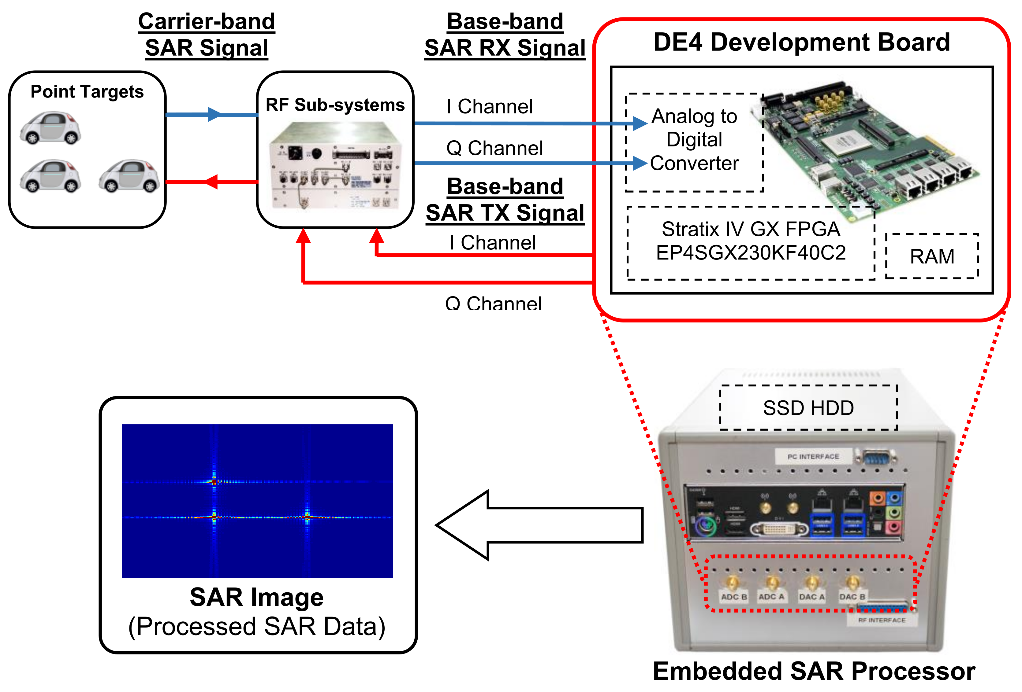
2. Implementation of FPGA-Based On-Board SAR Processor

FPGA has unique characteristics of reconfigurability, application power efficiency and high throughput rate. This allows users to perform various direct-control operations for the implementation of a digital system, including the digital SAR processor. NASA and USAF identified that on-board processing is an indispensable technology that requires improvement of the performance of SAR systems [16]. In 2007, Kuon and Rose showed that the main advantage of FPGA is its reprogrammability, which makes it the best matched candidate for the implementation of real-time processing systems. In particular, researchers from JPL proposed an on-board FPGA-based SAR processing system to be implemented for the application of SAR [16]. The proposed architecture consists of the major objectives and several challenges for an FPGA-based SAR processor. This proposal shows that the implementation of an FPGA-based on-board processor in SAR mission is feasible. Lesnik et al. from the Military University of Technology, Poland designed and implemented a real-time SAR image processor with commercial off-the-shelf (COTS) hardware, i.e., the Xilinx FPGA Virtex-5 SX95T and Texas Instruments C6455 DSP in 2012 [17]. In 2016, NASA has developed an airborne SAR testbed called UAVSAR. In this project, the UAVSAR on-board processor (OBP) design was derived from a JPL-developed ground-based software processor, which comprised a commercial μP board, a custom FPGA processing board and a custom interface board. This was a hybrid architecture, where computations were divided between FPGAs, which are better suited to rapid, repetitious computations, and a μP with a floating-point coprocessor, which is better suited to less frequent and irregular computations [18]. The Beijing Institute of Technology developed an onboard real-time SAR processor using a field-programmable gate array—application-specific integrated circuit (FPGA-ASIC) hybrid, heterogeneous, parallel accelerating architecture in 2017 [19]. In 2019, Nanjing University of Aeronautics and Astronautics, China successfully implemented a miniaturized synthetic aperture radar (MiniSAR) signal-processing system via a Virtex7-XC7VX690T evaluation board [20]. The main advantages of FPGA are its reprogrammability, which makes it the best matched candidate for the implementation of real-time processing systems [21].
By implementing an FPGA-based SAR on-board processor, it can be adapted to different SAR systems with different specifications, as the processor is scalable and reconfigurable according to user requirements. As long as the hardware resources are sufficient, the processor can be reconfigured at any time in order to match the desired requirement. Scalable is defined as the ability of processing power and architecture of the processor to be easily reconfigured within a single hardware platform and without any physical hardware modifications. Besides, an FPGA-based SAR processor has the ability to make trade-offs between hardware and software in order to maximise the efficiency and performance of the processor. For instance, if a bottleneck is identified to be caused by the SAR software algorithm, a customised FPGA-based coprocessor can be designed for the specific algorithm. The coprocessor is attached to the main processor through low-latency channels for real-time on-board processing due to high throughput rate.

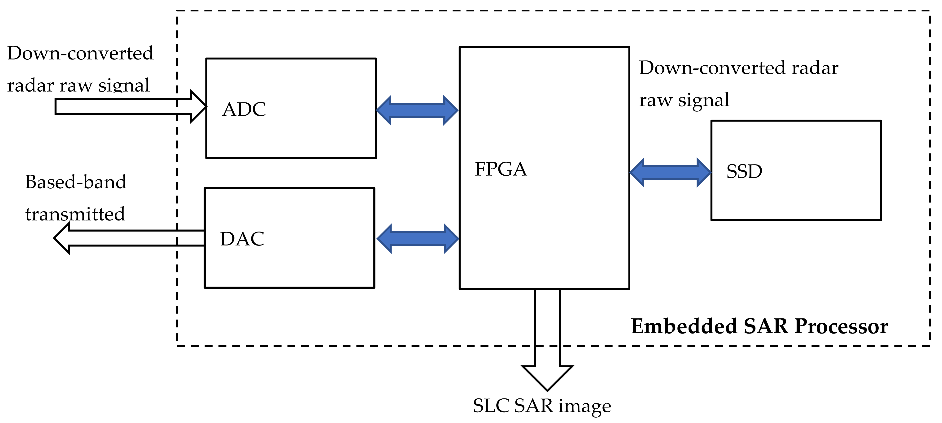
2.1. SAR Processor Architecture

The major submodules of the SAR processor system are listed and detailed as below:
(i)
Analogue-to-Digital Converter (ADC) and Digital-to-Analogue Converter (DAC)
This module acts as the analogue interface of the system. The ADC digitizes the incoming analogue signal (radar return echo), and the DAC produces the baseband analogue radar signal, with the frequency typically modulated by a continuous wave pulse signal.
(ii)
FPGA-based Embedded SAR Processor
Acts as ADC and DAC control and data buffer. This portion of the system interfaces and controls data flow with the DAC and ADC chips. All signalling, including operating modes, are controlled by this block.
The main task of the FPGA module is to execute the SAR image-formation algorithm process and output the SAR images. In this module, FFT/IFFT, complex multiplication and other operations are performed on the raw data and produce the correct SAR images.
(iii)
Data Storage
The solid-state device (SSD), which it is made of non-volatile memory chips, is used as data storage. The SSD is used to store the received SAR raw data, as well as the processed SAR images.
A detailed functional block diagram of the embedded SAR processor is illustrated in Figure 1. The output of the SAR processor is the level 1 single-look complex (SLC) SAR image. The generated SAR image can be further processed to level 2 by performing advanced SAR processing, such as interferometry or polarimetric SAR processing.

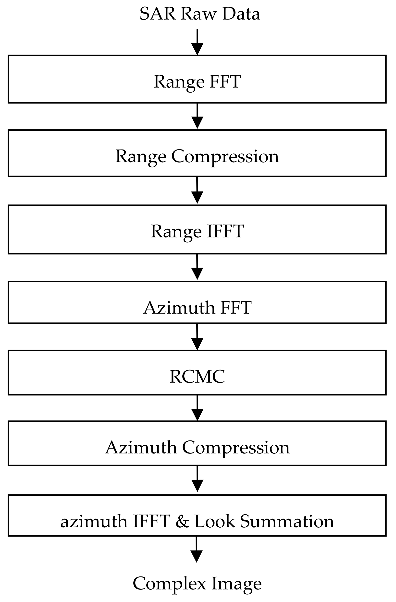
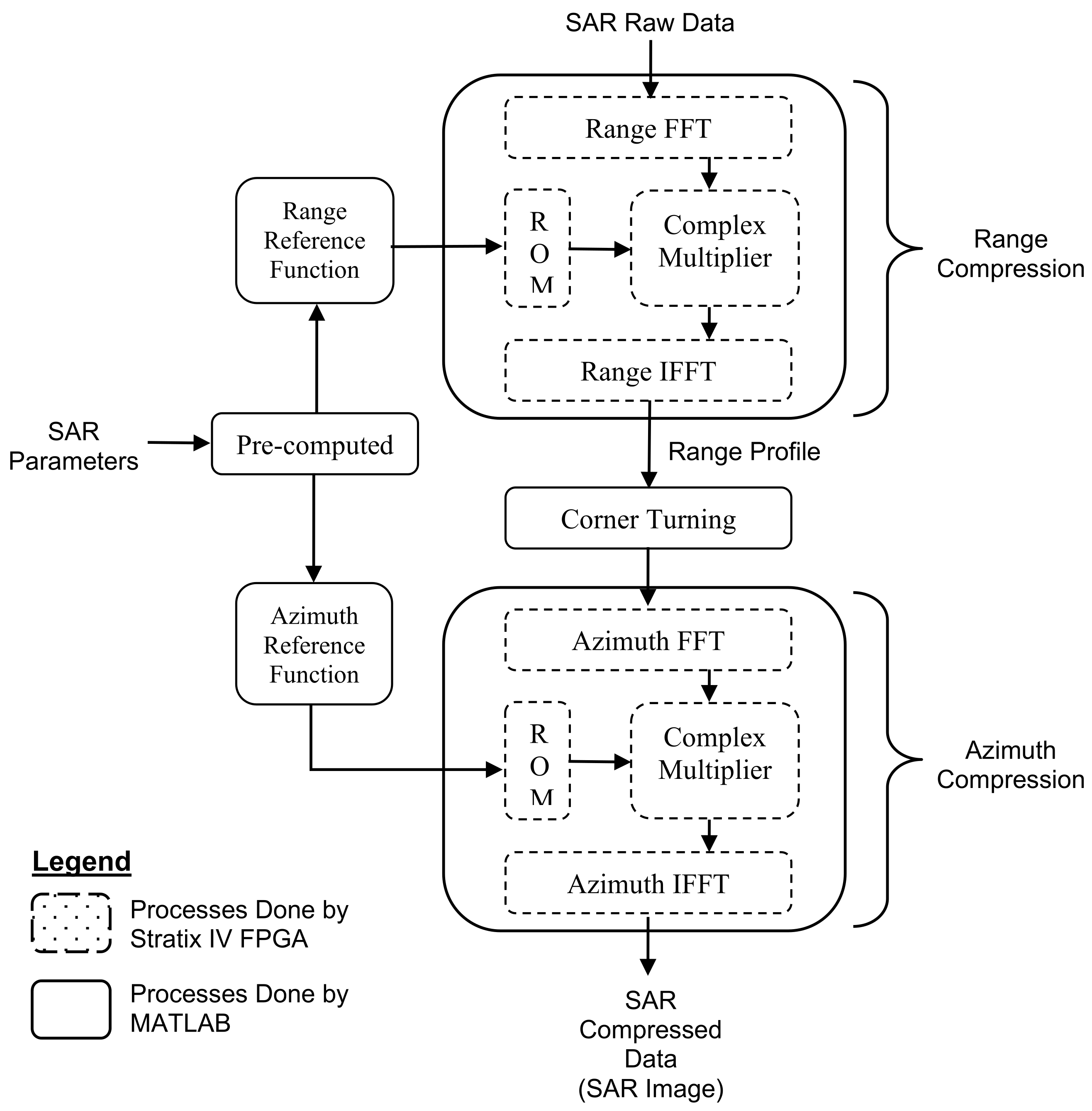
2.2. SAR Image-Formation Algorithm

In the application of digital SAR processing, signal processing poses a significant challenge because of its stringent computation-power and data-storage requirements. A high-resolution SAR system captures return echoes and yields huge amounts of raw data. The size of these data is dependent on several parameters, such as dynamic range, spatial resolution and sampling frequency of the SAR system. In the software layer of the digital SAR processor, the most commonly used SAR processing techniques and algorithms are the range-Doppler algorithm (RDA), chirp scaling algorithm (CSA) and the Omega-K algorithm (ωKA) [22,23,24,25,26,27,28,29,30,31,32,33,34].
RDA is a simple and mature SAR image-processing algorithm with a relatively small computation load. It is suitable for real-time processing. Basically, it divides the SAR echo-signal-processing into two one-dimensional processes in cascade, i.e., range compression followed by azimuth compression. If the size of the range migration is not more than one range resolution cell, i.e., the target impulse response is within the range resolution in a cell, it can be considered as a straight line. Thus, compensation for range-cell migration is not required. In summary, real-time signal-processing algo-rithms for airborne SAR can be implemented by RDA. An RDA block diagram is shown in the Figure 2.

2.3. SAR Processor Implementation

As described in Section 2.2, an SAR image-formation algorithm is a computationally intensive task that involves several complex operations and algorithms. FFT and IFFT play an important role in SAR processing, which motivates extensive study of FFT/IFFT algorithms for hardware implementation. FFT and IFFT coprocessors have been successfully developed and will be deployed in the implementation and integration of FPGA-based SAR processors [33]. The overall development of the SAR processor was based on hardware blocks described in Section 2.1. The submodules of the FFT coprocessor, IFFT coprocessor, complex multiplier and ROMs were integrated and used to implement the RDA into the Altera Stratix IV GX FPGA EP4SGX230KF40C2 device, which is located on the Altera DE4 development board. The overall block diagram for the hardware implementation of the FPGA-based SAR processor is illustrated in Figure 3.
Implementation and evaluation were carried out by a full setup for the SAR processor. The baseband transmit chirp IQ signals (Channel A & B) were generated internally by the embedded SAR processor. They were converted into analog form by DAC and fed into the TX port of the RF module for transmission. The RF module mixes the IQ signals and up-converts them to the carrier band. After mixing, the signal is transmitted to the delay line, which simulates the existence of point targets, as it delays the transmitting signal. The delayed signal is returned to the RX port of the RF module and down-converted into an IQ baseband signal. The baseband-received signals are captured and digitised by the dual-channels analogue-to-digital-converter. This captured signal is the SAR raw data and is loaded into the proposed FPGA-based SAR processor for processing operations in order to form the SAR image.
The captured SAR raw data with point targets is fed into the SAR processor in order to process and form an SAR image through the processing operations. Figure 4 portrays the block-diagram partitioning of the embedded FPGA-based SAR processor architecture that is implemented by instantiating the proposed FFT, IFFT, complex multiplier and ROM. Based on the specific SAR parameters, the range-reference function and the azimuth reference function are precomputed in MATLAB, and these precomputed functions are stored in the ROM of FPGA so that the matched filtering operation can be performed later.
In Figure 4, dotted labelling represents the sections implemented in FPGA. The complex multiplier, as designed by Lee, is used in the implementation of the matched-filtering operation in the range of compression, as well as complex multiplication in the azimuth compression [34]. Range and azimuth compressions share a similar architecture, except for the data stored in the ROMs and the transform length for FFT and IFFT. For range compression, the FFT and IFFT transform lengths are 1024 points, as every range bin consist of 1024 samples, while for azimuth compression, the FFT and IFFT transform lengths are 2048 points, as there are a total of 2048 azimuth bins.

3. Performance Evaluation of the Proposed SAR Processor

Performance evaluation of this proposed SAR processor was conducted by evaluating the precision comparison of the processed SAR image using both MATLAB and the proposed SAR processor. Total hardware resources utilised and total time taken in order to form a SAR image were evaluated in the same manner. The evaluation and simulations are based on the parameters listed in Table 1.

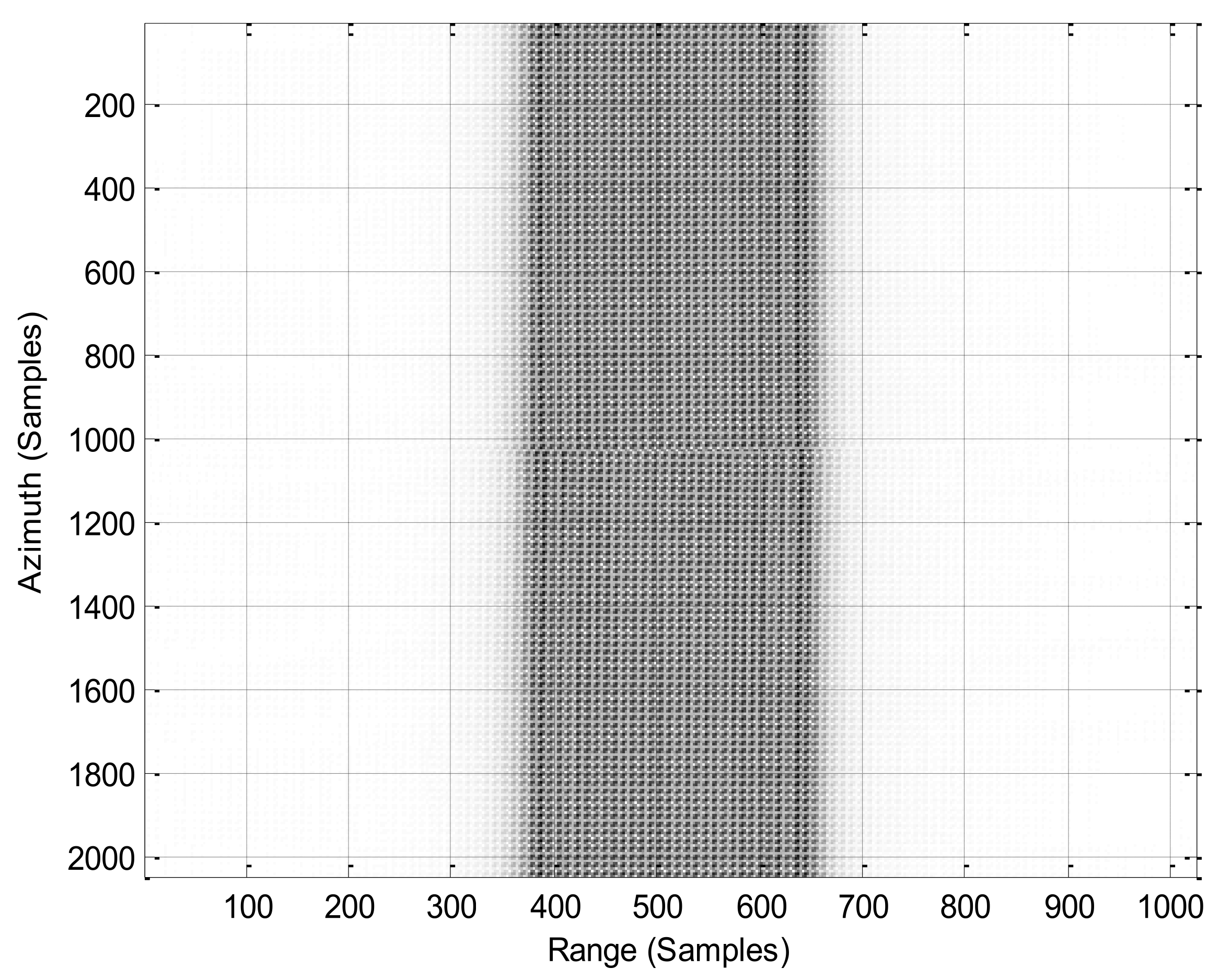
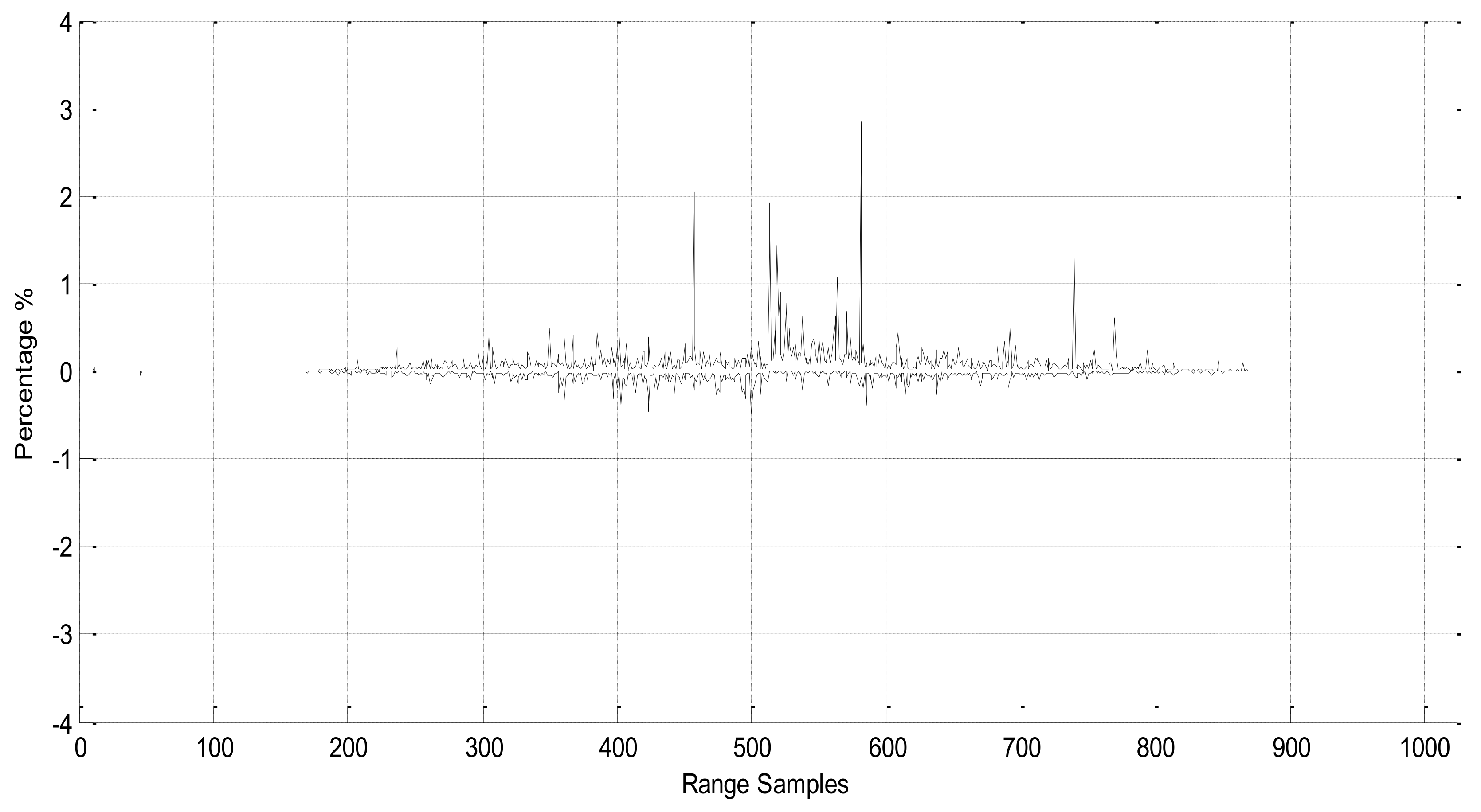
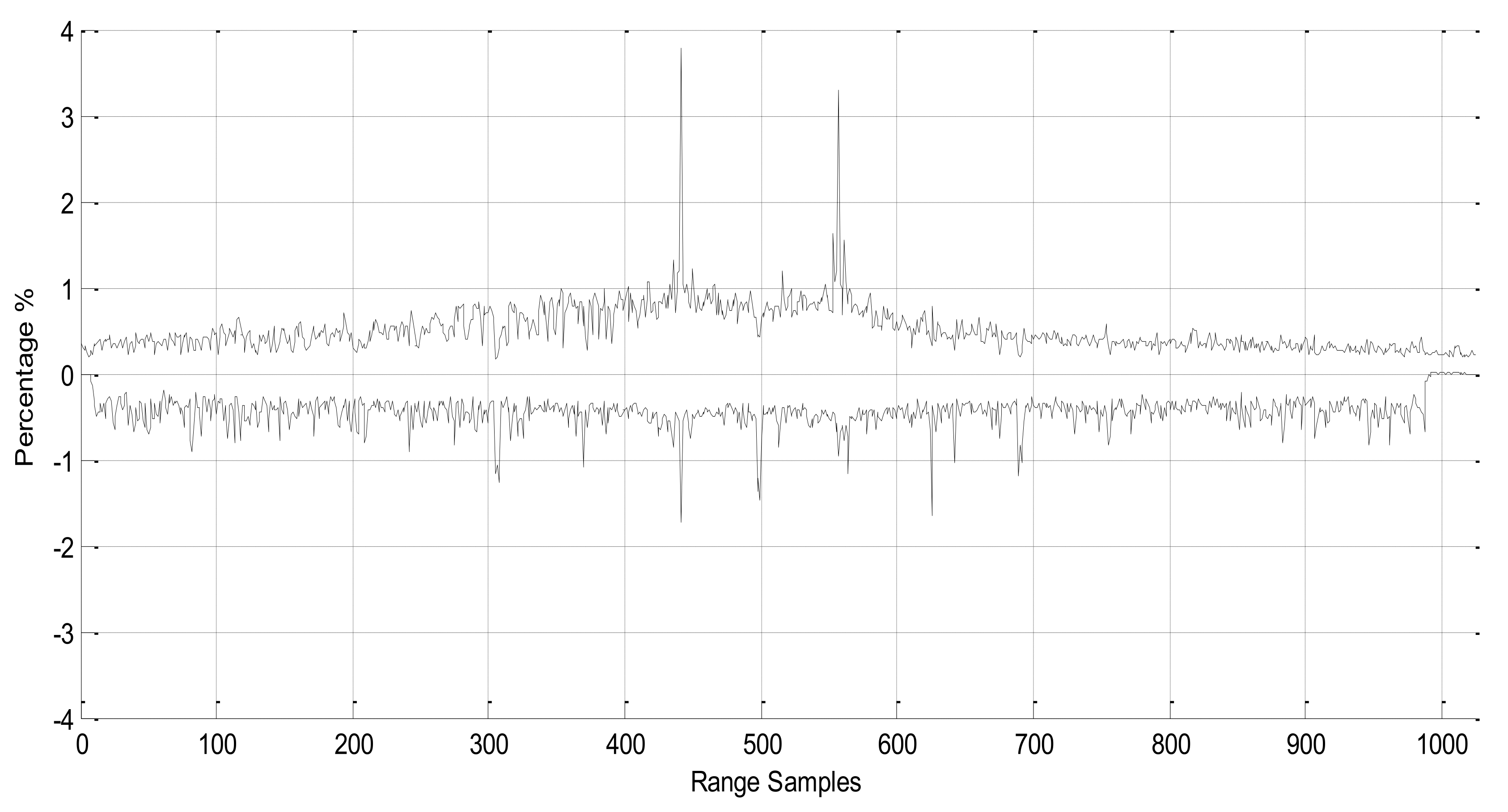
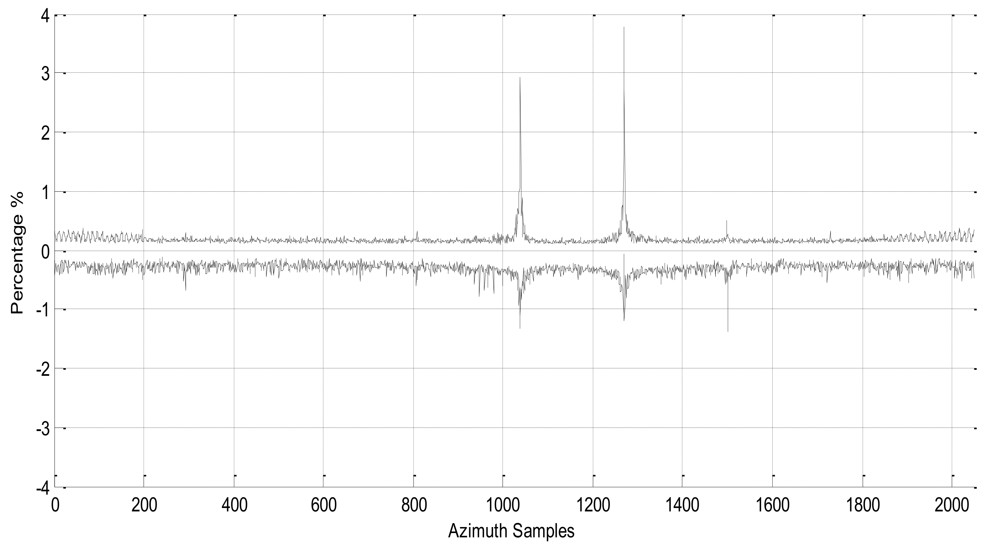
3.1. Precision Comparison of the Proposed SAR Processor and MATLAB-Based SAR Processor

The proposed SAR processor, as in Figure 4, was synthesised and implemented into the FPGA device, Altera Stratix IV GX series EP4SGX230KF40C2, located within the embedded SAR processor, a DE4 development board. Captured raw SAR data is loaded into the proposed SAR processor for the RDA processing operations. The intermediate results of the SAR processor were observed and compared with the results of RDA in MATLAB in terms of precision and accuracy. The evaluation was conducted starting from the range compression by comparing the SAR raw data that transformed into the frequency domain by MATLAB and that of the proposed SAR processor. In the SAR image, brighter colours represent lower reflection from the targets, and darker colour indicates stronger reflection from the targets. Figure 5 shows the magnitude plot of the SAR raw data that is transformed into the frequency domain by using the built-in FFT function in MATLAB, while Figure 6 shows the magnitude plot of the SAR raw data that is transformed into the frequency domain by the proposed SAR processor. It can be observed that there are very significant similarities in the patterns of the two images.
In order to clearly evaluate the differences between the two images, the range-profile differences between the two results were computed, and the MATLAB result was treated as reference for the calculation of the differences. MATLAB was used as the reference of comparison, as the range-profile generation. SAR image formation via MATLAB is already well established, and its built-in functions, such as FFT and IFFT, have proven to be correctly implemented. For quantitative comparison, the differences between the results of FPGA and MATLAB were calculated based on the equation below.
Δ   ( % ) = Range   Profile   of   FPGA Rang   Profile   of   MATLAB Range   Profile   of   MATLAB × 100 %
Since SAR image is formed by multiple range lines, the most positive and the most negative differences throughout all the range lines were calculated. Figure 7 illustrates these differences in the SAR raw data range profile in the frequency domain. The figure shows that the majority of differences in the results are in the range of ±0.5%, with a maximum error of no more than 3%. This error is mainly due to the quantisation error from the ADC. From the difference error, it can be concluded that the range profile is around 1% of the quantisation noise floor. This noise floor exists in the raw data even when there is no point target.
After the data were transformed into the frequency domain by FFT, they were then passed through the matched-filtering process by multiplying the data with the precomputed range reference function using the designed complex multiplier. The output of the matched filter is transformed into time domain, and the data appear as range-compressed data. Figure 8 shows the range-compressed data processed by MATLAB based SAR processing software, while Figure 9 shows the range-compressed data processed by the proposed SAR processor. In the figures, the similarities between the range-compressed data are visually identical. Hence, the differences between these two sets of range-compressed data are computed in the same manner in order to obtain a quantitative comparison. Figure 10 shows the difference in SAR range-compressed data in the range profile. The majority differences of the results are acceptable, and they are in the range of ±0.5%, as indicated in the figure. Only a few samples had spikes of +2% to +3% of errors that can be neglected. In Figure 10, it can be noticed that the overall similarities between these two compressed data are considered reasonably high, as the expected patterns are recognisable.
After evaluating the intermediate results for range compression, evaluation was carried out by observing the intermediate results for azimuth compression. The evaluation was conducted in the same manner as for range compression. The range-compressed data are transformed into the range-Doppler domain by MATLAB and the proposed SAR processor. Figure 11 shows the magnitude plot of the range-compressed data that are transformed into the range-Doppler domain by using MATLAB. Figure 12 shows the range-compressed data being transformed into the same domain by the proposed SAR processor. From both figures, recognisable patterns with high similarities can be observed in between both results. In order to obtain a quantitative comparison, the differences between the results were computed in the same manner. The range-profile difference error is illustrated in Figure 13. Figure 13 shows that the differences are in the acceptable tolerance, as there are only a few portions of range samples with an error in the range of ±1.5%.
After the data were transformed into the range-Doppler domain, they were then passed through the azimuth compression, which consist of the azimuth-matched filtering process. The data were multiplied with the precomputed azimuth reference function using the designed complex multiplier. The output of the matched filter is transformed into time domain and the data appear as azimuth-compressed data. The final output of the SAR processor is the azimuth compressed data, which is the single-look complex SAR image. Figure 14 shows the azimuth-compressed data processed by MATLAB, while Figure 15 shows the azimuth-compressed data processed by the proposed SAR processor.
From the figures, the similarities between the azimuth-compressed data are visually identical. Thus, in order to obtain a quantitative comparison, the differences between these two azimuth-compressed data were computed and portrayed as Figure 16 for the range profile and Figure 17 for the azimuth profile, respectively.
Figure 16 and Figure 17 show that the majority of differences are in the range of ±1%. This error is mainly due to the quantisation error from the system. It can also be concluded that both profiles consist of a quantisation noise floor around ±0.5%, even when there is no point target in the data. Another observation from the difference is that when there is a point target in the image for a particular range and azimuth samples, the difference error also increases. The sample points with the reflected point targets have a slightly higher difference error of about 3.5% as compared to the background. This is mainly due to the low dynamic range of the fixed-point data formatting used in the proposed processor.
Overall, the processed SAR image is satisfactory, as the proposed SAR processor is capable of processing the SAR raw data and forming the SAR image with an acceptable low margin of difference error. Based on the compressed SAR image, the results are regarded as satisfactory because the overall similarities between the two SAR images are considered identical, as the expected patterns are recognisable.

3.2. Timing Performance Analysis

After evaluating the performance of the proposed SAR processor in term of precision, the processor was evaluated in terms of timing performance. In the SAR raw data, every single range consisted of 4096 samples, and the SAR sensor moved along the flight path to capture 2048 azimuth lines, meaning the produced SAR image has dimensions of 4096 × 2048. Therefore, in the range compression, a 4096-FFT coprocessor was used in order to transform one line of range into the frequency domain and perform the matched filtering, followed by 4096 IFFT.
The time taken for a single 4096 FFT/IFFT was 168.59 μs. The time taken for complex multiplication in matched filtering for one range line of 4096 samples is 12.04 μs (one clock cycle, 2.94 ns × 4096 samples). The whole operation was repeated 2048 times in order to complete the range compression of the SAR raw data. Thus, the time taken to complete 4096 points FFT and IFFT for 2048 azimuth samples was 345.27 ms for each operation, while the complex multiplication took 24.66 ms. The processing time spent for such SAR raw data samples sizes are tabulated under the range-compression column in Table 2. Meanwhile, the azimuth compression was repeated in the same manner, except a 2048-FFT coprocessor was used, as there was a total of 2048 azimuth lines. The time taken for a single 2048 FFT/IFFT was 78.27 μs. Hence, the time taken to complete 2048-point FFT and IFFT for 4096 range samples was 320.6 ms for each operation, while the complex multiplication was the same, at 24.66 ms. The processing time spent for the azimuth compression is tabulated under the azimuth column of Table 2. The total summation of the time is 474.31 ms, which represents the total time required by the proposed SAR processor in order to process an SAR image.

3.3. Hardware Resource Utilisation

In term of hardware resource utilisations, the proposed SAR processor was evaluated by synthesis and implemented into the FPGA device, Altera Stratix IV GX series EP4SGX230KF40C2 is, which is located inside the embedded SAR processor, an DE4 development board. There are six metrics to be considered in the area of hardware resource utilisations, i.e., the combinational adaptive look-up table (ALUT), total dedicated logic registers, total pins, total block-memory bits, M9K block memory and DSP block 18-bit elements [14]. Performance evaluations were conducted by comparing the hardware resource utilisations in six metrics for both the Altera IP FFT/IFFT coprocessor and the proposed FFT/IFFT coprocessor with a transform length of 2048 points and 4096 points. The evaluations are tabulated in Table 3. From Table 3, it is noticeable that for all transform lengths of the FFT/IFFT coprocessors, the proposed FFT/IFFT coprocessors used less hardware resources in all six metrics as compared to the Altera IP FFT/IFFT coprocessor. The reduction in hardware usage significantly helps in the development of the integrated SAR processor, as more hardware resources quota can be allocated to other submodule designs in the SAR processor.
Total hardware resource utilisation for the proposed SAR processor is summarised and tabulated in Table 4. The hardware utilisations are partitioned into two main sections, which are the range-compression module and the azimuth-compression module. The range-compression module comprises a 4096-FFT coprocessor, a complex multiplier, a ROM precomputed for the range-reference function and, lastly, a 4096-IFFT coprocessor. As for the azimuth-compression module, it consists of a 2048-FFT coprocessor, a complex multiplier, a ROM precomputed for the azimuth reference function and, lastly, a 2048-IFFT coprocessor. Overall, the range-compression module utilises more hardware resources as compared to the azimuth-compression module. This is mainly due to the 2048-point FFT/IFFT modules used in the azimuth compression, while the range-compression module consist of 4096 points FFT/IFFT.
The comparison of the performance between the proposed system and the previous SAR onboard processor is summarised in Table 5. The proposed system is to be used for low-altitude UAV-based SAR, with an image size of 4096 × 2048 tested in this project. The proposed system is suitable as a near-real-time implemetation due to the total procesing time of 1.38 s. It also achieved a shorter processing time compared to the previously developed system. The power consumption is also relatively lower compared to that of other implementations.

4. Conclusions

This research aimed to design and develop an efficient digital FPGA-based SAR processor with consideration of hardware resources, processing speed and several optimization schemes. In-depth exploration and discussion of the architectures of the proposed FPGA-based SAR processor was carried out. A MATLAB-based SAR processing algorithm RDA was developed as the benchmark for the development of the SAR processor. The Altera Stratix IV GX FPGA EP4SGX230KF40C2 was used for the design and implementation of an FPGA-based SAR processor. Comprehensive evaluations and analyses were conducted to evaluate all the submodules of the FPGA-based SAR processor. The evaluation shows that overall, the SAR processor is capable of processing SAR images with a ±1% difference error as compared to SAR images processed by MATLAB. The investigations also show a reduction in hardware usage via the implementation of an FPGA based FFT/IFFT coprocessor. These promising results have proven that the performance of the proposed processor is satisfactory and the achieved processing time, as well as the power consumption of the processor, outperformed existing implementations. Recommendations for future work include extending the development of FFT/IFFT coprocessors using other FFT algorithms, such as Radix-2 constant-geometry structure, Radix-22 single-path delay feedback and mixed Radix FFT in order to reduce the processing time in the RDA. In this work, a proposed FPGA-based SAR processor was developed based exclusively on RDA. Nevertheless, it can be further extended to other SAR algorithms, such as chirp scaling (CSA), ωKA and spectral analysis (SPECAN) algorithms.

Author Contributions

Conceptualization, Y.K.C. and V.C.K.; methodology, Y.C.L.; software, Y.C.L.; validation, Y.K.C. and V.C.K.; formal analysis, Y.C.L.; investigation, Y.C.L.; resources, Y.K.C. and V.C.K.; data curation, Y.C.L.; writing—original draft preparation, Y.C.L.; writing—review and editing, Y.K.C.; supervision, V.C.K.; project administration, Y.K.C.; funding acquisition, Y.K.C. All authors have read and agreed to the published version of the manuscript.

Funding

This research was supported by MOSTI E-Science Fund, 04-02-01-SF0200.

Institutional Review Board Statement

Not applicable.

Informed Consent Statement

Not applicable.

Conflicts of Interest

The authors declare no conflict of interest.

References

  1. Stimson, G.W. Introduction to Airborne Radar; SciTech Pub: Tamil Nadu, India, 1998. [Google Scholar]
  2. Chan, Y.K.; Koo, V.C. An introduction to synthetic aperture radar (SAR). Prog. Electromagn. Res. B 2008, 2, 27–60. [Google Scholar] [CrossRef] [Green Version]
  3. Wiley, C.A. Synthetic Aperture Radars. IEEE Trans. Aerosp. Electron. Syst. 1984, 21, 440–443. [Google Scholar] [CrossRef]
  4. Gart, J.H. Electronics and Aerospace Industry in Cold War Arizona, 1945–1968: Motorola, Hughes Aircraft, Goodyear Aircraft; Arizona State University: Tempe, AZ, USA, 2006. [Google Scholar]
  5. Cutrona, L.; Leith, E.; Palermo, C.; Porcello, L. Optical data processing and filtering systems. IRE Trans. Inf. Theory 1960, 6, 386–400. [Google Scholar] [CrossRef]
  6. Wu, C. A Digital System to Produce Imagery from SAR Data. In Proceedings of the AIAA Conference: System Design Driven by Sensors, Pasadena, CA, USA, 18–20 October 1976. [Google Scholar]
  7. Kramer, H.J. Observation of the Earth and its Environment: Survey of Missions and Sensors; Springer Science & Business Media: Berlin/Heidelberg, Germany, 1992. [Google Scholar]
  8. Prati, C.; Rampa, V. Real-time Parallel Processor for On-board Airborne Synthetic Aperture Radar (SAR). IEEE Int. Symp. Circuits Syst. 1990, 4, 2905–2908. [Google Scholar]
  9. Meisl, P.G.; Ito, M.R.; Cumming, I.G. Parallel Processors for Synthetic Aperture Radar Imaging. In Proceedings of the IEEE Proceedings of International Conference on Parallel Processing, Ithaca, NY, USA, 12–16 August 1996; Volume 2, pp. 124–131.
  10. Zhu, L.; Hong, W.; Wang, J.; Yuan, Y. DSP hardware implementation of BAVQ encoding for SAR raw data. In Proceedings of the IEEE Radar Conference, Long Beach, CA, USA, 25 April 2002; pp. 48–52. [Google Scholar]
  11. Nolte, N.; Simon-Klar, C.; Langemeter, S.; Kirscht, M.; Pirsch, P. Next generation on-board SAR processor for compact airborne systems. In Proceedings of the IEEE Proceedings of International Geoscience and Remote Sensing Symposium, IGARSS’04, Anchorage, AK, USA, 20–24 September 2004; Volume 2, pp. 1514–1517.
  12. Wang, D.; Ali, M. Synthetic Aperture Radar on low power multi-core Digital Signal Processor. In Proceedings of the IEEE Conference on High Performance Extreme Computing (HPEC), Waltham, MA USA, 10–12 September 2012; pp. 1–6. [Google Scholar]
  13. Long, T.; Zeng, T.; Hu, C.; Dong, X.; Chen, L.; Liu, Q.; Wang, Y. High resolution radar real-time signal and information processing. China Commun. 2019, 16, 105–133. [Google Scholar]
  14. Lee, Y.-C.; Chan, Y.K.; Koo, V. Design and Implementation of FPGA-Based FFT Co-Processor Using Verilog Hardware Description Language. Prog. Electromagn. Res. B 2021, 92, 47–70. [Google Scholar] [CrossRef]
  15. Chan, Y.K.; Lee, Y.C.; Koo, V.C. Synthetic Aperture Radar (SAR) Signal Simulation Using Range Doppler Algorithm (RDA). Def. S T Tech. Bull. 2020, 13, 295–315. [Google Scholar]
  16. Le, C.; Chan, S.; Cheng, F.; Fang, W.; Fischman, M.; Hensley, S.; Johnson, R.; Jourdan, M.; Marina, M.; Parham, B.; et al. Onboard FPGA-based SAR Processing for Future Spaceborne Systems. In Proceedings of the IEEE in Radar Conference, Philadelphia, PA, USA, 29 April 2004; pp. 15–20. [Google Scholar]
  17. Leśnik, C.; Kawalec, A.; Serafin, P. A real time SAR processor implementation with FPGA. WIT Trans. Model. Simul. 2011, 51, 435–444. [Google Scholar]
  18. Lou, Y.; Clark, D.; Marks, P.; Muellerschoen, R.J.; Wang, C.C. Onboard Radar Processor Development for Rapid Response to Natural Hazards. IEEE J. Sel. Top. Appl. Earth Obs. Remote Sens. 2016, 9, 2770–2776. [Google Scholar] [CrossRef]
  19. Yang, C.; Li, B.; Chen, L.; Wei, C.; Xie, Y.; Chen, H.; Yu, W. A Spaceborne Synthetic Aperture Radar Partial Fixed-Point Imaging System Using a Field-Programmable Gate Array—Application-Specific Integrated Circuit Hybrid Heterogeneous Parallel Acceleration Technique. Sensors 2017, 17, 1493. [Google Scholar] [CrossRef]
  20. Liu, R.; Zhu, D.; Wang, D.; Du, W. FPGA Implementation of SAR Imaging Processing System. In Proceedings of the 2019 6th Asia-Pacific Conference on Synthetic Aperture Radar (APSAR), Xiamen, China, 26–29 November 2019; pp. 1–5. [Google Scholar]
  21. Kuon, I.; Rose, J. Measuring the Gap Between FPGAs and ASICs. IEEE Trans. Comput.-Aided Des. Integr. Circuits Systems. 2008, 26, 203–215. [Google Scholar] [CrossRef] [Green Version]
  22. Wu, C.; Liu, K.Y.; Jin, M. Modeling and a Correlation Algorithm for Spaceborne SAR Signals. IEEE Trans. Aerosp. Electron. Syst. 1982, 18, 563–575. [Google Scholar]
  23. Jin, M.Y.; Wu, C. A SAR Correlation Algorithm Which Accommodates Large Range Migration. IEEE Trans. Geosci. Remote Sens. 1984, 22, 592–597. [Google Scholar] [CrossRef]
  24. Cumming, I.G.; Wong, F.H. Digital Processing of Synthetic Aperture Radar Data. Artech House 2005, 1, 108–110. [Google Scholar]
  25. Cafforio, C.; Prati, C.; Rocca, F. SAR focusing using seismic migration techniques. IEEE Trans. Aerosp. Electron. Syst. 1991, 27, 194–207. [Google Scholar] [CrossRef]
  26. Li, A.; Lofeld, O. Two-Dimensional SAR Processing in the Frequency Domain. In Proceedings of the IGARSS’91, Espoo, Finland, 3–6 June 1991; pp. 1065–1068. [Google Scholar]
  27. Scheuer, T.E.; Wong, F.H. Comparison of SAR Processor Based on a Wave Equation Formulation. In Proceedings of the IGARSS’91, Espoo, Finland, 3–6 June 1991; Volume 2, pp. 635–639. [Google Scholar]
  28. Bamler, R. A comparison of Range-Dopper and Wavenumber Domain SAR Focusing Algorithms. IEEE Trans. Geosci. Remote Sens. 1992, 30, 706–713. [Google Scholar] [CrossRef]
  29. Prati, C.; Rocca, E. Focusing SAR Data with time-varying Doppler Centroid. IEEE Trans. Geosci. Remote Sens. 1992, 30, 550–558. [Google Scholar] [CrossRef]
  30. Raney, R.K. An Exact Wide Field Digital Imaging Algorithm. Int. Remote Sens. 1992, 13, 991–998. [Google Scholar] [CrossRef]
  31. Moreira, A.; Huang, Y. Airborne SAR processing of highly squinted SAR data using a chirp scaling approach with integrated motion compensation. IEEE Trans. Geosci. Remote Sens. 1994, 32, 1029–1040. [Google Scholar] [CrossRef]
  32. Raney, R.K.; Runge, H.; Bamler, R.; Cumming, I.G.; Wong, F.H. Precision SAR Processing Using Chirp Scaling. IEEE Trans. Geosci. Remote Sens. 1994, 32, 786–799. [Google Scholar] [CrossRef]
  33. Davidson, G.W.; Cumming, I.G.; Ito, M.R. A Chirp Scaling Approach for Processing Squint Mode SAR Data. IEEE Trans. Aerosp. Electron. Syst. 1996, 32, 121–133. [Google Scholar] [CrossRef]
  34. Moreira, A.; Mitermayer, J.; Scheiber, R. Extended Chirp Scaling Algorithm for Air and Spacebome SAR Data Processing in Stripmap And Scansar Imaging Modes. IEEE Trans. Geosci. Remote Sens. 1996, 34, 1123–1136. [Google Scholar] [CrossRef]
  35. Zhang, F.; Li, G.; Li, W.; Hu, W.; Hu, Y. Accelerating Spaceborne SAR Imaging Using Multiple CPU/GPU Deep Collaborative Computing. Sensors 2016, 16, 494. [Google Scholar] [CrossRef] [Green Version]
  36. Gu, C.F.; Chang, W.; Li, X.; Liu, Z. Multi-Core DSP Based Parallel Architecture for FMCW SAR Real-Time Imaging. Radioengineering 2015, 24, 1084–1090. [Google Scholar] [CrossRef]
  37. Bierens, B.J. Vollmuller On-board Payload Data Processor (OPDP) and its application in advanced multi-mode, multi-spectral and interferometric satellite SAR instruments. In Proceedings of the 9th European Conference on Synthetic Aperture Radar, Nuremberg, Germany, 23–26 April 2012. [Google Scholar]
  38. Desai, N.M.; Kumar, B.S.; Sharma, R.K.; Kunal, A.; Gameti, R.B.; Gujraty, V.R. Near Real Time SAR Processors for ISRO’s Multi-Mode RISAT-I and DMSAR. In Proceedings of the 7th European Conference on Synthetic Aperture Radar, Friedrichshafen, Germany, 2–5 June 2008. [Google Scholar]
  39. Franceschetti, G.; Tesauro, M.; Strollo, A.G.M.; Napoli, E.; Cimino, C.; Spirito, P.; Mazzeo, A.; Mazzocca, N. A VLSI architecture for real time processing of one-bit coded SAR signals. In Proceedings of the URSI International Symposium on Signals, Systems, and Electronics, Pisa, Italy, 29 September–2 October 1998. [Google Scholar]
Figure 1. Embedded SAR processor block diagram.
Applsci 12 01808 g001
Figure 2. RDA block diagram.
Applsci 12 01808 g002
Figure 3. Overall block diagram for the hardware implementation of the FPGA-based SAR processor.
Applsci 12 01808 g003
Figure 4. Block-diagram architecture-partitioning of SAR processor.
Applsci 12 01808 g004
Figure 5. Raw Data Transformed by MATLAB 1024-FFT into Frequency Domain.
Applsci 12 01808 g005
Figure 6. SAR raw data transformed by the proposed processor into the frequency domain.
Applsci 12 01808 g006
Figure 7. Difference in SAR raw data (range profile) in the frequency domain transformed by MATLAB and the proposed SAR processor.
Applsci 12 01808 g007
Figure 8. Range-compressed data by MATLAB.
Applsci 12 01808 g008
Figure 9. Range-compressed data by the proposed SAR processor.
Applsci 12 01808 g009
Figure 10. Difference in range-compressed data (range profile) by MATLAB and the proposed SAR processor.
Applsci 12 01808 g010
Figure 11. Range-compressed data in the range-Doppler domain by MATLAB 2048-FFT.
Applsci 12 01808 g011
Figure 12. Range-compressed data in the range-Doppler domain by the proposed SAR processor, 2048-FFT.
Applsci 12 01808 g012
Figure 13. Difference in range-compressed data (range profile) in the range-Doppler domain (range time, azimuth frequency).
Applsci 12 01808 g013
Figure 14. Azimuth-compressed SAR image by MATLAB.
Applsci 12 01808 g014
Figure 15. Azimuth-compressed SAR image by the proposed SAR processor.
Applsci 12 01808 g015
Figure 16. The difference in azimuth-compressed data, SAR image (Range Profile) by MATLAB and the proposed SAR processor.
Applsci 12 01808 g016
Figure 17. Difference in azimuth-compressed data, SAR image (azimuth Profile) by MATLAB and the proposed SAR processor.
Applsci 12 01808 g017
Table 1. Simulation parameters of C-band airborne SAR.
Name of ParametersSymbolsValue (Units)
Slant-range centreR(ηc) 30 km
Transmitted pulse durationΤ2.5 μs
Chirp-signal bandwidthB50 MHz
Range-chirp signal sweep rateβ20 MHz/μs
Range resolutionδR3-m
Range-sampling frequencyfs100 MHz
Carrier-signal frequencyf05.3 GHz
Azimuth-sampling frequency (PRF)fa350 Hz
Radar-platform velocityVr150 ms−1
Real antenna-aperture lengthLa1 m
Table 2. Timing performances of the proposed SAR processor.
ModulesRange Compression
(2048 Azimuth Lines)
Azimuth Compression
(4096 Range Lines)
Total Time (ms) to form a SAR Image
4096 FFTComplex Multiplier4096 IFFT2048 FFTComplex Multiplier2048 IFFT
Operation Time (ms)345.2724.66345.27320.624.66320.61381.06
Table 3. Resource reduction of the proposed system (different points of FFT/IFFT, 2048-, and 4096-point) in reference to Altera IP.
Area of Hardware ResourcesResources Reduction
Altera IP 2048-FFT/IFFT vs. Proposed 2048-FFT/IFFTAltera IP 4096-FFT/IFFT vs. Proposed 4096-FFT/IFFT
Combinational ALUTs68.16%55.46%
Total dedicated logic registers79.84%80.08%
Total pins20.00%20.00%
Total block-memory bits44.78%43.44%
M9K block memory38.46%36.84%
DSP block 18-bit elements33.33%66.67%
Table 4. Total resources utilisation of the proposed SAR processor.
Area of Hardware ResourcesRange CompressionAzimuth CompressionTotal Hardware Utilisation
4096 FFTComplex MultiplierROM4096 IFFT2048 FFTComplex MultiplierROM2048 IFFT
Combinational ALUTs160283574160210888357410886694
Total dedicated logic registers1085883210851135883211354680
Total oins6874456868744568510
Total block-memory bits352,2569855352,256172,0329855172,0321,048,882
M9K block memory410041240024130
DSP block 18-bit elements8208820836
Table 5. Comparison with Previous Work.
Year SchemesData GranularityWorking FrequencyPower ConsumptionProcessing
Time
2020PFGA (proposed)4096 × 2048340 MHz0.905 W [14]1.38 s
2019FPGA [20]4096 × 2048200 MHz-2.1 s
2018SoC [13]16,384 × 16,384200 MHz<8 W<8 s
2017FPGA + ASIC [17]16,384 × 16,384100 MHz21 W12.1 s
2016FPGA + Microprocess [16]6472 × 3328-68 W8 s
2016CPU + GPU [35]32,768 × 32,768->330 W2.8 s
2015Multi-DSP [36]4096 × 4096100 MHz-2.178 s
2012CPU + ASIC [37]1024 × 1024100 MHz10 W-
2008Multi-DSP [38]4096 × 4096100 MHz35 W13 s
1998ASIC [39]1020 × 20010 MHz2 W-
Publisher’s Note: MDPI stays neutral with regard to jurisdictional claims in published maps and institutional affiliations.

