1. Introduction
Vuilleumier refrigerators [
1,
2] are special, heat-driven machines which provide cooling power by utilizing heat available at temperatures above environment conditions. They operate by simultaneously taking heat from the hot source and the cold source and delivering it to the environment based on a special combination of thermodynamic processes. One can think of the operation as a combination of two Stirling engines, one running as a heat engine utilizing the hot heat source to provide power, and one running as a Stirling refrigerator driven by that power to extract heat from the cold source. Thus, the Vuilleumier machines can be used as heat-driven heat pumps [
3,
4,
5] or as heat-driven refrigerators [
6,
7,
8,
9,
10], air conditioners [
11], or waste-heat-driven cargo refrigerators for instance on fishing vessels [
3]. These possible applications make them attractive, especially when the driving heat is inexpensive, and have led to increased interest in their thermodynamic performance [
12,
13,
14].
As in Stirling engines, the working fluid—usually a gas—undergoes a thermodynamic cycle, in which heat is removed from and supplied to the working fluid in between the compression and expansion strokes. In order to increase the efficiency of the overall process, one uses regenerators to temporarily store the heat and supply it back to the process later. Such regenerators are here used on both the hot and the cold side of the Vuilleumier machine. The actual technical realization of the Vuilleumier machine can come in a variety of configurations, depending on how the fluid movement is controlled and where the regenerators are located.
In this study, we use a configuration in which the regenerators are integrated into the displacer pistons which actuate the working fluid transport. The resulting schematic view of the Vuilleumier machine is shown in
Figure 1.
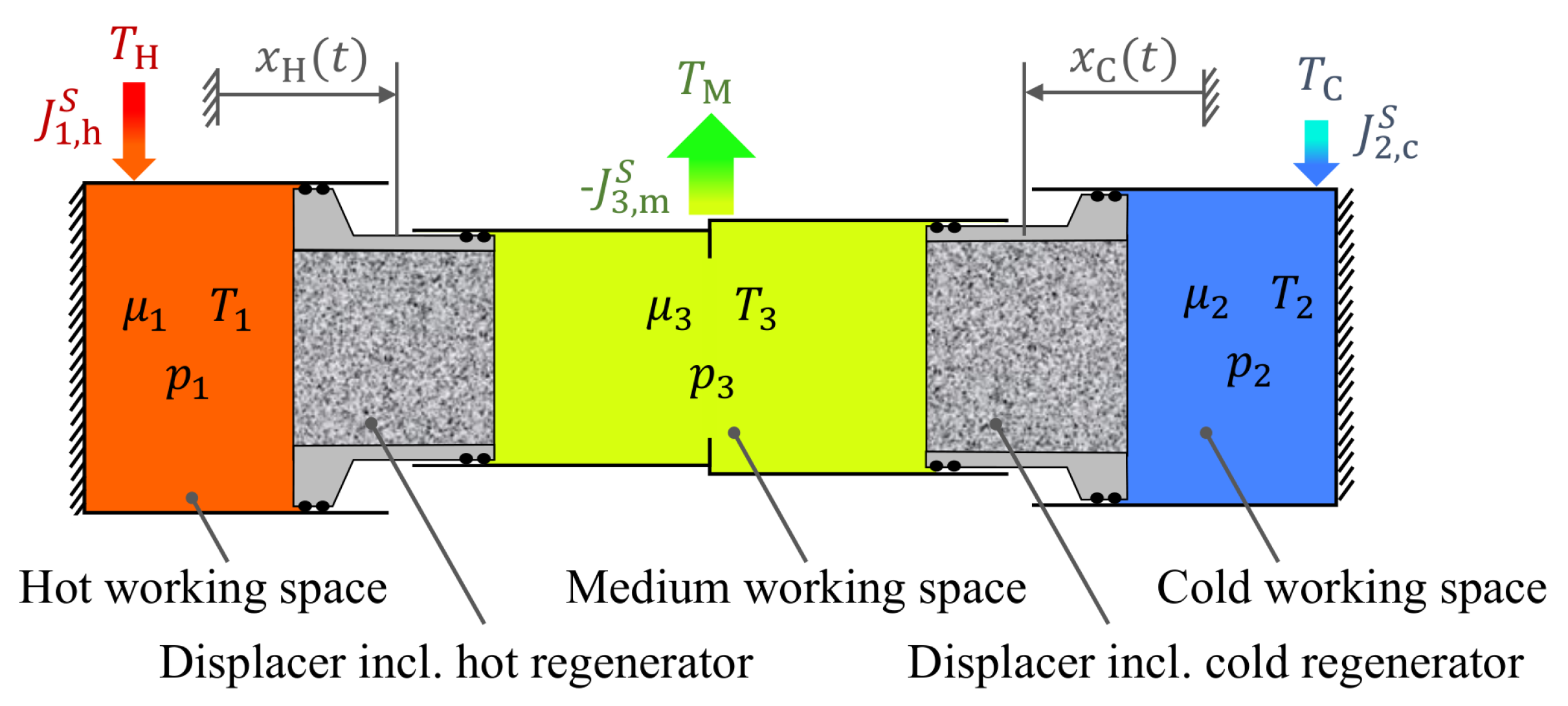
The three working spaces 1, 2, and 3 are displayed by colors indicating their general temperature levels. Red indicates the hot working space, blue the cold one, and green the intermediate one. They are connected to heat exchangers which facilitate the input and output of heat from and into the hot heat source, the cold heat source (the refrigerated space), and the environment. The two displacer pistons move the working fluid between the working spaces, which change their volume periodically. The regenerators are thus subjected to alternating hot and cold fluxes of gas, which leads to the temporary storage of energy as described above.
The piston motion in mechanically-driven Stirling and Vuilleumier machines is usually approximately harmonic due to the crankshaft and connecting rod mechanisms. Here, we will use a pure sinusoidal time dependence with a phase shift between the two pistons.
In this short note, our aim is to study a special feature of Vuilleumier refrigerators that makes them interesting for a particular application area. Obviously, the cooling operation is economically attractive if the driving energy is available as waste heat from other processes. Then the efficiency of the refrigeration process is less important than the cooling power of a given machine. This cooling power depends, of course, on the internal losses occurring in the refrigerator’s operation. Such losses are due to mechanical friction but also due to heat losses and irreversibilities caused by the gas transport through the regenerators. Especially the mechanical friction losses can either be compensated by an auxiliary drive (usually electric) or by designing the Vuilleumier refrigerator such that the pressure differences acting on the pistons lead to the desired forces. The latter solution is, in particular, attractive in situations where the energy input is from waste heat and is thus “free”. In that case, no permanent auxiliary drive is needed.
In order to facilitate such a heat-only operation, one important requirement has however to be met: The piston motion of the displacer pistons must lead to changes of the overall volume inside the Vuilleumier machine, otherwise no power to compensate the losses can be produced. Thus, displacer pistons are needed, which have different cross sections on each side. This feature is indicated in
Figure 1 showing a longitudinal section of the Vuilleumier refrigerator.
The task of our investigation is to establish the conditions needed and in particular the piston areas, which would allow such a heat-only operation of a Vuilleumier refrigerator. We will study this question for the standard harmonic motion and will compare three different design cases, which gain the needed power from the hot displacer, the cold displacer, or from both displacers simultaneously.
2. The Endoreversible Thermodynamics Model
The thermodynamic modeling of Vuilleumier refrigerators needed here goes beyond classical equilibrium approaches. In order to include the main loss terms in a quantitative fashion we use Endoreversible Thermodynamics [
15,
16,
17]. In this approach, the loss terms and the ensuing entropy production are captured quantitatively by viewing the Vuilleumier refrigerators as a network of reversible subsystems which can be described by equilibrium thermodynamics. The irreversibilities are mapped into the interactions between these subsystems, which describe the fluxes of thermodynamic extensities such as volume, entropy, and mol number. Such interactions are characterized by transport laws such as, for instance, Fourier or Newtonian heat conduction. Endoreversible modeling has shown to be an effective tool for describing nonequilibrium systems and has been applied to a variety of systems, among them solar-power-driven systems [
18,
19,
20,
21], thermoelectric [
22,
23] and chemical devices [
24,
25,
26,
27,
28], as well as thermal engines in general [
29,
30,
31,
32,
33]. The endoreversible approach is very useful in the context of optimization studies [
34,
35,
36,
37,
38], as it allows to concentrate on the relevant loss mechanisms in thermal devices and can thus also be used in systems with fluctuating environments [
39,
40,
41]. For this work, it is of particular interest that it has been successfully used in the context of waste heat recovery and recuperation [
38,
42,
43,
44,
45,
46].
The setup of the endoreversibe Vuilleumier refrigerator model used here is presented in
Figure 2. It consists of nine endoreversible subsystems and seven additional reservoirs needed for bookkeeping purposes. The main external interactions are provided by three external (infinite capacity) heat baths H, M, and C with constant temperatures
,
, and
, respectively. For simplicity, we avoid modeling the technical aspects of transporting heat into and out of the device. Instead, we consider the “external” heat sources to be the input sides of the Vuilleumier engine’s heat exchangers. The output sides of these heat exchangers are connected to the respective working spaces—labeled 1, 2, and 3—containing the working gas. Due to the finite heat exchange, the working gas temperatures (
,
, and
) are not identical with the corresponding reservoir temperatures (
,
and
). Nonetheless, the differences are rather small.
The pressure differences between the working spaces can be used to gain mechanical power by the two engines TH and TC. This -power is needed to compensate the frictional losses, which are here accounted for by the bookkeeping reservoir WF. Depending on the engine speed, there may be surplus power or an additional power demand, which is balanced in the bookkeeping reservoirs WTH and WTC separately for each engine. Depending on the engine design, there is possibly a coupling between the two engines, which facilitates a power exchange between them. In a heat-only operation the net cycle average vanishes. As the overall volume of the working spaces changes during a cycle, an infinite volume reservoir E with fixed pressure provides the needed volume fluxes to TH and TC. The regenerators RH and RC between the working spaces are modeled by the two complex interactions rh and rc. These interactions are irreversible, and use two bookkeeping reservoirs each—WRH and SRH for the hot side as well as WRC and SRC for the cold side—which store those energy and entropy amounts during a cycle, which are regenerated.
In our endoreversible model, we will use a linear transport law for the gas transport through the regenerators, i.e., the mol number flux is assumed to be proportional to the pressure difference, with mass transport coefficient being the proportionality constant. The heat fluxes are modeled as Newtonian heat transport with the heat conduction coefficient , which applies to all heat fluxes. Finally, the friction coefficient is used for the frictional losses being quadratic in the volumetric changes on the hot and cold side of each of the two displacer pistons in the refrigerator. These choices capture the main effects of these irreversibilities, but of course more complicated transport laws can be considered if desired.
For the regenerators a variety of endoreversible models exist ranging from ideal regeneration [
47] over the r-regenerator model [
48,
49] to the ES, EE, and EEn models [
50,
51]. Here, we used the r-regenerator model, which captures the regeneration extent by the regeneration coefficient
r. It describes which fraction of the enthalpy difference between the gas states in the two working spaces connected by the regenerator is temporarily stored. The best possible regeneration would take out the whole difference, the worst would take out nothing. As we have two regenerators—a hot and the cold one—and for each of them gas can come from the two connected working spaces, we have four regeneration coefficients
and
for the hot side, and
and
for the cold side. They describe which fraction of the enthalpy of the gas entering working space 1 and working space 3 for the hot side and which fraction of the enthalpy of the gas entering working space 2 and working space 3 for the cold side are taken out. For details see [
49]. When operating the refrigerator, it turns out that the requirement of cyclicity for the regenerators enforces different values for
and
as well as for
and
. As described in [
49], the overall regeneration extent is then given by the respective mean value
The thermal dynamics which unfolds in the Vuilleumier refrigerator depends crucially on the piston motion which we use. Here we will consider the standard harmonic motion. The corresponding volume dynamics in working spaces 1, 2, and 3 is given by
where
is the dead volume,
and
are the respective displacements caused by the diameter of the piston in working spaces 1 and 2 (see
Figure 1),
is the cycle time, and
is the phase shift between the two displacers. Working space 3 is considered as a sum
of two virtual parts
and
facing working spaces 1 and 2 with
3. Heat-Only Operation and Refrigerator Designs
The heat-only operation mode is particularly desirable for applications in which waste heat can be used and a permanent auxiliary power supply is costly. As already discussed, the displacements , , , and cannot have all the same size in heat-only operation. More specifically, for the hot displacer and must be different and/or and for the cold displacer.
In the following, we will compare three different design cases: In the first design, only the hot displacer piston has to provide the needed mechanical power; we will refer to this case as the D1 design. In the second case—the D2 design—all mechanical power comes from the cold displacer piston. Finally we will look at the DA design, in which each of the two pistons provides the mechanical power for its own operation.
On the technical level, heat-only operation of the three design cases is characterized as follows: The DA design requires each cycle average of the two bookkeeping reservoirs WTH and WTC in
Figure 2 to be zero separately, as in this design no power exchange
between the two reservoirs is possible. Thus, for both displacer pistons, mechanical power is neither gained nor lost during operation. For the D1 and D2 designs, this is different: Due to the active power exchange
, only the combined bookkeeping reservoirs WTH and WTC need to balance, and power produced on the hot side can be utilized at the cold side and vice versa.
The obvious question is now which of the three designs is optimal with respect to providing maximal cooling power. In order to prevent an unintended increase or decrease in the overall working volume of the VR during the cooling power optimization, in all three designs the sum of the displacements on the hot and cold side of each displacer piston must remain fixed and equal:
Given this requirement, the volumetric influence of the two pistons are then described by their displacement ratios
and
:
which will be the variables of interest. Below we will investigate how these displacement ratios have to be chosen to ensure a heat-only operation of the Vuilleumier refrigerators. Of particular interest in this context is to what extent the displacement ratios need to be adjusted if the thermodynamic transport parameters
and
of the model are varied.
4. Results
The aim of this exploratory investigation is to determine the cooling power optimal heat-only design of a Vuilleumier refrigerator operating with standard sinusoidal piston movements. In particular we are interested in the question of how the volumetric parameters of the displacer pistons have to be arranged to ensure heat-only operation.
With the endoreversible model developed, we have a set of coupled nonlinear first-order differential equations for the thermodynamic variables describing the gas state in the three working spaces. These can be integrated for the given standard piston motion using different sets of engine variables. However, for each parameter set we need to perform additional adjustment steps to ensure both heat-only operation and the cyclicity of the two regenerators. Therefore, we use two different iterative schemes to establish the desired operation mode.
The refrigerator parameters used in the base case are , , , , , , , , , . Note that the heat conduction coefficient applies to all heat fluxes, and the mass transport coefficient as well as the friction coefficient apply each to all fluxes on the hot and cold side of the refrigerator. These parameters lead to a realistic engine speed range of up to 1000 , in which the cooling power first increases with engine speed, but then decays and becomes negative if the engine speed becomes too large.
Here, our focus is on how the volumetric parameters need to be adjusted in order to reach heat-only operation and how stable the results are for changing regeneration extent. We have analyzed three different regeneration levels: low regeneration with , medium regeneration with , and high regeneration with . First, we present the results for the low regeneration case.
4.1. Low Regeneration
In this low-regeneration scenario the cooling power is quite limited to values below roughly a quarter kW. In
Figure 3, the cooling power is presented as a function of the engine speed for the three different design cases: D1, D2, and DA. It shows that for all three design cases the cooling power first increases and then decreases with engine speed roughly following the shape of an inverted parabola.
The most striking and surprising feature is the clear difference between the three design cases: The D2 design shows a by-far larger cooling power than the two other designs. Its maximum cooling power (at an optimal speed of about 100 ) is more than twice as large as that of the D1 design (at its optimal speed of about 45 ). The DA design leads to cooling power values in between the two other designs. In accordance with the lower maximum cooling power, the DA design, and even more so the D1 design, reaches vanishing cooling power at lower engine speeds: for the DA design at about 140 and for the D1 design at about 85 . An at first sight surprising feature is that the DA design with its largest control possibilities—using both and instead of only one of them—does not lead to the largest cooling power, but one has to note that in this design each piston has to produce the power to compensate its very own friction, and no power exchange between them is allowed.
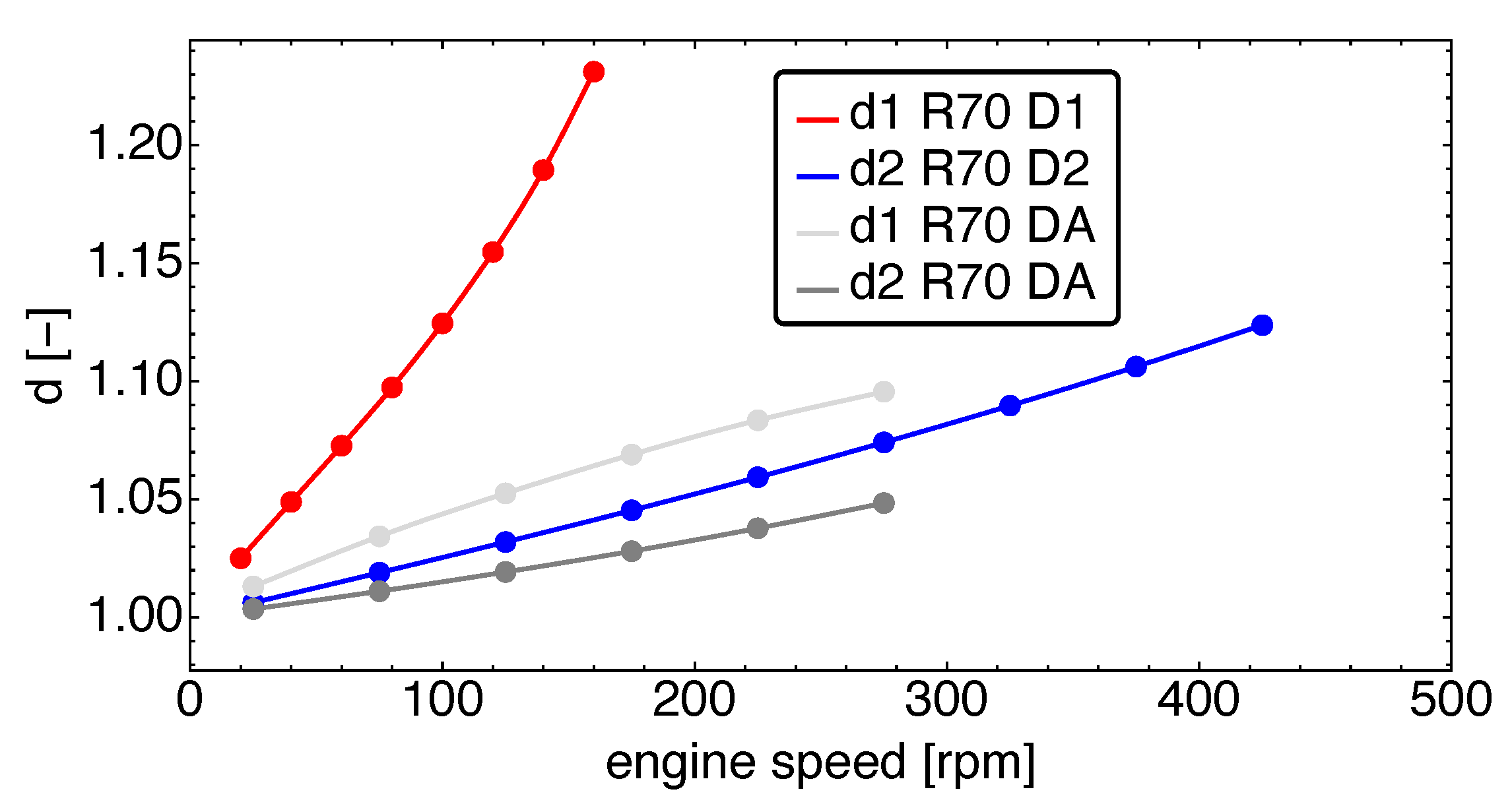
The differences between the three design cases become even more obvious when looking at the displacement ratios
and
shown in
Figure 4. Note the four curves: one for the D1 design, one for the D2 design, and two for the DA design, as in that design both displacement ratios need to be adjusted to ensure compensation of frictional losses for each displacer piston individually.
The displacement ratio for the D1 design stands out with its steep increase with engine speed. It rises to in a nearly linear fashion. This is different for the other two designs: the cold-side displacement ratio for the D2 design shows a much slower increase, which does not even reach at maximum speed for the data shown. For the DA design, the two displacement ratios and also grow more or less linearly, but with a clear distinction between the two: grows faster than and is always approximately twice as large as . Both curves lie below their counterparts for the other designs. Thus, we find that, at least for low regeneration, gaining operational power from the cold side needs a smaller displacement ratio and, additionally, appears to be thermodynamically more efficient than doing so from the hot side.
4.2. Medium Regeneration
In order to evaluate the stability of the results we changed the regeneration extent and here show the results for the medium regeneration case with .
In
Figure 5 the cooling power is addressed as a function of the engine speed. Again the D2 design clearly wins and shows the largest cooling power with a maximum of
at around 200
. In addition, the sequence of the D1 and DA designs remains unaltered, with the D1 design being the worst and the DA design in between. All designs now reach both higher maximum cooling power and larger engine speeds: instead of an engine speed range of 0–200
for the low regeneration case, we here find engine speeds of 0–500
. While the D1 curve still closely follows a parabola shape, the two other curves feature a slower decay towards higher operation speed.
In
Figure 6, the corresponding displacement ratios are presented. Again, the displacement ratio
for the D1 design differs significantly from the displacement ratios for the other designs. It features an increasing behavior, which gets steeper with increasing engine speed. The displacement ratio
is always larger by a factor of two compared to the other displacement ratios. In particular it reaches values above 1.25. Displacement ratio
for the D2 design also features an increase, but with a significantly smaller slope. That behavior is also observed in
for the DA design. In that respect, the behavior of
for the DA design is special, as it shows a decay in its slope and thus the opposite curvature of the other displacement ratios. Nonetheless, both displacement ratios stay below 1.1, indicating that a heat-only operation will not need vastly different piston cross sections on the two ends of the displacer pistons.
4.3. High Regeneration
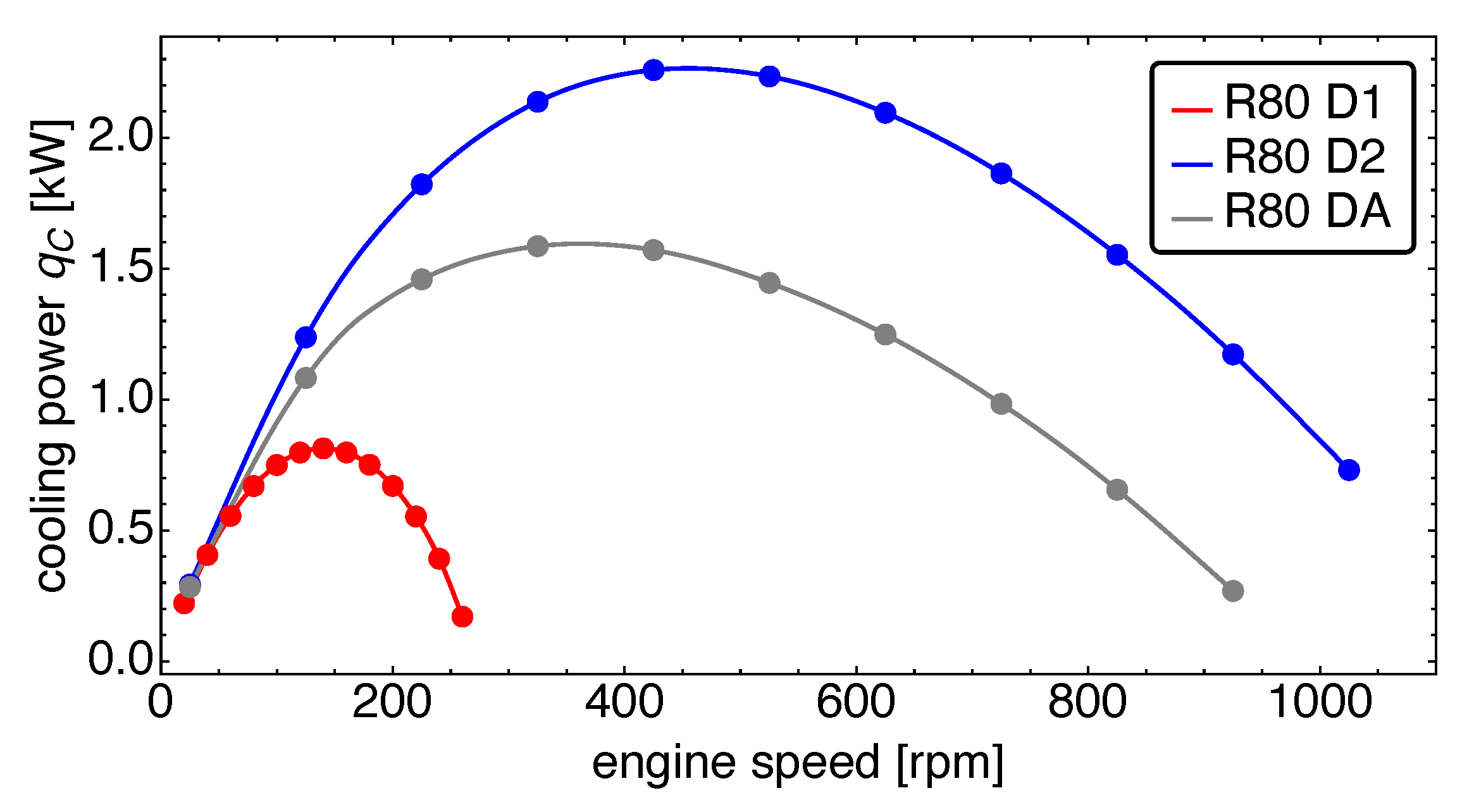
For the high regeneration case, with
, the cooling power is shown in
Figure 7. The engine speeds range now up to more than 1000
for the D2 design. Even though the regeneration coefficient has increased only from
to
by about 15, the maximum cooling power reached for all designs has more than doubled. These maxima are now reached at about 450
for the D2 design and at about 350
for the DA design. The D1 design again performs much poorer with a maximum cooling power of roughly a third of the cooling power of the D2 design. We also note that the increase in cooling power with operation speed is clearly steeper for the D2 and DA designs, while the D1 design still looks quite symmetric in its increase and decrease with respect to its maximum.
In
Figure 8, the corresponding displacement ratios are presented. Interestingly, the D1 and the D2 designs both reach up to values closely below 1.4. This is different for the DA design, for which both displacement ratios stay lower. While
reaches values up to 1.25,
flattens out at values around 1.1. This seems surprising, as with increasing engine speed also for the DA design the displacer piston suffers losses from the friction with increasing engine speed, but even though the two pistons have no power exchange, there is of course still the thermodynamic coupling of the expansion and compression phases with the changes in the pressure differences.
4.4. Sensitivity of the Results on the Mass Transport Coefficient
In order to give the reader an impression on how general the above results are, we performed a sensitivity analysis of our results with respect to the two important thermodynamic transport coefficients
and
. For this purpose we varied both coefficients separately by 30 percentage points starting at 85% and increased them in steps of five percentage points up to 115%. We here restrict ourselves to data for medium regeneration. In that way, one obtains curves similar in shape to those shown for the base case in
Figure 5. For each of these curves, we determined the maximum cooling power
and its corresponding engine speed.
In
Figure 9, the rescaled cooling power
is shown as function of the rescaled mass transport coefficient
, where
is the maximum cooling power for the base case. Note that below we will always use rescaled values for ease of comparison. The figure shows that the cooling power changes only by one digit percentage values over the full 30% rage of the mass transport coefficient. The largest changes occur for the D1 design, which exhibits relative changes larger by roughly a factor of four compared to the other designs. An interesting feature is that for the D1 and DA designs the cooling power increases with the mass transport coefficient, while it decays for the D2 design.
In
Figure 10, the rescaled engine speed at maximum cooling power is shown as function of the rescaled mass transport coefficient
. Overall, the relative change of the engine speed at maximum cooling power behaves similar to the cooling power with the decreasing engine speed for the D2 design and increasing engine speed for the other two designs. The size of the relative changes is also in the one digit percentage range.
Finally we turn to the relative changes in the displacement ratios. These are shown in
Figure 11. All rescaled displacement ratios decay with increasing rescaled mass transport coefficient
. The size of the relative change is less than one percent for the investigated range of mass transport coefficients. This already shows that the obtained results are very insensitive to those parameter variations.
4.5. Sensitivity of the Results on the Heat Transport Coefficient
We now turn to the sensitivity of the results with respect to variations in the heat transport coefficient . As the mass transport coefficient, it was separately changed by 30 percentage points starting at 85% and increased in steps of five percentage points up to 115%.
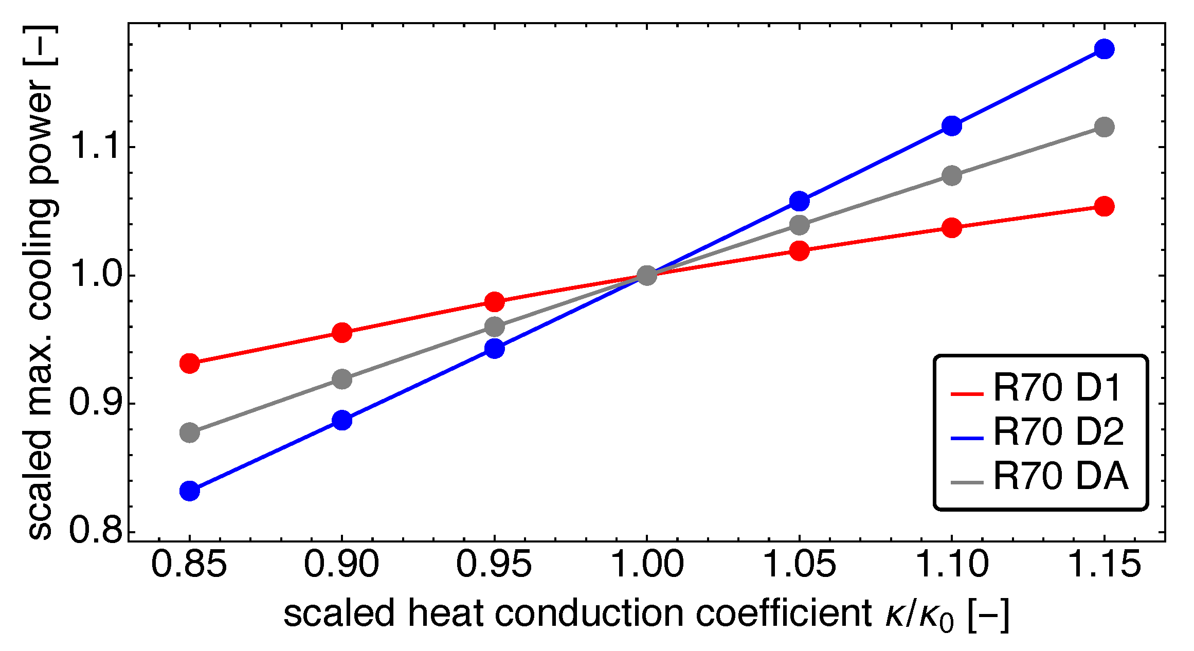
In
Figure 12, the rescaled cooling power
is shown as function of the rescaled heat transport coefficient
. Here, the rescaled maximum cooling power increases for all three designs with increasing heat conductance. That is not surprising as increased heat conductance means faster turnover of energy and thus also larger cooling power. Note that the increase of the cooling power for the D2 design is on the order of nearly 20% for a 15% increase in
compared to the base case.
In
Figure 13, the corresponding rescaled engine speed at maximum cooling power as function of the rescaled heat transport coefficient
is presented. It shows for all three designs that the rescaled engine speed at maximum cooling power increases as well, with increasing heat conductance showing similar variation sizes. Again, the D2 design exhibits the largest changes.
The resulting changes in the displacement ratios are presented in
Figure 14. As for variations in the mass transport coefficient, the relative changes in the displacement ratios with the heat transport coefficient are in the one percent range with those of the D2 design being the largest. The rescaled displacement ratios increase more or less linearly with the rescaled heat transport coefficient
.
Overall, both sensitivity investigations have shown that the main findings for the base case parameters do also apply, if the mass and the heat transport coefficients are varied in considerable range around the base case.
5. Discussion and Summary
In this short note we present our findings on the cooling power optimal design of Vuilleumier refrigerators for heat-only operation. In particular, we investigated three competing designs: The D1 design, in which the hot displacer piston features two different volume displacements in the hot and medium working space thus providing the mechanical power needed for the entire refrigerator; the D2 design, in which the cold displacer piston provides the mechanical power needed for the entire refrigerator; and the DA design, where both displacer pistons each provide their own mechanical power. The surprising result we found is that the D2 design leads by far to the highest cooling power, followed by the DA design and the D1 design, which provide less than half the cooling power with an otherwise unchanged refrigerator. Even the DA design, which seemed to promise high performance with its increased optimizing potential due to the possible adjustment of both piston displacement ratios only provides approximately
of the cooling power compared to the D2 design. We caution the reader that these results of course depend on the parameter values chosen. The sensitivity investigations we performed for the medium regeneration extent, however, support that our results are very stable against variations of the two relevant thermodynamic transport coefficients. Moreover, it is obvious that future work must address the question of to what extent the results change if, in particular, different transport parameters are allowed for each individual flux present in the refrigerator. Nonetheless, this exploratory investigation shows that surprising features for the heat-only operation of Vuilleumier refrigerators can occur, which might have impact on the design of future devices operating on waste heat. Finally, we would like to mention that work carried out on the optimization of Stirling engines [
52,
53,
54,
55,
56,
57,
58] of course provides interesting ideas to further optimize Vuilleumier refrigerators, and, in particular, those using heat-only-driven operation.


