
Capturing a Space Target Using a Flexible Space Robot


Abstract
:1. Introduction
2. Dynamic Model of Space Robot
3. Contact Model
3.1. Contact Force
3.2. Contact Detection and Penetration Depth Calculating
4. Controller Design for the Manipulator
5. Numerical Simulations
- (1)
- (2)
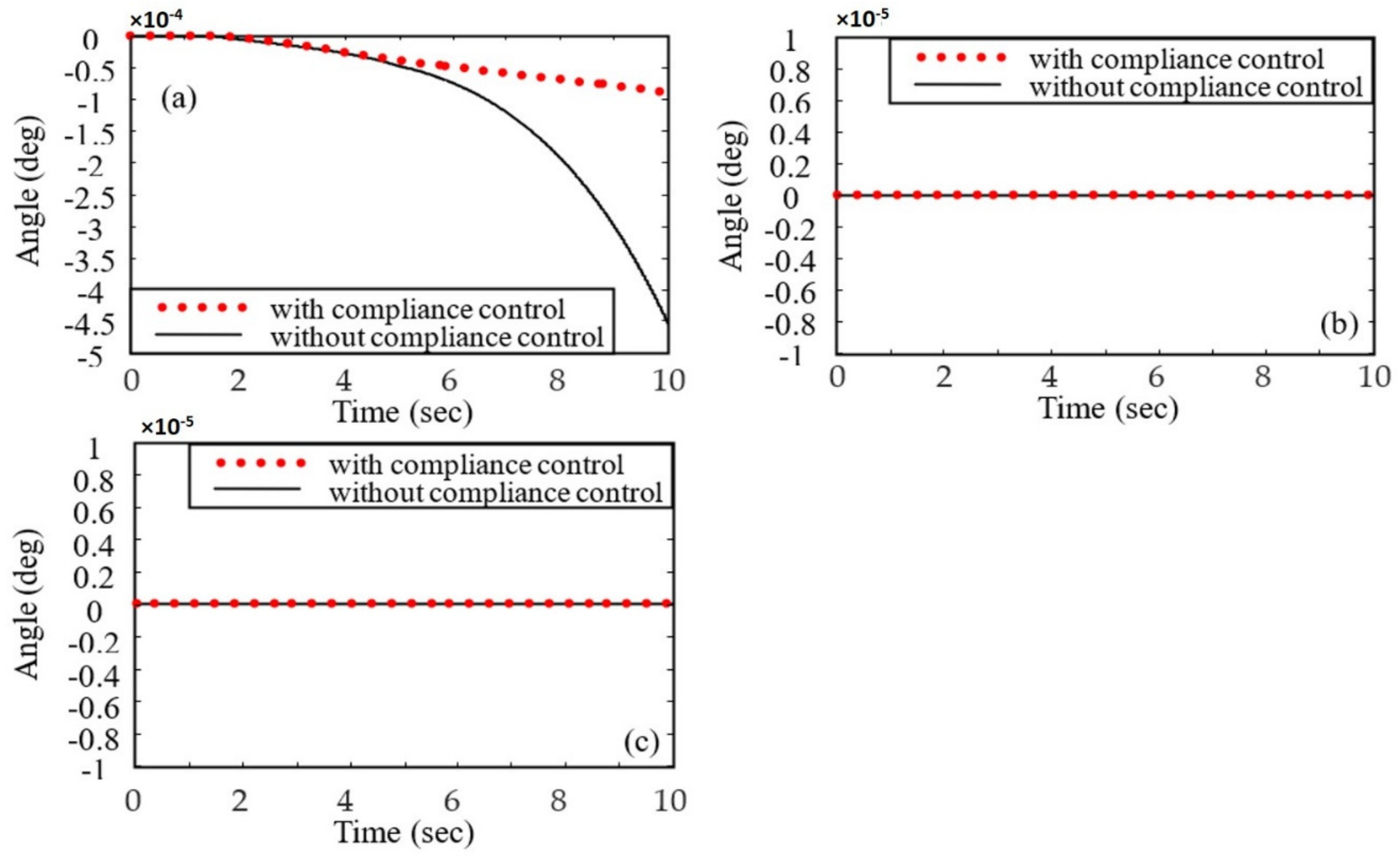
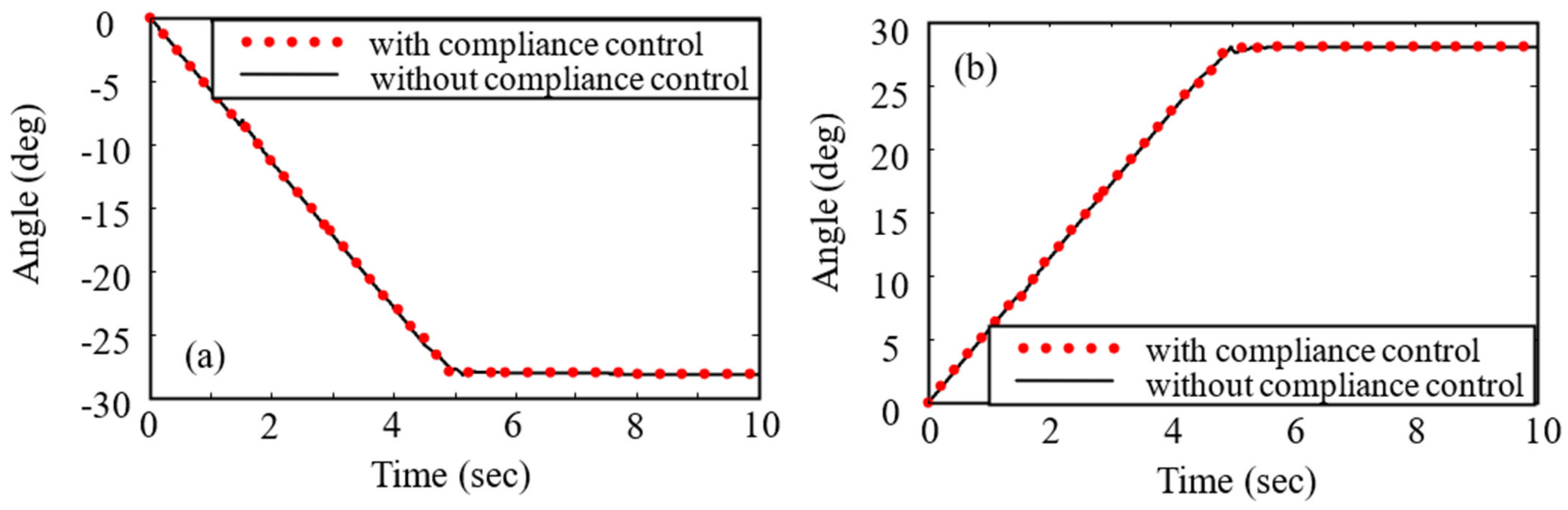
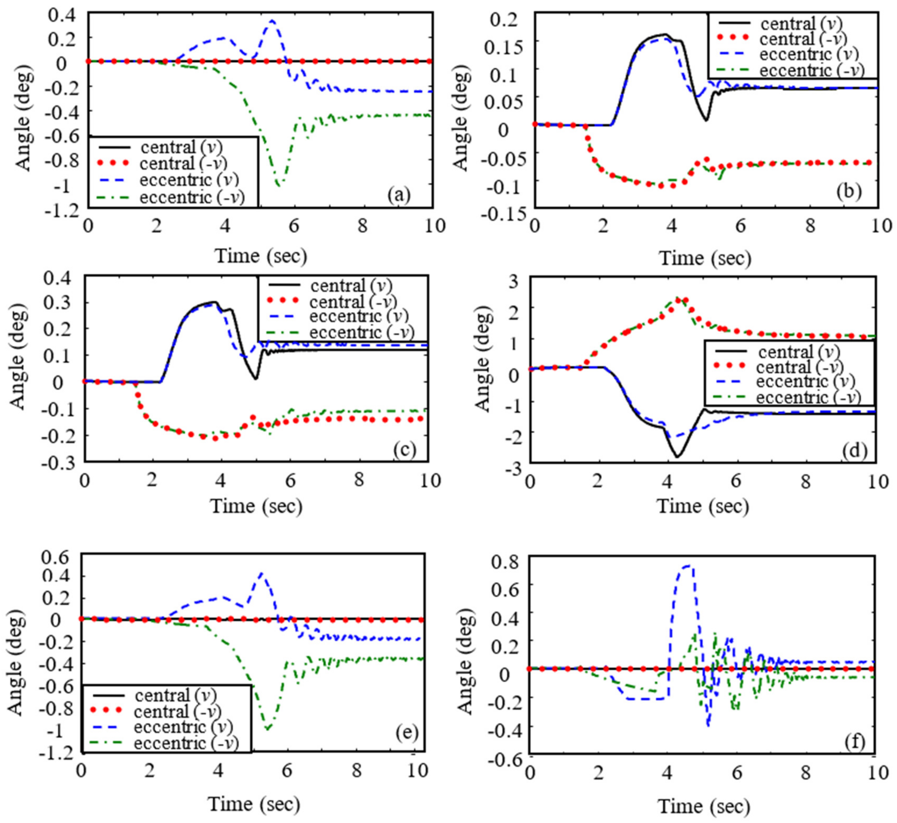
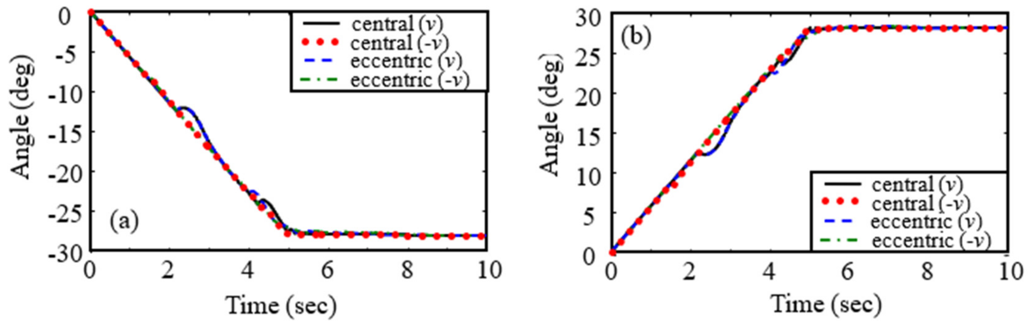
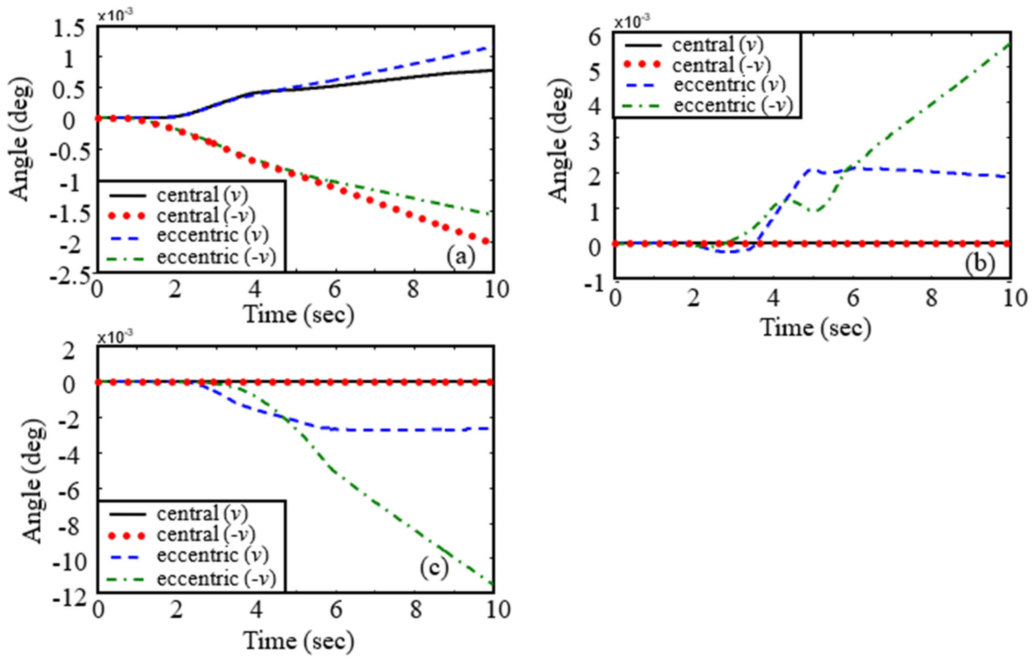
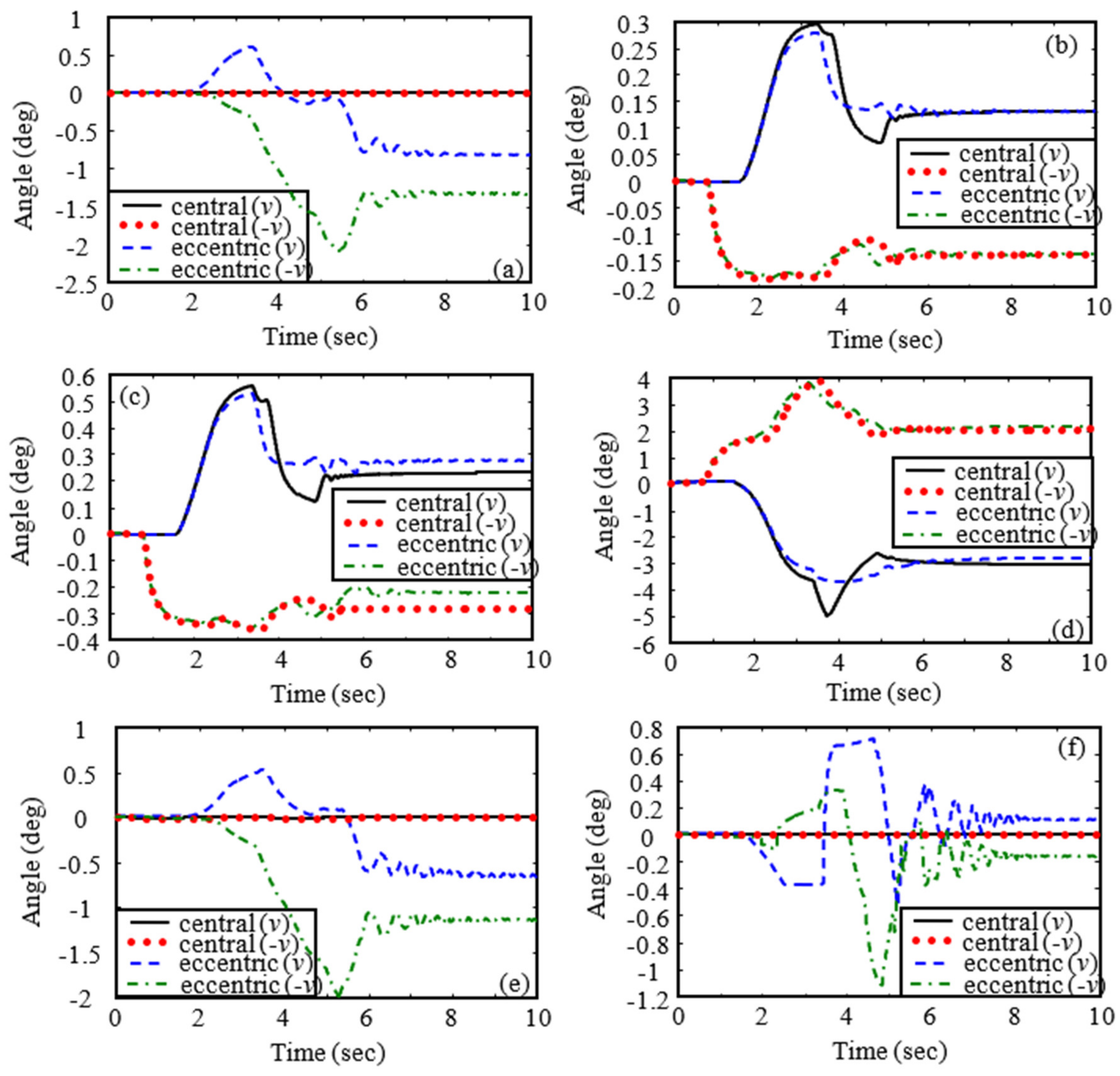
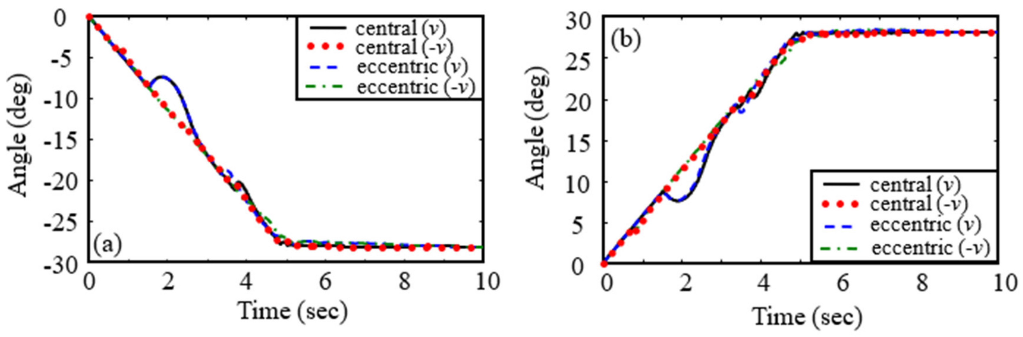
- From Figure 11 and Figure 15, we can observe that the controller designed in this paper can stabilize the motion of joint angles of the manipulator. It is observed from Figure 11a,e,f and Figure 15a,e,f that eccentric impact could cause the joint angle change of the manipulator in the Axis 1, Axis 5, and Axis 6 directions, while central impact could not.
- (3)
- (4)
- (5)
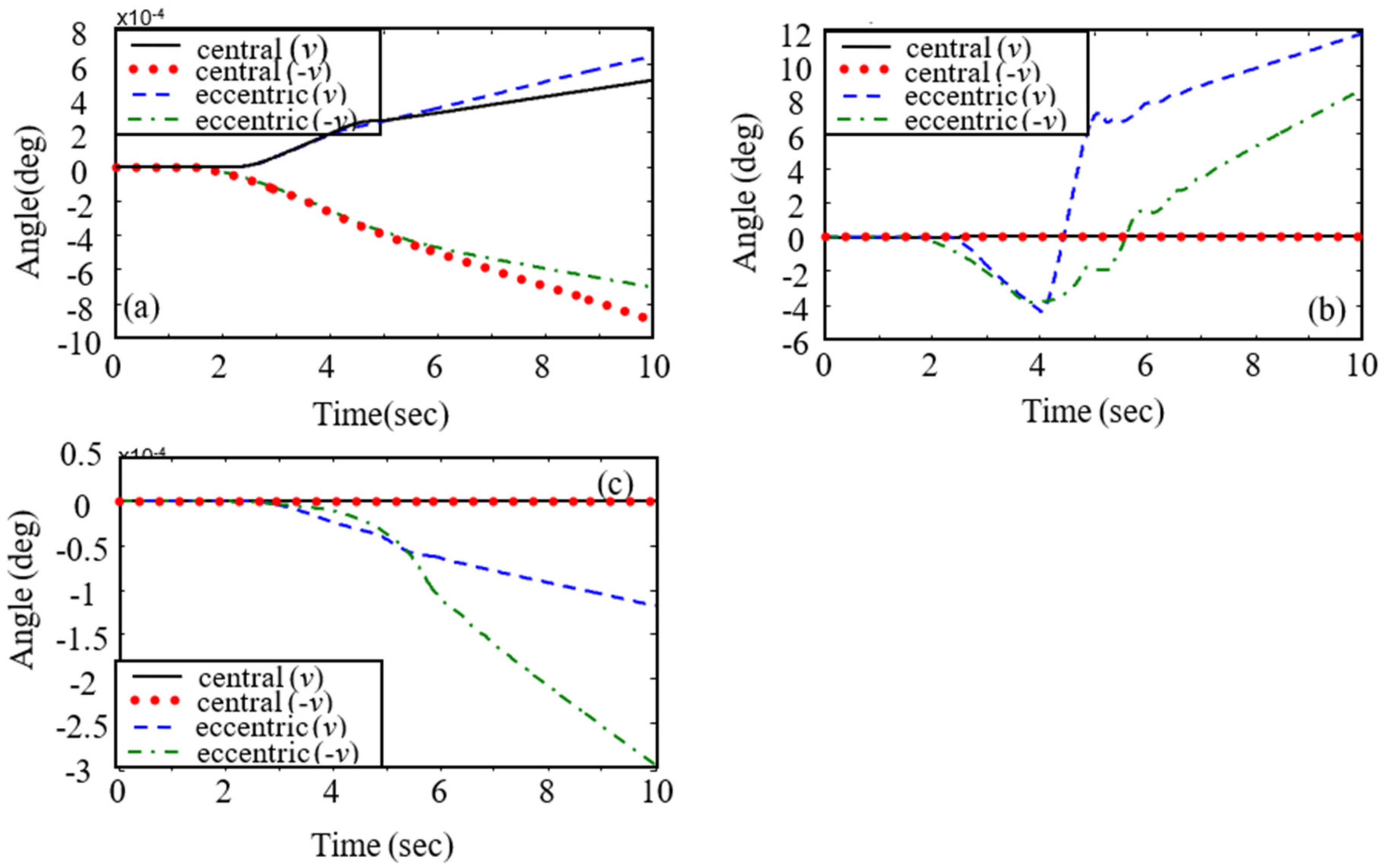
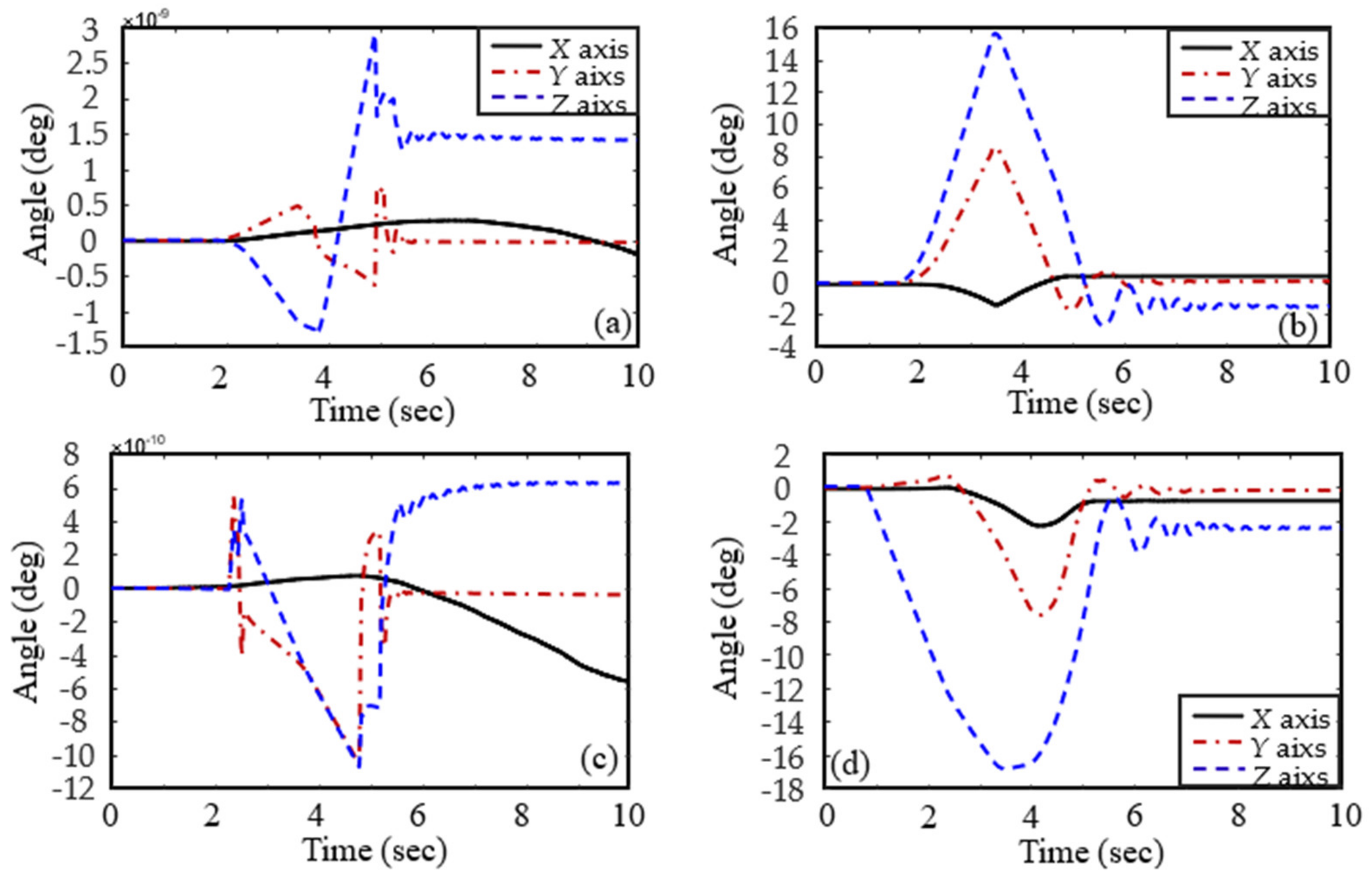
- As depicted in Figure 18 and Figure 19, we can observe that eccentric impact causes obvious attitude change of B8, meaning B8 is tumbling, but central impact cannot. Meanwhile, it is observed that the attitude evolution trend is changed several times in eccentric impact cases, which shows that there are multiple instances of contact during capturing. Moreover, it demonstrates that the tumbling motion of the target object makes the capturing operation complicated.
- (6)
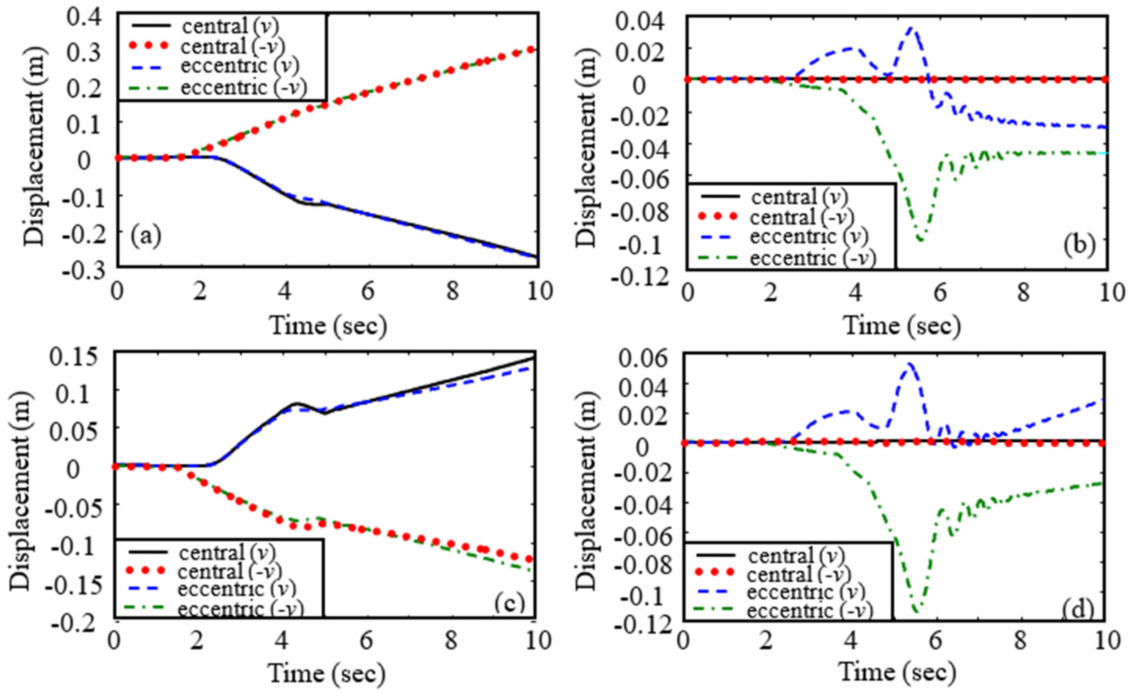
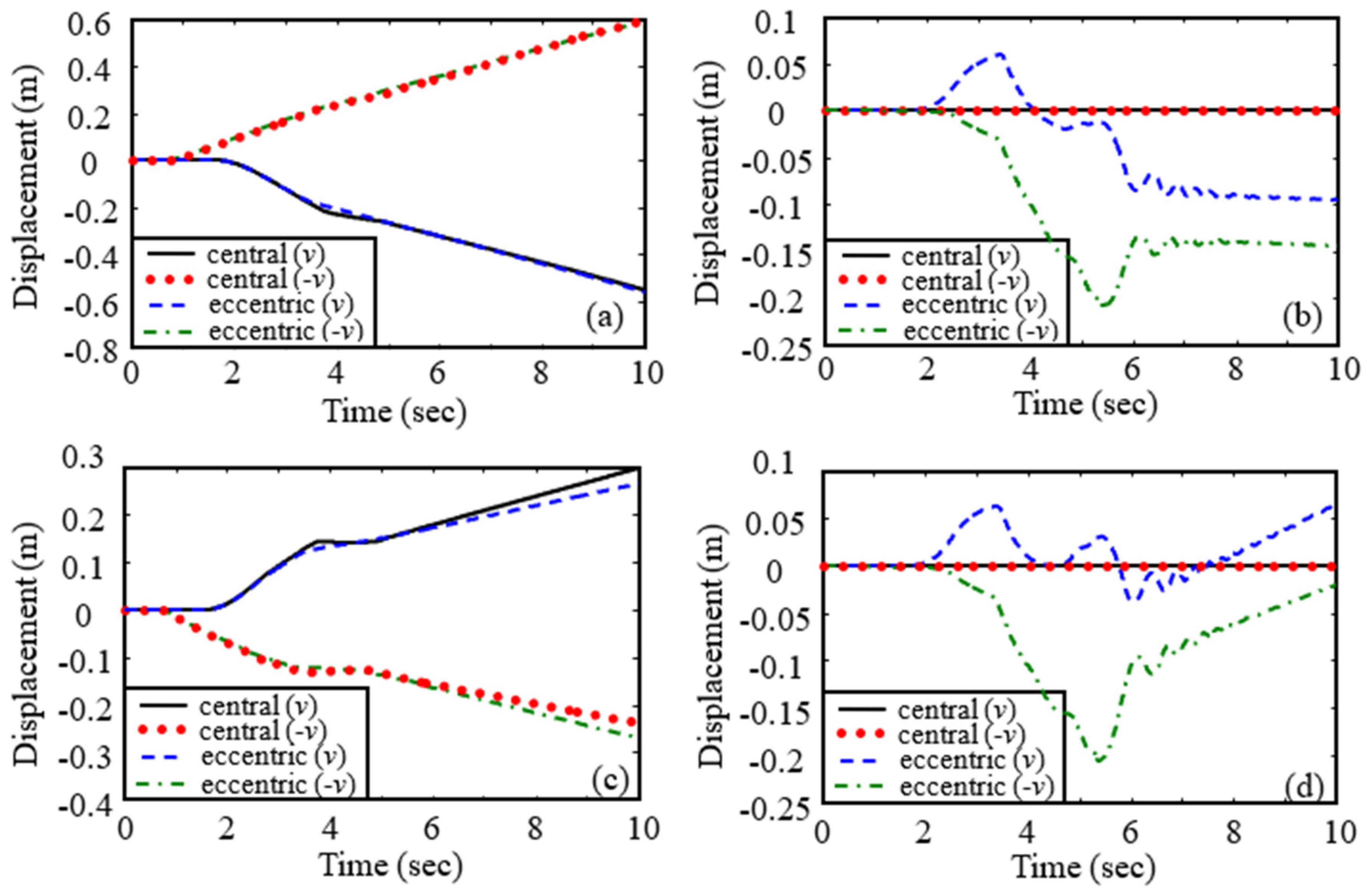
- Figure 10, Figure 11, Figure 12, Figure 13, Figure 14, Figure 15, Figure 16, Figure 17, Figure 18 and Figure 19 show the impact on the robot system caused by capturing when the target cylinder moves towards the manipulator are more significant than those when the target moves away from the manipulator.
6. Concluding Remark
Author Contributions
Funding
Institutional Review Board Statement
Informed Consent Statement
Data Availability Statement
Acknowledgments
Conflicts of Interest
References
- Fukushima, Y.; Inaba, N.; Oda, M. Capture and berthing experiment of a massive object using ETS7 space robot. In Proceedings of the AIAA Astrodynamics Specialist Conference, Denver, CO, USA, 14–17 August 2000; pp. 635–638. [Google Scholar]
- Friend, R.B. Orbital Express program summary and mission overview. In Proceedings of the SPIE Sensors and Systems for Space Applications II, Orlando, FL, USA, 17–18 April 2008; pp. 695801–695803. [Google Scholar]
- Van, V.J.; Sharf, I.; Ma, O. Experimental validation of contact dynamics simulation of constrained robotic tasks. Int. J. Robot. Res. 2000, 19, 1203–1217. [Google Scholar]
- Wee, L.B.; Walker, M.W. On the dynamics of contact between space robots and configuration control for impact minimization. IEEE Trans. Robot. Autom. 1993, 9, 581–591. [Google Scholar]
- Cyril, X.; Jaar, G.J.; Misra, A.K. The effect of payload impact on the dynamics of a space robot. In Proceedings of the IEEE/RSJ International Conference on Intelligent Robots and Systems, Yokohama, Japan, 26–30 July 1993; pp. 2070–2075. [Google Scholar]
- Cyril, X.; Misra, A.K.; Ingham, M.; Jaar, G.J. Postcapture dynamics of a spacecraft-manipulator-payload system. J. Guid. Control Dyn. 2000, 23, 95–100. [Google Scholar] [CrossRef]
- Yoshida, K.; Sashida, N.; Kurazume, R.; Umetani, Y. Modeling of collision dynamics for space free-floating links with extended generalized inertia tensor. In Proceedings of the IEEE International Conference on Robotics and Automation, Nice, France, 12–14 May 1992; Volume 1, pp. 899–904. [Google Scholar]
- Yoshida, K.; Sashida, N. Modeling of impact dynamics and impulse minimization for space robots. In Proceedings of the IEEE/RSJ International Conference on Intelligent Robots and Systems, Yokohama, Japan, 26–30 July 1993; Volume 3, pp. 2064–2069. [Google Scholar]
- Yoshida, K.; Mavroidis, C.; Dubowsky, S. Impact dynamics of space long reach manipulator. In Proceedings of the IEEE International Conference on Robotics and Automation, Minneapolis, MN, USA, 22–28 April 1996; pp. 1909–1916. [Google Scholar]
- Yoshida, K.; Nakanishi, H. Impedance matching in capturing a satellite by a space robot. In Proceedings of the IEEE/RSJ International Conference on Intelligent Robots and Systems, Las Vegas, NV, USA, 27–31 October 2003; Volume 4, pp. 3059–3064. [Google Scholar]
- Yoshida, K.; Nakanishi, H.; Ueno, H.; Inaba, N.; Nishimaki, T.; Oda, M. Dynamics, control and impedance matching for robotic capture of a non-cooperative satellite. Adv. Robot. 2004, 18, 175–198. [Google Scholar] [CrossRef]
- Yoshida, K.; Dimitrov, D.; Nakanishi, H. On the capture of tumbling satellite by a space robot. In Proceedings of the IEEE/RSJ International Conference on Intelligent Robots and Systems, Beijing, China, 9–15 October 2006; pp. 4127–4132. [Google Scholar]
- Shibli, M.; Aghili, F.; Su, C.-Y. Modeling of a free-flying space robot manipulator in contact with a target satellite. In Proceedings of the IEEE Conference on Control Applications, Toronto, ON, Canada, 28–31 August 2005; pp. 559–564. [Google Scholar]
- Shibli, M.; Su, C.-Y.; Aghili, F. Adaptive inverse dynamics control of free-flying space robot contact with a target satellite: A Hubble space telescope case. In Proceedings of the IEEE Canadian Conference on Electrical and Computer Engineering, Ottawa, ON, Canada, 7–10 May 2006; pp. 1275–1278. [Google Scholar]
- Matunaga, S.; Kanzawa, T.; Ohkami, Y. Rotational motion-damper for the capture of an uncontrolled floating satellite. Control Eng. Pract. 2001, 9, 199–205. [Google Scholar] [CrossRef]
- Uyama, N.; Hirano, D.; Nakanishi, H.; Nagaoka, K.; Yoshida, K. Impedance-based contact control of a free-flying space robot with respect to coefficient of restitution. In Proceedings of the IEEE/SICE International Symposium on System Integration (SII), Kyoto, Japan, 20–22 December 2011; pp. 1196–1201. [Google Scholar]
- Uyama, N.; Nakanishi, H.; Nagaoka, K.; Yoshida, K. Impedance-based contact control of a free-flying space robot with a compliant wrist for non-cooperative satellite capture. In Proceedings of the IEEE/RSJ International Conference on Intelligent Robots and Systems, Vilamoura-Algarve, Portugal, 7–12 October 2012; pp. 4477–4482. [Google Scholar]
- Thai, C.; Nguyen, H.; Inna, S. Capture of spinning target with space manipulator using magneto rheological damper. In Proceedings of the AIAA Guidance, Navigation, and Control Conference, Toronto, ON, Canada, 2–5 August 2010; p. 7753. [Google Scholar]
- Xu, W.F.; Liang, B.; Li, C.; Liu, Y.; Wang, X.Q. A modelling and simulation system of space robot for capturing non-cooperative target. Math. Comp. Model. Dyn. 2009, 15, 371–393. [Google Scholar] [CrossRef]
- Xu, W.F.; Meng, D.S.; Chen, Y.Q.; Qian, H.H.; Xu, Y.S. Dynamics modeling and analysis of a flexible-base space robot for capturing large flexible spacecraft. Multibody Syst. Dyn. 2014, 32, 357–401. [Google Scholar] [CrossRef]
- Liu, X.-F.; Li, H.-Q.; Chen, Y.-J.; Cai, G.-P.; Wang, X. Dynamics and control of capture of a floating rigid body by a spacecraft robotic arm. Multibody Syst. Dyn. 2015, 33, 315–332. [Google Scholar] [CrossRef]
- Yu, Z.-W.; Liu, X.-F.; Cai, G.-P. Dynamics modeling and control of a 6-DOF space robot with flexible panels for capturing a free floating target. Acta Astronaut. 2016, 128, 560–572. [Google Scholar] [CrossRef]
- Nishida, S.; Yoshikawa, T. Space debris capture by a joint compliance controlled robot. In Proceedings of the IEEE/ASME International Conference on Advanced Intelligent Mechatronics, Kobe, Japan, 20–24 July 2003; Volume 1, pp. 496–502. [Google Scholar]
- Nishida, S.; Yoshikawa, T. Capture and motion braking of space debris by a space robot. In Proceedings of the International Conference on Control, Automation and Systems, Seoul, Korea, 17–20 October 2007; pp. 706–711. [Google Scholar]
- Nishida, S.-I.; Kawamoto, S.; Okawa, Y.; Terui, F.; Kitamura, S. Space debris removal system using a small satellite. Acta Astronaut. 2009, 65, 95–102. [Google Scholar] [CrossRef]
- Nishida, S.; Kawamoto, S. Strategy for capturing of a tumbling space debris. Acta Astronaut. 2011, 68, 113–120. [Google Scholar] [CrossRef]
- Liu, J.; Huang, Q.; Yang, T.; Deng, T. Compliant control of a space robot with multi arms for capturing large tumbling target. In Proceedings of the IEEE International Conference on Mechatronics and Automation, Takamatsu, Japan, 6–9 August 2017; pp. 1859–1864. [Google Scholar]
- Liu, X.-F.; Cai, G.-P.; Wang, M.-M.; Chen, W.-J. Contact control for grasping a non-cooperative satellite by a space robot. Multibody Syst. Dyn. 2020, 50, 119–141. [Google Scholar] [CrossRef]
- Liu, X.F.; Zhang, X.Y.; Chen, P.C.; Cai, G.P. Hybrid control scheme for grasping a non-cooperative tumbling satellite. IEEE Access 2020, 8, 54963–54978. [Google Scholar] [CrossRef]
- Stolfi, A.; Gasbarri, P.; Sabatini, M. A combined impedance-PD approach for controlling a dual-arm space manipulator in the capture of a non-cooperative target. Acta Astronaut. 2017, 139, 243–253. [Google Scholar] [CrossRef]
- Stolfi, A.; Gasbarri, P.; Sabatini, M. A parametric analysis of a controlled deployable space manipulator for capturing a non-cooperative flexible satellite. Acta Astronaut. 2018, 148, 317–326. [Google Scholar] [CrossRef]
- Zarafshan, P.; Moosavian, S. Fuzzy tuning control approach to perform cooperative object manipulation by a rigid–flexible multibody robot. Multibody Syst. Dyn. 2017, 40, 213–233. [Google Scholar] [CrossRef]
- Zarafshan, P.; Larimi, R.; Moosavian, S.; Siciliano, B. Which impedance strategy is the most effective for cooperative object manipulation? Ind. Robot 2017, 44, 198–209. [Google Scholar] [CrossRef]
- Liu, X.F.; Li, H.Q.; Wang, J.S.; Cai, G.P. Dynamics analysis of flexible space robot with joint friction. Aerosp. Sci. Technol. 2015, 47, 164–176. [Google Scholar] [CrossRef]
- Johnson, K.L. Contact Mechanics; Cambridge University Press: Cambridge, UK, 1984. [Google Scholar]
- Ericson, C. Real-Time Collision Detection; Elsevier: Amsterdam, The Netherlands, 2005. [Google Scholar]


| Body | Mass (kg) | Ixx (kg·m2) | Iyy (kg·m2) | Izz (kg·m2) | EI (N·m2) | GJ (N·m2) | EA (N) |
|---|---|---|---|---|---|---|---|
| B1 | 1.0179 × 10⁵ | 5.0894 × 10⁶ | 4.9113 × 10⁶ | 4.9113 × 10⁶ | |||
| B2 | 138 | 0.399 | 471.82 | 471.82 | 4.04 × 10⁶ | 2.040 × 10⁶ | 2.8 × 10⁹ |
| B3 | 85.06 | 0.4 | 348.01 | 348.01 | 2.81 × 10⁶ | 1.417 × 10⁶ | 1.2 × 10⁹ |
| B4 | 8 | 0.2 | 0.76 | 0.76 | |||
| B5 | 41 | 0.2 | 5.02 | 5.02 | |||
| B6 | 12.25 | 0.163 | 0.136 | 0.2759 | |||
| B7 | 6.125 | 0.082 | 0.0068 | 0.0767 | |||
| B8 | 480.35 | 1.18 | 0.7 | 0.7 |
Publisher’s Note: MDPI stays neutral with regard to jurisdictional claims in published maps and institutional affiliations. |
© 2022 by the authors. Licensee MDPI, Basel, Switzerland. This article is an open access article distributed under the terms and conditions of the Creative Commons Attribution (CC BY) license (https://creativecommons.org/licenses/by/4.0/).
Share and Cite
Liu, X.-F.; Zhang, X.-Y.; Cai, G.-P.; Chen, W.-J. Capturing a Space Target Using a Flexible Space Robot. Appl. Sci. 2022, 12, 984. https://doi.org/10.3390/app12030984
Liu X-F, Zhang X-Y, Cai G-P, Chen W-J. Capturing a Space Target Using a Flexible Space Robot. Applied Sciences. 2022; 12(3):984. https://doi.org/10.3390/app12030984
Chicago/Turabian StyleLiu, Xiao-Feng, Xiao-Yu Zhang, Guo-Ping Cai, and Wu-Jun Chen. 2022. "Capturing a Space Target Using a Flexible Space Robot" Applied Sciences 12, no. 3: 984. https://doi.org/10.3390/app12030984
APA StyleLiu, X.-F., Zhang, X.-Y., Cai, G.-P., & Chen, W.-J. (2022). Capturing a Space Target Using a Flexible Space Robot. Applied Sciences, 12(3), 984. https://doi.org/10.3390/app12030984