1. Introduction
Wireless headphones have become one of the most prevailing wearable personal devices in recent years. For most high-qualified headphones, an active noise control (ANC) module is generally equipped as a standard configuration, which is designed to reduce the outside noise and offer a better listening environment. The control strategies for ANC headphones can be classified into the feedforward, the feedback and the hybrid ones, among which the feedback control strategy has the longest history of research and application and is discussed in the rest of this paper.
In feedback ANC headphones, the noise reduction (NR) within the low frequency band is generally realized at the price of noise enhancements at other frequencies, which is well-known as the waterbed effect [
1] in the literature. Thus, the basic principle to design a feedback controller for ANC headphones is to maximize the NR performance within the low frequency band while maintain the robust stability of the system and restricting the noise enhancement at high frequencies. Meanwhile, the NR bandwidth is restricted by the delay of the open-loop plant response [
1], which indicates that the feedback microphone should be placed near the speaker and the latency of the controller should also be minimized.
The feedback controllers of ANC headphones were first implemented with analog circuits. Different design procedures were proposed by Bai et al. [
2], Pawełczyk [
3] and Hu et al. [
4,
5], respectively. However, the main drawback of an analog ANC controller is the uncertainty of its frequency response (FR), which is mainly caused by the uncertainty of the capacitors used in the circuits. In massive production, the actual capacitance would deviate from its nominal value (up to 5%, 10% or even 20%). As a result, the actual NR performance would not be in accordance and the averaged NR performance would also be limited.
Compared with analog circuits, digital controllers have the advantages of high consistency as well as high flexibility. Rafaely et al. [
6] proposed an H2/H∞ design method for feedback controllers, where a convex programming problem using FIR filters is established with the help of internal model control (IMC). Zhang et al. [
7] proposed an intuitive approach where the feedback controller is first designed in frequency domain and then approximated by an FIR filter. With the IMC structure, the feedback controller could even be made fully adaptive [
8]. However, the modeling errors of the secondary path deteriorate the stability bound of the system [
9] and the waterbed effect should also be taken care of [
10]. A semi-adaptive strategy [
11] can also be considered with a digital controller, where the controller coefficients are selected from a set of pre-trained fixed filters according to the current noise environment.
The major problem of a digital controller is that an extra delay is introduced, which could be reduced by a higher sampling frequency. However, the computational burden would be greatly enhanced with the above methods where FIR controllers are used. Specially designed very large scale integration circuits [
12] might be necessary in this case. This problem could be alleviated with the usages of a warped FIR filter [
13] or cascade biquad filters [
14], the latter of which is particularly advantageous for commercial products since the controller cost could be greatly lowered and the battery lifetime could also be lengthened. The effectiveness of cascade biquad feedback controllers has been confirmed in [
14], in which genetic algorithm and Nelder–Mead simplex methods are combined to search the optimal parameters of the feedback controller. To the best of the authors’ knowledge, cascade biquad filters have been widely used as controllers for commercial ANC headphone products in recent years.
In the works mentioned above, the NR performance was generally evaluated by the feedback microphone. As the feedback microphone should be placed near the speaker, the residual error signal might be different from the one perceived by the human ear. In fact, if the FRs of the primary and the secondary paths corresponding to the human ear show large differences with respect to the feedback microphone, which is called FR mismatches in the rest of this paper, the actual NR performance would deteriorate even if the controller were designed to be optimal for the feedback microphone [
15]. In principle, this problem could be alleviated by virtual sensing methods [
16]. Pawelczyk [
17] and Benois et al. [
18] tried to estimate the error signal at the eardrum and use it to construct the feedback control, where it is assumed that the primary paths are the same for the feedback microphone and the eardrum. However, just as pointed in [
15], the error signal at the eardrum corresponds to a larger delay of the plant so that the NR bandwidth would be reduced, even if all models are accurate enough. Liang et al. [
15] proposed a two-stage hybrid method where the feedback controller is designed using the conventional method, but an extra feedforward controller is utilized to compensate the performance degradation caused by FR mismatches of the primary and the secondary paths.
In this paper, FR mismatches of both the primary and the secondary paths are addressed on the optimization problem of the feedback controller for ANC headphones. The feedback loop is constructed directly with the feedback microphone and the extra filters of the virtual sensing techniques are avoided. Instead, an optimization problem is established in which the NR performance is evaluated at the human ear. Cascade biquad filters are used as the feedback controller which is in accordance with real applications. As the optimization problem is non-convex, a differential evolution (DE) algorithm [
19] is used to find the optimal solution, whose efficiency has been confirmed by the optimization of the feedforward controllers [
20]. Finally, experiments are carried out through which the effectiveness of the proposed method is validated.
2. Problems with FR Mismatches
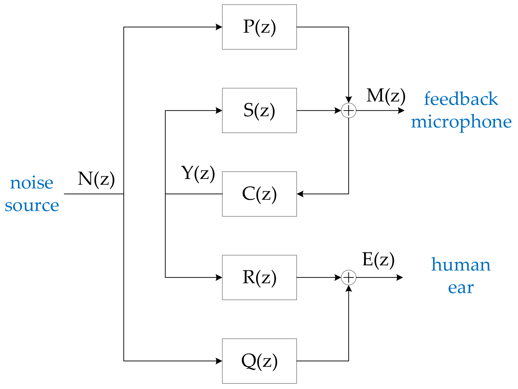
In a feedback ANC headphone, the feedback loop is generally constructed with the feedback microphone, the controller as well as the speaker. The feedback microphone is used as the error sensor to pick up the residual noise signal inside the earcup, whose output is fed into the controller and then drive the speaker to generate a secondary noise so that the primary noise could be reduced. The schematic diagram of a typical feedback ANC headphone is shown in
Figure 1, where C(z), S(z) represent the transfer functions of the controller and the secondary path, M(z) and Y(z) denote for the z-transforms of the outputs of the feedback microphone and the controller, respectively. The primary noise P(z)N(z) is modeled by an outside noise signal N(z) transmitting through the primary path P(z). With the abovementioned definitions, the closed-loop sensitivity function of the feedback control system can be written as:
whose magnitude response represents the NR performance at the feedback microphone. In order for a better NR performance, the FR of the controller C(z) should be enlarged as much as possible within the frequency band where active control of noise is expected to be effective, and should be attenuated as the frequency gets higher so that the noise enhancement could be limited according to the waterbed effect. Various optimization and control methods have been proposed with different kinds of controllers [
2,
3,
4,
5,
6,
7,
8,
9,
10,
11,
12,
13,
14] and generally a good NR performance could be expected at the feedback microphone position.
However, the actual NR performance would be perceived by the human ear, whose position is different from the one of the feedback microphone. In
Figure 1, the residual noise signal perceived by the human ear is denoted by E(z), which can be written as:
where Q(z), R(z) represent the primary and secondary paths for the human ear, respectively. Another sensitivity function can be defined at the human ear position as the ratio between the residual noise E(z) and the primary noise Q(z)N(z)
where
Similarly, the magnitude response of (3) represents the actual NR performance at the human ear position.
In (4), T(z) is the complementary sensitivity function corresponding to the feedback microphone, which could be seen as a normalized secondary noise (normalized with the primary noise). When T(z) = −1, the secondary noise has the same amplitude but the opposite phase so that the primary noise could be totally eliminated at the feedback microphone position. However, as shown by (3), at the human ear position this normalized secondary noise is disturbed by Δ(z), which represents the FR mismatches between the feedback microphone and the human ear. It can be observed from (4) that FR differences of both the primary and the secondary paths contribute to the FR mismatch term Δ(z). If no FR mismatches exist (i.e., Δ(z) = 1), we have Gmic(z) = Gear(z), which indicates the same NR performances would be obtained at both the feedback microphone and the human ear.
Within the frequency band where the NR performance is high for the feedback microphone, C(z)S(z) has a large response compared to 1, and thus we have:
It is shown by (5) that the FR mismatch term plays an important role on the actual NR performance perceived by the human ear. As Gmic(z) is rather small in this situation, 1 − Δ(z) would be dominant if relatively large FR mismatches exist, which would make the ANC system lose its effectiveness. This indicates that the acoustic responses of the headphone should be designed carefully so that the FR mismatches are kept as low as possible within the frequency band where the ANC system is effective. Fortunately, this requirement can generally be satisfied at low frequencies since the distance between the feedback microphone and the human ear is small compared with the wave length.
Within the frequency band where the primary noise is enhanced, the complementary sensitivity function T(z) is disturbed by Δ(z), as shown by (3). This indicates that with an obvious FR mismatch, the noise enhancement might still be large for the human ear, although the feedback controller is well-designed and the waterbed effect is limited for the feedback microphone. Unlike the previous situation at low frequencies, the FR mismatches corresponding to both the primary and the secondary paths seem to be inevitable in practice since the frequency gets higher here. To deal with this problem, a common method is to depress the controller response C(z) within the frequency band where large FR mismatches could exhibit [
14]. Consequently, the frequency range for noise enhancement is reduced with this design principle, which generally indicates a reduced NR performance at low frequencies according to the waterbed effect if the noise enhancement level is limited to a fixed value.
3. Optimization Methods for Feedback Controllers
How to optimize the controller is one of the key issues for the design of feedback ANC headphones. The basic principle of feedback controller optimization is to enhance the NR performance at low frequencies as much as possible with the restrictions that the feedback loop should have enough stability margins and that the noise enhancement at high frequencies should be limited.
In this study, cascade biquad filters [
14,
20] are used as feedback controllers, which is in accordance with most commercial applications of feedback ANC headphones. Specifically, two prototypes of parametric biquad filters with minimum phase frequency responses are used, whose effectiveness has been confirmed in a previous work [
20]. The transfer functions are listed as follows:
where
and f
s is the sampling frequency. It could be seen that both (6) and (7) are depending on a parameter set g, f and Q. H
0(z) in (6) is a peak/notch filter since the FR is enhanced by g dB at frequency f. The FR of H
1(z) is enhanced by g dB within low frequency band and f can be seen as the cutoff frequency. Hence, H
1(z) in (7) is called the low/high shelf filter. For both H
0(z) and H
1(z), Q plays the role of the quality factor. Some typical FRs of H
0(z) and H
1(z) with different combinations of g, f and Q can be found in [
20].
The feedback controller is constructed with N biquad filters. Since the controller has a cascade structure, its FR should be the product of all individual FRs of each biquad filter. Thus, the FR of the feedback controller is depending on the following parameter vector:
where g
i, f
i, Q
i correspond to the i-th biquad filter and Gain is an extra gain of the controller with dB as its unit. The dimension of
X is 3N + 1.
In order to find the optimal feedback controller according to the basic principle described above, an objective function is proposed in this work as follows:
where f
k(k = 1,…,K) are discrete frequencies over the whole frequency band and u(x) is the unit step function.
In the first term on the right-hand side of (10), [f
start, f
stop] is the target frequency band where the primary noise should be attenuated with the designed controller, and G(f
k) is the value of the sensitivity function at f
kAs the magnitude of sensitivity function represents the NR performance, the first term on the right-hand side of (10) gives a weighted total NR performance with wk as the weight coefficients for frequency fk. In order for a better NR performance, this term should be minimized.
The secondary term on the right-hand side of (10) is a punishment term corresponding to the stability margins, where L(X), γ(X) are the magnitude and phase margins with the designed controller, which is determined by X, and Lmin, γmin are their corresponding lower bounds. If the designed controller does not have enough stability margins, this term would address a positive punishment on the objective function and the punishment intensity is ξ1.
The third term on the right-hand side of (10) represents the constraint for noise enhancement at frequencies higher than fstop. If the noise enhancement at fk (>fstop) is larger than a predefined upper bound δk, this term would address a positive punishment value ξ2 on the objective function.
Similar to the case for feedforward controller design [
20], an upper bound
ub as well as a lower bound
lb are imposed on the parametric vector
X, so that the parametric space could be reduced and the optimization process could be eased. The fourth term on the right-hand side of (10) gives the punishment if
X exceeds its predefined bounds, where sum(·) denotes for the summation over a vector and ξ
3 is the punishment intensity.
It can be found that in order to minimize the objective function defined by (10), all the punishment terms should be forced to 0 if proper intensity values are chosen. This indicates that the feedback control system has enough stability margin and the noise enhancement is also limited for all frequencies. Thus, two optimization methods are proposed, as follows:
For Method 1, the NR performance and noise enhancement are evaluated at the feedback microphone, which is in accordance with previous works. However, if the headphone presents large FR mismatches, the actual performance perceived by the human ear would deteriorate, as analyzed in
Section 2. Instead, the evaluation point is set to the human ear in Method 2 and a better actual performance of the feedback ANC headphone could be expected. It should be noted that in Method 2 the FR corresponding to Δ(z) should be tested and known as a priori.
In this work, DE algorithm is used to solve the optimization problems shown by (13) and (14). DE algorithm is considered to be powerful and efficient to find the global minimum with respect to optimization problems with large scale parametric spaces [
19]. Unlike the genetic algorithm, which needs to discretize the space of variables, the DE algorithm operates directly over the continuous space, which is more straightforward to find the global minimum and the combination with other optimizers [
14] could be avoided. Another advantage of DE is that its implementation is rather simple and straightforward. The number of control parameters in classical DE is very few, which are the crossover rate Cr, the stepsize F, and the population members NP, respectively. With a set of appropriate values of the control parameters, DE would search for the global minimum iteratively and stop when the iteration number reaches its maximum value. It is suggested that the optimization process with DE algorithm should be repeated for multiple times to avoid local minimum points.
4. Experiment Results
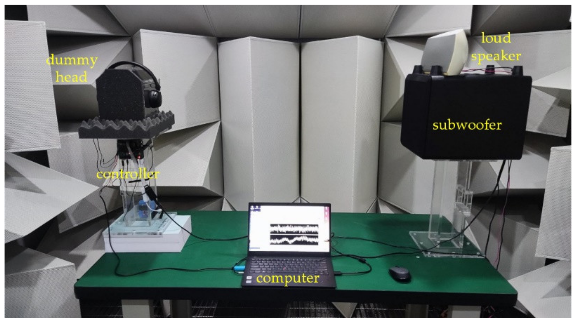
In this section, experiments are carried out with a commercial ANC headphone to verify the proposed methods. The experimental system is shown in
Figure 2. A self-designed acrylic box is used as the dummy head and the microphone fixed on its right-hand side is used as the dummy head ear. The primary noise is generated by the combination of a loudspeaker as well as a subwoofer. The subwoofer is used as a complement of the loudspeaker to generate noise below 100 Hz. The distance between the dummy head ear and the primary noise sources is about 1 m. A self-designed controller with ADAU1772 as its core is used to implement the feedback control. The internal sampling frequency of ADAU1772 is 192 kHz. The controller can also upload signals sampled by ADAU1772 to the computer, with which acoustic FRs of the experimental system can be tested.
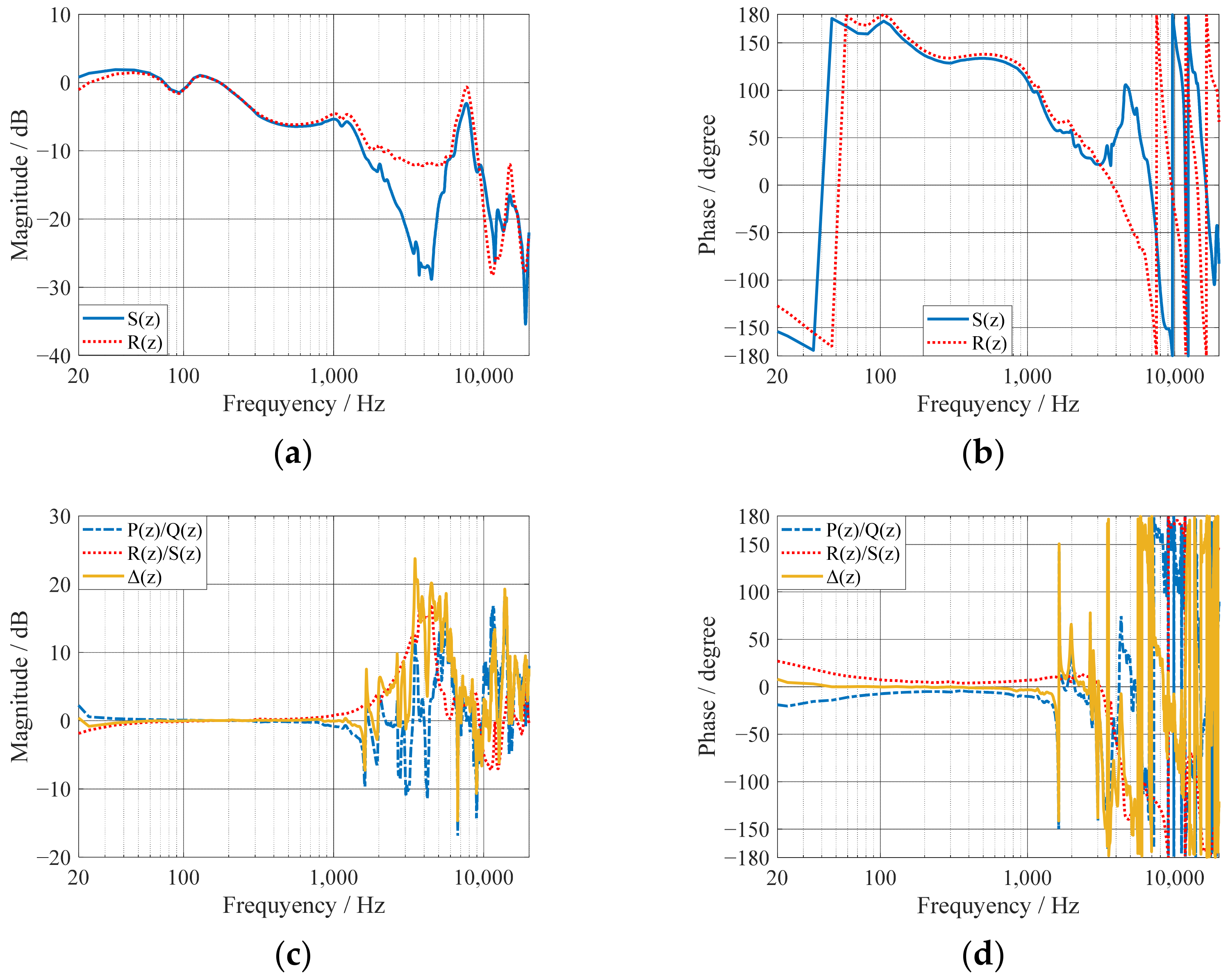
First, both S(z) and R(z) are tested with a white noise stimulus to the headphone’s speaker.
Figure 3a,b show the tested magnitude and phase responses, respectively. It could be seen that the FRs of the secondary paths are in high accordance with each other below 1 kHz, but show large differences in the range from 2 to 6 kHz. This is confirmed by the FR mismatch term R(z)/S(z) for the secondary path, whose responses are shown in
Figure 3c,d. Then, a white noise is played by the primary noise sources and the FR of P(z)/Q(z) is tested with sampled signals of both the feedback microphone and the dummy head ear. The results are also shown in
Figure 3c,d, from which it could be found that the primary paths also exhibit larger differences above 1 kHz. Finally, the responses of Δ(z) are calculated, as shown by the yellow lines in
Figure 3c,d. It can be observed that FR differences of both the primary and secondary paths contribute to the FR mismatch term Δ(z). In the frequency range below 1 kHz, Δ(z) approximately equals to 1, which indicates that the NR performances at the feedback microphone and the dummy head ear would be in high accordance. However, Δ(z) could exhibit large values when the frequency gets higher. Consequently, large noise enhancement might arise at the dummy head ear even if it is limited to a low value at the feedback microphone, just as analyzed in
Section 2.
With the tested acoustic FRs, the cascade biquad filters of the feedback controller could be designed with the proposed methods. In the objective function described by (10), the frequencies f
k are discretized logarithmically from 20 to 20 kHz and K is set to 300. According to the frequency range where the FR mismatch is small, the target frequency band [f
start, f
stop] is set to [20 Hz, 1 kHz]. The weight coefficients w
k are set to 1 for [50 Hz, 500 Hz], within which the NR performance is expected to be strengthened, and set to 0.2 for 20 Hz as well as 1 kHz. All the other w
k are obtained by linear interpolation. In the design process, the minimum magnitude margin L
min and the minimum phase margin γ
min are set to 10 dB and 30°, respectively. A constant noise enhancement limitation is chosen, i.e., δ
k = δ for all f
k > f
stop. All the punishment intensity parameters ξ
1, ξ
2, ξ
3 are set to 10,000. In the feedback controller,
N = 5 biquad filters are used. The filter prototypes and the corresponding bounds of the parametric vector
X is shown in
Table 1. It can be seen that by setting different values of g within
lb and
ub, the biquad filters could be forced into different types even if the same prototype is used.
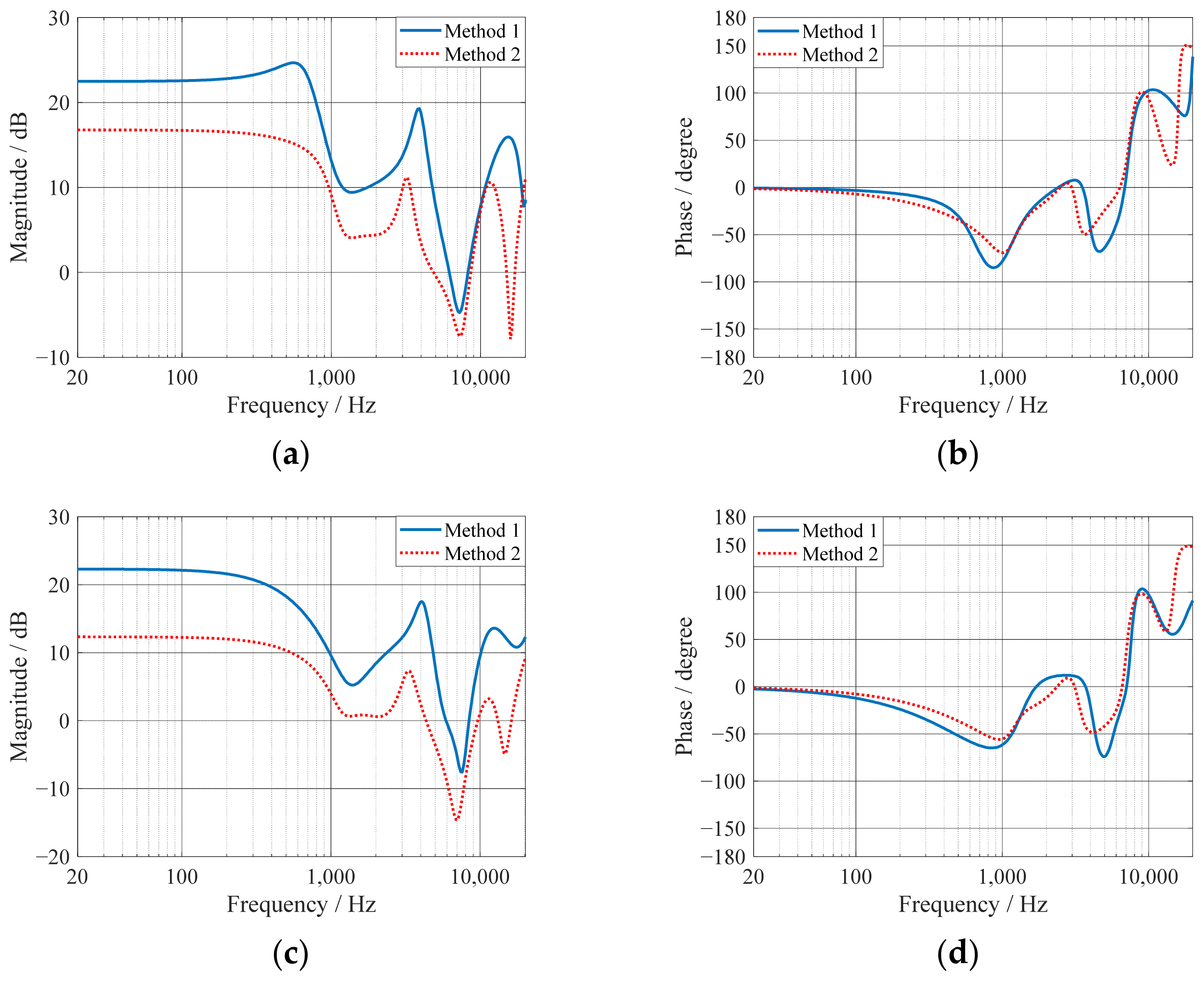
With the parameters described above, the feedback controller is designed with both Method 1 and Method 2. For each method, the controller is designed respectively with two different noise enhancement limitations δ = 5 dB and δ = 3 dB. DE algorithm is used to solve the optimization problems defined in (13) and (14), where the crossover rate Cr, the stepsize F and the popular members NP are set to 1, 0.85 and 100, respectively. The iteration number is set to 10,000. For each case the optimization process with DE algorithm is repeated for 100 times in order for the global minimum. The design results with different δ and different methods are shown in
Table 1. The corresponding FRs of the controllers are shown in
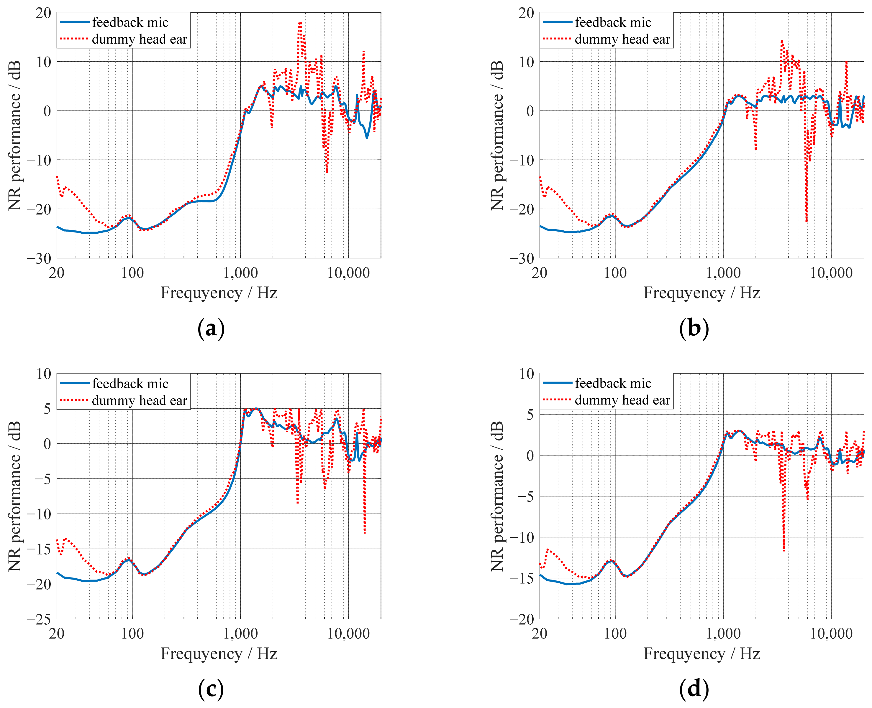
Figure 4. With these results, the expected NR performances could be calculated and are shown in
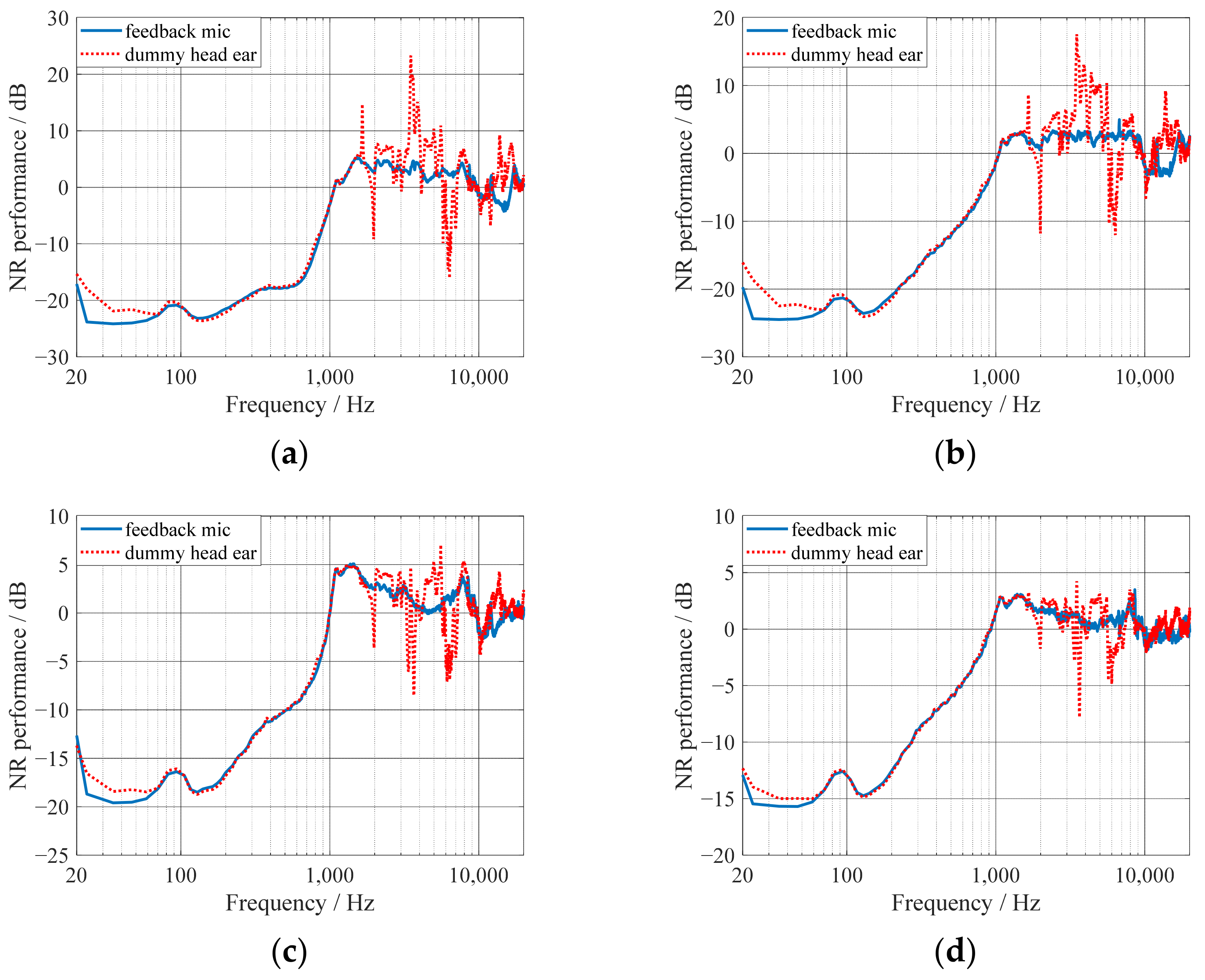
Figure 5. Finally, the filter coefficients are download into ADAU1772 through SigmaStudio and the actual NR performances are tested by experiments, which is shown in
Figure 6. All the NR performances shown in
Figure 5 and
Figure 6 are represented by the magnitude responses of the corresponding sensitivity functions defined in (1) and (3).
When the feedback controller is designed with Method 1, the performance is only evaluated at the feedback microphone position just as previous works. It could be observed from
Figure 5a,b that the noise enhancements are nearly flat at high frequencies without exceeding its limitations, which generally indicates that almost the optimal NR performances could be expected. Meanwhile, a better NR performance could be obtained with a loose limitation on the noise enhancement. At the dummy head ear position, the NR performances below 1 kHz are in accordance with the ones at the feedback microphone position, which is a natural result since the FRs of the primary and secondary paths are almost the same. However, large noise enhancements appear within the frequency band [2 kHz, 6 kHz], which result from large FR mismatches shown in
Figure 3. This indicates that the FR mismatches of both the primary path and the secondary path should be addressed in the controller design stage.
With Method 2, such large noise enhancements could be avoided, as shown in
Figure 5c,d, since the FR mismatches are considered and the NR performance at the dummy ear position is directly under evaluation. This results from the reduced magnitude and the shifted phase of the controller at frequencies where the FR mismatch is relatively large, as shown in
Figure 3. Although the NR performances below 1 kHz are reduced compared with the ones of Method 1, which are also indicated by the reduced magnitude responses of the controllers, the designed results of Method 2 could still be seen as the ones with almost the best comprehensive performances. A reduced NR performance seems to be a necessary compromise for the limitation of noise enhancement at the dummy head ear if large FR mismatches exist. The above results have been confirmed by experiments, which are in high accordance with the simulations, as shown in
Figure 6.


