Article

Numerical Study on the Applicability of the Pipe-Jacking Method for the Main Gate of an Underground Coal Mining in Weak Rock Mass

Department of Earth Resources Engineering, Faculty of Engineering, Kyushu University, Fukuoka City 819-0395, Japan
*
Author to whom correspondence should be addressed.
Appl. Sci. 2022, 12(3), 1719; https://doi.org/10.3390/app12031719
Submission received: 12 January 2022 / Revised: 1 February 2022 / Accepted: 1 February 2022 / Published: 7 February 2022

Abstract

:
The typical reinforcements and supports used in the main gate of underground coal mining (particularly in the weak to very weak rock strata), such as rock/cable bolts, steel sets, and grouting materials, often allow the mine to remain serviceable in the long run, but in complicated geotechnical and geological conditions, they are insufficient. Low rock strength leads to instability and exhibits serious ground control issues. The pipe-jacking method with a precast concrete pipe support can be one of the more appropriate options for significantly improving geotechnical concerns. This paper aims to study the applicability of pipe-jacking technology in underground coal mining based on a series of numerical analyses employing a three-dimensional FEM (3D-σ software, Geoscience Research Laboratory Co Ltd, Kanagawa, Japan). In the numerical analyses, we study the crown deformation and failure proximity using different inclination angles for the tunnel, different highwall slopes, and two different shapes for the pipe. It is important to note that a precast concrete pipe is effective as a primary support system and can improve the stability of the main gate efficiently.

1. Introduction

The increasing demand for coal due to global economic growth and the depletion of coal resources from favorable geological sites force engineers to re-evaluate the safety of underground mining and to create more effective tunneling methods and better supporting procedures. Ground control in weak rock is always an interesting challenge for researchers. Designing good supports for tunnels created in weak rocks is a complex problem [1] due to the low quality of the rock mass and the possibility of large deformations. Therefore, the pipe-jacking method with thick concrete pipe supports is proposed in this paper. Rocks with an estimated uniaxial compressive strength [2] of less than 25 MPa can be classified as weak, very weak, and extremely weak. Weak rocks that have low strength and high expansibility easily result in large deformations and severe fractures in the surrounding rock, which lead to instability.
The rock bolt system has been widely used in UK and Australian underground coal mining practices. However, the deformation and fracture behavior of roadways in weak rocks cannot be controlled by a rock bolting system in cases where the development rate is slow and when the roadway/entry has to be maintained for a long time; consequently, additional support needs to be installed [3]. Due to the difficulty of achieving an adequate anchorage of the rock bolts and cables, steel-set or concrete/shotcrete-lining support systems are more appropriate [1]. Moreover, to prevent large deformations in the surrounding rocks due to the dynamic disturbances caused by mining, a support consisting of constant resistance, large deformation bolts, steel strips, and grouting bolt pipes was suggested by [4]. In addition, in the Xingdong mine, a support system based on the bearing strength theory combined a super-imposed arch using an ‘’anchor spray net+anchor cable” to support the deep, weak surrounding rock [5] and the “elliptical concrete-filled steel tube supports + deep + shallow cross grouting reinforcement” composite scheme to reduce the number of deformations in the surrounding rock, which has worked effectively [6].
Moreover, the application of rigid steel-arc support as a primary support system in a weak surrounding rock roadway was suggested, and a comparison of actual field measurements and numerical results has been made [7]. Additionally, “a high-strength concrete-filled steel tube” support structure has shown significant improvement when used to control the deformation around the roadways in the Chaganmuer mine and, thus, to effectively control the deformation and to ensure its safety [8]. Recently, many Chinese researchers have suggested using a concrete-filled steel tube support combined with auxiliary supports for deep, soft rock tunnels that are under high in situ stress.
The main gate of a mine is excavated horizontally (or gently) for purposes such as coal haulage, material transportation, worker access, and ventilation from the ground to the coal deposits; thus, its stability is imperative. In this paper, we study the stability of the main gate based on numerical analysis with a three-dimensional finite element method (3D-σ software).
To determine the level of crown deformation in the rocks from the roof of the tunnel and the failure proximity of a concrete pipe, the mechanical properties of the rocks in a coal mine in Indonesia were used in this analysis. An increasing number of new mines are being planned and a number of existing mines are being extended, with life spans of over 40 years. For such projects, it may be prudent to consider adopting design standards that are commensurate with civil engineering tunnels [9].

2. Engineering Background

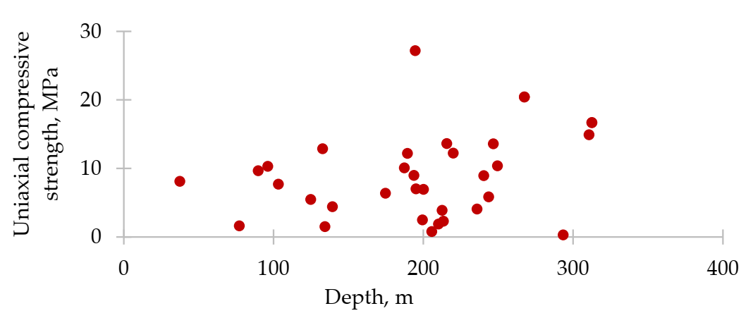
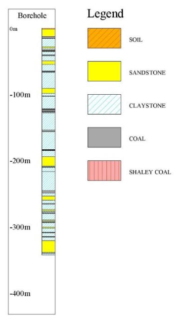
2.1. Geology and Rock Quality

The Kutai basin received lateral pressure from the eastern side in the late Miocene; therefore, this basin has a large syncline structure from the northeast to southwest, with the large syncline structure including many folds. The Balikpapan coal-bearing formation is a major part of the Kutai basin, and many coal seams are found by drilling holes at this site. This formation mainly consists of claystone, mudstone, sandstone, siltstone, coal, and coaly shale. The coal seam dips at around 15 degrees and is quite gentle in the west. The direction of this dip is from the north to south and changes to the northeast to southwest near the southern concession. This change was confirmed by an outcrop survey and by drilling. This research field has a simple monocline structure, and a large fault zone was not found.
In general, the rock mass quality of sedimentary deposits in Indonesia is quite poor, being composed of sediment rocks that are typically found in deltaic and shallow marine depositional environments. The rocks are typically weak and very weak, especially at shallow depths, and are strongly deteriorated by the waters from heavy rain and tropical climate conditions. Even at relatively shallow mining depths, the rock has extremely little strength, high weathering, and poor cementation and claystone is dominant in this Indonesian coal mine in Figure 1.
When considering the worst-case scenario, the mechanical properties of claystone are used as the input parameters in our numerical analysis, where claystone is classified as a weak and very weak rock according to practical estimates of the rock mass strength. Some of the claystone’s properties are similar to that of the soil, especially near the ground surface, easily deforming, with large surface subsidence occurring due to underground excavations. In shallow mining practices, the mechanical behavior of the rock mass is usually brittle. Also, the size of plastic deformation is often small. However, in this case, it is observed that a large crown deformation occurs close to the tunnel’s entrance due to the rocks being weak.
In order to determine the relationship between the mining depth and the uniaxial compressive strength, measurements were taken using the point load test method and the SH-70 field estimation technique on borehole cores. In addition, an extensometer and tell-tale techniques were installed into the roof and sidewall rock at 90° and 45°, respectively.
Two parallel and gently inclined roadways were excavated from the final highwall and supported by a steel arch with the spacing of 1.1m; the inclination angle varied from 5° to 15°, and in order to preserve the long-term serviceability of the main gates, a combination of steel-arch, thick-concrete, and rock-bolt supports were applied as well; this has been effective thus far. The evaluation of the rock mass strength is an essential part of a geotechnical investigation. The uniaxial compressive strength that is estimated by the point load test can represent the initial rock strength’s characteristics, the correlation of the uniaxial compressive strength test results of claystone, and the mining depth (shown in Figure 2, which is based on the borehole data, and in Figure 3, where the stratigraphy column is presented).

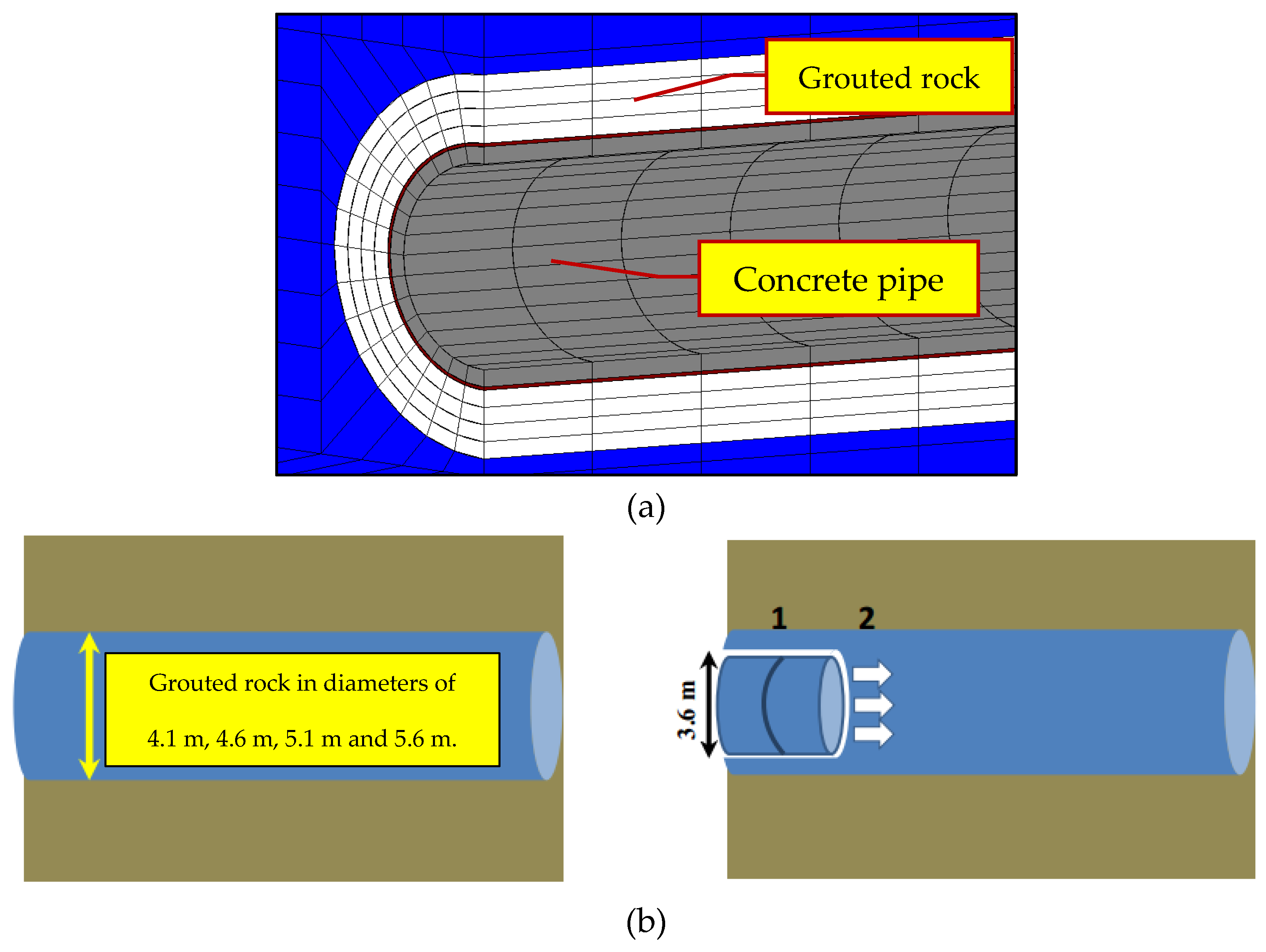
2.2. Model Establishment

In order to determine the failure proximity of the concrete lining, and the crown deformation characteristics occurring in the rocks from the roof of the tunnel caused by extending the tunnel using the pipe-jacking method, a series of numerical simulations were carried out with a 3D-σ software that can calculate the stress conditions, displacement, failure, and various possible predictions of the rocks in this engineering problem.
The failure proximity and crown deformation are considered in order to determine the possible length of the tunnel and the endurance of the concrete pipe. The failure proximity coefficient can reach up to one, which shows the possibility of damage and breakage in a concrete pipe. On the other hand, the full length of the tunnel can be determined using a failure proximity coefficient of one, in which the pipe-jacking process cannot continue further. After the boundary conditions, failure criterion, and model design were considered, the model was established, producing conditions similar to actual field conditions as illustrated in Figure 4. In addition, to reduce the number of errors and to control the effects of each variable, the model boundaries were pre-set until their effect was minimal or non-existent.
Moreover, the three different tunnel inclination angles, the three highwall slopes, and the two types of tunnel shapes were assumed to be 5°, 10°, and 15°; 7.5°, 15°, and 30°; and circular and rectangular, respectively. In addition, the model’s boundaries were constrained in all directions, except for the top boundary, which was free, and gravity was set as an initial stress condition. In the civil engineering of soft rock tunnels, some types of lubricant or grouting materials can be used and injected into over-cutting areas to decrease the frictional resistance of the concrete pipe and the tunnel surface during the thrusting process. It can also reduce the jacking force and energy consumption and can increase the jacking efficiency.
The mechanical properties of claystone and other materials in Table 1 and Table 2 that were used in the numerical simulation were obtained from the mining company with permission. The uniaxial compressive strength measured using the point load test on the borehole cores was obtain by some of the authors during field investigations at the coal mine.
In this paper, we aim to study the effect of tunnel inclination, highwall slope, and pipe shape rather than the material properties and complex geology. Therefore, our model is homogenous, and the different rock layers and mechanical properties were not considered in this study.

3. Results of Numerical Analysis and Discussion

In order to evaluate the stability of the roadways, (a) the failure proximity and (b) the crown deformation, which represents the ground behavior, displacement, and fracturing, were considered under some specific conditions.

3.1. Field Measurement

According to the measurement data collected from the tell-tale technique and extensometer used during the two months of field investigations of the roadway from the underground coal mine project, the roof displacement drastically increased upwards of 9.5 mm within less than 0.6 m of drilling into the rock as shown Figure 5. Although numerous displacement measurements have been taken during the extension of the main roadway which had been done from December 2015 to February 2016, the measurement results by extensometer-01, which was installed at around a depth of 13 m and a distance of 60 m from the entrance of the main gate, was selected to compare the actual field deformation and the numerical analysis results.
The mining depth assumed at the end of the tunnel is around 10 m, which is a relatively shallow depth. Despite the difference in the geological conditions, a correlation between the results of the numerical analysis and field data can be seen as reasonable and can be explained logically.

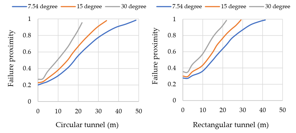
3.2. Failure of Concrete Lining Support

The failure proximity [10,11] is an evaluation index based on the failure criterion defined by Mohr and Coulomb, which is used to evaluate the safety of the materials or structures used under specific working conditions. The Mohr–Coulomb criterion is applied in a numerical simulation to determine the failure probability and the length of the tunnel at which the failure proximity reaches one.
In civil engineering, it is normally assumed that the failure proximity is a significant factor to consider when proceding with the jacking process. Therefore, the results of the numerical analysis represent the possible length for excavation of a tunnel using pipe-jacking technology supported by a concrete-lining support at different inclination angles, highwall slopes, and tunnel shapes. Figure 6 and Figure 7 show the effects of and relationships between the aforementioned conditions.
It is shown that a small angle of inclination for the tunnel allows for greater advances using the pipe-jacking technology. According to Figure 6, the lengths of circular and rectangular tunnels are approximately 48.6 m and 41.3 m, respectively, when the tunnel is inclined by 5°, which is nearly horizontal. When increasing the inclination angle to 15°, the tunnel length decreases by 16.9 m for the circular tunnel and by 12.2 m for the rectangular tunnel.
Different tunnel inclinations and highwall slopes increase the in-situ stress and overburden the depth when extending the tunnel, significantly limiting the tunnel length that can be excavated by pipe-jacking. The numerical results for the changes in the highwall slopes are also similar. Figure 7 shows that the lengths of the circular and rectangular tunnels are approximately 48.1 m and 41.1 m, respectively, for a highwall slope of 7.5°. However, when the highwall slope angle reaches 30°, the length of the tunnel that can be supported by concrete lining is decreased by 26.8 m and 19.5 m for the circular tunnel and the rectangular tunnel, respectively.
In Figure 6 and Figure 7, it is clearly shown that a smaller inclination angle of highwall slope allows for a farther pipe-jacking distance. For instance, in the case of a circular tunnel, when the highwall slope angle increases up to 30°, the tunnel length significantly decreases by around 55%, but when the tunnel inclination angle reaches 15°, the tunnel length decreases by 35%. It is important to note that a small inclination angle and a gentle highwall slope can produce a longer and safer tunnel when supported by concrete lining.

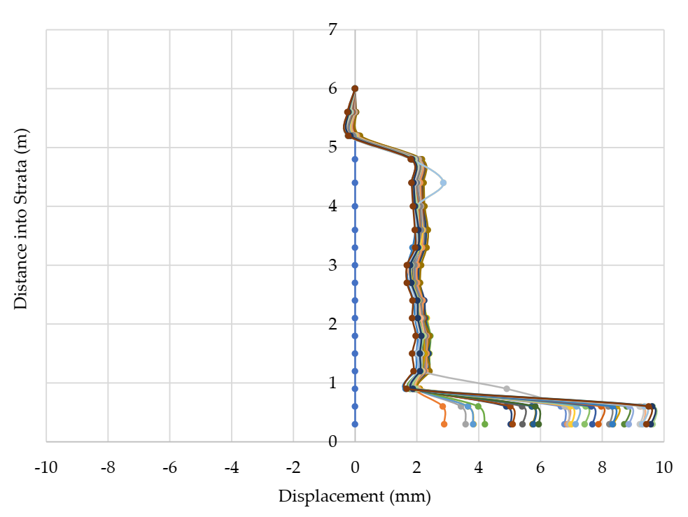
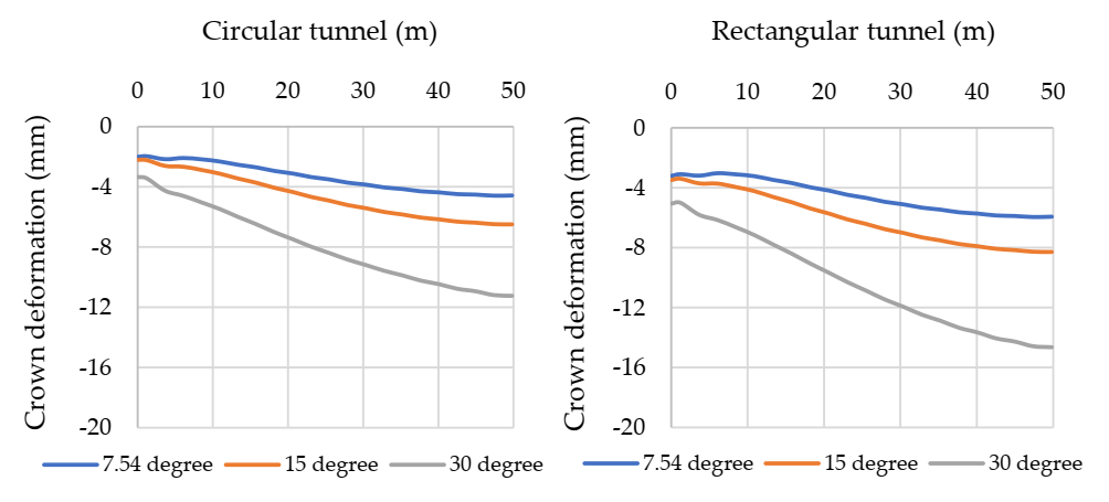
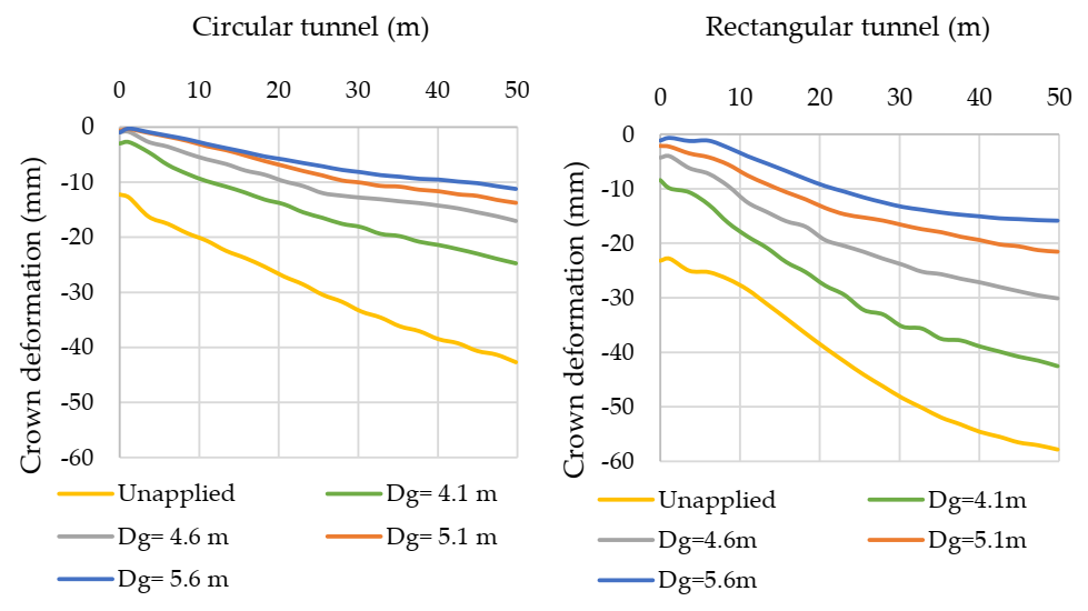
3.3. Crown Deformation

In terms of the pipe-jacking method, crown deformation is an essential engineering criterion that can determine the maximum tunnel length while still ensuring stability. According to recommendations by the Japan Tunneling Association (1997), it is dangerous to proceed with a pipe-jacking process when the overcutting area between the concrete pipe and the roof’s rock surface is less than 30 mm; therefore, additional measures need to be considered to improve the rock strength around a geologically weak/very weak tunnel. For example, various grouting materials are able to be injected into the surrounding rocks of a roadway at various diameters.
Before discussing the application of grouting materials to improve the strength of the surrounding rocks, the effects of the tunnel inclination angles and highwall slopes have to be discussed, shown in Figure 8 and Figure 9. The initial conditions considered here are the same as that discussed in the previous section. However, we also consider another different condition which is grouting method for improving surrounding rock to assess crown deformation.
In practice, the allowable crown deformation typically needs to be less than 20 mm, which is an important factor to consider when ensuring proper working conditions for pipe-jacking technology. Therefore, such practices of tunneling through weak rock or soil require the use of grouting methods to improve the rock quality around the tunnel. As mentioned previously, weak rocks can easily expand, which results in immediate squeezing and a significantly increased resistance force.
It is seen in Figure 8 that, in both the circular and rectangular tunnels, the highest roof displacement occurs with larger inclination angles, which is similar to the previous numerical results. The highest displacements for circular and rectangular tunnels are 8.1 mm and 10.5 mm, respectively (when tunnel inclinations reached up to 15°). The differences in roof displacements are 3.7 mm for the circular tunnel and 4.7 mm for the rectangular tunnel, with inclinations varying from 15° to 5°.
Based on the relationship between the tunnel length and crown deformation/roof displacement presented in Figure 9, roof displacement increased from 4.5 mm to 11.2 mm in the circular tunnel and from 5.9 mm to 14.6 mm in the rectangular tunnel, with the highwall slope becoming steeper. Moreover, the amount of deformation in the figures shows that a circular tunnel is significantly more stable than a rectangular tunnel. However, due to the specific purposes of mining, such as coal haulage, ventilation, material transportation, and worker access, a larger cross-sectional roadway needs to be excavated. It can be summarized that pipe-jacking technology is able to be applied without using a grouting method when the crown deformation being not large (less than 20 mm, as obtained from the numerical analysis).
The grouting material was injected into the surrounding rock at four external diameters—4.1 m, 4.6 m, 5.1 m, and 5.6 m—before the tunnel could be extended, as illustrated in Figure 10; the material properties are listed in Table 3.
Hence, to clarify how much improvement was achieved when using the grouting material, we studied the changes in crown deformation using Young’s modulus, which decreased by some amount and assumed the worst-case scenario. The tunnel inclination was 5° for both shapes, and a comparison of the numerical results is presented in Figure 11.
It is noted that Young’s modulus is reduced by ten times and that the crown deformation drastically increased from 4.3 mm to 42.6 mm in the circular tunnel. Additionally, it increased immensely from 5.8 mm to 57.8 mm in the rectangular tunnel. Regarding the acceptable overcutting area and crown deformation in the practice of civil engineering, the case of E/10 cannot be implemented in actual scenarios.
The E/10 case is considered the worst-case scenario in our further numerical analyses, as presented in the following figures. By grouting the surrounding rock of the tunnel at several diameters, the displacement is significantly decreased, as shown in Figure 12. The initial crown deformation of un-grouted rock is around 42.6 mm in the circular tunnel and 57.8 mm in the rectangular tunnel.
After the grouting material was injected and the rock’s strength improved, the amount of displacement was decreased to 24.7 mm, 17.05 mm, 13.7 mm, and 11.2 mm for each diameter of the circular tunnel and to 42.5 mm, 30.09 mm, 21.5 mm, and 15.8 mm for the diameters of the rectangular tunnel. It is seen that, as the displacement is reduced from 42 to 74% in the circular tunnels and from 26.5 to 73% in the rectangular tunnels, the grouting method is highly efficient, and the selected material significantly improves the surrounding rock masses’ characteristics.
Figure 13 and Figure 14 clearly show the variance in the deformation contours and the reduction in the number of large deformations for both cases in which the grouting material was injected into a 5.6 m diameter tunnel and without grouting.
The largest deformation occurred near the entrance of the main gate and in the surrounding rock from the roof at the end of the tunnel, with the tunnel inclination angle and highwall slope set as 5° and 7°, respectively. According to the numerous numerical results obtained and based on the acceptable crown deformation and over-cutting area, the pipe-jacking method with a pre-cast concrete lining support can be applied at an actual site with weak geological structures, particularly in the weak/very weak rock strata. However, assuming the worst-case scenario, Young’s modulus is reduced by ten times; the grouting method can be considered, and the surrounding rock mass can sufficiently be improved by alternative solutions.
Beyond that, another achievement of this study is the low-cost, due to the optimization of the external diameter of the grouted rock. In Figure 12, the external diameters from 4.1 m to 4.6 m for the circular tunnel and from 5.1 m to 5.6 m for the rectangular tunnel are reasonable.

4. Conclusions

Specific ground behaviors, such as low rock strength, high geological stress, large deformations, and high expansibility, can result in unsuitable circumstances that typical support systems (for example, rock/cable bolts and steel sets) cannot sufficiently maintain, causing safety issues.
Moreover, to address the increasing demand for coal in energy production and the worsening of geological and geotechnical conditions, the application of pipe-jacking technology (one of the alternatives for efficient civil engineering in the main gate of underground coal mining in the weak rock strata) was studied under several conditions using a series of numerical analysis and the finite element method.
According to the results of the numerical analysis, the following can be concluded:
(1)
We recommend using pipe-jacking technology, combined with or without the grouting method, as a reasonable and safe method that allows the main gate of an underground coal mine with weak geological structures to remain serviceable in the long run.
(2)
Although the tunnel length is limited by high failure proximity and large crown deformation, concrete-pipe supports can be installed as a primary support system to control the ground problems without the use of auxiliary supports.
(3)
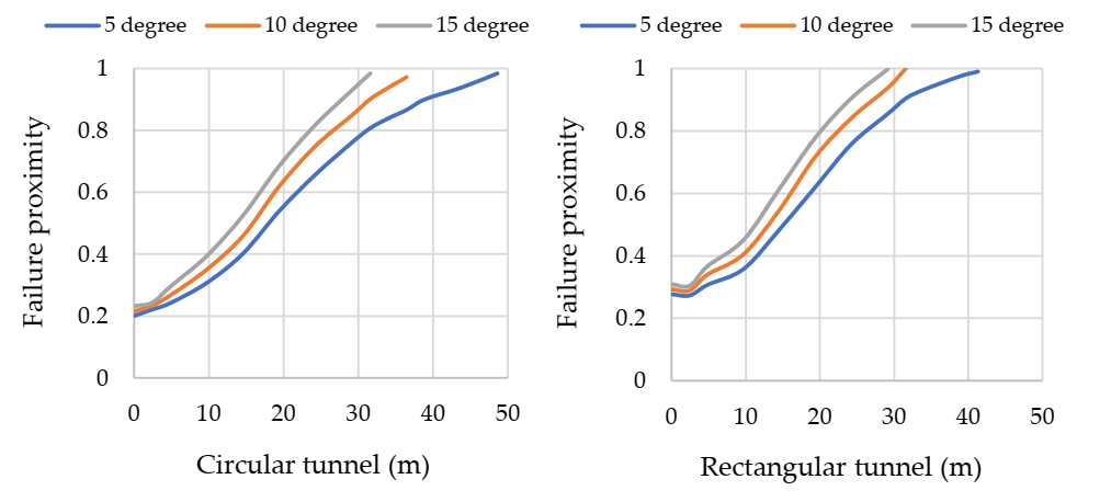
Based on the failure proximity coefficient, the tunnel length can reach up to 50 m, obtained with a critical coefficient of one. This shows that, if the tunnel length exceeds 50 m, some serious damage will occur in the concrete-lining support.
(4)
High tunnel inclination angles and highwall slopes result in an increasing, overburdened depth and high geological stress, which are the main factors causing significant crown deformation.
(5)
A tunnel that is circular is much more stable than one that is rectangular. However, selecting which shape to use and what cross-sectional area is optimal depend a lot on the goal of the mining project.
(6)
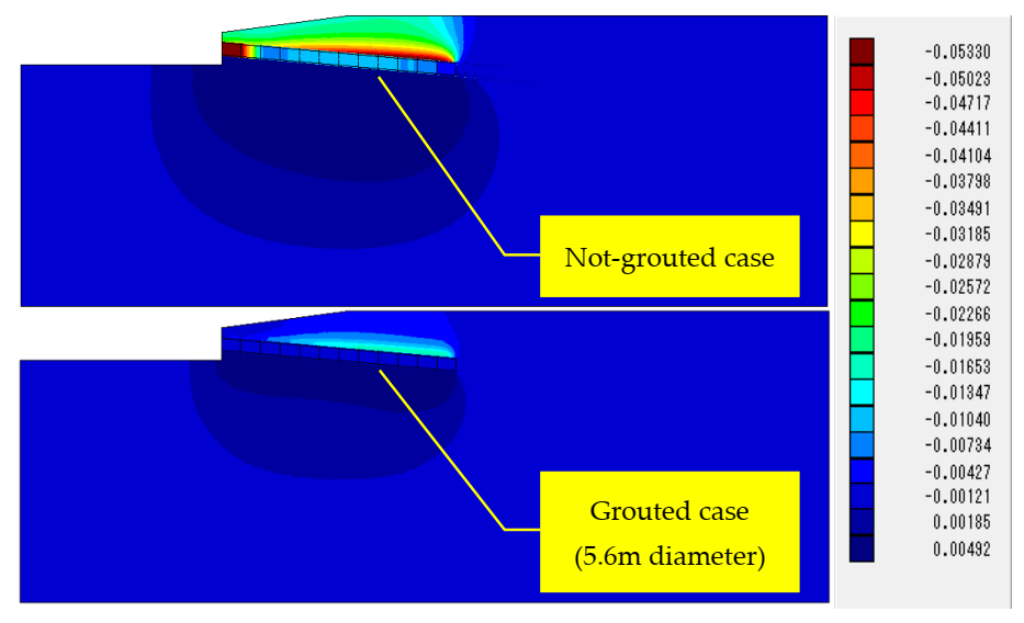
According to the worst-case scenario in which Young’s modulus is reduced, it is clearly shown that improvements to the surrounding rock have to be considered. In addition, it suggests that the grouting method can be a highly efficient approach used to solve these types of problems in an actual scenario and can extend the tunnel’s length in order to be supported by concrete lining.

Author Contributions

Conceptualization, U.B., T.S. and H.S.; methodology, U.B. and H.H.; software, U.B. and H.H.; validation, U.B., T.S. and A.H.; formal analysis, U.B., H.H. and A.H.; investigation, U.B., H.H., T.S. and A.H.; resources, U.B., T.S., H.S. and A.H.; data curation, U.B. and T.S.; writing—original draft preparation, U.B.; writing—review and editing, U.B., T.S., H.S. and A.H.; visualization, U.B.; supervision, T.S., H.S. and A.H.; project administration, U.B. and A.H.; funding acquisition, T.S., H.S. and A.H. All authors have read and agreed to the published version of the manuscript.

Funding

This research received no external funding.

Data Availability Statement

The data used to support the findings of this study are available from the first author upon request.

Acknowledgments

The authors express special gratitude to Naung Naung, a very kind colleague and researcher who gave precious advice. The authors also express sincere thanks to the mining company in Indonesia for permission to conduct the fieldwork, providing information, data, and samples for the current research. Moreover, the authors express great appreciation for the JDS program, Japan International Cooperation Center (JICE).

Conflicts of Interest

The authors declare no conflict of interest.

References

  1. Hoek, E. Tunnel support in weak rock. In Proceedings of the Symposium of Sedimentary Rock Engineering, Taipei, Taiwan, 20–22 November 1998. [Google Scholar]
  2. Hoek, E.; Brown, E.T. Practical estimates of rock mass strength. Int. J. Rock Mech. Min. Sci. 1997, 34, 1165–1186. [Google Scholar] [CrossRef]
  3. Sasaoka, T.; Takamoto, H.; Shimada, H.; Oya, J.; Hamanaka, A.; Matsui, K. Surface subsidence due to the underground mining operation under weak geological condition in Indonesia. J. Rock Mech. Geotech. Eng. 2015, 7, 337–344. [Google Scholar] [CrossRef] [Green Version]
  4. Guo, Z.; Wang, J.; Zhang, Y. Failure mechanism and supporting measures for large deformation of tertiary deep soft rock. Int. J. Min. Sci. Technol. 2015, 25, 121–126. [Google Scholar] [CrossRef]
  5. Qi, G.; Li, Z.-J.; Guo, Z.-B. Coupling support design for deep pit bottom in No. 5 coal mine of He Bi coal industry group and its application. J. Min. Saf. Eng. 2011, 28, 553–559. [Google Scholar]
  6. Wang, J.; Chen, F. Application of concrete-filled steel tube support in repairing the 1000m-deep roadway. Tunnel Constr. 2013, 33, 774–778. [Google Scholar]
  7. Pongpanya, P.; Sasaoka, T.; Shimada, H.; Hamanaka, A.; Wahyudi, S. Numerical study on the effect of longwall mining on the stability of the main roadway under weak geological conditions. J. Geol. Resour. Eng. 2017, 3, 93–104. [Google Scholar]
  8. Li, X.-B.; Yang, R.-S.; Gao, Y.-F.; He, X.-S.; Wang, C. High strength concrete-filled steel tubular support technology for large section soft rock inclined shaft. J. Coal 2013, 38, 1742–1748. [Google Scholar]
  9. Brox, B. Technical considerations for TBM tunneling for mining projects. Trans. Soc. Min. Metall. Exploit. 2013, 334, 498–505. [Google Scholar]
  10. Oke, J.; Vlachopoulos, N. Improvement to the convergence-confinement method: Inclusion of support installation proximity and stiffness. Int. J. Rock Mech. Rock Eng. 2018, 51, 1495–1519. [Google Scholar] [CrossRef]
  11. Peng, M.; Shimada, H.; Sasaoka, T.; Hamanaka, A.; Dintwe, T.K.M.; Pan, D. Investigation on the performance of pipe roof method adjacent to the underground construction. J. Geotech. Geol. Eng. 2021, 39, 4677–4687. [Google Scholar]
Figure 1. View of the main gate of the Indonesian coal mine.
Applsci 12 01719 g001
Figure 2. Correlation between the uniaxial compressive strength of claystone and mining depth.
Applsci 12 01719 g002
Figure 3. Simplified geological stratigraphy column.
Applsci 12 01719 g003
Figure 4. (a) Schematic view of the model: (b) circular pipe and (c) rectangular pipe.
Applsci 12 01719 g004
Figure 5. Roof displacement measured by extensometer 01.
Applsci 12 01719 g005
Figure 6. Relationship between tunnel length and failure proximity with different tunnel inclination angles.
Applsci 12 01719 g006
Figure 7. Relationship between tunnel length and failure proximity under different highwall slopes.
Applsci 12 01719 g007
Figure 8. Effect of tunnel inclination angles on crown deformation.
Applsci 12 01719 g008
Figure 9. Effect of highwall slopes on crown deformation.
Applsci 12 01719 g009
Figure 10. General scheme of the grouting and jacking process: (a) scheme of grouted rock and concrete lining, and (b) grouting and tunneling steps.
Applsci 12 01719 g010
Figure 11. Effect of decreasing Young’s modulus on crown deformation.
Applsci 12 01719 g011
Figure 12. The difference in crown deformation with grouted rock at various diameters (Dg—Total diameter of grouted rock and tunnel).
Applsci 12 01719 g012
Figure 13. Deformation contour of a circular tunnel with and without grouting.
Applsci 12 01719 g013
Figure 14. Deformation contour of a rectangular tunnel with and without grouting.
Applsci 12 01719 g014
Table 1. The mechanical properties of the rocks and lubricant materials.
Input ParametersClaystoneLubricant Material
After Injection1 Month Elapsed
Unit weight (MN/m3)0.02170.0220.022
Young’s modulus, E (MPa)153.09.8 × 10−40.41
Poison’s ratio, v0.260.450.39
Table 2. Mechanical properties of the concrete pipe.
Unit Weight
(MN/m3)
Young’s Modulus
E (MPa)
Poison’s Ratio
v
Shear Strength
(MPa)
Friction
Angle
(o)
Tensile Strength
(MPa)
0.02633,000.00.177.0452.8
Table 3. Grouting material properties.
MaterialYoung’s Modulus
E (MPa)
Poisson’s Ratio
v
Unit Weight
(MN/m3)
Grouting material2000.30.022
Publisher’s Note: MDPI stays neutral with regard to jurisdictional claims in published maps and institutional affiliations.

