Article

Parametric Study of Three Types of Timber Connections with Metal Fasteners Using Eurocode 5

Mechanical Engineering Department, School of Engineering, Polytechnic Institute of Porto, Rua Dr. António Bernardino de Almeida, 431, 4200-072 Porto, Portugal
*
Author to whom correspondence should be addressed.
Appl. Sci. 2022, 12(3), 1701; https://doi.org/10.3390/app12031701
Submission received: 21 December 2021 / Revised: 26 January 2022 / Accepted: 31 January 2022 / Published: 7 February 2022
(This article belongs to the Special Issue Structural Design and Computational Methods)

Abstract

:
This work presents the results of three types of timber connections, in double-shear, with metal dowel-type fasteners, using the simplified equations from of Eurocode 5. All the design parameters were established and compared using three different properties of strength and density of the wood that represent the connecting members. A total of eighty-one connections were obtained, allowing for the determination of the number of fasteners needed for the applied tensile load. A large number and different types of connections allow the verification of the effect of the dowel parameters together with the wood characteristics. In all of the types of timber connections studied, the number of dowels increases with the applied tensile load, with lower dowel diameter, lower wood density, and strength. The design characteristic load-carrying capacity per shear plane and fastener also decreases with the previously considered parameters.

1. Introduction

Timber connections have been studied by researchers from several countries, where different analytical and experimental models are developed to solve many questions about this type of elements.
These elements are considered the essential parts of a wooden structure due to their ability to connect parts, transmit high loads, and, therefore, require more importance during the project [1,2]. However, these connections can also be the weakest points in the structure [3,4]. The connections have the function of transmitting the load-carrying capacity between the parts of the structure and providing continuity between the members. Thus, the strength and durability of these types of structures depend mainly on the dimensioning of the joints between the elements [3,4].
Abderrahim [3] presented different studies of wood connections subjected to different tensile loads and dowel diameters, allowing for the understanding of the relation between all parameters.
Silva [4] studied different wood steel connections in double-shear, and the results showed that the smaller dowel diameters increase the number of fasteners used in the connection.
Fernando [5] and Ruben [6] studied typical wood-steel connections loaded in shear and presented three-dimensional numerical simulations to obtain the maximum load capacity of each fastener.
Fonseca [7] presented a work that describes a numerical methodology to study the typical two-dimensional cross-section of a connection subjected to fire to calculate the temperature evolution.
Peng [8] experimentally analyzed two types of bolted timber connections under fire to develop simplified calculation methods.
The design of wooden connections requires the use of different rules to ensure safety and structural stability.
The strength and stiffness of the timber connections are important criteria to consider for the serviceability of a structure.
Depending on the application, the connection has different fastener options, using bolts or dowels, and steel plates, which are more prevalent in massive timber structures, since they can carry heavy loads [2,3,4]. There are different connections: carpentry joints, glued connections, and mechanical connections.
Carpentry joints involve wood joining elements, generally subjected to axial compressive loads, applied in carpentry. These internal compressive forces keep the surfaces in close contact, often without other devices, but with notches in the connected members. Carpenter connections are not included in Eurocode 5, but national regulations may apply [2,3,4].
Glued connections are regularly used in wooden constructions to connect new elements and reinforce existing members. There are several types of glued connections, such as structural finger joints and glued steel rods [1,3]. This type of glued connection follows national design building standards. These connections provide greater strength and better aesthetic appearance compared to the dowel type connections due to the inclusion of steel rods inside the wooden member [9]. Chuang Miao [9] presented different experimental results for glass fiber reinforced polymer to timber glued joints. Its experimental program included a single lap joint with the aim of selecting the most suitable adhesive for the joints.
Mechanical connections are divided into dowel type fasteners and bearing type connections [2,3,5,6,7]. Dowel type fasteners, such as bolts, screws, and nails, transmit either bearing stresses and axial loads parallel to the axis of the fastener [2]. Dowels are circular rods of wood, steel, or other materials as carbon-reinforced plastics. It is the generic term used for a fastener that transfers load between connected members by a combination of bending and shear in the dowel and shear and bearing (embedment) in the wood [10]. Lateral loads are transmitted by bearing stresses created between the fastener and the connecting members, and the withdrawal loads are axial forces parallel to the axis of the fastener transmitted by friction or bearing to the connected materials [2,3].
Metal connector plates are a particular case of dowel type fasteners as they combine the side loading actions of dowel fasteners and the strength properties of metal plates [1,11]. Bearing type fasteners, such as split ring connectors and shear plates transmit only lateral loads through the bearing on the connected materials. Hanger type connections are a combination of dowel and bearing type fasteners. These connections normally support a structural member and are connected to another member by a combination of dowel and bearing action [1,11]. Chybinski [12] presented an experimental investigation to study the load carrying capacity, stiffness, load-slip, failure modes and ductility of aluminum-timber screwed connections.
The selection a fastener for a specific design application depends on the type of connection and the strength required. Each connection must be designed to transmit loads effectively and provide acceptable performance for the life of the structure without causing excessive cracking, or deformation of the elements. As Domínguez [13] mentions, dowel type fasteners are one of the most used types of timber connections.
The strength of mechanical fasteners dependents on many factors, such as species density, angle of load to grain, spacing of mechanical fasteners, and edge and end distances [3,4,7,11]. The density of the wood is also important due to the contact with the dowel, namely due to the friction between these parts.
Other important parameters are the calculation of the load-carrying capacity and the effect of the stiffness material of the connections. These parameters are crucial to the maintenance and durability of the structure, especially for large spans with many connections and in structures with heavily loaded connections [14].
The aim of this work is to present the analytical formulation that can be applied in the design of timber connections. Several types of connection were studied to verify the interaction between all parameters and characteristics between the involved parts. Despite some existing research in this area, there are not comparative studies between the different types of connections, which are submitted to the same analysis parameters.
Timber connections have been studied due to their impact on building construction, their strength, ductility, and ability to increase structural performance in service [5,6,7,15,16,17]. In heavy wood structures, double-shear timber connections with steel fasteners are widely used to assemble structural members and transfer loads [11].
The connections in this study are steel-to-timber and timber-to-timber, called wood-steel-wood (W-S-W), wood-to-wood (W-W-W) and steel-wood-steel (S-W-S) connections, both joined by steel dowels, in double shear. The advantage of the presented study is the comparison between all these connections using the same design variables. It will be possible to identify the mechanical strength and dimensions required versus the number of fasteners to be used in each one. The effect of strength and wood density were also investigated, and these are important variables to consider when designing timber connections.
Different procedures will be used for the design process, according to the simplified equations presented in Eurocode 5, part 1-1 [18]. To obtain the designed timber connections with metal fasteners, this work is based on simplified and analytical equations with several parameters.
A parametric study is presented, using different applied loads and steel dowel diameters, which allow demonstrating the results of timber connections in double shear and the associated failure mode. According to the procedure, the study can be used to improve the design. As a general conclusion, the calculated number of dowels increases with the applied tensile load. Small dowel diameters have a greater effect on the number of fasteners needed. And the increase in the number of dowels required for the lower strength and density of the wood is evident.

2. Mechanical Properties: Glulam and Steel

Wood is a porous and fibrous material, which consists of cellulose, hemicelluloses, lignin, and small amounts (from 5% up to 10%) of foreign materials incorporated into the cellular structure [4]. The cellular structure allows woods to be heavy or light, stiff or flexible, and hard or soft [4]. The properties of a wood species are relatively constant within its limits [3,19]. Wood is a complex and an anisotropic material. In engineering practice, wood is defined as an orthotropic material.
In this work, three different wood species in homogeneous glued laminated (glulam) were considered for the designed connections, where the density properties vary between 370 and 480 kg/m3 [3,5,6,7,10].
The three types of glued laminated wood are GL20H, GL24H, and GL32H, which are commonly applied in building construction. CEN BS EN1194, 1999 [3,5,6,7,10] lists eight glulam strength classes. To differentiate, they are designated by GLxH as a homogeneous lay-up, which means that all the laminations are of the same strength class and species combinations, or GLxC as combined, where the cross section comprises internal and external laminations of strength classes and species combinations [3,5,6,7,19,20]. The designation GL refers to a glued laminated wood; the number (x), which appears in the designation, defines its flexural resistance.
The mechanical properties for the chosen glulam wood used in this study are shown in Table 1 [9,20,21], with the Poisson ratio value equal to 0.4. Glulam wood has high-quality and is characterized by a high structural capacity, aesthetic aspects, allowing possibilities of free form in construction [22].
For metal fasteners, the steel material S275 was considered, according to Eurocode 3 part 1-1 [23], where the yield strength fy is equal to 275 MPa, the ultimate tensile strength fu equal to 430MPa, the Young’s Modulus is equal to 210 GPa, the Poisson’s ratio is equal to 0.3 and density equal to 7850 kg/m3.

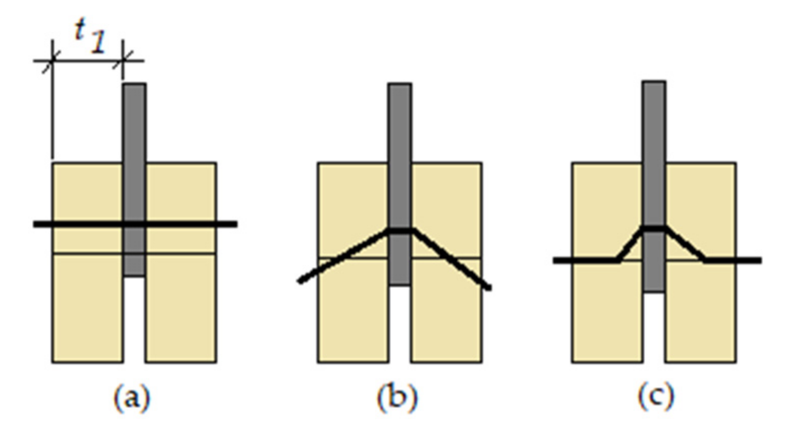
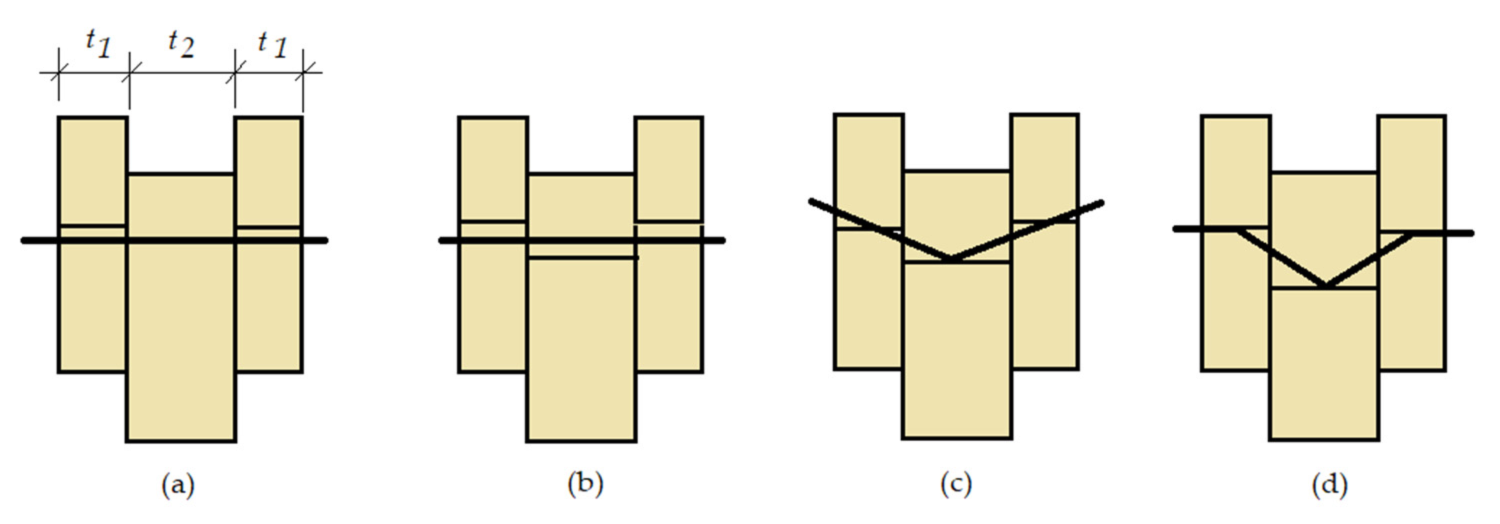
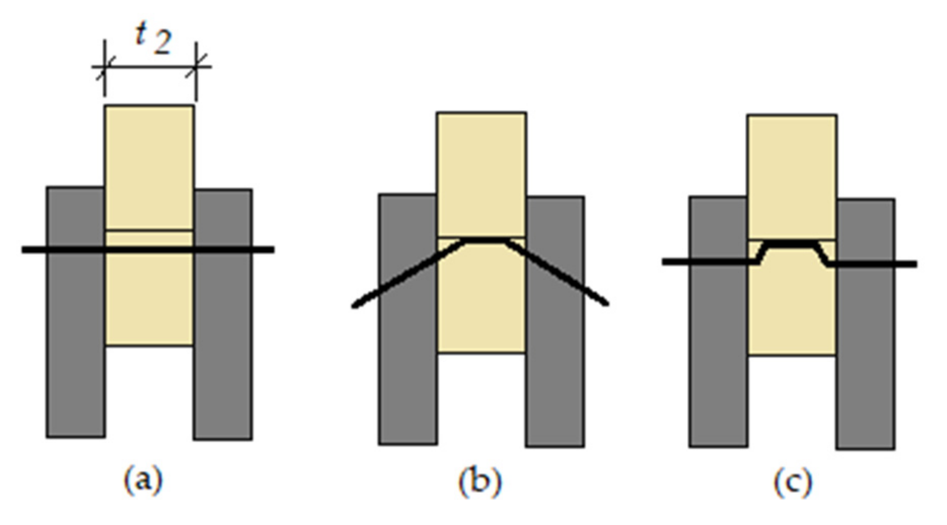
3. Simplified Equations in Designed Timber Connections

The yield strength, the embedment strength, and the withdrawal strength of the fastener must be considered to determine the characteristic load-carrying capacity of the dowelled connections [18]. Theoretical models were developed to define the characteristic values of the connection load-carrying capacity, based on the material properties and the dimensions of the connection [20,21]. Eurocode 5 part 1-1 [18] provides simplified equations for calculating the load-carrying capacity of single-shear and double-shear plane in different connection types. In double-shear plane connections, the resistance of each shear plane must be determined. The basic prerequisite for the calculation is the symmetrical arrangement of the connection [18].
For the dimensioning of timber connections under double shear, it is intended to determine the main dimensions (width, height, thickness of the wood elements and steel plate, minimum spacing and edge/end distances between the dowels and the wooden plate). The number of dowels is an important parameter in the connection design with the arrangement by rows and columns [3,5,6,7]. Connections are verified to satisfy double shear, considering several potential failure modes. This will depend on the length of penetration of the dowel into elements, the strength to localized crushing, the dowel diameter, and the characteristic yield moment of the fastener.
During this study, different parameters are considered for the three studied connections: tensile applied load Fd, dowel diameter d, the wooden board thickness t1 (smaller thickness of the wood side member or the penetration depth), t2 (thickness of the wood middle member) and the steel plate thickness ts. To calculate the dimension of each connection type, the load was considered as parallel to the grain direction, [24,25]. The present study compares the performance of the three different types of connections, depending on the different variables, and based on the work previously started by the authors [25,26,27,28].
The following equations are considered for connection for double-shear, where the dowel diameter must be greater than 6 mm and less than 30 mm. According to Eurocode 5, part 1-1 [18], the design tensile strength along the grain f t , 0 , d , must be equal or greater than the design tensile stress along the grain σ t , 0 , d . The tensile strength f t , 0 , d , defined by Equation (1), represents a reduced value of its characteristic value along the wood grain f t , 0 , k , due to the application of two safety factors: the modification factor for load duration and moisture content k m o d , considered equal to 0.6 for permanent load action, and the partial factor for material property γ M equal to 1.25 according to Eurocode 5 part 1-1 [18].
f t , 0 , d = f t , 0 , k   k m o d γ M
Considering A s the cross-section of the member, the design tensile stress along the grain σ t , 0 , d is calculated using Equation (2), Eurocode 5, part 1-1 [18].
σ t , 0 , d = F d A s
For symmetrical connections in double shear, the characteristic load-carrying capacity per shear plane and fastener F v , R k , is obtained according with Eurocode 5 part 1-1 [18]. These equations are based on a theory developed by Johansen in 1949 [10,24,29].
Johansen was the first to describe the mechanical behavior of this type of connections [30]. His theory characterizes three distinct failure modes but does not consider potential brittle modes [29], only considers ductile failure modes [14]. The equations derived by Johansen [10] for connection strength are dependent on geometry, fastener strength, wood embedment strength, and bending strength [24]. In the derivation of these equations, however, the friction forces between the connected members were ignored, as well as the withdrawal resistance of the fasteners [24]. To include these effects, the characteristic load-carrying capacity of a fastener is given by the Equations (3)–(6) [10,22,24], according to Eurocode 5 part 1-1 [18].
For symmetrical connections in double shear, the characteristic load-carrying capacity per shear plane and fastener will be the minimum value of these three equations, and the failure mode will be the mode associated with each equation, Figure 1, Figure 2 and Figure 3.
Using all the simplified equations proposed from Eurocode 5, part 1-1 [18], the characteristic load-carrying capacity per shear plane and fastener F v , R k , in case the timber connection has an internal steel plate of any thickness (W-S-W) are given by the Equation (3).
F v , R k = m i n (3a) f h , 1 , k   t 1   d (3b) f h , 1 , k   t 1   d   2 + 4 M y , R k f h , R k   d   t 1 2 1 + F α x , R k 4 (3c) 2.3   M y , R k   f h , 1 , k   d + F α x , R k 4
For the double shear connection with a steel plate of any thickness as the central member, the different failure modes are represented in Figure 1, relative to the characteristic load-carrying capacity per shear plane and fastener, calculated by the Equation (3a–c). The ratio between the side width and the dowel diameter is often used to explain the failure mode of a connection [27]. In Figure 1 the failure mode in (a) represents embedment of the wood, in (b) it represents the bending of the fastener and in (c) it is the combination of the previously mentioned modes [18].
For a timber-to-timber connection (W-W-W) with dowel in double shears, the characteristic load-carrying capacity is given by the Equation (4).
F v , R k = m i n (4a) f h , 1 , k   t 1   d (4b) 0.5   f h , 2 , k   t 2   d (4c) 1.05   f h , 1 , k   t 1   d 2 + β   2 β 1 + β + 4 β 2 + β M y , R k f h , R k   d   t 1 2 β + F α x , R k 4 (4d) 1.15 2 β 1 + β   2 M y , R k   f h , 1 , k   d + F α x , R k 4
The four modes of failure of the timber-to-timber connections are illustrated in Figure 2, which correspond, respectively, to the four characteristic load-carrying capacities given by the Equation (4a–d). The failure mode (a) represents the bearing failure of the edge members, in (b) it represents the bearing failure of the central member, in (c) it represents the simultaneous formation of the plastic hinge on the fastener inside the central member and bearing failure of all the members and (d) it represents the simultaneous plastic hinge formation in the fastener within all members and bearing failure of all members [18,24].
For a steel-to-timber connection (S-W-S) the characteristic load-carrying capacity depends on the thickness of the steel plates, Eurocode 5 part 1-1 [18], which are given by the Equations (5) and (6). The thickness of steel plates less than or equal to 0.5 multiplied by the dowel diameter are classified as thin plates, and greater than or equal to the diameter are classified as thick plates [18]. The characteristic load-carrying capacity of the connections with steel plate thickness between a thin and a thick plate must be calculated by linear interpolation between the previous values [18].
For a double shear connection, the characteristic load-carrying capacity using thick steel plates as the outer members is given by the Equation (5):
F v , R k = m i n (5a) 0.5 f h , 2 , k   t 2   d (5b) 2.3 2 M y , R k   f h , 2 , k   d + F a x , R k 4
In the studied connections, the external steel plate has a thickness equal to 3 mm, being classified as a thin plate. For this condition, when steel plates are the outer members of a double shear connection, the characteristic load-carrying capacity is obtained using the Equation (6).
F v , R k = m i n (6a) 0.5 f h , 2 , k   t 2   d (6b) 1.15 2 M y , R k   f h , 2 , k   d + F a x , R k 4
where: f h , i , k ( f h , 1 , k or f h , 2 , k ) is the characteristic embedment strength in timber member i; M y , R k is the characteristic yield moment of the fastener, β is the ratio between the embedment strength of the members considered equal to 1, and F α x , R k represents the characteristic axial withdrawal capacity of the fastener, according to Eurocode 5 part 1-1 [18].
The three different failures modes are shown in Figure 3. The failure mode in (a) represents the wood embedment obtained from Equations (5a) and (6a), the failure mode (b) is the fastener bending from Equation (5b), and failure mode (c) is the combination of the previous failure modes obtained from Equation (6b), [18].
The value of the characteristic embedment strength in the timber member i parallel to the grain with pre-drilled holes is obtained due to the value of the dowel diameter between 6 mm and 30 mm, and the characteristic wood density ρ k , as defined in Equation (7).
f h , 1 , k = f h , 2 , k = 0.082 1 0.01   d   ρ k
The value of M y , R k is calculated according to the dowel diameter d, and its material characteristic tensile strength f u , k , [25].
M y , R k = 0.3   f u , k   d 2 , 6
After calculating the value of F v , R k , it is necessary to determine the design value of the characteristic load-carrying capacity, which is obtained from the Equation (9), in which two safety factors are considered, defined in accordance with Eurocode 5 part 1-1 [18].
F v , R d = F v , R k   k m o d γ M
Finally, with the calculation from F v , R d , it is possible to obtain the number of dowels, which is given by Equation (10), [25].
N F d F v , R d
To reduce the risk of failure modes, the minimum edge, and spacing criteria for connections with dowel were calculated [17]. The arrangement between dowels is according to the calculated spacing, following the Equations (11)–(14): parallel to the fastener grain and within a row a 1 , perpendicular to the grain and between rows a 2 , the distance between the fasteners and the loaded end a 3 , t and unloaded edge a 4 , c , which varies according to the dowel diameter [18,25]. The parameter α represents the angle, between the applied tensile load and the wood grain direction.
a 1 =   3 + 2 c o s   α     d
a 2 = 3 d
a 3 , t = m a x 7 d ;   80   mm
a 4 , c = 3 d
According to Eurocode 5 part 1-1 [18], the arrangements of the dowels in the studied connections are represented in Figure 4.

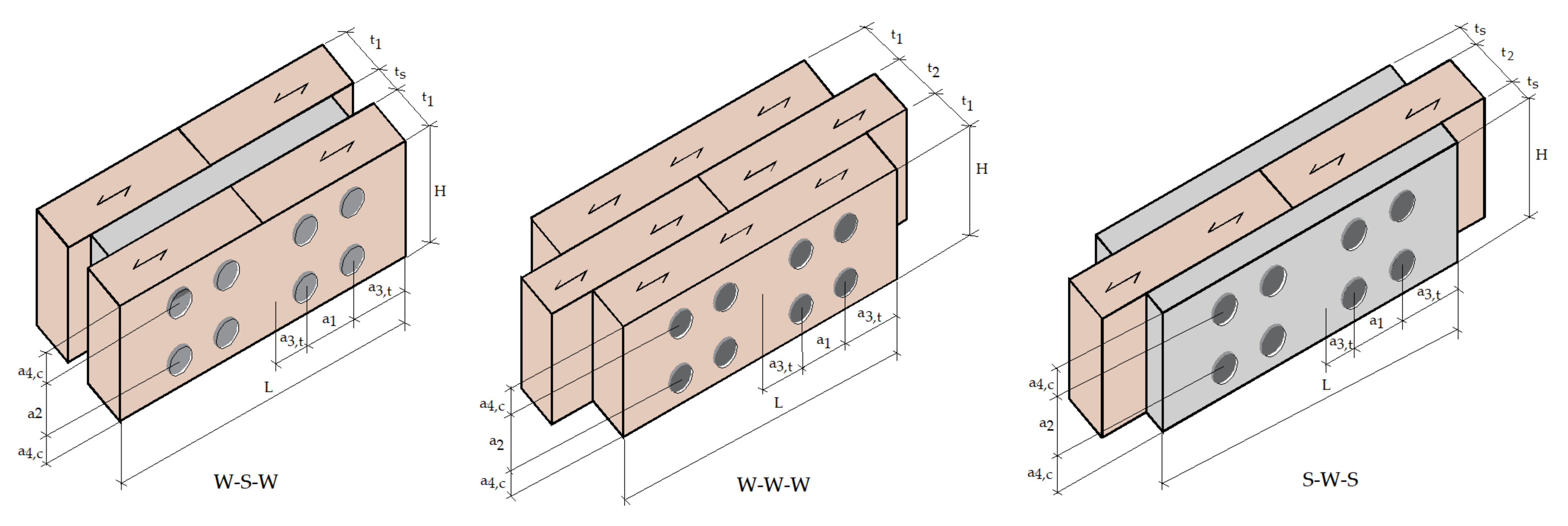
4. Parametric Study of the Connections

Figure 4 shows the three connections in study, with all parameters involved in the project.
For the parametric study, three dowel diameters (8, 10, and 12 mm), three applied tensile loads (10, 15, and 20 kN), and three wood materials (GL20H, GL24H, and GL32H) [28] were considered.

4.1. Design Parameters

The results are presented in Table 2, Table 3 and Table 4, with all the different parameters to check the load-carrying capacity of the connection, the cross-section, the number of fasteners, and the minimum spacing at the edges, according to Eurocode 5, part 1-1 [18].
The number of calculated dowels were distributed in rows and columns, with 3 considered the fixed number of columns. In addition, the thickness of the wooden board t1 and t2 was chosen, [18]. For unprotected connections with side members of wood, the thickness of the members must be greater than 45 mm, in accordance with Eurocode 5 part 1-2 [30]. The thickness of the steel plate ts inside the connection was considered equal to 6 mm and on the outside of the connection equal to 3 mm.
A total of 81 timber connections were studied, 27 by type of connection.
Table 2, Table 3 and Table 4 show all the necessary design parameters for all different types of timber connections, namely: dowel diameter and length, dowel arrangement and distances, connection member dimensions and the design characteristic load-carrying per shear plane and fastener. In these tables, the results are presented considering wooden members equal to 45 mm. This parametric study makes it possible to establish the relationship between the strength and wood density, the dowel diameter, and the applied tensile load, to establish the required number of fasteners.

4.2. Discussion

To identify additional design considerations, different values were introduced for the wooden board thickness, and the results allow verifying the corresponding failure mode for each situation. Table 5 presents the correspondent design equation, which defines the number of dowels, for each wood species and dowel diameter, using different wooden board thicknesses t1 and t2. The failure mode associated with each design equation is also identified.
The parametric study shows a linear correlation between all design parameters for each type of timber connections. This shows that the number of dowels increased for small diameters and lower strength and density of wood.
In general, when using larger dowel diameters, the wood density effect is not relevant. The strength and density of wood exert a relative influence when connections have small dowel diameters. In all connections, there is a considerable increase in shear strength for higher dowel diameters, wood density and strength.
But as the dowel diameter increases, the hole connection also increases, which weakens the resistance of the cross-section and allows different failure modes to occur, as reported by [12].
A wooden board thickness less than or equal to 45 mm influences the required number of dowels. For wooden thicknesses greater than 45 mm, the calculated number of dowels is not dependent on this parameter, as indicated in the design equations.
In W-S-W connections with side members smaller than 45 mm, the failure model represents the bending of the fastener, but when the wooden thickness increases, the failure model is represented in the wood embedment in combination with the bending of the fastener. The failure mode is independent of the wood member thickness. This fact is evidenced by the failure mode determined with the minimum value of the characteristic load-carrying capacity per shear plane and fastener given by Equations (3), which varies according to the dowel diameter, wood strength, and density.
In W-W-W connections, the calculation of the number of dowels does not depend on the thickness of the wooden elements, when considering thicknesses equal to or greater than 45 mm. This fact is supported by the same failure mode, identified from the minimum characteristic load-carrying capacity. The failure mode starts with the simultaneous plastic hinge formation on the fastener inside the wood central member and bearing failure of all members, in connections with larger diameters and thicknesses of the elements equal to 45 mm. For elements with thickness higher than 45 mm the failure mode appears simultaneously with a plastic hinge formation in the fastener within all members and bearing failure of all members. However, considering elements with thicknesses lower than 45 mm, the failure mode is influenced by the thicknesses of both wood members and represented by the bearing failure of the central member.
In S-W-S connections, the number of dowels is independent of the thickness of the wooden elements and has the same failure mode, for thicknesses equal to or greater than 45 mm. This failure mode represents the embedment of the wood, bending of the fastener and failure, both together. However, using wooden members with a thickness of less than 45 mm, the number of dowels depends on the wooden thickness, as shown in the calculated results. The failure mode represents the wood embedment, regardless of the dowel diameter or wood material.
The results show that the W-S-W connections need the least number of dowels according to the design equations, that is, the GL32H connection with lesser member thickness needs the least number of dowels, when using a diameter equal to 12 mm.
On the other hand, S-W-S connections require a greater number of dowels when compared to the other connection types, especially the connection GL20H with a smaller dowel diameter. As the diameter of the dowel increases, the hole size in the wooden members also increases, which can produce a concentration of stress around the hole.

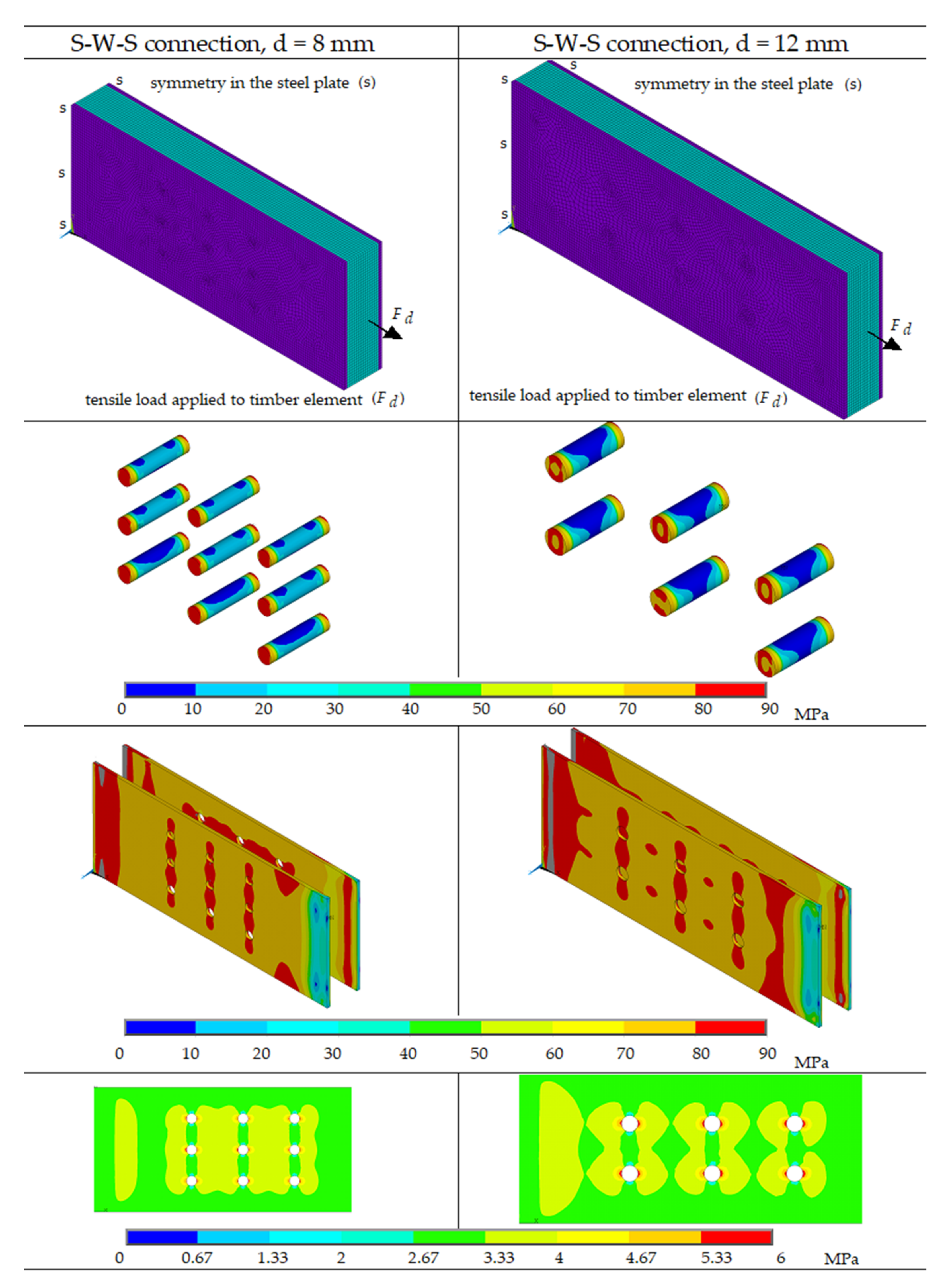
4.3. Numerical Simulation on S-W-S Connection (t2 = 27.5 mm, d = 8 and 12 mm)

In accordance with the previous conclusion, a numerical simulation is included to verify the effect of the dowel diameter in S-W-S connections, where the number of the dowels is greater, with t2 equal to 27.5 mm and wood GL20H.
This analysis is ongoing research, where the main objective is to evaluate the increase in the hole connection and its effect on the strength of the cross-section. Two numerical simulations are presented for dowels diameters equal to 8 and 12 mm.
A numerical and structural 3D model was developed using ANSYS 2020 R2 ®, using a solid finite element with 8 nodes and three degrees of freedom per node, with element edge equal to 2 mm. Previous mesh convergence tests were performed to minimize the computational error.
The numerical model aims to simulate an incremental tensile load applied to the connection. To solve the problem and the convergence, Newton’s method was used. Based on the geometric model and its symmetry, typical boundary conditions were applied. Due to the contact interface between wooden and steel elements, a coefficient of static friction equal to 0.3 was considered [5].
The material properties considered are described in Section 2 of this work. The mechanical model is based on the von Mises criterion for both materials, where the stress-strain curve of steel and a stress-strain curve parallel to the grain of the wood material GL20H were introduced. The mesh model, the load carrying capacity in each connection and the stress distribution in all the involved elements are represented in Figure 5.
The results between the two numerical models show that the stress levels to which they are subjected are different.
In connection with a dowel diameter equal to 8 mm, the number of dowels is equal to 9 and in connection with a diameter equal to 12 mm, only 6 dowels are required.
The model with a diameter equal to 8 mm, presents higher stresses in the steel plate and dowels.
On the other hand, in the wooden element, the normal stresses are more homogeneous and around the holes tend to smaller is comparison with the other model. This may mean that, although the number of dowels is greater, it does not affect the level of stresses installed in the wood.
Alternatively, in connections with larger dowel diameters, the level of stress installed around the hole in the wooden element is more pronounced and higher, which facilitates the stress concentration and the wood embedment failure mode.
The characteristic load-carrying capacity per shear plane and fastener obtained in the numerical simulation was 2972 N for the connection with a dowel diameter equal to 8 mm, whose value calculated with Equation (6a) was equal to 2821 N.
For the model with a dowel diameter of 12 mm, the numerical value was 5083 N and 4048 N using Equation (6a).
With these conclusions, it means that the use of alternative methodologies can complement the use of simplified design calculations.

5. Conclusions

In this work, the methodologies to evaluate the safe design, for three types of timber connections in double shear, which is proposed by Eurocode 5, part 1-1 [18], are presented. The influence of design parameters is analyzed by studying many doweled connections.
The connection design depends on the failure mode, being defined for each type of timber connection. Connection characteristics can be established with test results or design standards. The results obtained are extremely useful to achieve the typical dimensions needed for any type of timber connection and, at the same time, to verify the influence of the strength and density of the wood.
The following general conclusions can be drawn:
-
The number of dowels increases with the tensile load.
-
Smaller dowel diameters have a greater influence on the number of fasteners.
-
The number of dowels increases with lower wood density properties.
-
The number of dowels increases with lower strength properties of wood.
-
The influence of the thickness of the wood elements on the number of dowels is negligible for values equal to or greater than 45 mm.
Numerical simulations were very relevant. New models can be used to verify other types of connections. The distribution of stresses around the connection holes is an important parameter to be controlled, even in connections properly designed in accordance with Eurocode guidelines.
Based on the presented work, one can define the need for more research related to the study of the different connection configurations and fasteners in use. Furthermore, it is intended to compare the effect of strength and density of wood in single shear connections.

Author Contributions

Conceptualization, E.M.M.F.; methodology, H.M.L.; validation, P.A.S.L., L.D.S.S. and V.S.B.S.; investigation, P.A.S.L., L.D.S.S. and V.S.B.S.; writing—original draft preparation, E.M.M.F.; writing—review and editing, E.M.M.F. and H.M.L.; supervision, E.M.M.F. All authors have read and agreed to the published version of the manuscript.

Funding

This research received no external funding.

Institutional Review Board Statement

Not applicable.

Informed Consent Statement

Not applicable.

Data Availability Statement

Not applicable.

Conflicts of Interest

The authors declare no conflict of interest.

References

  1. Amorim, F.; João, N. Projecto de Estruturas de Madeira; Publindústria, Edições Técnicas: Porto, Portugal, 2009; pp. 1–35. [Google Scholar]
  2. ASCE. Mechanical Connections in Wood Structures; Manual and Reports on Engineering Practice N. 84; American Society of Civil Engineers: New York, NY, USA, 1995. [Google Scholar]
  3. Abderrahim, A.; Elza, M.M.F.; Alvear, P.M.D. W-W-W Connections in Double-Shear at Ambient Temperature: Effect of the Applied Tensile Load and Dowels Diameter. In Proceedings of the 6th International Conference on Integrity-Reliability-Failure, Porto, Portugal, 22–26 July 2018. [Google Scholar]
  4. Silva, L.D.S. Wood-Steel Connections (W-S-W) in Double-Shear at Room and High Temperatures. Master’s Thesis, Instituto Politécnico do Porto, Porto, Portugal, 2019. [Google Scholar]
  5. Fernando, M.M.; Elza, M.M.F.; Jorge, L.N.G. Load-Carrying Capacity in W-S-W Connections in Double-Shear at Ambient Temperature. In Proceedings of the 1st Iberic Conference on Theoretical and Experimental Mechanics and Materials/11th National Congress on Experimental Mechanics, Porto, Portugal, 4–7 November 2018. [Google Scholar]
  6. Fonseca, E.M.M.; Leite, P.A.S. Fire design of wood connections loaded in shear. MATTER Int. J. Sci. Technol. 2019, 5, 68–84. [Google Scholar] [CrossRef] [Green Version]
  7. Peng, L. Performance of Heavy Timber Connections in Fire. Ph.D. Thesis, Carleton University, Ottawa, ON, Canada, 2010. [Google Scholar]
  8. Ruben, D.A.R.M.; Elza, M.M.F. Double-Shear W-S-W Connections at Ambient Temperature, with Different Applied Tensile Loads and Steel Dowels Diameter. In Proceedings of the 6th International Conference on Integrity-Reliability-Failure, Porto, Portugal, 22–26 July 2018. [Google Scholar]
  9. Miao, C.; Fernando, D.; Heitzmann, M.T.; Bailleres, H. GFRP-to-timber bonded joints: Adhesive selection. Int. J. Adhes. Adhes. 2019, 94, 29–39. [Google Scholar] [CrossRef]
  10. Porteous, J.; Kermani, A. Structural Timber Design to Eurocode 5, 2nd ed.; Wiley-Blackwell Publishing: New York, NY, USA, 2007; pp. 385–423. [Google Scholar]
  11. Forest Products Laboratory. Wood Handbook—Wood as an Engineering Material; General Technical Report FPL-GTR-190, Centennial Edition; Department of Agriculture, Forest Service, Forest Products Laboratory: Madison, WI, USA, 2010; 508p. [Google Scholar]
  12. Domínguez, M.; Fueyo, J.G.; Villarino, A.; Anton, N. Structural Timber Connections with Dowel-Type Fasteners and Nut-Washer Fixings: Mechanical Characterization and Contribution to the Rope Effect. Materials 2022, 15, 242. [Google Scholar] [CrossRef] [PubMed]
  13. Chybinski, M.; Polus, L. Mechanical Behaviour of Aluminium-Timber Composite Connections with Screws and Toothed Plates. Materials 2022, 15, 68. [Google Scholar] [CrossRef] [PubMed]
  14. Lokaj, A.; Dobes, P.; Sucharda, O. Effects of Loaded End distance and Moisture Content on the Behavior of Bolted Connections in Squared and Round Timber Subjected to Tension Parallel to the Grain. Materials 2020, 13, 5525. [Google Scholar] [CrossRef] [PubMed]
  15. Peng, L.; Hadjisophocleous, G.; Mehaffey, J.; Mohammad, M. On the Fire Performance of Double-shear Timber Connections. Fire Saf. Sci. 2011, 10, 1207–1218. [Google Scholar] [CrossRef]
  16. Frangi, A.; Erchinger, C.; Fontana, M. Experimental fire analysis of steel-to-timber connections using dowels and nails. Fire Mater. 2009, 34, 1–19. [Google Scholar] [CrossRef]
  17. Fonseca, E.M.M.; Leite, P.A.S.; Silva, L. Wood Connections Under Fire Conditions Protected with Gypsum Plasterboard Types A and F. In Advances in Fire Safety Engineering; PilotoJoão, P.A.G., Valdir, P.R., Silva, P., Eds.; Springer Nature: Cham, Switzerland, 2020; Volume 1, pp. 93–106. [Google Scholar]
  18. European Committee for Standardization. Eurocode 5: Design of Timber Structures. Part 1-1: General Common Rules and Rules for Buildings; BSI: Brussels, Belgium, 2004. [Google Scholar]
  19. Johansson, C.J. Grading of timber with respect to mechanical properties. In Timber Engineering; Thelandersson, S., Larsen, H.J., Eds.; Wiley: London, UK, 2003. [Google Scholar]
  20. Green, D.W.; Winandy, J.E.; Kretschmann, D.E. Mechanical Properties of Wood. In Wood Handbook; Department of Agriculture, Forest Service, Forest Products Laboratory: Madison, WI, USA, 1999; 463p. [Google Scholar]
  21. British Standards Institution. Timber Structures. Glued Laminated Timber. Strength Classes and Determination of Characteristic Values; BSI: London, UK, 1999. [Google Scholar]
  22. Hasslacher Norica Timber. Glued Laminated Timber. The Engineering Timber Beam, Germany. Available online: https://www.hess-timber.com/en/products/glued-laminated-timber/ (accessed on 29 September 2021).
  23. European Committee for Standardization. Eurocode 3: Design of Steel Structures. Part 1-1: General Rules and Rules for Buildings; BSI: London, UK, 2005. [Google Scholar]
  24. Gocál, J. Load Carrying Capacity of Metal Dowel Type Connections of Timber Structures. Civ. Environ. Eng. 2014, 10, 51–60. [Google Scholar] [CrossRef] [Green Version]
  25. Martins, D.A.R.; Fonseca, E.M.M. Fire Behaviour of Protected W-S-W Connections with a Steel Plate as the Central Member and Different Dowels Diameter. MATTER Int. J. Sci. Technol. 2018, 4, 60–78. [Google Scholar] [CrossRef]
  26. Fonseca, E.M.M.; Silva, L.; Leite, A.S.P. Fire safety of wood-steel connections. In Proceedings of the 4th International Conference on Numerical and Symbolic Computation Developments and Applications—Developments and Applications, Porto, Portugal, 11–12 April 2019. [Google Scholar]
  27. Silva, V.; Fonseca, E.M.M. Design of steel-wood-steel connections at the ambient and elevated temperatures. JCAMECH 2021, 52, 85–101. [Google Scholar]
  28. Fonseca, E.M.M.; Silva, L.; Leite, P.A.S. Numerical model to predict the effect of wood density in wood-steel-wood connections with and without passive protection under fire. J. Fire Sci. 2020, 38, 122–135. [Google Scholar] [CrossRef]
  29. Dorn, M.; de Borst, K.; Eberhardsteiner, J. Experiments on dowel-type timber connections. Eng. Struct. 2013, 47, 67–80. [Google Scholar] [CrossRef] [Green Version]
  30. European Committee for Standardization. Eurocode 5: Design of Timber Structures. Part 1-2: General Structural Fire Design; BSI: Brussels, Belgium, 2004. [Google Scholar]
Figure 1. Steel-to-timber connections in double shear (W-S-W): (a) wood embedding; (b) fastener bending; (c) combination of failure modes.
Applsci 12 01701 g001
Figure 2. Timber-to-timber connections in double shear (W-W-W): (a) bearing failure of the edge members; (b) central member bearing failure; (c) plastic hinge on the fastener inside the central member and bearing failure of all the members; (d) plastic hinges on the fastener and bearing failure on all members.
Applsci 12 01701 g002
Figure 3. Steel-to-timber connections in double shear (S-W-S): (a) wood embedding; (b) fastener bending; (c) combination of failure modes.
Applsci 12 01701 g003
Figure 4. Timber connections in study. Wood grain is parallel to the axial direction.
Applsci 12 01701 g004
Figure 5. S-W-S connection (t2 = 27.5 mm, d = 8 and 12 mm).
Applsci 12 01701 g005
Table 1. Mechanical properties for glulam at approximately 12% moisture content [9,20,21].
Mechanical PropertiesGL20HGL24HGL32H
Average parallel-to-grain tensile strength, f t , 0 , k , N/mm21619.225.6
Young’s Modulus, E, N/mm2840011,50014,200
Density, ρ k , kg/m3370420480
Table 2. Design parameters for W-S-W connections.
LoadDowelDowel arrangementDistancesConnection
dimensions
Design tensile stressDesign characteristic load-carrying
kNmmmmmmN/mm2N
FddlengthN RowsN Columnsa1a2a3,ta4,ct2tsHLσt,o,dFv,Rd
GL20H
1089623402480244567248010.242390
109623503080304569052010.243135
129623603684364567257610.243963
1589633402480244569648010.242390
109623503080304569052010.243135
1296236036843645610857610.243963
2089643402480244569648010.242390
1096335030803045612052010.243135
1296236036843645610857610.243963
GL24H
1089623402480244567248012.292661
109623503080304569052012.293468
129623603684364567257612.294357
1589633402480244569648012.292661
109623503080304569052012.293468
1296236036843645610857612.294357
2089633402480244569648012.292661
1096235030803045612052012.293468
1296236036843645610857612.294357
GL32H
1089623402480244567248016.382986
109613503080304569052016.383868
129613603684364567257616.384828
1589633402480244569648016.382986
109623503080304569052016.383868
1296136036843645610857616.384828
2089633402480244569648016.382986
1096235030803045612052016.383868
1296236036843645610857616.384828
Table 3. Design parameters for W-W-W connections.
LoadDowelDowel arrangementDistancesConnection dimensionsDesign tensile stressDesign characteristic load-carrying
kNmmmmmmN/mm2N
FddlengthN RowsN Columnsa1a2a3,ta4,ct1t2HLst,o,dFv,Rd
GL20H
108135334024802445457244010.241908
10135235030803045459048010.242568
121351360368436454510852010.243216
158135434024802445459644010.241908
10135235030803045459048010.242568
121352360368436454510852010.243216
2081355340248024454512044010.241908
101353350308030454512048010.242568
121352360368436454514452010.243216
GL24H
108135334024802445457244012.292033
10135235030803045459048012.292851
12135136036843645457252012.293550
158135434024802445459644012.292033
10135235030803045459048012.292851
121352360368436454510852012.293550
2081355340248024454512044012.292033
101353350308030454512048012.292851
121352360368436454510852012.293550
GL32H
108135234024802445457244016.382173
10135235030803045459048016.383188
12135136036843645457252016.383950
158135334024802445459644016.382173
10135235030803045459048016.383188
121352360368436454510852016.383950
2081354340248024454512044016.382173
101353350308030454512048016.383188
121352360368436454510852016.383950
Table 4. Design parameters of three for S-W-S connections.
LoadDowelDowel arrangementDistancesConnection
dimensions
Design tensile stressDesign characteristic load-carrying
kNmmmmmmN/mm2N
FddlengthN RowsN Columnsa1a2a3,ta4,ct2tsHLσt,o,dFv,Rd
GL20H
1085123402480244537248010.241735
105123503080304539052010.242564
1251236036843645310857610.243180
1585133402480244539648010.241735
105123503080304539052010.242564
1251236036843645310857610.243180
20851434024802445312048010.241735
1051335030803045312052010.242564
1251336036843645314457610.243180
GL24H
1085123402480244537248012.291846
105123503080304539052012.292729
1251136036843645310857612.293600
1585133402480244539648012.291846
105123503080304539052012.292729
1251236036843645310857612.293600
20851434024802445312048012.291846
1051335030803045312052012.292729
1251236036843645314457612.293600
GL32H
1085123402480244537248016.381974
105123503080304539052016.382917
1251136036843645310857616.384005
1585133402480244539648016.381974
105123503080304539052016.382917
1251236036843645310857616.384005
20851434024802445312048016.381974
1051335030803045312052016.382917
1251236036843645314457616.384005
Table 5. Parametric study in three types of timber connections.
Woodd,
mm
W-S-W
t1 =
27.5 mm
Failure mode
Equation
t1 =
45 mm
Failure mode
Equation
t1 =
62.5 mm
Failure mode
Equation
t1 =
80 mm
Failure mode
Equation
GL20H8N = 0.685 × Fd(3b)N = 0.418 × Fd(3b)N = 0.371 × Fd(3c)N = 0.371 × Fd(3c)
10N = 0.522 × Fd(3b)N = 0.319 × Fd(3b)N = 0.251 × Fd(3c)N = 0.251 × Fd(3c)
12N = 0.413 × Fd(3b)N = 0.253 × Fd(3b)N = 0.183 × Fd(3c)N = 0.183 × Fd(3c)
GL24H8N = 0.615 × Fd(3b)N = 0.376 × Fd(3b)N = 0.348 × Fd(3c)N = 0.348 × Fd(3c)
10N = 0.472 × Fd(3b)N = 0.288 × Fd(3b)N = 0.235 × Fd(3c)N = 0.235 × Fd(3c)
12N = 0.376 × Fd(3b)N = 0.230 × Fd(3b)N = 0.171 × Fd(3c)N = 0.172 × Fd(3c)
GL32H8N = 0.548 × Fd(3b)N = 0.335 × Fd(3b)N = 0.325 × Fd(3c)N = 0.325 × Fd(3c)
10N = 0.423 × Fd(3b)N = 0.259 × Fd(3b)N = 0.220 × Fd(3c)N = 0.220 × Fd(3c)
12N = 0.339 × Fd(3b)N = 0.207 × Fd(3b)N = 0.160 × Fd(3c)N = 0.160 × Fd(3c)
Woodd,
mm
W-W-W
t1 = t2 =
27.5 mm
Failure mode
Equation
t1 = t2 =
45 mm
Failure mode
Equation
t1 = t2 =
62.5 mm
Failure mode
Equation
t1 = t2 =
80 mm
Failure mode
Equation
GL20H8N = 0.679 × Fd(4b)N = 0.524 × Fd(4d)N = 0.524 × Fd(4d)N = 0.524x Fd(4d)
10N = 0.555 × Fd(4b)N = 0.389 × Fd(4c)N = 0.355 × Fd(4d)N = 0.355 × Fd(4d)
12N = 0.473 × Fd(4b)N = 0.311 × Fd(4c)N = 0.258 × Fd(4d)N = 0.258 × Fd(4d)
GL24H8N = 0.618 × Fd(4b)N = 0.492 × Fd(4d)N = 0.492 × Fd(4d)N = 0.492 × Fd(4d)
10N = 0.489 × Fd(4b)N = 0.351 × Fd(4c)N = 0.333x Fd(4d)N = 0.333 × Fd(4d)
12N = 0.417 × Fd(4b)N = 0.282 × Fd(4c)N = 0.243 × Fd(4d)N = 0.243 × Fd(4d)
GL32H8N = 0.559 × Fd(4b)N = 0.460 × Fd(4d)N = 0.460 × Fd(4d)N = 0.460 × Fd(4d)
10N = 0.427 × Fd(4b)N = 0.314 × Fd(4c)N = 0.311 × Fd(4d)N = 0.311 × Fd(4d)
12N = 0.365 × Fd(4b)N = 0.253 × Fd(4c)N = 0.227 × Fd(4d)N = 0.227 × Fd(4d)
Woodd,
mm
S-W-S
t2 =
27.5 mm
Failure mode
Equation
t2 =
45 mm
Failure mode
Equation
t2 =
62.5 mm
Failure mode
Equation
t2 =
80 mm
Failure mode
Equation
GL20H8N = 0.738 × Fd(6a)N = 0.576 × Fd(6b)N = 0.576 × Fd(6b)N = 0.576 × Fd(6b)
10N = 0.604 × Fd(6a)N = 0.390 × Fd(6b)N = 0.390 × Fd(6b)N = 0.390 × Fd(6b)
12N = 0.515 × Fd(6a)N = 0.315 × Fd(6a)N = 0.284 × Fd(6b)N = 0.284 × Fd(6b)
GL24H8N = 0.652 × Fd(6a)N = 0.542 × Fd(6b)N = 0.542 × Fd(6b)N = 0.542 × Fd(6b)
10N = 0.533 × Fd(6a)N = 0.367 × Fd(6b)N = 0.367 × Fd(6b)N = 0.367 × Fd(6b)
12N = 0.455 × Fd(6a)N = 0.278 × Fd(6a)N = 0.267 × Fd(6b)N = 0.267 × Fd(6b)
GL32H8N = 0.571 × Fd(6a)N = 0.507 × Fd(6b)N = 0.507 × Fd(6b)N = 0.507 × Fd(6b)
10N = 0.467 × Fd(6a)N = 0.343 × Fd(6b)N = 0.343 × Fd(6b)N = 0.343 × Fd(6b)
12N = 0.398 × Fd(6a)N = 0.250 × Fd(6b)N = 0.250 × Fd(6b)N = 0.250 × Fd(6b)
Publisher’s Note: MDPI stays neutral with regard to jurisdictional claims in published maps and institutional affiliations.

