1. Introduction
The geological structure in Japan is complicated, and excavating a tunnel in a mountainous area often makes construction difficult due to the presence of special ground conditions. Examples of special ground conditions are extremely low ground strength and unconsolidated ground due to ground inhomogeneity such as tunnel fracture zones and initial ground pressure such as expansive ground. When excavating a tunnel under such ground conditions, it is important to predict the impact on the tunnel to prevent its collapse.
Since it has been reported that tunnel excavation work is difficult due to problems caused by ground heterogeneity, we focused on the heterogeneous ground conditions among such special ground conditions and tunnels.
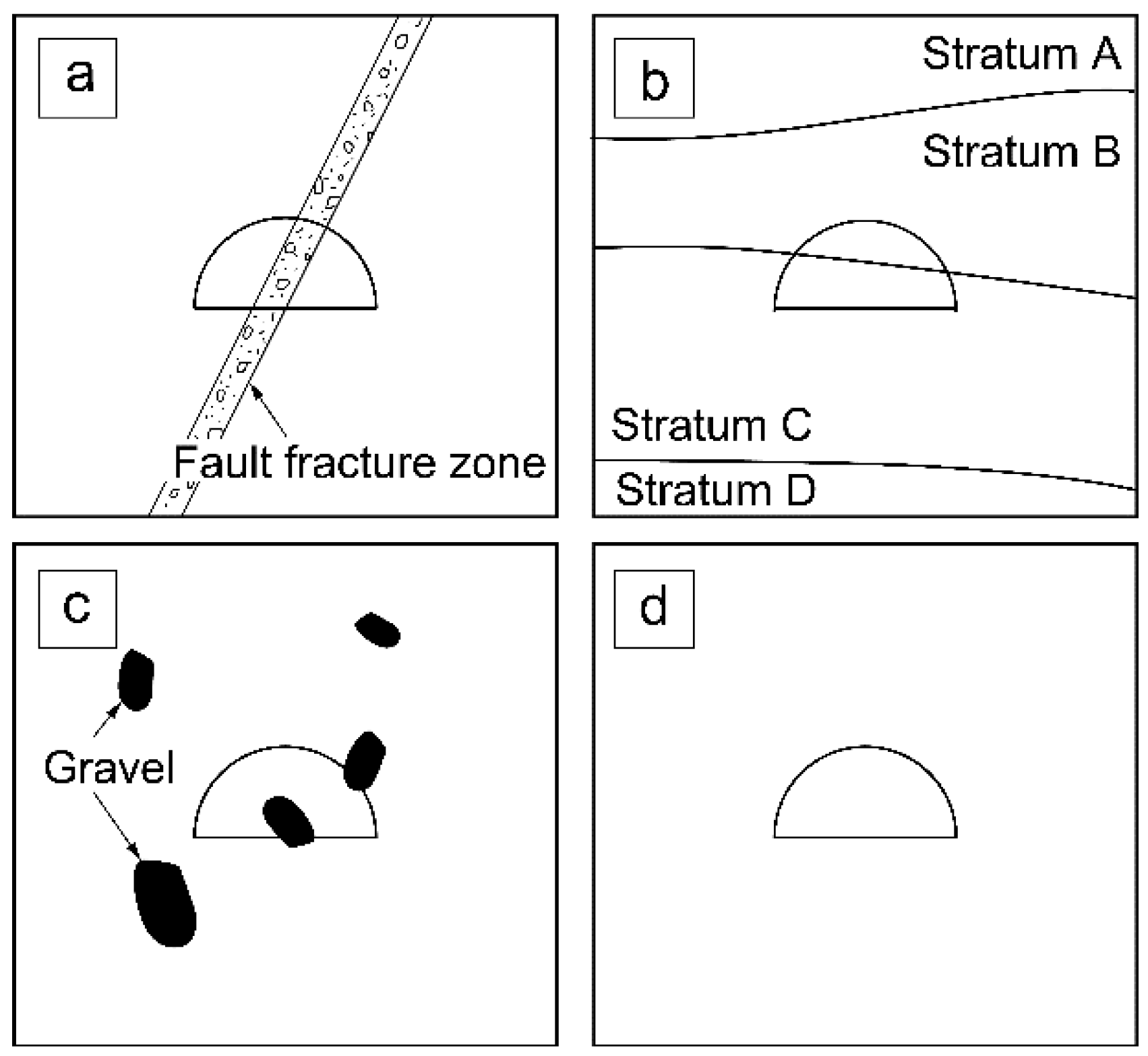
Figure 1 shows the inhomogeneous ground conditions where the tunnel was excavated.
Figure 1a shows the case where a fault exists near the tunnel. In such a case, problems such as sudden spring water, face collapse, and cross-sectional deformation arise.
Figure 1b shows the case where a geological boundary exists near the tunnel. If the geological condition is asymmetrical, an unbalanced pressure may occur in the tunnel support, and if the layer present in the stratum is weak, the tunnel may collapse due to excavation.
Figure 1c shows the case where the sandy ground contains relatively large-sized gravel. If such a condition exists near the tunnel, gravel may fall out due to tunnel excavation, thereby leading to collapse.
Furthermore, as shown in
Figure 1d, clear inhomogeneities such as in
Figure 1a–c are not expected in the same stratum, but weak parts may suddenly appear. If such a part of the ground unexpectedly appears around the tunnel during construction, appropriate support and auxiliary construction methods cannot be applied, and there is a possibility of largescale deformation of the tunnel and, in the worst case, collapse of the tunnel.
If it is possible to identify the problems arising, such as the above-mentioned heterogeneous natural ground, by numerical analysis when drilling a tunnel before its construction, risks during construction can be considered to be greatly reduced.
In this study, we propose tunnel excavation analysis techniques for the natural ground as shown in
Figure 1c. In addition, an example of numerical analysis results is shown, and items to be noted when excavating under such ground conditions are shown.
2. Gravel-Mixed Ground
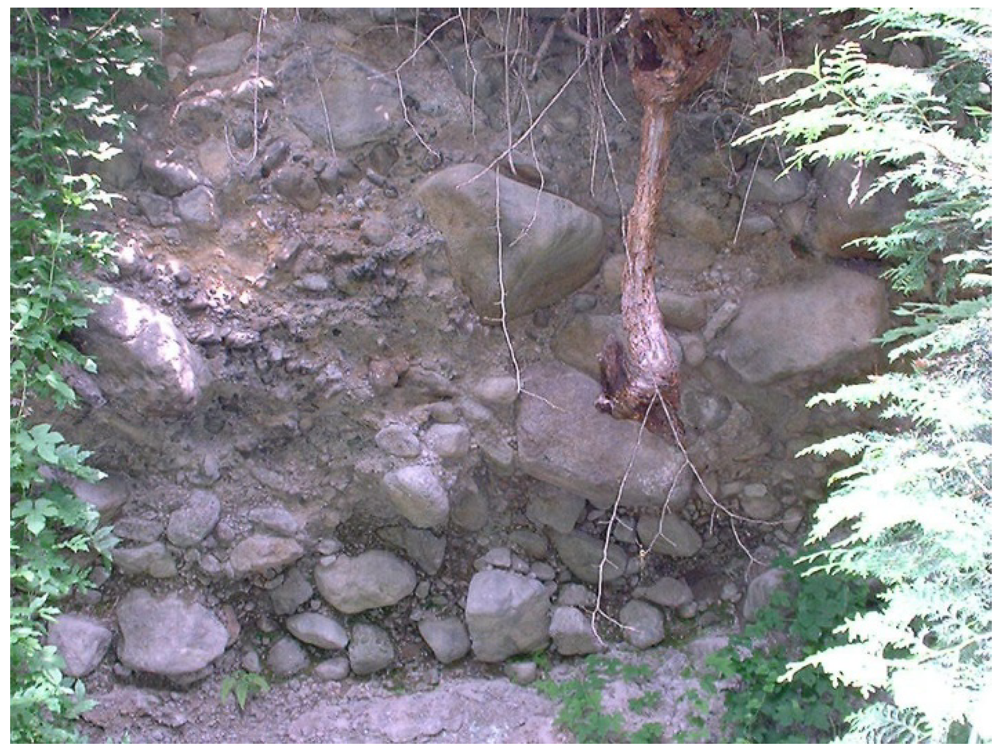
In this study, we assume tunnel construction in a gravel-mixed ground as shown in
Figure 1c. In Japan, pyroclastic rocks consisting of pyroclastic materials, which are solid substances released by volcanic activity, are widely distributed. In addition, there is also a geology in which the debris flow of rocks generated by weathering other than volcanic action becomes debris flow and redeposits. These grounds are named breccia and tuff breccia depending on the grain size of the constituent particles (Fisher [
1]), and hard gravel composed of relatively soft tuff exists in the substrate. When designing a structure on or in such a gravel-mixed ground, understanding the mechanical properties of the gravel-mixed ground is crucial, as shown in
Figure 2. As mentioned above, since it is an inhomogeneous mixture with different intensities, its mechanical properties are often unclear.
For example, Maria et al. [
2] used the finite element method (FEM) and the limit equilibrium method (LEM) to investigate slope stability in gravel-mixed ground. They also show that each material should be considered in gravel mixed ground.
Emad et al. [
3] investigated the slope stability of gravel mixed ground using model tests and finite difference method (FDM). They show the effect of the strength difference of the materials in the gravel mixed ground on the stability of the slope.
Okada et al. [
4] mentioned that when targeting the foundation rock of a nuclear power plant or dam, if the gravel is relatively small compared to the size of the structure, the rock is evaluated as equivalent homogeneous ground. From laboratory tests using artificial conglomerate, the effects of gravel content, gravel-matrix strength ratio, and gravel-matrix interface strength on gravel shear strength were clarified, and a formula for evaluating the strength of the ground mixed with gravel was proposed. Katakawa et al. [
5] created artificial gravel-mixed rocks simulating tuff breccia and tuff andesite and investigated the relationship between the gravel ratio and the mechanical properties of the rock using a uniaxial compression test. According to Kobayashi and Yoshinaka [
6], the stress–strain relationship of gravel-mixed rocks with a gravel content of 40% or less is said to be governed by the deformation characteristics of the substrate, which was determined based on experiments using soft rocks from artificial gravel. It was clarified that the elastic modulus of these rocks can be evaluated as an equivalent elastic modulus. In other words, these research results are classified in “A: Evaluation as equivalent physical properties considering both the gravel part and the substrate part” among the evaluation methods of physical properties of the gravel-mixed ground shown in
Figure 2 regarding the design of the above-ground structure. In addition, this research result suggests that if the gravel content is low, the design should be on the safe side according to “B: Evaluating by the physical properties of the substrate (weak part)”. On the contrary, Okada et al. [
4] stated the need to determine the physical properties of the gravel and substrate parts separately when the gravel is larger than the size of the target above-ground structure and evaluated it as “C: heterogeneous ground”. However, almost no such cases have been reported.
Up to this point, we have focused on above-ground structures, but it is not uncommon to encounter gravel-mixed ground even when constructing mountain tunnels. For example, in the back-ridge tunnel (Asami et al. [
7]), it has been reported that boulders with diameters of 50–150 cm were found in the ground, and the substrate part was loose clay. In addition, other tunnels such as Mito Tunnel (Kitagawa et al. [
8]), Maruko Tunnel (Takase et al. [
9]), Kubohira Tunnel (Amemiya et al. [
10], Nonaka et al. [
11]), Sapporo City Subway’s Tozai Line Departure Kangawa Crossing Construction Zone (Aoki et al. [
12]), Takamine Tunnel (Kazashi et al. [
13]), and Obuki Tunnel (Miyakawa et al. [
14]) have been excavated. It has been reported that the ground contains gravel, and it has also been pointed out that tunnel excavation work is difficult if gravel is distributed near the tunnel. However, as mentioned above, although a certain number of materials were found regarding the construction report when excavating a tunnel in a gravel-mixed ground, no literature focusing on the behavior of gravel during tunnel excavation were found; as such, no predictions could be made.
To perform a mechanical evaluation of the tunnel and the ground around the tunnel using numerical analysis when it is excavated in the gravel-mixed ground, the evaluation method of the gravel-mixed ground for ground structures should be used. In other words, it is necessary to judge which is preferable: “A: Evaluated as equivalent physical properties considering both the gravel part and the substrate part” or “B: Evaluated by the physical properties of the substrate (weak part)”, shown in
Figure 2. Therefore, the items to be considered for the ground when constructing ground structures and tunnels are summarized in this figure. As can be seen, when designing and constructing a ground structure, it is necessary to consider the bearing capacity, sliding resistance, and land subsidence of the ground with respect to the ground structure, while designing and constructing a tunnel structure. When constructing, it is necessary to consider matters related to the displacement (top subsidence/inward subsidence) and ground surface subsidence that occur in the tunnel. Furthermore, considering the safety of the tunnel builder, it is preferable to evaluate the phenomenon of gravel falling out and pushing out due to tunnel excavation and the presence or absence of collapse of the substrate part due to them. To evaluate these, it is important to not assume that the analyzed ground is homogeneous, and when excavating a tunnel in a ground mixed with gravel, it is not the same as the ground on which the above-ground structure is constructed but around the tunnel. Thus, it is necessary to devise a numerical model that can roughly understand the behavior of the gravel and substrate.
4. Analytical Results of the Gravel-Mixed Ground
To clarify how the equivalent mechanical properties of the ground vary depending on the shape and content of gravel, a uniaxial compression-based numerical analysis model was used. The uniaxial compression test is a basic index for judging the mechanical properties of rocks when conducting a mechanical test of the ground material from which a tunnel is excavated, and it has a wide range of applications from soft rocks to unconsolidated rocks (Oshima, [
16]). Therefore, the uniaxial compression numerical analysis model was used. For the numerical analysis, a plane strain model with dimensions discussed previously as shown in
Figure 6 was created, boundary conditions were imposed at the bottom of the model, and then a self-weight analysis was performed. After this analysis converged, an evenly distributed load was applied on the upper part of the model. The equivalent elastic modulus of the model was calculated by dividing the vertical stress generated in the upper center element of the model by the strain calculated from the displacement (sinking amount) generated in the upper central node of the model.
Using triaxial compression test results of a sample simulating conglomerate having a gravel content of 40% or less, Kobayashi [
18] showed that the change in gravel content had little effect on the stress–strain relationship and was dependent on the physical properties of the substrate. When the gravel content reaches 60%, it is affected by the contact between gravel and is not controlled by the physical properties of the substrate. Thus, it is clarified that the gravel content of these intermediate regions (between 40 and 60%) corresponds to those transition regions. Therefore,
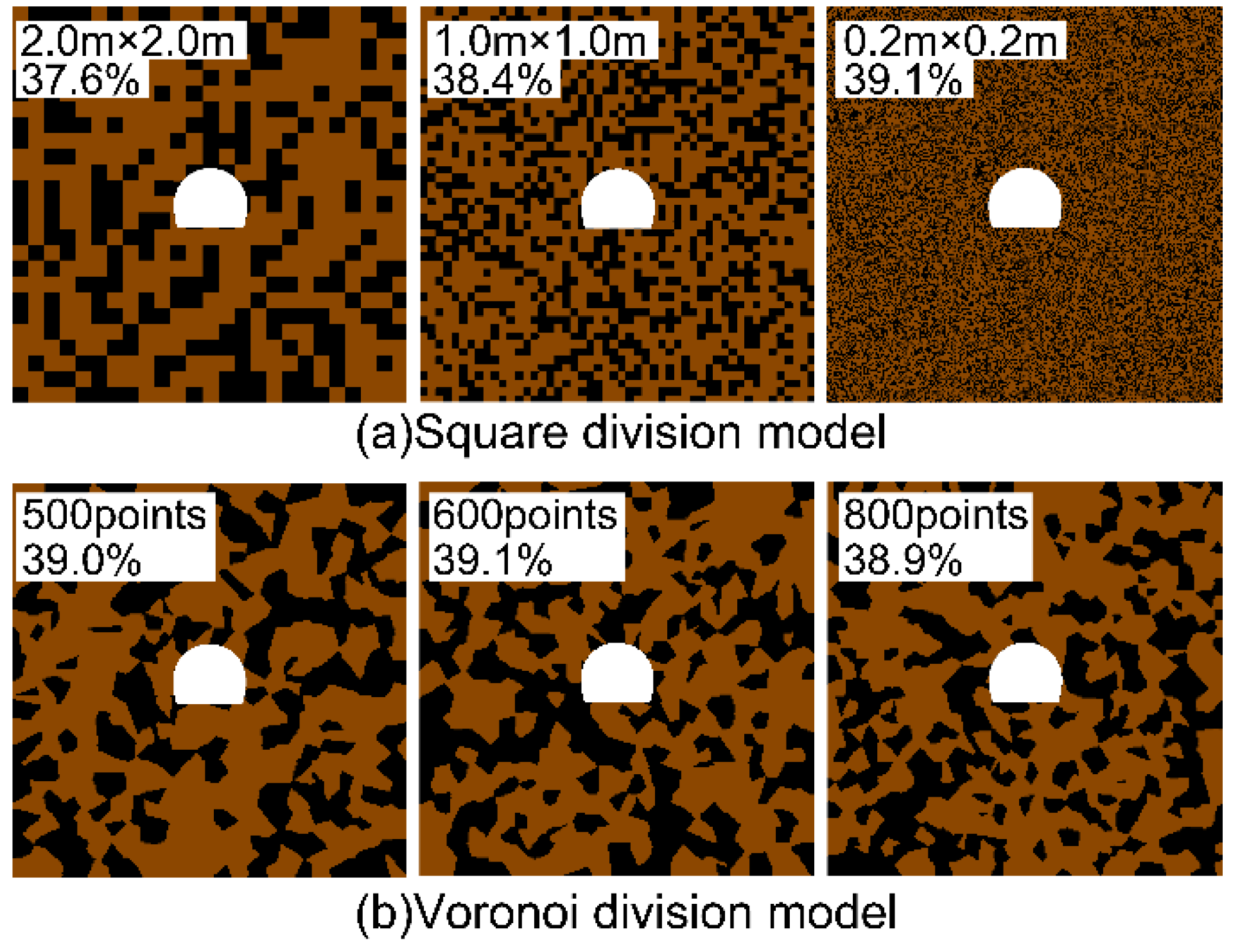
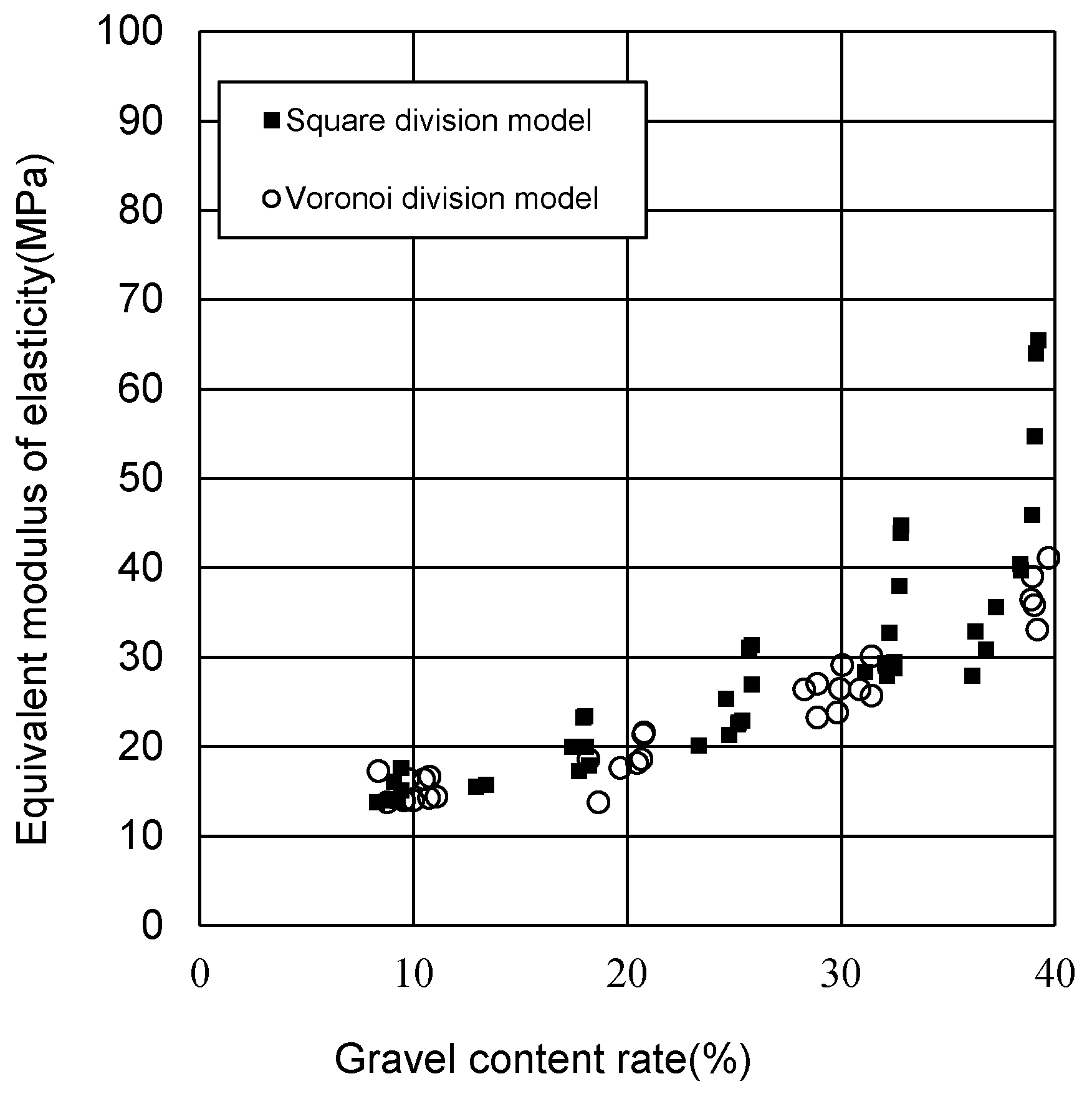
Figure 7 shows the equivalent elastic modulus in the difference between the two types of gravel modeling methods, the Voronoi division model, and the rectangular division model for investigating the magnitude of the effect of contact between gravel in a model with a gravel content of less than 40%. The relationship of gravel content is shown. Both the rectangular partition model and the Voronoi partition model shown in
Table 1 were divided into three types.
As is clear from
Figure 7, the equivalent elastic moduli of both the rectangular division model and the Voronoi division model increase as the gravel content increases, but when focusing on the variation in the equivalent elastic modulus for all gravel content of each model, it is rectangular. It can be seen that the split model is larger, and the tendency becomes more remarkable as the gravel content increases. It is also found that the rectangular division model had a larger variation of the equivalent elastic modulus at a gravel content of 40% or more. In Kobayashi’s experiment (Kobayashi [
18]) mentioned above, it was reported that this region exhibited a gravel content unaffected by the contact between gravel, but
Figure 3a shows a method for expressing gravel, such as the rectangular division model. There is a possibility that the deformation of the ground is restricted because the gravel has sharp corners.
Next, focusing only on the Voronoi partition model, in which the influence of contact between gravel is small under the ground condition where the gravel content is less than 40%, the relational expression between the gravel content and the equivalent elastic modulus is shown in
Figure 8. It is seen that at a high content rate of 60–70% or more, the equivalent elastic modulus for each gravel content rate varied, and it was reported that the gravel content was affected by the contact between gravel in the study by Kobiyashi [
18]. A tendency similar to that of the region was observed. From this, it was found that the Voronoi partition model is a suitable method for expressing the ground properties of the ground mixed with gravel before tunnel excavation. Therefore, the approximate curve obtained from the plot of the gravel content and the equivalent elastic modulus in the Voronoi partition model from
Figure 8 can be expressed by the following equation.
In the mixed ground of gravel and substrate with the strength listed in
Table 2, it is possible to estimate the equivalent elastic modulus of the ground from the gravel content.
5. Behavior Prediction during Tunnel Excavation
Here, a tunnel was excavated in the ground mixed with gravel, and the influences of the difference in the shape, size, and arrangement of the gravel on the tunnel and the ground around the tunnel is investigated. The ground model is a tunnel excavation analysis using two types of models, the rectangular partition model (1.0 m × 1.0 m) and the Voronoi partition model (Voronoi mother points = 600), already shown in
Section 3 (
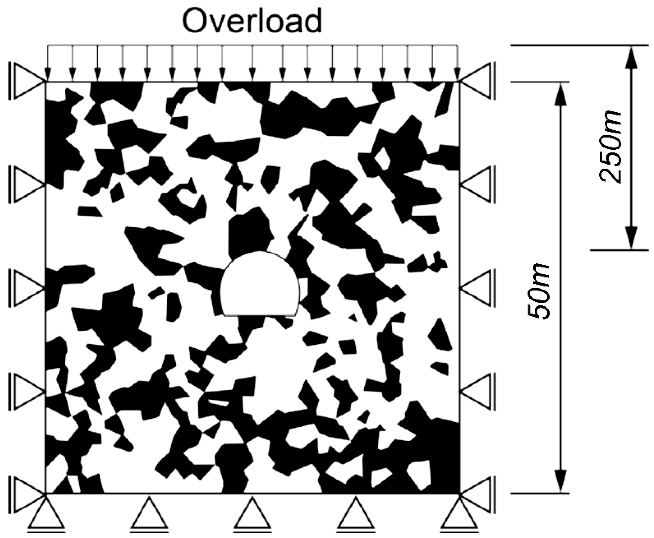
Table 1). We decided to perform the procedure. As for the load conditions shown in
Figure 9, after setting the initial load so that the soil cover of 250 m is on the top of the tunnel, the initial stress analysis and the diameter of 9.4 m and a height of 7.6 m were selected in the center of the area. A cross section corresponding to a two-lane road tunnel was excavated. It is assumed that the gravel extrusion phenomenon, which is one of the problems when excavating a tunnel in gravel-mixed ground, occurs when the maximum gravel size is sufficiently smaller than the tunnel size. As mentioned above, the maximum size of the gravel modeled in this study is 2 m for the rectangular partition model and 5 m for the Voronoi partition model.
First, based on the analytical results shown in
Section 3, (1) analytical results with a gravel content of 40% or less (see
Figure 10) showed no significant variation in the equivalent elastic moduli in both the rectangular division model and the Voronoi division model, (2) results with gravel content 40–60% with variations in the equivalent elastic modulus were seen only for the split model (see
Figure 11), and (3) an example of the analytical results of gravel content 60% or more with variations in the equivalent elastic modulus of both models is shown (see
Figure 12).
As shown in
Figure 10, the equivalent elastic modulus when the gravel content is 10% is calculated from Equation (1), and the physical property values are uniformly imparted to the analytical area of equivalent model and analysis considering gravel (
Figure 10). We compare the displacement contours of the rectangular division model (
Figure 10) and Voronoi division model (
Figure 10). As can be seen from this figure, in the equivalent model that does not consider gravel, the displacements around the tunnel and the upper part of the model are smaller overall compared to those of the model that considers gravel. In particular, the rectangular partition and the Voronoi partition models, which consider gravel, are unaffected by the contact between gravel or the difference in gravel shape, regardless of the difference in the simulation method. It can be seen that the large deformation of the sandy ground that accompanies this are found.
5.1. Ground Behavior When a Tunnel Is Excavated in a Ground with a Gravel Content of 40–60%
As can be seen from the gravel arrangement and tunnel ground displacement contour diagram, shown in
Figure 11 when the gravel content is 40–60%, the gravel shape is not considered. The equivalent model around the tunnel is considered rather than the model (
Figure 11). It can be seen that the displacement that occurs is smaller overall. From these results, it is considered that the ground with a gravel content of 40–60% corresponds to the transition region from the type that depends on the characteristics of the substrate to the one that depends on the skeleton structure of the gravel. It is considered that the rectangular division model (
Figure 11) and the Voronoi division model (
Figure 11) are starting to be affected by the contact between gravel. However, while the Voronoi division model extrudes the boulder at the top, which is not seen in the rectangular division model, the rectangular division model does not show this behavior. This is because, when gravel is expressed by rectangular elements, a collection of rod-shaped or uneven gravel is formed that is rarely seen in the ground where the actual tunnel is dug, and the tunnel displacement is constrained by their engagement. Therefore, it was found that the numerical analysis considering the gravel using the Voronoi division method is particularly effective under the ground conditions of such gravel content.
5.2. Ground Behavior When a Tunnel Is Excavated in a Ground with a Gravel Content of 60% or More
In the ground where the gravel content is further increased, as shown in
Figure 12, the displacement tendency of the rectangular partition model, the Voronoi partition model, and equivalent model does not change significantly. However, in the Voronoi partition model, the displacement that occurs in the region very close to the tunnel becomes large.
5.3. Summary of Ground Behavior When a Tunnel Is Excavated in a Ground Mixed with Gravel
From these results, when excavating a tunnel in a gravel-mixed ground, an equivalent numerical analysis model that inputs the homogeneous physical properties considering the gravel content can express the gravel extrusion and the accompanying large deformation of the sandy ground. However, from the numerical analysis results, it was found that the engineer may make an unsafe judgment. Since these ground behaviors are directly related not only to the workability of the tunnel but also to the safety of the builder, gravel smaller than the tunnel diameter is expected to appear on or near the tunnel face surface. Thus, it is preferable to perform numerical analysis simulating the substrate part. In addition, when performing numerical analysis considering gravel and substrate, the tendency of displacement to the tunnel periphery by the gravel modeling method does not differ significantly in the ground with a gravel content of 40% or less where there is little contact between gravel. Under a gravel content of 40% or more, where gravel is in contact with one another, the rectangular division model forms a collection of rod-shaped or uneven gravel that is rarely seen in the ground where the actual tunnel is dug. It can also be seen the Voronoi division model that reproduces the gravel shape is beneficial because the tunnel displacement is constrained by their engagement.
The analysis results thus far show an example for each gravel content rate; however, in many cases, the gravel arrangement of the Voronoi partition model considering the gravel shape and the equivalent physical property model not considering it are changed.
Figure 13 shows the difference in displacement that occurs in the tunnel when it is excavated in the created ground. Here, the equivalent physical property model is the result of plotting the analysis results when the Young’s modulus of the ground is 10 MPa to 800 MPa and the Poisson’s ratio is 0.3, and the Voronoi division model has a gravel content of 40%. Below that, gravel contents of 40–60% and 60% or more cases are colored. The crown subsidence shown on the vertical axis of the graph is the vertical displacement at the tunnel top contact, which is considered + (positive) in the downward direction. However, the side wall displacement is the average of the left- and right-side wall node displacements 1 m above S.L., and the sign is positive on the air side inside the tunnel. In tunnel standard specification (Japan Society of Civil Engineers, [
19]), the displacement measurements for tunnel excavation include measurements of internal space displacement, crown subsidence, and leg subsidence. Under the analytical conditions used in this study, no support was installed, and it was not necessary to consider the subsidence of the legs. Therefore, the nodal displacements corresponding to the inward displacement and crown subsidence of the tunnel were obtained.
From
Figure 13, it can be seen that in the case of the equivalent physical property model, the crown subsidence is directly proportional to the side-wall displacement. On the contrary, in the Voronoi partition model, there are cases where the crown subsidence and side-wall displacement are predominant, so there is a possibility that gravel may be missed in the equivalent elasticity model. Thus, it becomes difficult to predict.
Furthermore,
Figure 14 shows the analysis results of the Voronoi division model in relation to the gravel content rate and the maximum displacement. For the maximum displacement of the tunnel here, the maximum value of the displacement that occurs in the tunnel wall surface element is plotted.
From
Figure 14, it was found that the maximum displacement of the tunnel tended to decrease as the gravel content increased. However, there are variations in the maximum displacement with respect to the gravel content. Therefore, it is difficult to measure the gravel content of the ground where the tunnel will be excavated and predict the amount of displacement that will occur in the tunnel from
Figure 14. For gravel-mixed ground, it is important to measure and predict the arrangement of gravels and to simulate them using the Voronoi division model.
6. Conclusions
In this study, we simulated the physical properties and regions of gravel and substrate to propose a numerical analysis model that considers the gravel dropout and the accompanying large deformation of sandy gravel, which are problems in tunnel construction in gravel-mixed ground. We evaluated the numerical analysis results. In particular, we considered the ground as a linear elastic body and proposed a simple ground behavior prediction method, which can be useful in practical tunnel design and construction. As a result, the following conclusions were found:
(1) For simulating each of the gravel and substrate of the ground mixed with gravel by continuity analysis, the gravel shape that appears in the actual field is randomized or irregular using the Voronoi partitioning model, which also uses the voxel method. It was found that it can be generated.
(2) Focusing on the deformation characteristics of the gravel-mixed ground, it was found that the Voronoi partitioning model in this study is less likely to be affected by contact between gravel and is an effective creation method of the numerical analysis model for the gravel-mixed ground. In addition, the relational expression between the gravel content and the equivalent elastic modulus could be derived.
(3) Furthermore, when excavating a tunnel in a gravel-mixed ground, the equivalent model in which the equivalent physical properties are uniformly input without considering the shape and dimensions of the gravel can be used to extrude the gravel generated around the tunnel at any gravel content rate. A high possibility that the large deformation of the accompanying sandy ground cannot be evaluated was seen. Of the analysis methods that consider the shape and size of the gravel, the Voronoi division model extrudes the gravel in terms of the content of gravel with a gravel size of about 0.5D or less exceeding 40% gravel content. A large deformation of the sandy ground could be expressed. From this, it was found that performing numerical analysis simulating the gravel and the substrate part is preferable when gravel appears on or near the tunnel face surface.


