Article

Morphological Observation of LiCl Deliquescence in PDMS-Based Composite Foams

by
Emanuela Mastronardo
1,*,
Elpida Piperopoulos
1,2,
Davide Palamara
1,
Andrea Frazzica
2 and
Luigi Calabrese
1,2,*
1
Engineering Department, University of Messina, 98166 Messina, Italy
2
CNR ITAE, 98126 Messina, Italy
*
Authors to whom correspondence should be addressed.
Appl. Sci. 2022, 12(3), 1510; https://doi.org/10.3390/app12031510
Submission received: 21 December 2021 / Revised: 20 January 2022 / Accepted: 28 January 2022 / Published: 30 January 2022

Abstract

:
The LiCl-based heat storage system exhibits a high-energy density, making it an attractive and one of the most investigated candidates for low-temperature heat storage applications. Nevertheless, lithium chloride, due to its hygroscopic nature, incurs the phenomenon of deliquescence, which causes some operational challenges, such as agglomeration, corrosion, and swelling problems during hydration/dehydration cycles. Here, we propose a composite material based on silicone vapor-permeable foam filled with the salt hydrate, hereafter named LiCl-PDMS, aiming at confining the salt in a matrix to prevent deliquescence-related issues but without inhibiting the vapour flow. In particular, the structural and morphological modification during hydration/dehydration cycles is investigated on the composite foam, which is prepared with a salt content of 40 wt.%. A characterization protocol coupling temperature scanned X-ray diffraction (XRD) and environmental scanning electron microscopy (ESEM) analysis is established. The operando conditions of the dehydration/hydration cycle were reproduced while structural and morphological characterizations were performed, allowing for the evaluation of the interaction between the salt and the water vapor environment in the confined silicon matrix. The material energy density was also measured with a customized coupled thermogravimetric/differential scanning calorimetric analysis (TG/DSC). The results show an effective embedding of the material, which limits the salt solution release when overhydrated. Additionally, the flexibility of the matrix allows for the volume shrinkage/expansion of the salt caused by the cyclic dehydration/hydration reactions without any damages to the foam structure. The LiCl-PDMS foam has an energy density of 1854 kJ/kg or 323 kWh/m3, thus making it a competitive candidate among other LiCl salt hydrate composites.

1. Introduction

The energy transition is a necessary path toward the transformation of the worldwide energy sector from fossil-based to zero carbon by 2050, which is fundamental to reduce energy-related CO2 emissions to limit climate change [1]. One of the main pillars for the energy transition is the global spread of the use of solar energy, being basically endless and free [2]. However, its diurnal nature, weather conditions, and seasonality might make solar energy unavailable when required. This time lag between energy supply and demand is a critical point to be addressed for renewable solar energy development and replacement of fossil-based energy. For this aim, thermal energy storage (TES) is an efficient and effective means to store solar energy when in excess, thus shifting the peak load demand into off-peak hours.
Among TES technologies, the thermochemical one exploits materials with a large reaction enthalpy and reversibility. Inorganic salt hydrate (MnAm∙XH2O) is a widely used class and one of the most promising investigated classes of materials for thermochemical heat storage [3,4], which is based on the following storage reaction:
MnAm∙nH2O + heat ↔ MnAm∙(n − x)H2O + xH2O
Heat is transferred from a selected source to the material and the dehydration reaction takes place (storage step). The heat is stored for as long as the salt is in the dehydrated form. When heat is required, water is made accessible to the salt, the reversible hydration takes place, and heat is released (release step). One of the main advantages of this technology is, indeed, the possibility to control the heat release by controlling the water vapor accessibility to the dehydrated salt, thus making the heat discharge available and controllable on-demand [5].
Due to this great potential, several pure salt hydrates and composite systems with different salts were investigated: e.g., LiBr [6], MgSO4 [7], CaCl2 [8], SrCl2 [9], and LiCl [10]. Among them, LiCl is one of the salts that raised more interest for low/medium temperature (i.e., below 120 °C) TES application [11]. Indeed, the high-energy density of the LiCl-based system makes it an attractive candidate from the heat storage capacity cost perspective, thus resulting in one of the materials with a lower cost per kWh stored (~6 €/kWh) [12]. Nevertheless, lithium chloride is one of the most hygroscopic salts known and it incurs the phenomenon of deliquescence.
Deliquescence is a first-order phase transformation of the solid to a saturated solution, which occurs at a specific relative humidity (RH) inherent to the properties of the solid and the temperature [13]. When this RH is reached, the aqueous solution is the thermodynamically favored phase and dissolution begins, whereby liquid patterns or patches of solution form on the surface. As the humidity further increases, these patches merge and form a thin liquid film, which gradually thickens; the entire solid particle dissolves and transforms into a solution drop; and its radius abruptly grows. In a closed environment, a saturated solution of lithium chloride will form an equilibrium at a relative humidity of about 12.4% (20 °C). The reverse process to deliquescence is called efflorescence. Efflorescence is the process of the crystallization and expulsion of water from the crystallized material when the decreasing humidity reaches another threshold value, called efflorescence relative humidity (ERH).
Several issues arise due to the deliquescence phenomenon in TES technologies. The liquid film that forms on the surface of the salt crystal inhibits the rehydration reaction (e.g., in the case of the LiCl, LiBr, and CaCl2) [14,15]. In addition, the sorbate mass transfer into the system will be hindered, causing issues such as high-pressure drops and ultimately system failure, but also corrosion issues arise due to the dripping of the salt solution to other metal components of the systems.
Accordingly, several efforts were carried out to implement LiCl-based TES technologies and, more specifically, from the material perspective. The general idea is to embed the salt into porous matrices (such as carbon foams, expanded natural graphite, zeolite, vermiculite, silica gel, etc.) to prevent deliquescence and improve water transport into the materials [8,16,17].
Zhang et al. developed a LiCl-based composite on mesoporous alumina [18]. The material showed a TES density of up to 1040 J/g. However, due to the low pore volume of the alumina, only ~15 wt.% of the salt could be loaded in the matrix, thus limiting the possibility of further increasing TES density. Multi-walled carbon nanotubes (MWCNTs), due to their extremely large and variable pore volume, were used as a matrix to host LiCl salt [19]. This composite, with a 44 wt.% content of LiCl salt, achieved a heat storage capacity of 1.6–1.7 kJ/g. More recently, a LiCl/vermiculite, with ~59 wt.% of LiCl, was developed by Grekova and coworkers [20]. The heat storage capacity of this composite is 1.8–2.6 kJ/g (224–253 Wh/m3). It has to be pointed out that, intrinsically, the porous structure of natural mineral vermiculite is non-reproducible and so is the composite. Additionally, vermiculite suffers from hydrothermal structural stability issues that are critical for the technology’s long-term durability. Yu et al. developed silica gel-LiCl composites by varying the amount of embedded salt between 10 and 40 wt.% [21]. An optimum compromise between the heat storage capacity and material stability was identified in the composition with 30 wt.% of embedded salt. For this composition, a heat storage capacity of 480 J/g was determined. The presence of salt deposited onto the external surface of the composite has clearly a detrimental effect. This issue was addressed specifically on mesoporous silica gel-LiCl composites with a post-treatment based on an adsorption phase followed by a slow desorption phase, which allowed the salt to move from the surface into the pores, likely due to a capillary effect [22].
The investigated matrices, being rigid structures, could limit the mechanical stability of the material over cycling due to the consecutive expansion and contraction of the salt grains during the hydration and dehydration steps. In this regard, the use of flexible polymeric macro-porous foam as matrices for salts was proposed in literature for other types of salts, e.g., MgSO4·7H2O [23,24]. The flexibility of these foams can accommodate the expansion and shrinkage of the salt hydrate volume during the hydration and dehydration reactions, thus enhancing the mechanical stability of the composite over the cycles. In addition, the foam should embed the salt, thus retaining the deliquescence that inevitably occurs due to the operating conditions.
In situ studies on TES materials can certainly provide an in-depth understanding of the reaction mechanism and materials changes during the charging/discharging operations, thus leading to valuable information for the advancement of TES materials. Here, we investigate the structural and morphological modification during hydration/dehydration cycles on a LiCl-silicon foam (LiCl-PDMS) with a salt content of 40 wt.%. Specifically, a characterization protocol coupling temperature scanned X-ray diffraction (XRD) and environmental scanning electron microscopy (ESEM) analysis was proposed. The operando conditions of the dehydration/hydration cycle were reproduced while structural and morphological characterizations were performed, allowing for the evaluation of the interaction between the salt and the water vapor environment in the confined silicon matrix.

2. Materials and Methods

2.1. LiCl-PDMS Foam Synthesis and Characterization

For this study, a silicone foam based on a poly(methylhydrosiloxane) (PMHS) and silanol-terminated polydimethylsiloxane (PDMS) mixture, filled with 40 wt.%. of the LiCl salt final weight, was used. The macro-porous composite foam was prepared by a dehydrogenative coupling reaction between hydroxyl functional materials and hydride functional siloxanes in the presence of a metal salt catalyst (bubbling agent), inducing the hydrogen evolution according to the procedure reported by Calabrese et al. [25]. Briefly, the PDMS and PMHS monomers (supplied by Gelest Inc., Morrisville, PA, USA) used as a monomer and hardener, respectively, were mixed together (PDMS:PMHS = 2:1). Then, LiCl·H2O salt (>99.9%, Sigma Aldrich, St. Louis, MO, USA) was added under vigorous mixing until a homogenously and well-dispersed slurry was obtained. Anhydrous denatured ethanol (Sigma Aldrich, St. Louis, MO, USA) was added (~8 wt.%) to better mix and homogenize the slurry. A tin salt catalyst (bis(2-ethylhexanoate)tin, Gelest Inc., Morrisville, PA, USA) was added (~8 wt.%) in order to activate the reaction. Finally, the foaming process was carried out by placing the slurry in a cylindrical mold at 60 °C for 24 h and the dehydrogenative coupling reaction between the slurry constituents took place. Specifically, the hydroxyl and hydride functional groups in PDMS and PMHS, respectively, reacted, forming a siloxane link, namely Si-O-Si, that gradually led to a tri-dimensional rubber-like silicone network. Hydrogen is also a reaction by-product that acts as a foaming agent.
The homogeneity and void distribution of the LiCl-PDMS foam were analyzed on the material cross-sectional area at 50× magnification by using a 3D optical digital microscope, specifically HK-8700 (Hirox, Tokyo, Japan).

2.2. Hydration/Dehydration Cycle through Thermogravimetric Dynamic Vapor Sorption System

A complete hydration/dehydration cycle in a controlled (temperature, RH) and measurable (mass change) environment was performed through a thermogravimetric dynamic vapor sorption system (DVS Vacuum Surface Measurement Systems). The system consists of a micro-balance (precision of ±0.1 μg) and a water vapor pressure flow controller placed in the measuring chamber. Before the test, the sample was dehydrated at 150 °C under vacuum for 2 h. The hydration/dehydration cycle was performed in isothermal mode at 30 °C and varying the RH from 0 to 90%.

2.3. In-Situ Characterization of LiCl-PDMS Foam

In situ X-ray diffraction (XRD, D8 Advance Bruker diffractometer Bragg-Brentano theta-2theta configuration, Cu Kα, 40 V, 40 mA) was carried out on the LiCl-PDMS foam while dehydrating. The diffractometer was equipped with a heating chamber (HTK 1200N, Anton Paar) that enabled the material dehydration reaction from r.T. up to 80 °C under a nitrogen flow. A heating/cooling rate of 10°C/min was used. Each scan was acquired in the 2θ range of 10–80°, with a step size of 0.010° in 0.1 s, immediately after reaching the target temperature and after 30 min of holding time to allow for material equilibration. After the heating step (dehydration), the material was cooled to r.T. under nitrogen flow and XRD patterns were collected immediately after reaching the set temperature as well as after 30 min of holding time. Additionally, after cooling, the material was left for 1 h under atmospheric conditions to rehydrate and XRD was collected. Lattice parameters and the phase fraction of hydrate and anhydrous LiCl salt were evaluated by Rietveld refinement using the GSAS-II Crystallography Data Analysis Software [26].
Morphological observation of LiCl-PDMS foam while hydrating was carried out by an environmental scanning electron microscope (ESEM, FEI Quanta 450) operating with an accelerating voltage of 8 kV. Initially, the material was dehydrated in oven at 80 °C for 12 h and then placed in the ESM chamber for acquiring the micrographs under controlled water vapor atmosphere. The relative humidity (RH) was varied between 0 and 90% by tuning the temperature and water vapor pressure in the ranges of 5–40 °C and 10–800 Pa. Specifically, the micrographs were acquired after an equilibration time of 30 min under isothermal conditions (40 °C), varying the water vapor pressure from 10 Pa to 800 Pa (0.1–10.9% of relative humidity), and then under isobaric conditions (800 Pa), varying the chamber temperature from 40 °C to 5 °C (10.9–91.3% of relative humidity). The analysis was concluded, restoring the initial conditions. For clarity, a scheme of the ESEM analysis cycle conditions is shown in Figure 1.

2.4. Hydration Heat Capacity Measurement

The hydration enthalpy, namely the heat release capacity, was evaluated through a modified coupled TG/DSC apparatus (Setaram LabsysEvo) that enables measurements under saturated vapour working conditions, as described elsewhere in literature [27,28]. Briefly, the system was equipped with a glass evaporator whose temperature was controlled by an external thermo-cryostat. The entire system was placed in a thermostatic box that allows for preventing condensation on the internal surfaces of the circuit or in the measuring chamber, and the chamber and evaporator pressures were continuously monitored. According to the testing procedure, ~16 mg of the material was placed into the measuring chamber of the TG/DSC apparatus and degassed at 150 °C for 12 h under vacuum (~10–3 mbar) to completely dehydrate the sample. Subsequently, the sample temperature was cooled down to the initial adsorption temperature (80 °C) and water vapor (vapor pressure of 12 mbar) was streamed in the measuring chamber. The sample temperature was decreased to the final discharging temperature of 35 °C, corresponding to an RH of ~22%, after which it was isothermally held for 140 min. This results in a sample mass gain due to the water uptake. Hence, the heat involved in the hydration reaction can be estimated from the integration of the DSC signal.

3. Results

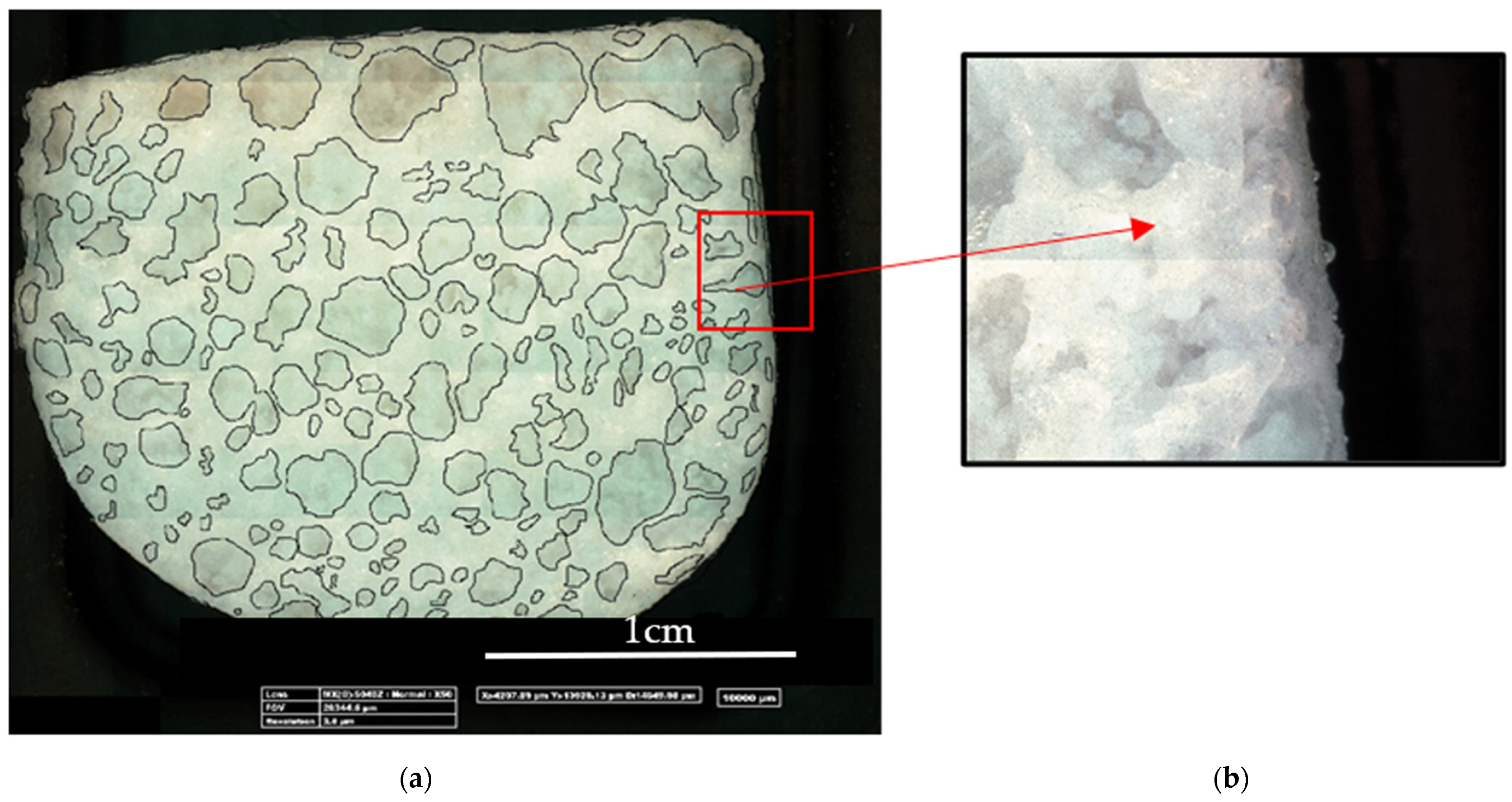
3.1. LiCl-PDMS Foam Optical Analysis

The as-synthesized LiCl-PDMS foam has a measured apparent density (ρfoam) and solid density (ρsolid) of 0.628 and 1.094 g/cm3, respectively, and thus a porosity of 42%, calculated as:
P ( % ) = 1 ρ foam ρ solid · 100
The apparent density was calculated as the sample weight to volume ratio, while the solid density was calculated, applying the mixture rule, by using the constituent content in the composite foam. A 3D optical image of the cross-sectional area of the LiCl-PDMS foam at 50× magnification is shown in Figure 2. The foam exhibited both open and closed porosities caused by the foaming process occurring during the synthesis. The porosities’ size broadly varied from 1 to 50 mm and it can be argued that the larger porosities were likely formed due to the coalescence of several bubbles. The LiCl salt appeared to be distributed on the surface of the open porosities but was also embedded by the matrix. The optical analysis was carried out under environmental conditions and this allowed the salt to absorb the humidity present in the atmosphere and hydrate. From the inset of Figure 2, some drops are clearly visible on the surface of the foam, likely due to the deliquescence phenomenon. Indeed, the open porosities present on the surface of the foam allow for the exposure of LiCl to the humidity, thus causing the deliquescence phenomenon.

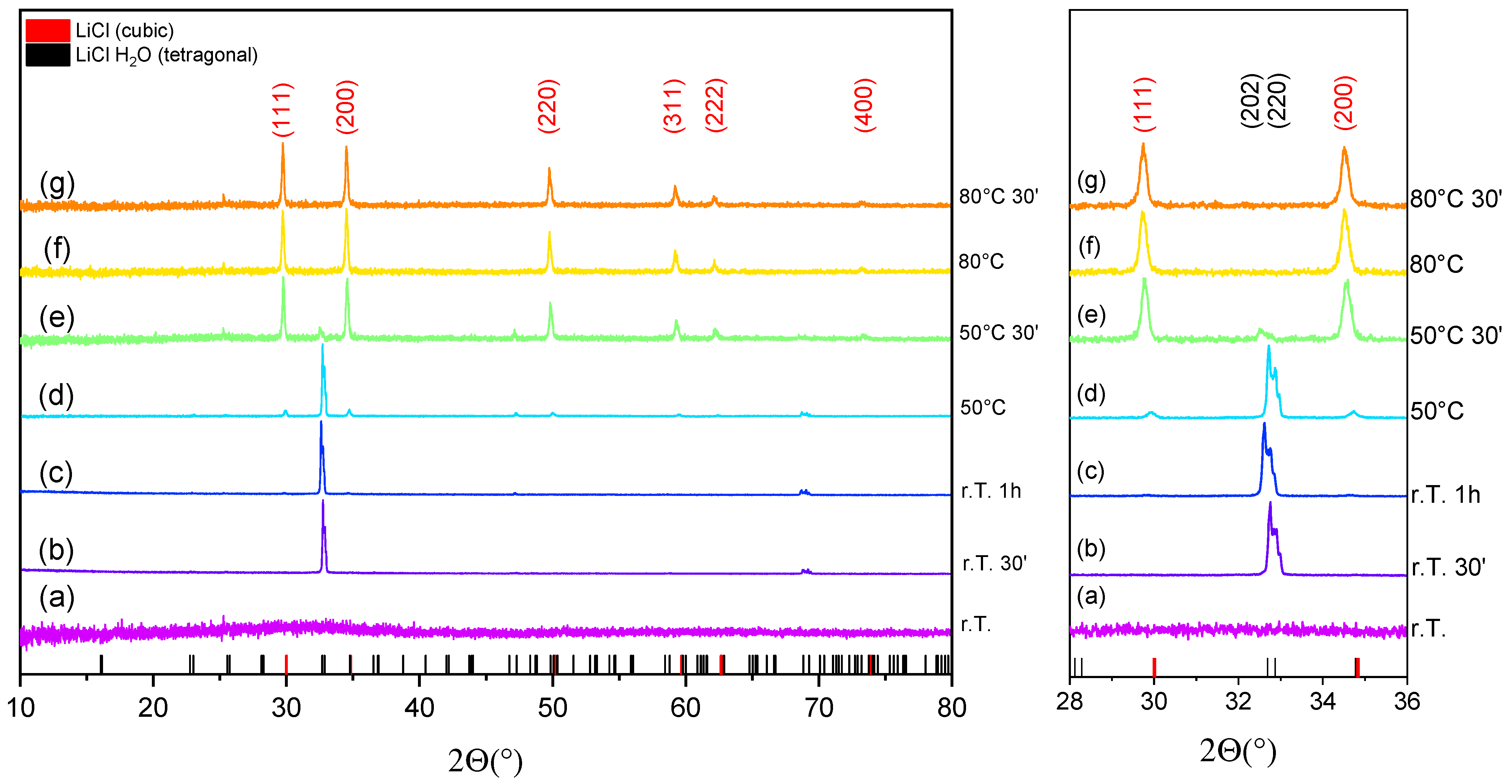
3.2. In-Situ X-ray Diffraction of LiCl-PDMS Foam during Dehydration Reaction

We report, in Figure 3, the crystal structure evolution of LiCl-PDMS foam while dehydrating through in situ XRD measurements. The XRD patterns code, the experimental conditions, the refined lattice parameters, and the volume and phase fraction are reported in Table 1.
It is well known from literature that LiCl, besides anhydrous, exists in another four solid hydrate forms with one, two, three, and five water molecules, and that these salts are extremely hygroscopic and soluble in water. As inferred from XRD analysis in Figure 2 (pattern (a)), at the initial conditions, namely r.T. and when exposed to air, the LiCl in the PDMS foam is completely amorphous (Figure 3 (pattern [a])), thus indicating that the salt is overhydrated.
After 30 min under a dry N2 flow, lithium chloride was monohydrated (PDF 04-013-8884) and exhibited a tetragonal structure (P42/nmc; Figure 3 (pattern [b])). After 1 h under the same conditions, the material began to dehydrate (Figure 3 (pattern [c])) and the cubic (Fm-3m) anhydrous phase (PDF 00-004-0664) was present in ~3.7% of the material fraction, as calculated from the Rietveld refinement. As the temperature increased to 50 °C, the most intense reflections indicative of the cubic structure (indexed (111) and (200)) began to be more clearly distinguishable (Figure 3 (pattern [d])), while the ones indicative of the tetragonal structure (indexed (202) and (220)) significantly decreased in intensity. From the phase fraction evolution in Table 1, it is clear that most of the dehydration reaction occurs during the isothermal holding step at 50 °C (Figure 3 (pattern [e])). Indeed, after reaching this temperature, the fraction of the anhydrous phase increased by about 60%. At 80 °C, the material was fully dehydrated (Figure 3 (pattern [f])), and a slight increase in the lattice parameters was observed after the isothermal hold at 80 °C for 30 min (Figure 3 (pattern [g]), Table 1). As lithium chloride transformed from monohydrate to anhydrous, it underwent a significant volume contraction, reduced by ~70% of its initial volume.
After the complete dehydration reaction, the temperature in the XRD chamber was decreased to r.T. and the collected XRD pattern is reported in Figure 4. The analysis after cooling at r.T. (Figure 4, patterns (h) and (i)) showed the persistence of the anhydrous phase obviously due to the lack of humidity in the chamber. In order to rehydrate the material, the LiCl-PDMS foam was exposed to air at r.T. for 1 h. The collected XRD pattern (Figure 4, pattern (j)) showed a completely amorphous structure due to the overhydration of the LiCl salt. This, as expected, is indicative of the complete reaction reversibility.

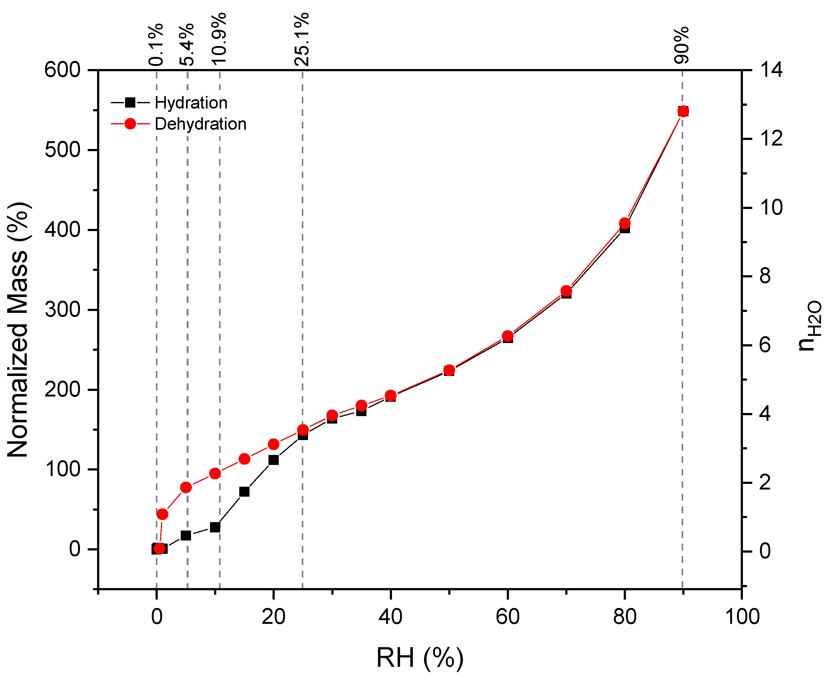
3.3. Hydration/Dehydration Thermochemical Behavior

The LiCl-PDMS foam thermochemical behavior during a dehydration/hydration cycle was characterized through a thermogravimetric dynamic vapor system under isothermal conditions at 30 °C by varying the chamber RH in the range of 0–90% and the results are shown in Figure 5. The mass change was normalized to the salt hydrate content (40%) in the foam.
While increasing the RH in the chamber, the hydration conditions became more favorable for the reaction to proceed and the mass uptake progressively increased. More specifically, the material exhibited a small water uptake at low partial pressure (below 1% RH). At intermediate RH values, between 5 and 25%, a quasi-linear water uptake from ~17 to ~143 wt.% was observed. Finally, above an RH of 25%, a notable mass uptake from ~143 up to 550 wt.% was observed. Taking into account the hydration reaction of LiCl salt, which is
LiCl ( s ) + H 2 O ( g )     LiCl · H 2 O ( s )
and the molecular mass of both reagents and products (MLiCl = 42.39 g/mol, MLiCl·H2O = 60.41 g/mol), a theoretical mass uptake of 42.39% is expected when LiCl converts into its monohydrated phase. Hence, it is evident from the gravimetric profile that the full conversion of LiCl into its monohydrated phase occurs at an RH of between 10 and 15%. Above this value, the material is overhydrated and it reaches up to ~13 water molecules. The dehydrated LiCl can exist in the solid form at a low temperature below 20 °C. Hence, the water intake over the monohydrated threshold at the experimental temperature of 30 °C could be caused by the capillary condensation mechanism and the deliquescence phenomenon is expected to take place.
A hysteresis was observable between the dehydration and hydration reactions in the RH range of 0–25%, while above this RH value, the hydration and dehydration profiles almost perfectly overlapped. In general, the presence of hysteresis between the sorption and desorption isotherms indicates that the water diffusion through the material structure is slower as the lattice re-arranges upon hydration [29]. This can be applied to LiCl salt, indeed, as previously observed from in situ XRD analysis (Figure 3 and Figure 4), wherein the material transformed from a completely amorphous structure to a more ordered one when it converts progressively from the (over)hydrated to the mono as well as dehydrated phase.
In Figure 5, we report the RH values adopted for the ESEM conditions that will be discussed in the following Section 3.3.

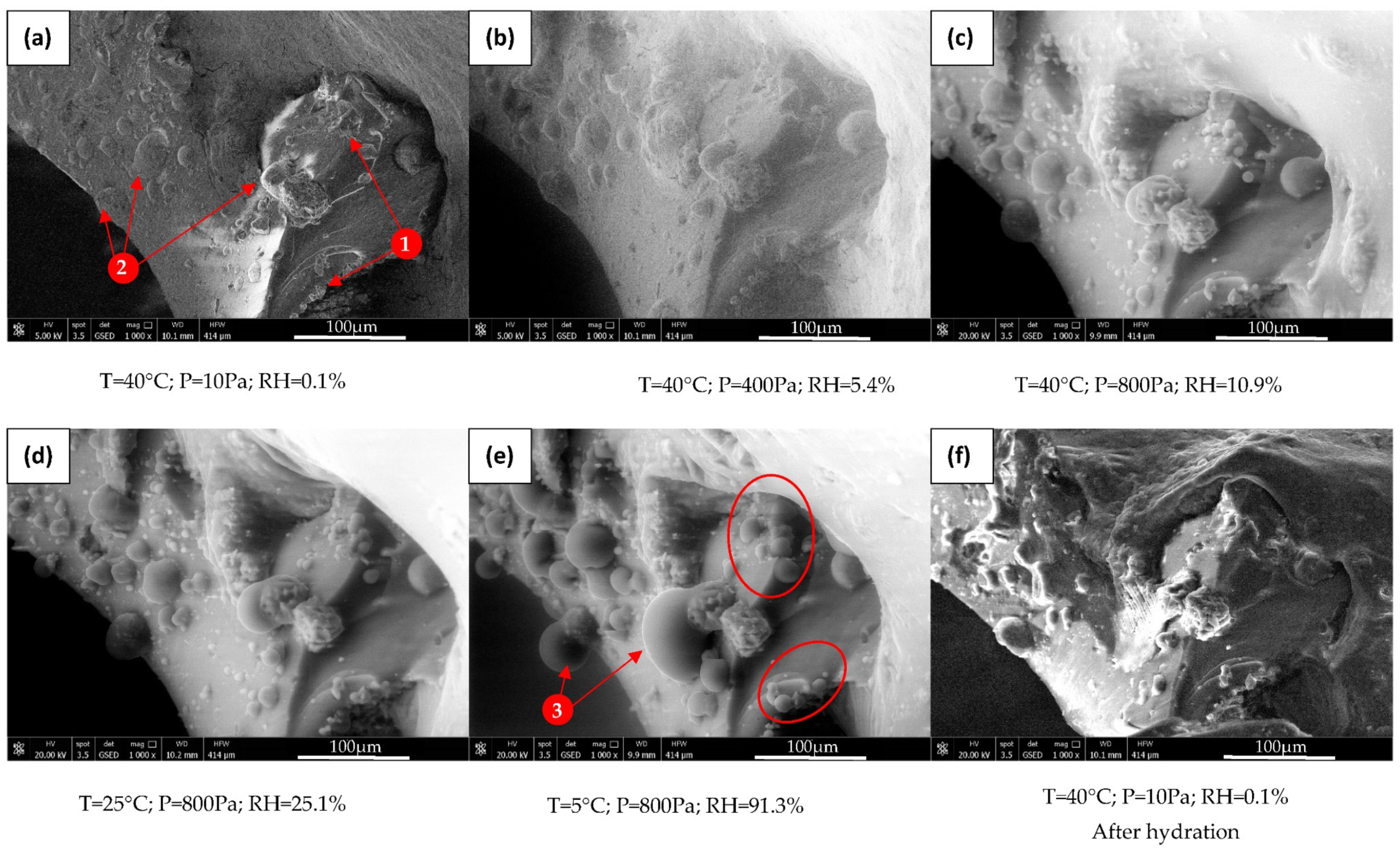
3.4. Morphological Characterization of LiCl-PDMS Foam during Hydration Reaction

An environmental SEM analysis was conducted on the LiCl-PDMS foam simulating the hydration/dehydration reaction conditions. This approach allowed for visually evaluating the morphological modification while hydrating and dehydrating the LiCl salt embedded in the porous silicon matrix. The dehydration and hydration conditions were obtained with varying temperature and water vapor pressure in the ranges of 5–40 °C and 10–800 Pa, respectively, in order to vary the chamber RH at which the material was exposed.
Initially, the material was fully dehydrated and the RH during the analysis was increased from 0.1% to 91.3% in order to favor the hydration reaction. Afterwards, the RH was decreased to 0.1% to favor the LiCl salt dehydration reaction. Hence, the experiment reproduced the operating conditions of a whole hydration/dehydration cycle. In Figure 6, we report the micrographs at the selected pressure and temperature conditions in the climatic chamber of the microscope. The area selected for the analysis is an inner part of the foam and is indicative of the overall morphology.
At an RH of 0.1%, according to the DVS analysis, the LiCl salt in the PDMS foam should be in its anhydrous phase, and from SEM micrographs on the foam surface, some asperities (1) and bubbles (2) are visible (Figure 6a). It is likely that the asperities consist of loose salt agglomerates, while the bubbles, with a smooth surface and different sizes, might embed the salt in the foam matrix, thus functioning as a covering layer.
By increasing the RH to 5.4%, no visible morphological modifications could be detected (Figure 6b). Nevertheless, at such an RH value, the beginning of the hydration was expected from the hydration profile, with a water mass uptake of ~17 wt.%. As the RH increased to 10.9%, the hydration reaction was more promoted and the bubbles began to swell (Figure 6c), and their volume increased as the RH increased clearly due to the progressive acquisition of more water molecules (Figure 6d,e), in agreement with the DVS analysis.
At an RH of 25.1%, the conversion of LiCl into its monohydrate phase was complete (Figure 5), and above this RH value, the deliquescence phenomenon was expected to occur. The bubbles doubled and tripled their volume at an RH of 91.3% (as indicated by point 3 in Figure 6e). The asperities (red circles in Figure 6e) increased their volume as well as the RH increased, assuming a roundish shape typical of a drop, thus likely indicative of the deliquescence phenomenon. No detachment of the salt from the foam was observable because of the volume expansion. Nevertheless, the loose salt (asperities) appeared to be slightly agglomerated. Additionally, no damages were evident on the PDMS foam where the salt was embedded (bubbles), thus indicating the ability of the material to easily expand and contract as a consequence of the hydration/dehydration cycles and to both effectively protect and retain the embedded salt hydrate.
As final step of the ESEM analysis, the environmental chamber conditions were restored to the initial ones, that is, an RH of 0.1%. Under these conditions, the dehydration reaction was induced and the hydration/dehydration cycle was completed. It could be clearly observed that the material morphology was almost unmodified, that is, no damages due to the retained water and volume expansion/contraction were present, thus preserving the reusability of the foam. The presence of incomplete dehydrated salts cannot be exclued. Remarkably, no defects or cracks were detected, confirming the effectiveness of this approach for obtaining a durable, flexible, and porous-sorbents composite.

3.5. Energy Storage/Release Density

To estimate the foam energy storage/release density, the heat release while hydrating was measured with a coupled TG/DSC analysis under pure water vapor atmosphere to simulate the typical operation of a TES system working with a closed cycle. The TG/DSC profile of LiCl-PDMS foam under the temperature drop of 80–35 °C at 12 mbar of water vapor pressure (10 °C of evaporation temperature) is shown in Figure 7a. The material began to uptake water at ~60 °C, reaching a plateau at 35 °C, that is, under 12 mbar of water vapor pressure, it corresponded to an RH of ~22%. Under this condition, the total percentage of the normalized mass gain was ~170%, corresponding to ~4 water molecules, which is in good agreement with the DVS analysis (see Figure 5). Hence, the material was overhydrated. From the integration of the heat flow profile, the LiCl-PDMS foam energy density associated with this water uptake was estimated to be ~1854 kJ/kgfoam (or ~323 kWh/m3). From the deconvolution of the heat flow signal, as shown in Figure 7b, it is evident that four thermal events (exothermic) occurred while the material hydrated. The mass uptake related to the first peak (~40%) is very close to the one occurring when LiCl converted into its monohydrated phase (42.39%), while the second one began at a temperature of 45 °C, that is, under 12 mbar of water vapor pressure, it corresponded to an RH of 12.5%, very close to the value at which a saturated solution of lithium chloride will form an equilibrium (12.4%). Similarly to the DVS analysis, the remaining two peaks could be associated with the water intake over the monohydrated threshold, which can likely be caused by the capillary condensation mechanism in the foam.

4. Final Remarks

From the morphological analysis, no defects or cracks were detected, confirming the effectiveness of this approach for obtaining a durable, flexible, and porous-sorbents composite. Nevertheless, it has to be pointed out that LiCl is not completely embedded by the PDMS foam but, rather, it is partially deposited on the external foam surface. Critically, this superficial salt could affect the overall TES performances due to possible corrosion processes. Hence, this issue should be addressed. Additionally, the material stability at long aging cycles is a key point for thermochemical energy storage applications and will be addressed in the following studies.
With respect to some of the most recently investigated LiCl-based composites (see Table 2), the LiCl-PDMS foam exhibits larger heat storage/release capacity and energy density under both similar testing conditions and similar LiCl content. Hence, it can be considered a competitive candidate among other LiCl salt hydrate composites.

5. Conclusions

Here, we investigated a composite material based on silicone vapor-permeable foam filled with 40 wt.% of LiCl (LiCl-PDMS), aiming at confining the salt in a matrix to prevent deliquescence-related issues but without inhibiting the vapour flow. Specifically, we studied the structural and morphological modification of the composite foam during the hydration/dehydration cycles through in situ XRD and ESEM analysis. In situ XRD enabled the material dehydration reaction from room temperature up to 80 °C, while the environmental SEM analysis simulated the hydration/dehydration reaction conditions, thus allowing for the evaluation of the interaction between the salt and the water vapor environment in the confined silicon matrix. The results show an effective embedding of the material, which limits the salt solution release when overhydrated. Additionally, the flexibility of the matrix allows for the volume shrinkage/expansion of the salt caused by the cyclic dehydration/hydration reactions without any damages to the foam structure. Indeed, as lithium chloride transformed from monohydrate to anhydrous, a significant volume contraction was observable (~70% of its initial volume). The LiCl-PDMS foam energy density was measured with a customized coupled thermogravimetric/differential scanning calorimetric analysis (TG/DSC) during the hydration phase and the estimated energy density value was ~1854 kJ/kg (or ~323 kWh/m3), thus making it a competitive candidate among other LiCl salt hydrate composites.

Author Contributions

Conceptualization, L.C. and E.P.; investigation, E.P., A.F., D.P. and E.M.; data curation, E.M. and D.P.; validation, L.C., E.P., A.F. and E.M.; writing—original draft preparation, E.M.; writing—review and editing, E.M., E.P. and L.C. All authors have read and agreed to the published version of the manuscript.

Funding

This research study was funded by the Italian Ministry of University and Research (MUR), program PON R&I 2014/2020—Avviso n. 1735 del 13 July 2017—PNR 2015/2020, under project “NAUSICA—NAvi efficienti tramite l’Utilizzo di Soluzioni tecnologiche Innovative e low CArbon”, CUP: B45F21000680005.

Conflicts of Interest

The authors declare no conflict of interest. The funders had no role in the design of the study; in the collection, analyses, or interpretation of data; in the writing of the manuscript, or in the decision to publish the results.

References

  1. Gielen, D.; Boshell, F.; Saygin, D.; Bazilian, M.D.; Wagner, N.; Gorini, R. The role of renewable energy in the global energy transformation. Energy Strategy Rev. 2019, 24, 38–50. [Google Scholar] [CrossRef]
  2. IRENA. Global Energy Transformation: A roadmap to 2050, International Renewable Energy Agency; IRENA: Abu Dhabi, United Arab Emirates, 2018; p. 12. [Google Scholar]
  3. Liu, H.; Wang, W.; Zhang, Y. Performance gap between thermochemical energy storage systems based on salt hydrates and materials. J. Clean. Prod. 2021, 313, 127908. [Google Scholar] [CrossRef]
  4. Donkers, P.; Sögütoglu, L.; Huinink, H.; Fischer, H.; Adan, O. A review of salt hydrates for seasonal heat storage in domestic applications. Appl. Energy 2017, 199, 45–68. [Google Scholar] [CrossRef]
  5. Trausel, F.; de Jong, A.-J.; Cuypers, R. A Review on the Properties of Salt Hydrates for Thermochemical Storage. Energy Procedia 2014, 48, 447–452. [Google Scholar] [CrossRef] [Green Version]
  6. Courbon, E.; D’Ans, P.; Skrylnyk, O.; Frère, M. New prominent lithium bromide-based composites for thermal energy storage. J. Energy Storage 2020, 32, 101699. [Google Scholar] [CrossRef]
  7. Wang, Q.; Xie, Y.; Ding, B.; Yu, G.; Ye, F.; Xu, C. Structure and hydration state characterizations of MgSO4-zeolite 13x composite materials for long-term thermochemical heat storage. Sol. Energy Mater. Sol. Cells 2019, 200, 110047. [Google Scholar] [CrossRef]
  8. Casey, S.P.; Elvins, J.; Riffat, S.; Robinson, A. Salt impregnated desiccant matrices for ‘open’ thermochemical energy storage—Selection, synthesis and characterisation of candidate materials. Energy Build. 2014, 84, 412–425. [Google Scholar] [CrossRef]
  9. Farcot, L.; Le Pierrès, N.; Fourmigué, J.-F. Experimental investigation of a moving-bed heat storage thermochemical reactor with SrBr2/H2O couple. J. Energy Storage 2019, 26, 101009. [Google Scholar] [CrossRef]
  10. Liu, H.; Nagano, K.; Togawa, J. A composite material made of mesoporous siliceous shale impregnated with lithium chloride for an open sorption thermal energy storage system. Sol. Energy 2015, 111, 186–200. [Google Scholar] [CrossRef]
  11. Marín, P.; Milian, Y.; Ushak, S.; Cabeza, L.; Grágeda, M.; Shire, G. Lithium compounds for thermochemical energy storage: A state-of-the-art review and future trends. Renew. Sustain. Energy Rev. 2021, 149, 111381. [Google Scholar] [CrossRef]
  12. Scapino, L.; Zondag, H.A.; Van Bael, J.; Diriken, J.; Rindt, C.C. Energy density and storage capacity cost comparison of conceptual solid and liquid sorption seasonal heat storage systems for low-temperature space heating. Renew. Sustain. Energy Rev. 2017, 76, 1314–1331. [Google Scholar] [CrossRef]
  13. Khvorostyanov, V.I.; Curry, J.A. Deliquescence and Efflorescence in Atmospheric Aerosols. In Thermodynamics, Kinetics, and Microphysics of Clouds; Cambridge University Press: Cambridge, UK, 2014; pp. 547–576. ISBN 9781139060004. [Google Scholar]
  14. N’Tsoukpoe, K.E.; Schmidt, T.; Rammelberg, H.U.; Watts, B.A.; Ruck, W.K. A systematic multi-step screening of numerous salt hydrates for low temperature thermochemical energy storage. Appl. Energy 2014, 124, 1–16. [Google Scholar] [CrossRef]
  15. Kohler, T.; Biedermann, T.; Müller, K. Experimental Study of MgCl2 6 H2O as Thermochemical Energy Storage Material. Energy Technol. 2018, 6, 1935–1940. [Google Scholar] [CrossRef]
  16. Druske, M.-M.; Fopah-Lele, A.; Korhammer, K.; Rammelberg, H.U.; Wegscheider, N.; Ruck, W.; Schmidt, T. Developed Materials for Thermal Energy Storage: Synthesis and Characterization. Energy Procedia 2014, 61, 96–99. [Google Scholar] [CrossRef] [Green Version]
  17. Zbair, M.; Bennici, S. Survey Summary on Salts Hydrates and Composites Used in Thermochemical Sorption Heat Storage: A Review. Energies 2021, 14, 3105. [Google Scholar] [CrossRef]
  18. Zhang, Y.; Wang, R.; Li, T. Thermochemical characterizations of high-stable activated alumina/LiCl composites with multistage sorption process for thermal storage. Energy 2018, 156, 240–249. [Google Scholar] [CrossRef]
  19. Grekova, A.; Gordeeva, L.; Aristov, Y. Composite sorbents “Li/Ca halogenides inside Multi-wall Carbon Nano-tubes” for Thermal Energy Storage. Sol. Energy Mater. Sol. Cells 2016, 155, 176–183. [Google Scholar] [CrossRef]
  20. Grekova, A.D.; Gordeeva, L.G.; Lu, Z.; Wang, R.; Aristov, Y.I. Composite “LiCl/MWCNT” as advanced water sorbent for thermal energy storage: Sorption dynamics. Sol. Energy Mater. Sol. Cells 2018, 176, 273–279. [Google Scholar] [CrossRef]
  21. Yu, N.; Wang, R.; Lu, Z.; Wang, L. Development and characterization of silica gel–LiCl composite sorbents for thermal energy storage. Chem. Eng. Sci. 2014, 111, 73–84. [Google Scholar] [CrossRef]
  22. Frazzica, A.; Brancato, V.; Capri’, A.; Cannilla, C.; Gordeeva, L.; Aristov, Y. Development of “salt in porous matrix” composites based on LiCl for sorption thermal energy storage. Energy 2020, 208, 118338. [Google Scholar] [CrossRef]
  23. Piperopoulos, E.; Calabrese, L.; Bruzzaniti, P.; Brancato, V.; Palomba, V.; Caprì, A.; Frazzica, A.; Cabeza, L.F.; Proverbio, E.; Milone, C. Morphological and Structural Evaluation of Hydration/Dehydration Stages of MgSO4 Filled Composite Silicone Foam for Thermal Energy Storage Applications. Appl. Sci. 2020, 10, 453. [Google Scholar] [CrossRef] [Green Version]
  24. Brancato, V.; Calabrese, L.; Palomba, V.; Frazzica, A.; Fullana-Puig, M.; Solé, A.; Cabeza, L.F. MgSO4·7H2O filled macro cellular foams: An innovative composite sorbent for thermo-chemical energy storage applications for solar buildings. Sol. Energy 2018, 173, 1278–1286. [Google Scholar] [CrossRef]
  25. Calabrese, L.; Brancato, V.; Palomba, V.; Frazzica, A.; Cabeza, L.F. Magnesium sulphate-silicone foam composites for thermochemical energy storage: Assessment of dehydration behaviour and mechanical stability. Sol. Energy Mater. Sol. Cells 2019, 200, 109992. [Google Scholar] [CrossRef]
  26. Toby, B.H.; Von Dreele, R.B. GSAS-II: The genesis of a modern open-source all purpose crystallography software package. J. Appl. Crystallogr. 2013, 46, 544–549. [Google Scholar] [CrossRef]
  27. Frazzica, A.; Sapienza, A.; Freni, A. Novel experimental methodology for the characterization of thermodynamic performance of advanced working pairs for adsorptive heat transformers. Appl. Therm. Eng. 2014, 72, 229–236. [Google Scholar] [CrossRef]
  28. Brancato, V.; Gordeeva, L.G.; Sapienza, A.; Palomba, V.; Vasta, S.; Grekova, A.D.; Frazzica, A.; Aristov, Y.I. Experimental characterization of the LiCl/vermiculite composite for sorption heat storage applications. Int. J. Refrig. 2019, 105, 92–100. [Google Scholar] [CrossRef]
  29. Tieger, E.; Kiss, V.; Pokol, G.; Finta, Z.; Dušek, M.; Rohlíček, J.; Skořepová, E.; Brázda, P. Studies on the crystal structure and arrangement of water in sitagliptinl-tartrate hydrates. CrystEngComm 2016, 18, 3819–3831. [Google Scholar] [CrossRef] [Green Version]
  30. Brancato, V.; Gordeeva, L.; Caprì, A.; Grekova, A.; Frazzica, A. Experimental Comparison of Innovative Composite Sorbents for Space Heating and Domestic Hot Water Storage. Crystals 2021, 11, 476. [Google Scholar] [CrossRef]
Figure 1. Schematic representation of environmental scanning electron microscopy (ESEM) analysis cycle conditions.
Applsci 12 01510 g001
Figure 2. Three-dimensional optical image of (a) cross-section area of LiCl-PDMS foam at 50× magnification. (b) Higher magnification of a portion of the foam.
Applsci 12 01510 g002
Figure 3. In situ XRD analysis of LiCl-PDMS foam under dry inert atmosphere while heating with measurement temperature as indicated (°C).
Applsci 12 01510 g003
Figure 4. In situ XRD analysis of LiCl-PDMS foam under dry inert atmosphere after cooling at r.T.
Applsci 12 01510 g004
Figure 5. Water vapor hydration/dehydration isotherms (DVS) of the LiCl composite foams at 30 °C.
Applsci 12 01510 g005
Figure 6. Environmental SEM analysis on LiCl-PDMS foam under varying temperature and water vapor pressure in the ranges of 5–40 °C and 10–800 Pa, respectively.
Applsci 12 01510 g006
Figure 7. (a) TG/DSC profile of LiCl-PDMS foam under the temperature drop of 80–35 °C at 12 mbar of water vapor pressure, corresponding to 10 °C of evaporation temperature. (b) Deconvolution of DSC profile.
Applsci 12 01510 g007
Table 1. In situ XRD pattern code, experimental conditions, refined lattice parameters, volume, and phase fraction.
Pattern CodeExperimental ConditionsLiCl·H2O Phase (Tetragonal P42/nmc)LiCl Phase (Cubic Fm-3m)
Lattice ParametersVolume (Å3)Fraction (%)Lattice ParametersVolume (Å3)Fraction (%)
a/√2 (Å)c/√2 (Å)a (=b = c) (Å)
ar.T., exposed air-------
br.T., N2 flow5.422 (3)5.474 (4)455.33 (6)100--0
cr.T. 30′, N2 flow5.417 (5)5.465 (9)453.68 (8)96.35.106 (3)133.15 (1)3.7
d50 °C, N2 flow5.401 (6)5.458 (2)450.44 (8)80.85.136 (5)135.48 (4)19.2
e50 °C 30′, N2 flow5.374 (1)5.442 (6)444.57 (7)21.75.140 (6)135.79 (7)78.3
f80 °C, N2 flow----5.144 (8)136.11 (4)100
g80 °C 30′, N2 flow----5.161 (1)137.46 (8)100
hr.T., N2 flow, after cooling----5.157 (3)137.14 (8)100
ir.T. 30′, N2 flow, after cooling----5.155 (2)136.99 (9)100
jr.T. 1 h exposed air, after cooling-------
Table 2. Comparison of some LiCl-based composites’ energy densities and testing conditions.
Li CompositeLiCl Content (wt.%)Stored/Released Heat (kJ/kgcomposite)Energy Storage Density (kWh/m3)Charging/Discharging ConditionsRef.
Tchar (°C)Tdis (°C)RHdis (%)
Li-PDMS foam401854323803522this work
LiCl/activated alumina14.688743181202080[18]
LiCl/Siogel31.101000166663515[30]
LiCl/Vermiculite45.201250111663515[30]
LiCl/MWCNTs41–421700n.a.75–4665–3515[20]
Publisher’s Note: MDPI stays neutral with regard to jurisdictional claims in published maps and institutional affiliations.

