Abstract
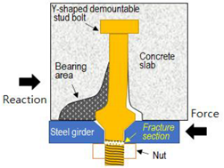
Welded headed studs are used to connect steel girders and concrete slabs in steel composite bridges. However, environmental problems related to welded shear connectors have been reported, including noise and dust generation during the replacement and demolition of damaged or worn concrete slabs. To overcome these issues, demountable shear connectors that enable easy replacement of damaged or worn concrete slabs must be developed. However, conventional bolted shear connectors mainly use embedded nuts, which cannot be used in structures such as bridges because initial slip occurs and the stiffness and shear resistance strength are relatively low. To address these issues, this paper proposes a bolted shear connector that integrates the embedded nut part into the stud bolt and has a tapered shape at the bottom of the expansion column. For performance verification in regard to static shear strength and slip displacement, push-out tests were performed according to Eurocode-4, and the performance of the proposed stud bolt was compared to those of conventional welded headed studs and embedded nut-style bolted shear connectors. In addition, an analytical review was performed using the ABAQUS program for the 1/4 axisymmetric model of the push-out test. As a result of applying the material nonlinear model and the surface contact analysis, the load-slip displacement of each analysis model showed a tendency extremely similar to the experimental results. The proposed demountable bolted shear connector exhibited excellent shear performance and can be used as a satisfactory replacement for conventional welded studs because it meets slip displacement and ductility standards.
1. Introduction
In South Korea, research has been actively conducted on precast slabs since the 2000s with the objectives of providing high-quality cast-in-place slabs and shortening construction times, and interest in prefabricated bridges has greatly increased recently. Most studies on precast slabs have been focused on joints between slabs along the bridge length (prestressing or loop joints), and the concept of prefabrication has rarely been applied to shear connections between girders and slabs.
Shear connectors in bridges are very important elements that perform the roles of both girders and slabs by resisting the horizontal shear that occurs between the girders and slabs of the superstructure due to flexure. In steel composite bridges, the most commonly used shear connectors in the world are welded headed studs.
In bridge structures, the service lives of the steel girders are very long compared to those of the concrete slabs, in which wear of material increases greatly with time. Therefore, even though many studies have been conducted on improving slab performance, wear and damage to concrete slabs accelerate due to the increasing number of heavy vehicles and the use of deicing chemicals, and slabs require replacement much sooner than steel girders. Because of the various problems that occur when slabs are replaced, there are sometimes cases in which entire bridges are demolished and rebuilt, including the girders, which still have sufficient remaining lifespans. Therefore, in terms of life cycle cost (LCC), the overall bridge lifespan can be increased considerably, and its economic feasibility can be greatly improved by replacing the slabs several times over the life of the steel girders.
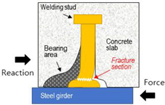
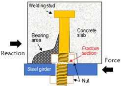
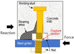
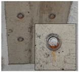
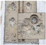
Precast concrete slabs have many advantages over cast-in-place concrete slabs, including quality management and shortened building time during construction; however, during the process of demolition and removal to rebuild the slabs, the worn slabs must be cut and crushed for removal, which is not advantageous. Generally, when replacing a damaged or worn concrete slab, the slab between the girders is firstly cut with a wheel saw or diamond wire saw and demolished. Then, the slab that is connected to the top of the girder, i.e., the concrete part that is integrated by the shear connector, is crushed with a breaker or water jet equipment and removed. The demolition process of precast slabs is the same as that of cast-in-place slabs because the slabs are connected to the welded studs at the steel girders by non-shrink mortar via a slab shear pocket. During demolition, a breaker is used to crush the part of the concrete slab that is linked to the shear connector, causing a lot of noise and fine dust, which increases secondary damage in urban areas. In addition, as the work continues for a long time, an extended period of traffic control is necessary until the reconstruction is complete, which inconveniences citizens and causes significant economic losses. When this work is performed, the welded studs can be bent or damaged by the impact of the breaker, and ultimately the slab must be rebuilt after cutting all the conventional studs and welding new studs. Using a water jet to perform crushing minimizes the damage to the shear connectors, but takes a long time and increases the cost. In addition, the large amount of water that is used generates a great deal of concrete sludge, which can lead to environmental pollution. Therefore, for complete prefabricated construction in the future, it will be necessary to develop a technology for demountable shear connections between girders and slabs such that the slab can be easily demounted during slab rebuilding rather than simply performing new construction.
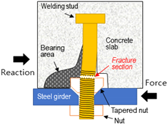
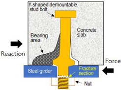
This report proposes demountable stud bolts that can replace traditional welded stud shear connectors. In the case of the existing bolted separable shear connector, a friction grip as well as a single- and double-nut type buried nut are applied as shown in Chapter 2. In this case, it is essential to machine the thread on the stud column to the upper part where the buried nut is fastened. This causes a loss of the cross-sectional area of the stud, and a large slip occurs even at an initial low load owing to the flange hole machining tolerance. For this reason, compared to general welding studs, the initial stiffness is low and fracture tends to occur at a relatively low load. Recently, to improve this problem, research has been conducted on the locking-bolt or locking-nut type separable shear connector. These methods showed excellent promising results, as reviewed in Chapter 2 of the related studies. However, these approaches also require processing the thread on the stud column up to a certain height in order to be fastened with the embedded nut to the bolt embedded in the concrete floor plate. Therefore, in this study, a stud bolt having a Y-shape in which the buried nut part is integrated with the stud column is presented so as to play the role of a buried nut and to avoid any cross-sectional loss of the stud column, to compensate for the problems presented above. The proposed detachable stud bolt has a Y-shape tapered surface, thus it can prevent the loss of stiffness by suppressing the initial slip. In addition, it is a structure that can fully exhibit the function of a separable stud, while also significantly improving shear resistance by increasing the cross-sectional area of the mid-enlarged stud column. Above all, the key feature is that the stud bolt has no threads at the interface between the concrete slab and the upper flange of the girder, which receives the greatest shear force. In this study, to verify the performance of the proposed stud bolts, we conducted experimental and analytical comparative studies for general welding studs and embedded nut type of demountable studs. To verify the performance of the proposed stud bolts, push-out tests were performed by fabricating the main type of shear connection specimen that is used in sheer testing on steel composite slabs. The proposed bolts were compared to the conventional connectors that have welded studs and embedded nuts, and their static strength and slip displacement were examined. In addition, finite element (FE) analysis was performed on each specimen model to confirm the reliability of the experimental results using analytical methods.
2. Review of Previous Studies of Steel Composite Bridge Shear Connectors
Studies on shear connectors in steel girder and concrete slab composite bridges can be classified into those focusing on the welded style and the bolted style according to the joining style of the shear connector of the steel girder. Many studies have been performed on the welded style of shear connectors since the 1960s, mainly using styles with welded headed studs or Perfobond shear connectors, as shown in Figure 1.
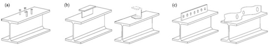
Figure 1.
Shear connector types: (a) headed stud; (b) T and channel; (c) Perfobond.
Various experimental and analytical research on headed studs in relation to welded style shear connectors has been performed over the past few decades. Based on the results of these studies, design formulas for shear connectors have been presented in the design standards of various countries. Recently, numerous studies on the group behavior of large-diameter studs and welded studs have been performed [1,2,3], and there have been many investigations of Perfobond rib shear connectors with .channels, Г and L shapes [4,5], and Y shapes [6].
Lee et al. [1] and Shim [2] studied easy slab removal and efficient precast slab shear pocket arrangement using welded connectors with diameters of 25–30 mm, i.e., larger than those of welded studs (19 or 22 mm), which are mainly used in steel composite bridges. Shim [2] performed push-out tests on welded studs with a maximum diameter of 30 mm and compared the static and fatigue behavior results with the design formulas. Even when large-diameter studs were used, there were no problems with static strength or ductility, but the fatigue strength was slightly lower than that of normal studs, requiring improvements to the welding. In addition, it was concluded that the Eurocode-4 design strength can be applied even when using studs with large diameters of up to 30 mm. In order to use large-diameter (25–30 mm) shear connectors in steel composite bridges, Nguyen and Kim [3] performed push-out tests and FE analysis using ABAQUS to compare their design strength to that of conventional headed welded studs using Eurocode-4 and AASHTO LRFD [7]. They verified the FE analysis model using the results of push-out tests by Gattesco and Giuriani [8] and Lee et al. [9] and presented an approach that uses FE analysis in detail.
Chung and Lee [10] derived the shear strength assessment formula for a Г-shaped Perfobond rib shear connector by performing experimental research and FE analysis using ABAQUS on shear specimens with Г-shaped Perfobond rib shear connectors. During use, the connectors showed very strong stiffness, and they retained considerable ductility after reaching the ultimate load. The shear strength of the ¬-shaped Perfobond rib shear connectors was determined by the effect of the ground pressure resistance on the concrete at the bottom of the shear connector, the effect of the dowel action of the concrete shaped by the rib hole, the effect of the transverse rebar, and the dowel effect at the rib head plate. In addition, studies on Perfobond ribs have been conducted by numerous researchers in South Korea, including Chung et al. [11], Kim and Koo [12], Ahn et al. [13], and Kyung et al. [14]. Ahn et al. [13] proposed that through-rebars must be reinforced in order to improve usability and resolve reduced durability when Perfobond rib shear connectors are used in composite sections and there are holes.
Cho et al. [15] performed push-out tests to assess the static behaviors of shear connectors with regard to lightweight concrete precast slabs. To prevent cracking in the bedding layer, which is a major cause of reduced strength in precast slabs that have bedding layers, a shear key was installed between the precast slabs and bedding layer, and the bedding layer was fixed in the transverse direction. Despite limited testing, it was reported that reductions in the strength of shear connectors with bedding layers were prevented by installing shear keys. Lee et al. [16] reviewed the static strength and fatigue design formulas for shear connector designs in various countries and used two-face symmetric shear tests and analysis to reevaluate the single face asymmetric shear tests by Slutter and Fisher [17] that are the basis for the fatigue design curve presented in AASHTO LRFD. In total, 150 data were collected from 12 fatigue test programs around the world, and comparative analysis was performed. The analysis results confirmed that most of the experimental results exceeded those of Slutter and Fisher [17]. From this finding, it was determined that the AASHTO LRFD fatigue design produces conservative results because a relatively low fatigue load bearing capacity was measured due to imbalances during the one-sided shear tests at that time.
In addition to experimental research, various studies have been conducted using analytical methods. Prakash et al. [18] compared the experimental results of other researchers through 3D FE nonlinear analysis of steel–concrete composite girders. A concrete damaged plasticity (CDP) model was loaded in the ABAQUS program to simulate the cracking and fatigue modes of concrete in a stable manner. Chaudhari [19] compared analytical reviews regarding the use of the ABAQUS smeared crack model and CDP model on a concrete cube 3D model with a size of 150 mm. Yan et al. [20] assessed the ultimate strength behaviors of steel–concrete composite structures through 16 push-out experiments and bending tests on six beams. In addition, they verified the experimental results through FE analysis.
In contrast, relatively few studies have been performed on bolted shear connectors in comparison to welded shear connectors, and national design codes do not contain rules on bolted shear connectors. Bolted shear connectors are presented as alternatives that enable quick installation and removal of precast slabs, as shown in Figure 2 and Figure 3 [21].
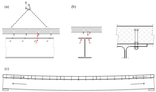
Figure 2.
Prefabrication with use of casted bolted shear connectors [21]: (a) assembling method; (b) connection after assembling; (c) assembled composite beam.
Figure 3.
Demountable bolted shear connector types: (a) friction grip bolt; (b) without embedded nut; (c) single embedded nut; (d) double embedded nuts [21]; (e) LNSC [22]; (f) novel bolted connector [23]; (g) LBDSC [24].
Figure 3 shows the shapes of the main bolted shear connectors that have been studied previously. The connecting action is affected by the presence of embedded nuts in the concrete slab, number of embedded nuts (single or double embedded nuts), and resultant preloading of bolts. Friction grip bolts transfer shear force through friction between the steel girder flange and the concrete slab caused by the bolt load. Initially, at less than a certain level of shear force, resistance occurs via frictional force; then, slipping occurs and the shear connector ultimately resists shear. Because the initial slip resistance increases in proportion to the bolt load, the slab receives high compressive stress in two directions. Therefore, there are many cases in which helix-shaped reinforcers are used around the bolt holes to reinforce the concrete, which receives high local stress [21].
Marshall et al. [25] performed static push-out tests and composite beam tests using friction grip bolts with a diameter of 16 mm to evaluate the effects of various concrete strengths. In these tests, a bolt load of approximately 90 kN was used, and a friction coefficient of approximately 0.45 was reported in the case of precast slabs. Hawkins [26] performed single bolt shear tests on stud bolts without embedded nuts. The bolt diameter and height and the concrete strength were used as the experimental parameters. It was concluded that the shear strength was low, at 80% of the shear strength of welded studs, and the shear stiffness due to the slip around the hole perforation was only 15%. Kwon [27] used friction grip shear connectors that employ high-tensile bolts to reinforce a conventional non-composite bridge. Static and fatigue tests were performed through single bolt shear tests using ASTM A325 bolts (nominal tensile strength of 830 MPa). Specifically, five million rounds of fatigue tests were performed at a bolt load of 175 kN and a shear stress range of 241 MPa. The results showed that shear resistance was similar to or better than those of conventional headed studs, and good performance was seen in terms of fatigue strength, as the shear connectors did not fracture even after five million rounds. Also, compared to the non-composite beam tests, the load bearing capacity increased by almost 50%, even at a shear connection ratio of less than 30%. Loqman et al. [28] studied the structural behavior of steel composite beam systems that use bolted shear connectors. It was recommended that a high-tensile force grip bolt (HTFGB) be used rather than a normal bolt shear connector to increase the shear performance. Citing the study results of other researchers, the ultimate strength of the composite beam with regard to HTFGBs was reported to be 66% of the tensile strength of high-tensile force bolt shear connectors. When grip bolts are used, initial slipping occurs in an amount equal to the clearance tolerance between the steel beam and precast concrete hole diameter and the shear connector diameter. A low level of shear force is resisted when the initial slipping occurs due to the friction of the contact surface between the steel beam and concrete and the load of the introduced bolts; then, after all of the slip equaling the amount of hole clearance has occurred, the direct shear resistance of the shear connector, which is in a composite state, occurs. Accordingly, a load–slip prediction formula for HTFGB shear connectors in composite beams was presented.
Chung et al. [29] fabricated 12 bolted shear specimens and performed push-out tests to study the methods of designing bolted shear connectors for steel girders and precast concrete slabs. The major variables that influenced the shear resistance of the bolted shear connectors were considered to be the design strength of the precast slab, strength of the non-shrink mortar, stud diameter, and screw height, and the bedding layer height was fixed at 20 mm. A static strength assessment formula was presented as a function of the stud shear connector diameter and bedding layer thickness. The experimental results showed that when the nut height matched the bedding layer, reductions in static strength and fatigue performance occurred, but when the nut height was located within the bedding layer or slab, there was no great difference. This experimental research was used to propose a design formula that can be utilized when the nut height is within the bedding layer. Lee and Bradford [30] used M20 bolts (level 8.8) according to Eurocode-4 to perform push-out tests on two specimens. A bolt load of 145 kN and a concrete compressive strength of 48 MPa were used. All bolts in both specimens fractured, and ductile behavior was seen due to a large amount of slip. It was concluded that this phenomenon was caused by the hole tolerance due to the slab being drilled at a diameter of 24 mm, which was larger than the bolt diameter of 20 mm. Lam et al. [31] studied bolted studs using demountable shear connectors to replace welded studs. Eight push-out tests were performed on four studs with diameters of 19 mm and various concrete strengths, and it was confirmed that the slab could easily be demounted after the tests. The failure mode was shear fracture of the shear connectors and concrete crushing. The ductile behavior of the bolted shear connectors was excellent, but the stiffness was low and the shear resistance performance was similar to that of welded studs.
Pavlović [21] investigated the shear performance and ductile behavior of bolted shear connectors for use in precast concrete. They conducted a review of literature in related fields, a preliminary investigation, and various push-out tests on shear specimens and presented a satisfactory analytical approach regarding the experimental results using FE analysis and various variable studies. The failure modes and mechanical behaviors of welded studs and bolted shear connectors were compared in detail through an analytical approach. Csillag and Pavlović [32] used push-out test specimens with steel girder and fiber reinforced plastics (FRP) composite slabs to assess the shear loads, stiffnesses, and ductile behaviors of demountable bolted shear connectors. Ajax, Lindapter Hollo-Bolt, and injected steel-reinforced resin (SRR) connectors were used as the demountable bolted shear connectors for comparison. The failure mode and load–slip behavior of each shear connector were assessed and compared with the FE analysis results.
Suwaed and Karavasilis [22] proposed a locking nut shear connector (LNSC) that manufactured a conical nut with a tapered lower surface of the nut embedded in a concrete slab to minimize slip and fastened it to the tapered hole of the upper flange of a steel girder. In addition, for the synthesis of a precast concrete slab and steel girder, a method of synthesizing using separately manufactured plug concrete, a plate washer, stud head and nut, and grouting was applied to the shear pocket. Push-out tests showed that shear resistance, stiffness, and slip capacity were significantly higher than weld studs, along with good stiffness and strength against slab lift. In most failure modes, shear failure occurred at the stud bolt thread on the top of the buried nut. The authors also proposed a design equation for predicting shear resistance with an absolute error of less than 8%. Although this method shows excellent performance in terms of initial slip and stiffness raised as problems with general bolt-type shear connectors, it is expected that the manufacturing process will be extremely complicated because there are many of these third-part elements in practical field application. In the case of some specimens, inconsistent load-slip behavior is considered to be influenced by the manufacturing process of these various members. Yang et al. [23] proposes a novel bolted connector method using a bolt fastened to the flange hole of a steel beam and a bolt embedded in a concrete slab, that is, two high-tensile bolts, albeit connected with a coupler such that these bolts can be combined within the concrete slab. The influence of bolt strength, diameter, and flange hole tolerance was examined through push-out tests. In the case of the concrete slab, negligible damage was observed and the failure occurred where the bolts connected to the steel beam flanges. In the case of the welding stud method, slip displacement of about 8 mm occurred; however, most of the cases where the novel bolted connector was applied showed a tendency to break with a small slip deformation of less than 5 mm. The maximum slip under the breaking load increased as the bolt diameter increased. Furthermore, the authors suggested that little correlation exists between shear stiffness and bolt diameter and strength, while shear stiffness tends to decrease as the tolerance between bolt shank and bolt hole increases. Kozma et al. [33] proposed a method using an embedded mechanical coupler device as a demountable stud connector. This was reported by Yang et al. [23]. It is similar to the novel bolted connector method proposed by [23]. In addition, it was compared with the friction-grip bolt type including a cylinder system in a concrete slab. The overall failure mode was shear failure of the bolt, bearing deformation in the steel beam flange hole, and damage to thread penetration. The initial stiffness was greater in the case where pretension was not introduced when tightening the bolts; however, the total slip amount was as small as the initial slip amount in the case where pretension was not introduced. In both cases, the magnitude of the breaking load showed similar results. Although it resists up to friction bearing capacity owing to pretension, subsequently, the slip is greatly increased owing to the tolerance of the flange hole, and as a result, the pressure and shear deformation in the steel beam flange at the time of failure increase. Kozma et al. [33] suggested that a larger tolerance is acceptable without lowering the load carrying capacity when the hole is filled by applying an epoxy resin. Jun et al. [24] proposed a locking-bolt demountable shear connector (LBDSC) structure as a detachable stud. The LBDSC structure has a thread at both ends and a bolt with a conical seat lug in the middle inserted into the counter-sunk hole of the steel beam flange and fastened. Jun et al. [24] evaluated the effect of pipe thickness, concrete slab strength, and injected grout on the shear resistance, initial stiffness and ductility of LBDSC through nine horizontal shear experiments. Overall, it was established that the initial stiffness and the ductility effect owing to slip were sufficient, although, as the tube became thinner, it was greatly deformed at the end in contact with the upper surface of the steel beam flange and showed a tendency to break. This phenomenon is due to the inevitable hole margin between the counter-sunk hole drilled in the steel beam flange and the conical seat lug of the bolt during manufacturing, which is a major occurrence.
3. Push-Out Tests and Analysis of Results
3.1. Shear Specimen Fabrication and Material Properties
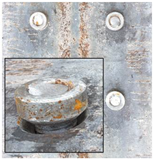
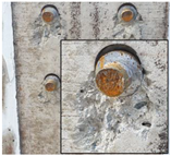
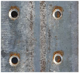
Generally, when performing strength assessment experiments on the shear performance of steel composite bridges, push-out tests using shear specimens are generally performed rather than composite beam experiments. In South Korea, no clear push-out test regulations have been established, but many researchers follow the testing method in Annex B of Eurocode-4 [34]. Therefore, Eurocode-4 was also referenced in this study, and the specimen width and length were set to 600 and 750 mm, respectively. The slab thickness was set to 220 mm, using the minimum slab thickness regulations presented in the South Korean concrete design standards (Ultimate Strength Design Method, [35]). For the shear specimen slab, a cast-in-place slab was used, and Figure 4 provides a diagram of the specimen design.
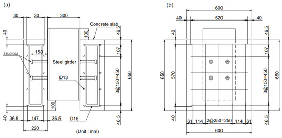
Figure 4.
Geometric details for push-out specimens: (a) section view; (b) side view.
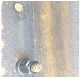
A total of 18 specimens were fabricated, and the steel girder H beams were composed of SM490A grade steel with a 300(B) × 300(H) × 10(tw) × 15(tf) cross-section. The specimens were classified according to the type of shear connector, as shown in Figure 5 and Table 1. S1 had a conventional welded headed stud. S2 had a bolted shear connector in which a hexagonal nut was fastened in an embedded manner. For S3, a Y-shaped nut was fabricated instead of a hexagonal nut, and the upper flange of the steel girder was cut into a Y-shape so that there was a wedging effect when the embedded nut was fastened. Two models were considered, using cutting angles of 20° and 45°. S4 had a shape similar to that of S3, but the Y-shaped nut was integrated into the stud bolt instead of using an embedded nut, and the two Y-shape angles were the same as the cutting angles, at 20° and 45°. The shear connectors used in S1, S2, and S3 were conventional welded headed stud products composed of SS275 material. S4 used SM45C (non-heat-treated), which is a structural steel that is easy to cut and machine into threads. The shear connector of each specimen had a slab embedding length of 150 mm and diameter of 22 mm.
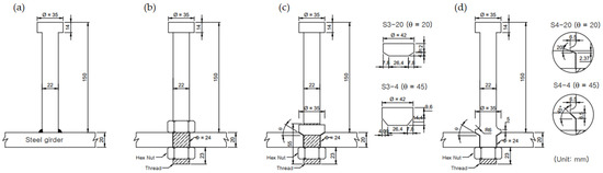
Figure 5.
Shear connector shapes: (a) welding stud; (b) single-nut stud bolt; (c) tapered-nut stud bolt; (d) Y-shaped stud bolt.

Table 1.
Detail information for specimens and studs.
Figure 6 shows the manufacturing process for the specimens. For the bolted shear connector specimens, drilling was performed at a diameter of 24 mm because 22 mm bolts were used due to the machining standards of the steel girder hole. In cases 3 and 4, holes with a diameter of 24 mm were drilled to fasten the stud bolts to the upper flange of the steel girder. Then, a Y-shaped taper was machined in the upper part to match the set angle so that the tapered, inclined surface was completely in contact when the bolts were fastened. After the bolts and nuts were fastened, the bolted shear connector specimens were fabricated by placing the rebar, installing the formwork, placing the concrete, and curing the concrete. Three specimens were fabricated for each case, and four shear connectors were arranged on each side of the slab in a 2 × 2 array so that a total of eight were used in each specimen. The slab concrete design strength was 30 MPa.
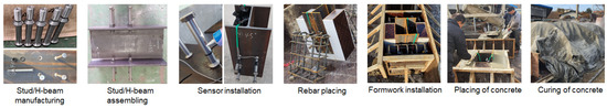
Figure 6.
Shear specimen fabrication process.
3.2. Experimental Method and Measurement Conditions
In the push-out tests, a vertical load was applied to the steel upper part of the specimens in a static loading fashion using a 5 MN dynamic universal testing machine (UTM). Load control was applied at a rate of 50 kN/min, and displacement control was applied at a rate of 1.5 mm/min. Figure 7 provides an overview of the push-out tests performed at the Myongji University Hybrid Structure Testing Center. Monotone increasing displacement control was performed on specimens #1 and #2 for each experimental case. For specimen #3 in each case, 5–40% of the expected ultimate load was applied 25 times at a rate of 50 kN/min, and then monotone increasing displacement control was performed until failure. Figure 8 depicts the overall loading process. Regarding the sensor placement, six strain gauges were installed on each of the specimens at the bodies of the embedded shear connectors, and four strain gauges were installed on the surface of the concrete, as shown in Figure 9. To measure the slip displacement caused by the loading, linear variable differential transformers (LVDTs) were installed at both the front and back to measure the relative displacement between the steel girders and slab concrete. As shown in Figure 9a, the LVDT was restrained with a magnetic mount on the lower part of the web of the H-beam and the relative displacement with the rigid base floor was measured. The LVDT displacement value was simultaneously measured with the UTM control load using data acquisition equipment, and the load-displacement graph presented in the analysis of the experimental results was used by averaging these two displacement values.
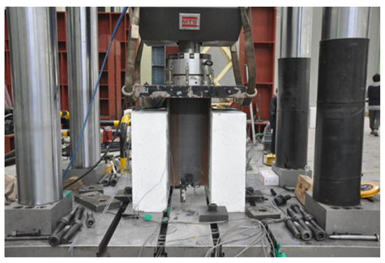
Figure 7.
Push-out test set-up.
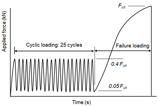
Figure 8.
Loading process [21].
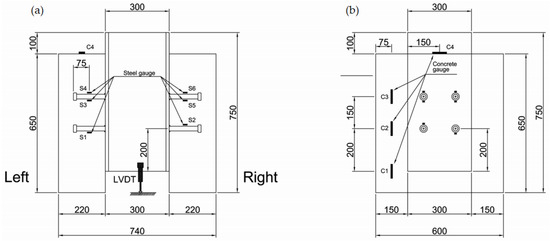
Figure 9.
Sensor locations: (a) LVDT and stud strain gauge installation; (b) concrete strain gauge installation.
3.3. Experimental Results and Analysis
Figure 10 presents the static experiment results for each of the experimental cases, and Table 2 and Table 3 compare the overall experimental results. The load–slip displacement curve for each experiment case is the displacement curve of the LVDTs installed in the specimens to measure the relative slip between the steel girders and concrete slab and the UTM load rather than the load–displacement values of the UTM. The stiffnesses of the repeated load parts of specimen #3 of models S1–S3 exhibit low consistency, unlike that of specimen #3 of model S4, because the values from the two displacement gauges installed at the front and back of the specimens were averaged, and it was confirmed that the repeated loading by the UTM was controlled normally like it was for S4. In the case of model S4, the step-wise decrease in strength at the ultimate load was caused by the fracturing of the shear connector bolt.
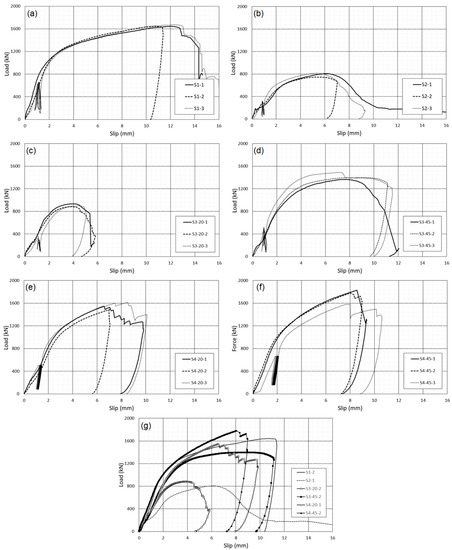
Figure 10.
Load–slip relationship curves: (a) S1 (welding stud); (b) S2 (single-nut stud bolt); (c) S3-20 (tapered-nut stud bolt, 20°); (d) S3-45 (tapered-nut stud bolt, 45°); (e) S4-20 (Y-shaped stud bolt, 20°); (f) S4-45 (Y-shaped stud bolt, 45°); (g) all models.
Table 2.
Test results.
Table 3.
Test results and fracture model of shear connector.
In the experiment results in Table 2, the ultimate strengths of all models except for S4-45 are lower than that of the conventional welded studs (S1). In particular, for the single-nut method, in which fastening is performed with an embedded hexagonal nut and which has been the main demounting method used, the ultimate strength is only 47.8%. The double-nut method was not investigated in this study, but due to the nature of the conventional nut method, the stud bolt thread is present in the nut contact surface with the upper flange, and consequently, the shear strength is greatly lowered due to the reduction in cross-section. Particularly in the case of S2, more initial slip occurred than in the other models, which seems to have caused significant reduction in not only the stiffness, but also the ultimate strength.
On the contrary, unlike the embedded nut models (S1 and S2), the integrated Y-shaped stud bolt model (S4) has a higher ultimate strength equal to 93.9% of the ultimate strength of model S1 at a wedge angle of 20° and 104.6% at a wedge angle of 45°. Model S4–45 shows a level of performance similar to that of S1 in terms of stiffness in the elastic interval before yielding. The other models have lower stiffnesses than model S1, but model S4–45 displays sufficient stiffness through integrated behavior similar to that of model S1 because not only was there no reduction in the stud shear surface due to the use of an integrated Y-shape rather than an embedded nut, but also the initial slip was blocked due to the wedging effect that occurred when the bolt was fastened because of its 45° angle.
However, model S4–45 shows a maximum slip displacement equal to 65.4% of the maximum slip displacement of model S1. In addition, looking at the failure mode, tensile fracturing occurred in the fastening part of the stud bolt (the interface between the steel girder lower flange and nut) rather than shear fracturing at the embedded position of the stud (the interface between the upper flange of the steel girder and concrete slab). Of course, an average maximum slip displacement of 8.76 mm satisfies the relevant standards by exceeding 6 mm, which is the minimum amount of ductile deformation listed in the road bridge design standards of South Korea. However, it is necessary to induce brittle bolt failure via ductile fracturing in the embedded part.
It appears that proposed S4 model can adequately replace the conventional welded stud method in terms of strength if the brittle fracturing of the fastening part due to bolt tension is improved. It is thought that this model will be very useful for deconstructing and reconstructing worn bridge slabs because the slab concrete can be easily demounted.
As shown in Figure 11, the slip displacement caused by the initial repeated load was set as the initial value (), and the slip displacement () during maximum shear failure was defined as a displacement amount corresponding to 90% of the failure load (Equation (1)).
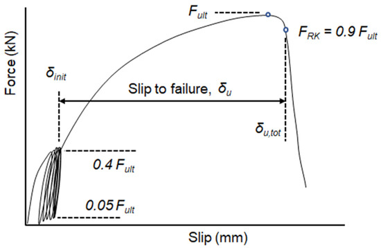
Figure 11.
Definitions of failure load and slip displacement [21].
4. FE Analysis and Result
4.1. Analysis Method and Modeling
FE analysis was performed to assess the experimental results analytically. ABAQUS [36], which is a general analysis program capable of analyzing concrete composites and contact, was used as the FE analysis software. The explicit method was utilized to increase the convergence of the solutions for material nonlinear analysis and contact analysis. Previous studies have shown that ABAQUS/Explicit is more effective than ABAQUS/Standard in many nonlinear problems, such as concrete material cracking and failure. The explicit method achieves faster convergence than the implicit method for each incremental analysis because it is not necessary to perform inverse matrix conversions on the stiffness matrix, and the analysis time can be shortened by using mass scaling or increasing the loading rate.
The element mesh size is very important for obtaining accurate analysis results. If the mesh size is large, the analysis time can be shortened, but the solution accuracy may be poor. Therefore, it is very important to select a suitable mesh size that can increase the degree of accuracy. To increase the solution accuracy, 3D solid elements were employed in this study. For the concrete slabs, steel beams, and shear studs, 3D eight-node elements were used to mitigate the solution convergence problem. For the rebar, T3D2 truss elements were used, and an embedded state was applied to the concrete slab element. The FE analysis model was modeled as a 1/4 model of the actual shear specimen, accounting for axial symmetry, as shown in Figure 12.
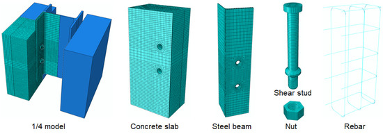
Figure 12.
FE model and mesh for push-out specimen (ex: S4-45).
The analysis was performed in two stages. Firstly, the bolt load was used to analyze the H beam, stud bolt, and nut models. Then, continuous analysis was performed on the model of the entire system, using the bolt stress as an initial value. For the bolt load, a load corresponding to 67% of the minimum tensile strength of each stud (95 kN) was used [37].
4.2. Material Model
4.2.1. Structural Steel, Rebar, and Shear Connectors
The stress–strain linear model proposed by Nguyen and Kim [4] and Pavlović [21] was used as the material model for the steel members. The stress–strain curves for the structural steel (H beam) and rebar were modeled as two-line curves as shown in Figure 13a. Complete plastic behavior occurs after yielding in these models, and the mechanical behaviors with regard to tension and compression are both assumed to be symmetric in the same way. The steel beams were SM490A structural steel, and they had an elastic modulus of 210 GPa and a yield strength of 316.5 MPa. However, the rebar steel type was SD40, with an elastic modulus of 192.8 GPa and a yield strength of 542.6 MPa. A Poisson’s ratio of 0.3 was used for both. The material model of the welded headed studs was modeled as a three-line stress–strain curve as shown in Figure 13b. This model considers three-stage linear behavior consisting of an elastic region, a strain softening region, and a general yield region.
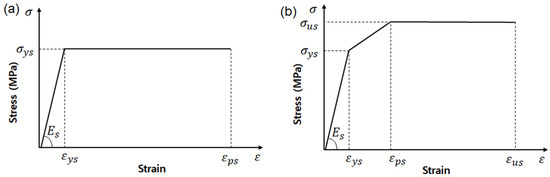
Figure 13.
Stress–strain relationship: (a) bi-linear stress–strain curve (H beam, rebar); (b) tri-linear stress–strain curve (stud).
Table 4 shows the material property values of each of the steel members that were used in the FE analysis. The values obtained from actual coupon tests were used for the welded studs, stud bolts, and rebar. Regular nominal values were used for the H beams. During the FE analysis, the material damage and failure options were not utilized on the material models for each steel material, unlike the concrete material model.
Table 4.
Summary of steel component properties.
4.2.2. Concrete
The nonlinear behavior of the concrete material can be expressed by a concrete equivalent uniaxial stress–strain curve, as shown in Figure 14. In the case of compressed concrete, this curve was divided into three parts. The first part was assumed to be in the elastic range up to the proportional limit stress. The proportional limit stress was calculated as , as given in Eurocode-4. Here, is the concrete compressive strength of a cylinder test piece. is , and is the concrete compressive strength of a cubic test piece. The strain that corresponds to is 0.0022. The initial elastic modulus was calculated using Equation (2), an empirical equation given by Eurocode-2 [38]. The Poisson ratio of the concrete was considered to be 0.2 [3].
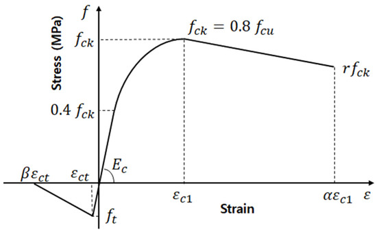
Figure 14.
Schematic stress–strain relationship for concrete material.
The second part of the curve is a nonlinear parabola that starts at the proportional limit stress 0.4 and extends to the concrete compressive strength . This curve can be determined by Equation (3), which is given in Eurocode-2.
Here, , (the strain at the maximum compressive stress ), and .
The third part of the stress–strain curve of the compressed concrete is the declining region from to . Here, is the reduction coefficient given by Ellobody et al. [39]. is given variously in the range of 0.5–1.0 depending on the amount of compressive strength in a cubic concrete test piece (30–100 MPa). The value of 0.85 that was used by Nguyen and Kim (2009) was employed in this study as well. During failure corresponding to , the ultimate strain of the concrete was the same as . According to Eurocode-2 and BS 8110 [40], is (). Ellobody et al. [39] used 11 as the value of for a concrete model that was confined in a dense state due to the rebar (confined concrete). Nguyen and Kim (2009) used various values for correction between the load-slip curve derived through analysis and the experimental data, and they found an optimal match at (). We used the same values Nguyen and Kim [4] did.
The concrete stress of the tensile region was assumed to increase linearly in proportion to the strain until cracking occurred in the concrete. In addition, the tensile stress of the concrete after cracking linearly decreased to 0. It is possible to obtain a numerical solution more easily by using the tension stiffening effect. Nguyen and Kim [4] used a strain of 0.005 () at a stress of 0 to avoid unstable behavior during analysis, and the same value was used in this study.
To verify the push-out tests through FE analysis, we used the CDP model, which can be used in the ABAQUS material library. This material model is suitable for materials that have different tensile and compressive strengths. In this material model, the tension and compression of the yield part of the concrete stress–strain curve are handled separately. Table 5 shows each of the variable values in the CPD model that was used in this study. We utilized values that were well-suited to the overall push-out experiment results by performing additional variable analysis on the dilation angle and .
Table 5.
ABAQUS/Explicit parameters in a CDP model.
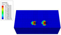
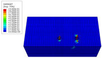
In addition, Figure 15 depicts the damage model for concrete compression and tension in ABAQUS. The principle behind the damage parameters is described by the stress–strain diagram under non-elastic conditions, as shown in this figure.
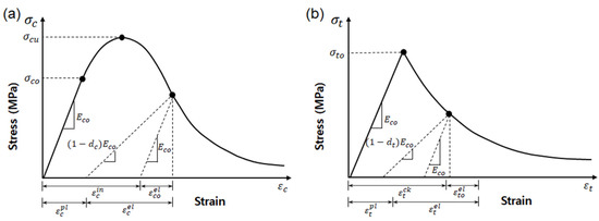
Figure 15.
Concrete damage parameters: (a) compression; (b) tension.
The compression failure conditions () and amount of concrete strain during cracking () were calculated using Equations (4)–(7) based on Figure 15.
The concrete damage parameters are divided into compressive stress () and tensile stress (), and they are each shown as functions of stress and plastic strain in Equations (8) and (9). Each damage parameter has a constant value that is and . Here, value 0 means that there is no concrete damage, and 1.0 means complete failure.
4.3. Load, Boundary Conditions, Interactions, and Constraint Conditions
As depicted in Figure 16, the analysis was performed using 1/4 model of the actual push-out specimens. Therefore, axisymmetric boundary conditions were used on the Y- and Z-axes, as shown in Figure 16a. For the boundary conditions, multi-point constraint conditions were applied to the entire bottom surface of the concrete, which is the supporting surface of the specimen, separately from the axisymmetric boundary conditions, and all of the degrees of freedom of the standard node were confined. For the load, to minimize the strain rate caused by the loading rate, a rigid body was modeled at the top of the steel beam, and displacement control (U1) was performed in parallel to the X-axis, where the shear connector was located. The displacement control was increased using a smooth amplitude function. Based on the actual experimental results, different values were used for the maximum analysis displacement of each analysis model.
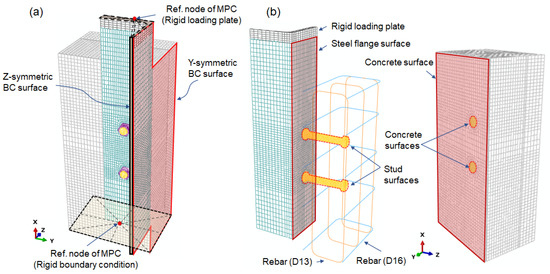
Figure 16.
Constrain, interaction surfaces, and boundary conditions (BC): (a) boundary conditions and constraints; (b) surfaces in contact interaction.
Because the push-out specimens contained connections between heterogenous materials, it was necessary to perform contact analysis on the contact surfaces where the members formed the connections. Therefore, contact interactions were used for all the slip surfaces between members. The contact surfaces were defined as the steel beam and concrete slab, stud bolt and nut (or embedded nut), steel beam top surface, tapering surface of the Y-shaped stud bolt, stud (head and column) surface, concrete internal stud embedded surface, etc., and each contact surface was set as a surface-to-surface interface. Table 6 summarizes the contact properties of the contact surface interactions of each analysis model. A friction coefficient of 0.3 was used for the contact surfaces (H beam–nut and bolt–nut thread) caused by the bolt–nut fastening in all models, and that of 0.14 was used for the other contact surfaces. However, in the case of the S1 (welded stud) model, when a friction coefficient of 0.14 was used on the stud and concrete contact surface, the strength was greatly decreased compared to the experimental results in the plastic region after yielding; therefore, a friction coefficient of 0.3 was used. For the other models, using 0.14 produced results that were similar to the actual experimental results. The reason for this result is thought to be because threads were machined on the stud bolts used in models S2–S4, and the reduction in strength after yielding was large compared to that in model S1, which involved without any thread machining; therefore, using a friction coefficient of 0.14 produced similar results.
Table 6.
Contact properties for each interactions of analytical models.
Regarding the interaction, the penalty contact method was used for the mechanical constraint formulation in all cases, and finite sliding was utilized for the sliding formulation. Table 6 summarizes the tangent and normal values of the contact properties.
4.4. Comparison of Analysis Results and Experimental Values
As shown in Figure 17, the number of studs was changed to eight for comparison of the FE analysis results, which were obtained using the 1/4 model, at the same load as the actual experiment results. In addition, the FE analysis results were compared by overlapping the starting displacement of each model by the initial slip amount, taking into account the initial slip () caused by the load stabilization in the initial elastic region experiments.
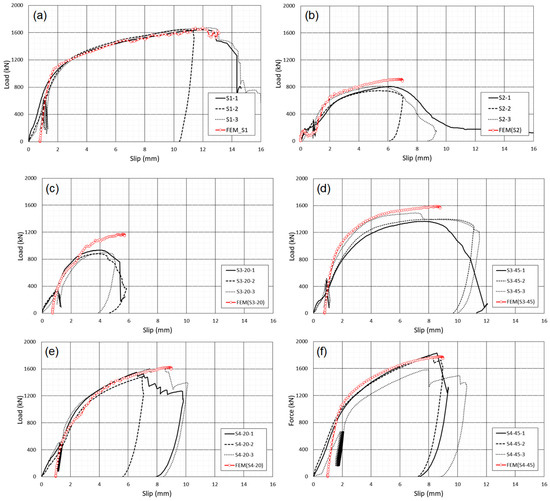
Figure 17.
FE analysis results (load–slip relationship): (a) S1 (welding stud); (b) S2 (single-nut stud bolt); (c) S3-20 (tapered-nut stud bolt, 20°); (d) S3-45 (tapered-nut stud bolt, 45°); (e) S4-20 (Y-shaped stud bolt, 20°); (f) S4-45 (Y-shaped stud bolt, 45°).
For model S1, the analysis values of the yield strength and initial stiffness were slightly higher than the experimental values, which is thought to have occurred because the effect of the weld bead was counted larger than it should be. For model S2, it can be seen that the stiffness of the stud bolt was manifested after an initial slip of up to 1 mm occurred at low loads due to the tolerance between the diameters of the hole in the upper flange of the H beam and stud bolt. The amount of load resistance at an initial slip of less than 1 mm can be considered to be caused by the friction effect resulting from the bolt load. For model S3-20, all the analysis results match the experimental results well, except that the ultimate load in the analysis was larger than the experimental value. In the actual experimental results, models S3 and S4 both have higher initial stiffnesses and ultimate loads when the Y-shape is 45° than when it is 20°. It can be seen that in both 45° models, the stiffness that resists initial slip becomes larger than that in the 20° models due to the wedge effect caused by the bolt load.
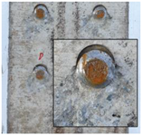
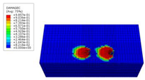
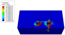
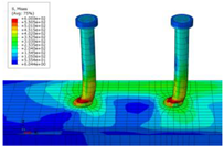
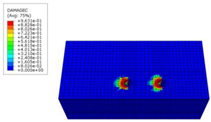
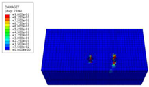
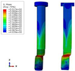
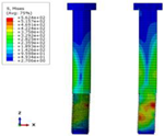
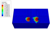
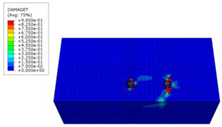
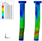
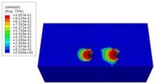
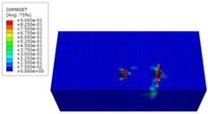
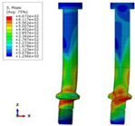
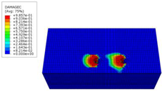
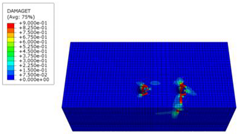
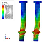
Table 7 shows the compressive and tensile failure modes of the concrete slab and the von Mises stress of the shear connectors in each model. In models S1–S3, it can be seen that shear fracturing occurred due to the concentration of stress at the same locations at which the studs fractured in the experiments. However, in model S4, considerable yielding occurred due to shear in the Y-shape location, but the actual experiments differed in that failure occurred due to the tensile fracturing of the nut fastening part. Because the material damage and failure options were not used on the stud bolts in the FE analysis, the amount of stress continually increased until the end of the analysis, and it is impossible to know where the actual fracturing began. However, considering that the equivalent stress increased greatly above and below the Y-shaped expansion in the analysis results, it is thought that the actual fracturing first occurred due to the concentration of stress caused by notches and the reduction in the cross-sectional area in the lower part in which the threads were located. Model S4 has a cross-section that is integrated via the Y-shape, and its shear resistance cross-section is larger than those of the other models; therefore, it was able to resist a high ultimate load. Overall, the analysis results match the actual experimental results well in terms of the concrete failure state, shear connector deformation and fracture location, load–slip displacement curve, etc.
Table 7.
FE analysis results (damage mode of concrete and shear connector).
Table 8 compares experimental and FE analysis results for ultimate load and maximum slip displacement for each model. In the case of FE analysis, it is difficult to directly compare with the experimental results because displacement control analysis was performed; however, it is possible to compare the ultimate load. In the case of the buried nut-type S2 and S3 models, the contact surfaces are more complicated than other models, hence, the analysis results show a maximum error of 29.3% compared to the experimental results. In the case of the S4 model proposed through the analysis, it showed reliable results throughout analysis with an error of less than 4.4%. Overall, the analysis results showed a higher breaking load than the experimental results.
Table 8.
Comparison of experimental and analysis results (maximum load and slip displacement).
5. Conclusions
The objective of this study was to resolve the problems of initial slip and relatively low shear resistance strength in the embedded nut-style bolted shear connectors that are mainly used today. We developed a demountable stud bolt shear connector that has an expanded section in which the embedded nut is integrated into the stud bolt as well as a Y-shaped tapering surface and conducted push-out tests by fabricating shear specimens to verify the strength performance. The specimens were fabricated using not only the regular welded headed studs that are listed in the design standards, but also embedded nut-style bolted shear connectors, and a comparison was performed. In addition, FE analysis was conducted on each specimen model, and the results were compared with the experimental results. The results that were derived from this study can be summarized as follows:
- (1)
- Welded headed studs (model S1) are superior to conventional bolted shear connectors in terms of ductile deformation and shear strength.
- (2)
- In the conventional bolted shear connectors, fracturing occurred in both the nut that was embedded in the concrete slab and the stud bolt threads, which are located at the upper flange interface, and the fracture load was very low, at 47.8% of the fracture load of model S1. In addition, the failure slip deformation was 50.8% of the failure slip deformation of model S1 at 6.03 mm.
- (3)
- Looking at the Y-shaped embedded nut shear connectors (model S3), the failure load of the model with a Y-shape angle of 20° was larger than that of model S2, but the slip deformation during failure was very small at 4.27 mm. On the other hand, the failure load of the model with a 45° angle was lower than that of the welded stud and higher than that of the embedded nut model (model S2).
- (4)
- The ultimate load of the Y-shaped integrated demountable stud bolt (model S4) was 196% (20°)–219% (45°) of the ultimate load of the conventional bolted shear connector (model S2), and it was higher than that of the welded stud (model S1) at 93.9% (20°)–104.6% (45°). The amount of slip deformation during failure was 6.91 mm (20°) and 7.76 mm (45°), exceeding the design standard of 6 mm and showing ductile behavior. However, the stud bolt experienced fracturing at the threads of the nut fastening part, and it is thought that additional research on this aspect is needed.
- (5)
- The South Korean bridge design standard for shear connector ductile deformation, which is 6 mm, was satisfied by all models except for model S3–20.
- (6)
- The FE analysis results obtained using the concrete CDP models matched the experimental load–slip behaviors well overall. In particular, it was possible to confirm the failure mode of the shear connectors adequately in an analytical manner.
- (7)
- Model S4, which was ultimately proposed in this paper, could prevent initial slip and increases in the initial stiffness and failure strength by not using an embedded nut and by introducing a bolt load to remove the tolerance caused by the wedging effect. Therefore, the use of Y-shaped demountable stud bolt shear connecters can resolve the problems of increased initial slip, decreased stiffness, and reduced ultimate failure strength caused by the hole tolerance that mainly occurs in conventional embedded nuts.
In conclusion, the Y-shaped demountable stud bolt shear connectors presented in this paper can be used as replacements for welded stud shear connectors because they exhibit a ductile behavior that exceeds the design standards and a shear resistance strength higher than that of conventional welded stud bolts. Further, they enable quick installation and removal of slabs. However, brittle fracturing of the stud bolts occurred at the nut fastening portions in the experiments conducted on the proposed model (model S4). Therefore, it is necessary to induce the failure mode to cause shear fracturing in the slab concrete embedded part. To do so, additional research on optimizing the Y-shape is needed.
From a practical engineering perspective, the top-flange of girders receives tensile stress in the negative moment section of the middle support of a continuous bridge, unlike in the positive moment section of a span center. To apply the bolted demountable shear connector proposed in this study, the tensile cross-sectional area of the upper flange of the girder was reduced in the negative moment part because of the perforated hole; therefore, further review is required.
Author Contributions
Conceptualization, D.-S.J.; Methodology and analysis, S.-H.P. and D.-S.J.; Experiments and investigation, J.-W.H. and C.-Y.K.; Writing–original draft preparation, D.-S.J., S.-H.P. and T.-H.K.; Writing–review and editing, S.-H.P. and T.-H.K.; Visualization, D.-S.J. and S.-H.P.; Supervision, D.-S.J.; All authors have read and agreed to the published version of the manuscript.
Funding
Korea Agency for Infrastructure Technology Advancement: 21CTAP-C164073-01.
Acknowledgments
This study was conducted with financial support (21CTAP-C164073-01) from the Korea Agency for Infrastructure Technology Advancement, part of the Ministry of Land, Infrastructure and Transport. We would like to express our gratitude for this support.
Conflicts of Interest
The authors declare no conflict of interest.
References
- Lee, P.G.; Shim, C.S.; Yoon, T.Y. Static behavior of large stud shear connectors. J. Korean Soc. Steel Construct. 2003, 15, 611–620. (In Korean) [Google Scholar]
- Shim, C.S. Experiments on limits state design of large stud shear connectors. KSCE J. Civil Eng. 2004, 8, 313–318. [Google Scholar] [CrossRef]
- Nguyen, H.T.; Kim, S.E. Finite element modeling of push-out tests for large stud shear connectors. J. Construct. Steel Res. 2009, 65, 1909–1920. [Google Scholar] [CrossRef]
- Maleki, S.; Bagheri, S. Behaviour of channel shear connectors, Part I, Experimental study. J. Construct. Steel Res. 2008, 64, 1333–1340. [Google Scholar] [CrossRef]
- Ahn, J.H.; Lee, C.G.; Won, J.H.; Kim, S.H. Shear resistance of the Perfobond shear connector depending on concrete strength and rib arrangement. J. Construct. Steel Res. 2010, 66, 1295–1307. [Google Scholar] [CrossRef]
- Kim, S.H.; Choi, K.T.; Park, S.J.; Park, S.M.; Yung, C.Y. Experimental shear resistance evaluation of Y-type Perfobond rib shear connector. J. Construct. Steel Res. 2013, 82, 1–18. [Google Scholar] [CrossRef]
- AASHTO LRFD Bridge Design Specifications, 4th ed.; AASHTO: Washington, DC, USA, 2007.
- Gattesco, N.; Giuriani, E. Experimental study on stud shear connectors subjected to cyclic loading. J. Construct. Steel Res. 1996, 38, 1–21. [Google Scholar] [CrossRef]
- Lee, P.G.; Shim, C.S.; Chang, S.P. Static and fatigue behavior of large stud shear connectors for steel–concrete composite bridges. J. Construct. Steel Res. 2005, 61, 1270–1285. [Google Scholar] [CrossRef]
- Chung, C.H.; Lee, H.S. Evaluation of shear strength of the type Perfobond rib shear connectors. J. Korean Soc. Civ. Eng. 2005, 25, 879–888. (In Korean) [Google Scholar]
- Chung, C.H.; Lee, H.S.; You, S.K.; Choi, W.H. Experimental analysis of type Perfobond rib shear connection between steel tubes and concrete deck. J. Korean Soc. Civ. Eng. 2005, 25, 201–212. (In Korean) [Google Scholar]
- Kim, H.Y.; Koo, H.B. Composite behavior of Perfobond rib shear connector for steel-concrete decks. J. Korean Soc. Civ. Eng. 2006, 26, 91–97. (In Korean) [Google Scholar]
- Ahn, J.H.; Choi, K.T.; Kim, S.H.; Kim, S.H. Shear capacity of corrugated rib shear connector. J. Korean Soc. Civ. Eng. 2008, 28, 375–381. (In Korean) [Google Scholar]
- Kyung, K.S.; Lee, S.Y.; Jeong, Y.J.; Kwon, S.C. Fatigue behavior of steel-concrete composite bridge deck with Perfobond rib shear connector. J. Korean Soc. Civ. Eng. 2010, 30, 71–80. (In Korean) [Google Scholar]
- Cho, S.K.; Lee, J.M.; Youn, S.G.; Choi, Y.W. Behavior of stud shear connectors in precast deck using lightweight concrete. J. Korean Soc. Steel Construct. 2008, 20, 227–236. (In Korean) [Google Scholar]
- Lee, K.C.; Yoon, K.Y. Assessment and recommendation of fatigue design codes for stud shear connectors in composite bridge. J. Korean Soc. Hazard Mitig. 2009, 9, 15–21. (In Korean) [Google Scholar]
- Slutter, R.G.; Fisher, J.W. Fatigue Strength of Shear Connectors; Highway Research Record No. 147; National Research Council: Washington, DC, USA, 1966. [Google Scholar]
- Prakash, A.; Anandavalli, N.; Madheswaran, C.K.; Rajasankar, J.; Lakshmanan, N. Three dimensional FE model of stud connected steel-concrete composite girders subjected to monotonic loading. Int. J. Mech. Appl. 2011, 1, 1–11. [Google Scholar]
- Chaudhari, S.V.; Chakrabarti, M.A. Modeling of concrete for nonlinear analysis using finite element code ABAQUS. Int. J. Comput. Appl. 2012, 44, 14–18. [Google Scholar]
- Yan, J.B.; Li, Z.X.; Xie, J. Numerical and parametric studies on steel-elastic concrete composite structures. J. Construct. Steel Res. 2017, 133, 84–96. [Google Scholar] [CrossRef]
- Pavlović, M.S. Resistance of Bolted Shear Connectors in Prefabricated Steel-Concrete Composite Decks. PhD Thesis, University of Belgrade, Republic of Serbia, 2013. [Google Scholar]
- Suwaed, A.S.H.; Karavasilis, T.L. Novel Demountable Shear Connector for Accelerated Disassembly, Repair, or Replacement of Precast Steel-Concrete Composite Bridges. J. Bridge Eng. 2017, 22, 04017052. [Google Scholar] [CrossRef] [Green Version]
- Yang, F.; Liu, Y.; Jiang, Z.; Xin, H. Shear performance of a novel demountable steel-concrete bolted connector under static push-out tests. Eng. Struct. 2018, 160, 133–146. [Google Scholar] [CrossRef]
- He, J.; Suwaed, A.S.H.; Vasdravellis, G. Horizontal pushout tests and parametric analyses of a locking-bolt demountable shear connector. Structures 2022, 35, 667–683. [Google Scholar] [CrossRef]
- Marshall, W.T.; Nelson, H.M.; Banarjee, H.K. An experimental study of the use of high strength friction-grip bolts as shear connectors in composite beams. Struct. Eng. 1971, 49, 171–178. [Google Scholar]
- Hawkins, N. Strength in shear and tension of cast-in-place anchor bolts. Anchorage Concr. SP-103 1987, 103, 233–255. [Google Scholar]
- Kwon, G. Strengthening Existing Steel Bridge Girders by the Use of Postinstalled Shear Connectors. Ph.D. Thesis, The University of Texas, Austin, TX, USA, 2008. [Google Scholar]
- Loqman, N.; Safiee, N.A.; Bakar, N.A.; Nasir, N.A.M. Structural behavior of steel-concrete composite beam using bolted shear connectors: A review. MATEC Web Conf. 2018, 203, 06010. [Google Scholar] [CrossRef] [Green Version]
- Chung, C.H.; Kim, J.S.; Park, H.S.; Joo, B.C. Strength of bolt type shear connector in precast deck composite bridges. J. Korean Soc. Civ. Eng. 2005, 25, 787–800. (In Korean) [Google Scholar]
- Lee, M.; Bradford, M.A. Sustainable composite beam behaviour with deconstructable bolted shear connectors. In Proceedings of the 2013 Composite Construction in Steel and Concrete VII, Palm Cove, North Queensland, Australia, 28–31 July 2013. [Google Scholar]
- Lam, D.; Dai, X.; Saveri, E. Behaviour of demountable shear connectors in steel-concrete composite beams. In Proceedings of the 2013 Composite Construction in Steel and Concrete VII, Palm Cove, North Queensland, Australia, 28–31 July 2013. [Google Scholar]
- Csillag, F.; Pavlović, M.S. Push-out behaviour of demountable injected vs. blind-bolted connectors in FRP decks. Compos. Struct. 2021, 270, 114043. [Google Scholar] [CrossRef]
- Kozma, A.; Odenbreit, C.; Braun, M.V.; Veljkovic, M.; Nijgh, M.P. Push-out tests on demountable shear connectors of steel-concrete composite structures. Structures 2019, 21, 45–54. [Google Scholar] [CrossRef] [Green Version]
- EN 1994-1-1; Eurocode-4: Design of Composite Steel and Concrete Structures, Part 1-1: General Rules and Rules for Buildings. European Committee for Standardization (CEN): Brussels, Belgium, 2004.
- KDS 24-14-20:2016; Korean Design Standard. Korea Construction Standards Center: Goyang-si, Korea, 2016.
- ABAQUS; Dassault Systèmes Simulia Corp.: Johnston, RI, USA, 2020.
- KDS 24-14-30:2016; Korean Design Standard. Korea Construction Standards Center: Goyang-si, Korea, 2016.
- EN 1992-1-1; Eurocode-2: Design of Concrete Structures, Part 1-1: General Rules and Rules for Building. European Committee for Standardization (CEN): Brussels, Belgium, 2004.
- Ellobody, E.; Young, B.; Lam, D. Behaviour of normal and high strength concrete-filled compact steel tube circular stub columns. J. Construct. Steel Res. 2006, 62, 70615. [Google Scholar] [CrossRef]
- BS 8110, Parts 1, 2. Code of Practice for Design and Construction; British Standards Institution: London, UK, 1997.
Publisher’s Note: MDPI stays neutral with regard to jurisdictional claims in published maps and institutional affiliations. |
© 2022 by the authors. Licensee MDPI, Basel, Switzerland. This article is an open access article distributed under the terms and conditions of the Creative Commons Attribution (CC BY) license (https://creativecommons.org/licenses/by/4.0/).