
UCLAONT: Ontology-Based UML Class Models Verification Tool

 ,
,  , , , and
Abstract
1. Introduction
2. Related Work
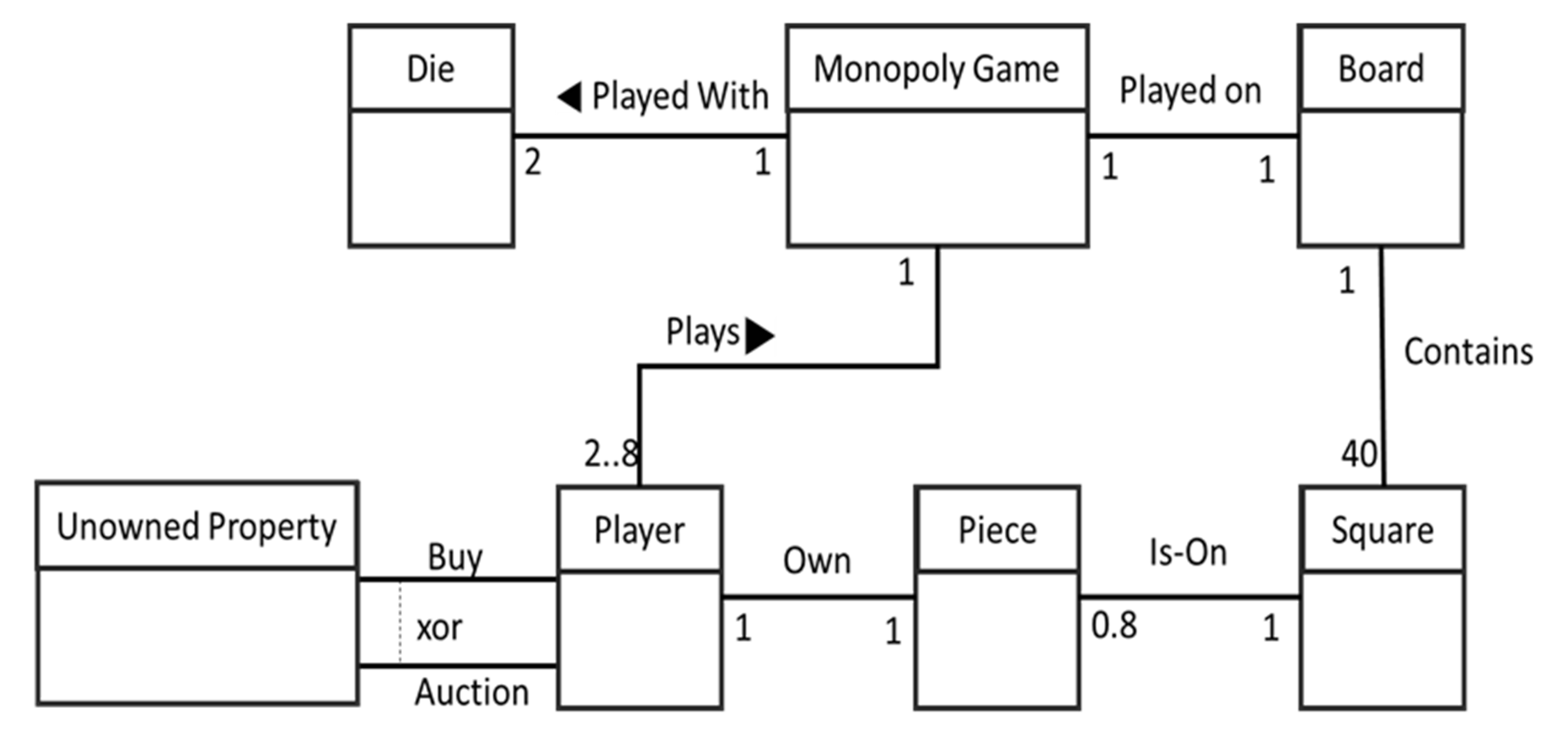
3. Running Example
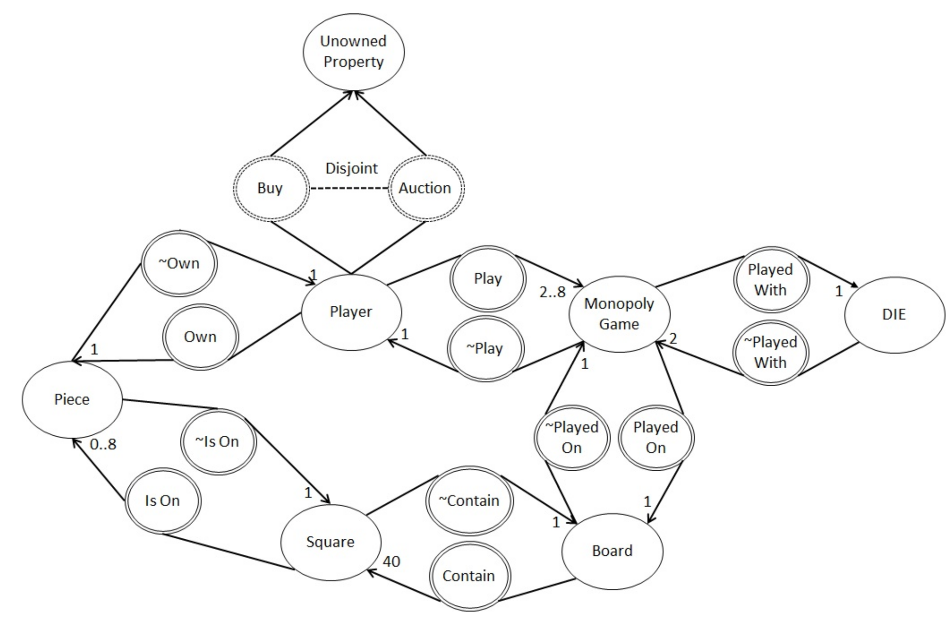
Ontology-Based Finite Satisfiability
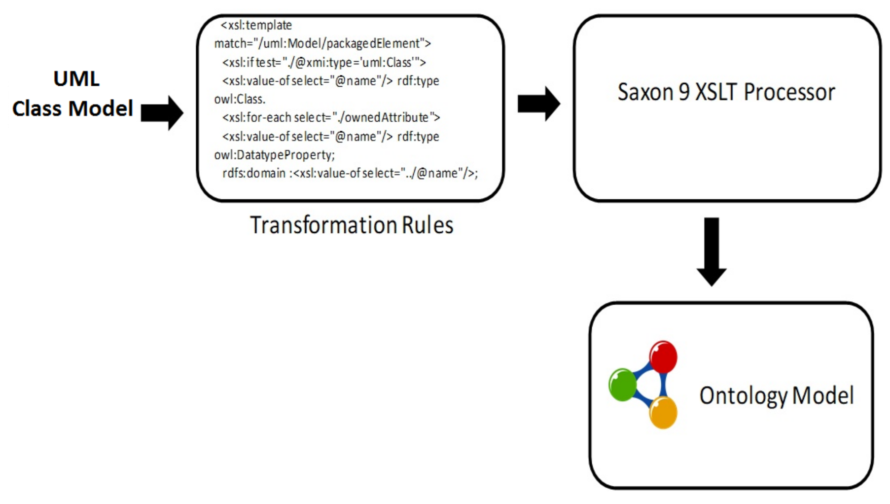
4. UCLAONT Architecture
4.1. Transformation Component
4.1.1. Transformation Rules
4.1.2. Class and Attributes
- Rules (XSLT)
- <xsl:if test="./@xmi:type=’uml:Class’">
- :<xsl:value-of select="@name"/> rdf:type owl:Class.
- </xsl:if>
- Example (XMI)
- <packagedElement xmi:type="uml:Class"
- xmi:id="_0bvU1IwREeeHI8ZOY9KM8g" name="Player"/>
- Output (OWL)
- :Player rdf:type owl:Class.
4.1.3. Generalization Relationship
- Rules (XSLT)
- <xsl:for-each select="./generalization">
- :<xsl:value-of select="../@name"/> rdfs:subClassOf
- :<xsl:value-of select="key(’Classid’,@general)/@name"/>.
- </xsl:for-each>
- Example (XMI)
- <packagedElement xmi:type="uml:Class" xmi:id="_LxECg" name="A"/>
- <packagedElement xmi:type="uml:Class" xmi:id="_LxECh" name="B">
- <generalization xmi:type="uml:Generalization" xmi:id="_LxEC"
- general="_LxECg"/>
- </packagedElement>
- Output (OWL)
- :A rdf:type owl:Class .
- :B rdf:type owl:Class ;
- rdfs:subClassOf :A
4.1.4. Association
- Rules (XSLT)
- <xsl:if test="./@xmi:type=’uml:Association’">
- <xsl:choose>
- <xsl:when test="mf:check(./ownedEnd/@xmi:id,../ownedRule/
- @constrainedElement)"> </xsl:when>
- <xsl:otherwise>
- :<xsl:value-of select="@name"/> rdf:type owl:ObjectProperty;
- <xsl:for-each select="./ownedEnd">
- <xsl:if test="position()=1">
- rdfs:domain :<xsl:value-of select="key(’Classid’,@type)/@name"/>;
- </xsl:if>
- <xsl:if test="position()!=1">
- rdfs:range :<xsl:value-of select="key(’Classid’,@type)/@name"/>.
- </xsl:if>
- </xsl:for-each>
- :inv-<xsl:value-of select="@name"/> rdf:type owl:ObjectProperty;
- owl:inverseOf :<xsl:value-of select="@name"/>.
- Example (XMI)
- <packagedElement xmi:type="uml:Class" xmi:id="_C" name="Player"/>
- <packagedElement xmi:type="uml:Association" xmi:id="_D"
- name="Plays" memberEnd="_CE">
- <ownedEnd xmi:type="uml:Property" xmi:id="_CE" type="_CJ"
- association="_D"/>
- <ownedEnd xmi:type="uml:Property" xmi:id="_Cc"
- type="_Cf" association="_D"/> </packagedElement>
- <packagedElement xmi:type="uml:Class" xmi:id="_E"
- name="Monopoly Game"/>
- Output (OWL)
- :Plays rdf:type owl:ObjectProperty;
- rdfs:domain :Player;
- rdfs:range :Monopoly Game;
- :inv-Plays rdf:type owl:ObjectProperty;
- rdfs:domain :Monopoly Game;
- rdfs:range :Player;
- :Plays owl:inverseOf :inv-Plays
4.1.5. Multiplicities
- Rule (XSLT)
- <xsl:if test="position()!=1">
- <xsl:value-of select="key(’Classid’,./preceding-sibling::∗
- [1]/@type)/@name"/>
- owl:equivalentClass [ rdf:type owl:Class ;
- owl:intersectionOf ( [ rdf:type owl:Restriction
- owl:onProperty :<xsl:value-of select="../@name"/>;
- owl:onClass :<xsl:value-of select="key(’Classid’,@type)/@name"/>;
- owl:minQualifiedCardinality "<xsl:choose>
- <xsl:when test="not(./lowerValue)"> 1 </xsl:when>
- <xsl:when test="./lowerValue/@value"> <xsl:value-of select=".
- /lowerValue/@value"/> </xsl:when> <xsl:otherwise> 0 </xsl:otherwise>
- </xsl:choose>"^^xsd:nonNegativeInteger] [ rdf:type owl:Restriction ;
- owl:onProperty :<xsl:value-of select="../@name"/>;owl:onClass
- :<xsl:value-of select="key(’Classid’,@type)/@name"/>;
- owl:maxQualifiedCardinality "
- <xsl:choose>
- <xsl:when test="not(./upperValue)"> 1 </xsl:when>
- <xsl:when test="./upperValue/@value"><xsl:value-of select="./
- upperValue/@value"/> </xsl:when>
- <xsl:otherwise> 0 </xsl:otherwise>
- </xsl:choose>"^^xsd:nonNegativeInteger])]
- </xsl:if>
- Example (XMI)
- <ownedEnd xmi:type="uml:Property" xmi:id="_bc1" association="Plays">
- <upperValue xmi:type=" uml:LiteralInteger" xmi:id="_b1" value="1"/>
- <lowerValue xmi:type="uml:LiteralInteger" xmi:id="_b2" value="1"/>
- </ownedEnd>
- Output (OWL)
- rdfs:range [rdf:type owl:Class ;
- owl:intersectionOf ([rdf:type owl:Restriction; owl:onProperty :Plays;
- owl:onClass:Monopoly Game ;owl:minQualifiedCardinality
- "1"^^xsd:nonNegativeInteger] [rdf:type owl:Restriction ;
- owl:onProperty :Plays ; owl:onClass :Monopoly Game ;
- owl:maxQualifiedCardinality "1"^^xsd:nonNegativeInteger])] .
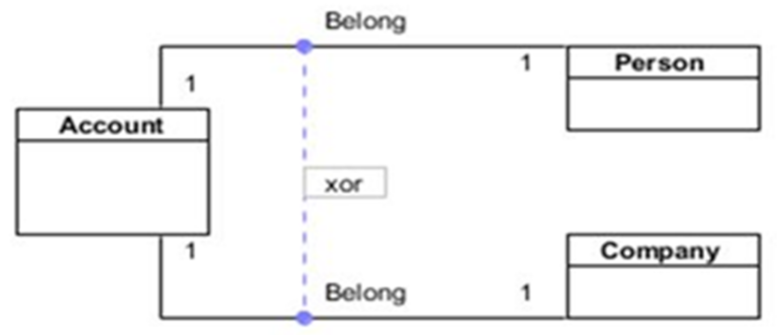
4.1.6. XOR Constraint
- Rule (XSLT)
- <xsl:if test="@name=’xor’">
- <xsl:variable name="abc" select="tokenize(@constrainedElement,’ ’)"/>
- <xsl:variable name= "key1" select="key(’consid’,$abc[1])/@association"/>
- <xsl:variable name= "key2" select="key(’consid’,$abc[2])/@association"/>
- <xsl:variable name="Ass1" select="key(’Classid’,$key1)/@name"/>
- <xsl:variable name ="Ass2" select="key(’Classid’,$key2)/@name"/>
- <xsl:variable name="Ass1End" select="key(’Classid’,$key1)/@memberEnd"/>
- <xsl:variable name ="Ass2End" select="key(’Classid’,$key2)/@memberEnd"/>
- <xsl:variable name="leftAssownedend1" select="mf:searchobject($Ass1End,2)"/>
- <xsl:variable name="leftclassid1" select="key(’consid’,$leftAssownedend1)
- /@type"/>
- <xsl:variable name="rightAssownedend1" select="mf:searchobject($Ass1End,1)
- "/>
- <xsl:variable name="rightclassid1" select="key(’consid’,$rightAssownedend1)
- /@type"/>
- <xsl:variable name="rightAssownedend2" select="mf:searchobject($Ass2End,1)"/>
- <xsl:variable name="rightclassid2" select="key(’consid’,$rightAssownedend2)
- /@type"/>
- Example (XMI)
- <ownedRule xmi:type="uml:Constraint" xmi:id="_Q1" name="xor"
- constrainedElement="_Q2 _Q1">
- <specification xmi:type="uml:LiteralString" xmi:id="_Q2" value=""/>
- </ownedRule>
- <packagedElement xmi:type="uml:Class" xmi:id="_Q1" name="Player"/>
- <packagedElement xmi:type="uml:Association" xmi:id="_Q3" name="Buy">
- </packagedElement>
- <packagedElement xmi:type="uml:Association" xmi:id="_Q6" name="Auction">
- </packagedElement>
- <packagedElement xmi:type="uml:Class" xmi:id="_Q11" name="Auction"/>
- Output (OWL)
- :Unowned Property rdf:type owl:Class.
- :Players rdf:type owl:Class.
- :Auction rdf:type owl:ObjectProperty ;
- :Buy rdf:type owl:ObjectProperty ;
- owl:propertyDisjointWith :Auction.
- Rule (XSLT)
- <xsl:when test ="$Ass1=$Ass2">
- :<xsl:value-of select="$Ass1"/> rdf:type owl:ObjectProperty.
- :<xsl:value-of select="key(’Classid’,$leftclassid1)/@name"/>
- owl:equivalentClass [rdf:type owl:Class ;
- owl:unionOf ([rdf:type owl:Class ;
- owl:intersectionOf ([rdf:type owl:Class ;
- owl:complementOf [rdf:type owl:Restriction ;
- owl:onProperty :<xsl:value-of select="$Ass1"/> ;
- owl:someValuesFrom :<xsl:value-of select="key(’Classid’,$rightclassid2)
- /@name"/>;]]
- [rdf:type owl:Restriction;owl:onProperty :<xsl:value-of select="$Ass1"/> ;
- owl:someValuesFrom :<xsl:value-of select="key(’Classid’,$rightclassid1)
- /@name"/>;])]
- [ rdf:type owl:Class ;
- owl:intersectionOf ( [ rdf:type owl:Class ;
- owl:complementOf [ rdf:type owl:Restriction ;
- owl:onProperty :<xsl:value-of select="$Ass1"/> ;
- owl:someValuesFrom :<xsl:value-of select="key(’Classid’,$rightclassid1)
- /@name"/>;]]
- [ rdf:type owl:Restriction ;
- owl:onProperty :<xsl:value-of select="$Ass1"/>;
- owl:someValuesFrom :<xsl:value-of select="key(’Classid’,$rightclassid2)
- /@name"/>;])])]. </xsl:when>
- Example (XMI)
- <packagedElement xmi:type="uml:Class" xmi:id="_L1" name="Account"/>
- <packagedElement xmi:type="uml:Association" xmi:id="_L2" name="Belong">
- </packagedElement>
- <packagedElement xmi:type="uml:Class" xmi:id="_L10" name="Person"/>
- <packagedElement xmi:type="uml:Class" xmi:id="_L11" name="Company">
- </packagedElement>
- Output (OWL)
- :Account
- owl:equivalentClass [rdf:type owl:Class ; owl:intersectionOf ([rdf:type owl:Class;
- owl:intersectionOf ([rdf:type owl:Class ; owl:complementOf[ rdf:type owl:Restriction;
- owl:onProperty :Belong; owl:someValuesFrom :Person]] [ rdf:type owl:Restriction;
- owl:onProperty :Travel ; owl:someValuesFrom :CommercialVehicle])]
- [rdf:type owl:Class ; owl:unionOf([rdf:type owl:Restriction;owl:onProperty :Belong;
- owl:someValuesFrom :Vehicle] [ rdf:type owl:Restriction ; owl:onProperty :Travel;
- owl:someValuesFrom :Company])])].
4.2. Reasoning Component
- CheckCardinality()
- for (Graph g :list)
- findPath(g,g.getRange, g.getDomain);
- CriticalCycle=false;
- for (CardFeedBackObject f : fb)
- if (f.criticalCycle)
- CriticalCycle=true;
- return CriticalCycle;
- findPath(Graph g,String r, String s)
- String p=g.getProperty();
- Path.add(p);
- weight=1.0;
- while (true)
- Graph g1=searchInverse(p);
- weight ∗=g.getMax∗(1.0/ g1.getMin);
- g= searchInGraph(g.getRange,g.getProperty);
- r=g.getRange;
- p=g.getProperty;
- Path.add(p);
- if (s=r)
- g1=searchInverse(p);
- weight ∗=g.getMax∗(1.0/ g1.getMin);
- break;
4.3. Feedback Component
5. Experimental Results
6. Conclusions and Future Work
Author Contributions
Funding
Data Availability Statement
Conflicts of Interest
References
- Eriksson, H.E.; Penker, M. Business Modeling with UML; Citeseer: New York, NY, USA, 2000; pp. 1–12. [Google Scholar]
- Rhazali, Y.; Moulay Youssef, H.; Mouloudi, A. A Model transformation from computing independent model to platform independent model in model driven architecture. J. Ubiquitous Syst. Pervasive Netw. 2017, 8, 19–26. [Google Scholar] [CrossRef]
- Biehl, M. Literature study on model transformations. R. Inst. Technol. Tech. Rep. ISRN/KTH/MMK 2010, 291, 1–28. [Google Scholar]
- Mens, T.; Van Gorp, P. A taxonomy of model transformation. Electron. Notes Theor. Comput. Sci. 2006, 152, 125–142. [Google Scholar] [CrossRef]
- Meedeniya, D.A. Correct Model-to-Model Transformation for Formal Verification. Ph.D. Thesis, University of St Andrews, St Andrews, UK, 2013. [Google Scholar]
- Singh, M.; Sharma, A.K.; Saxena, R. An UML+ Z framework for validating and verifying the Static aspect of Safety Critical System. Procedia Comput. Sci. 2016, 85, 352–361. [Google Scholar] [CrossRef][Green Version]
- Dwyer, M.B.; Hatcliff, J.; Robby, R.; Pasareanu, C.S.; Visser, W. Formal software analysis emerging trends in software model checking. In Proceedings of the 2007 Future of Software Engineering, Minneapolis, MN, USA, 23–25 May 2007; pp. 120–136. [Google Scholar]
- Filax, M.; Gonschorek, T.; Ortmeier, F. Correct formalization of requirement specifications: A v-model for building formal models. In International Conference on Reliability, Safety, and Security of Railway Systems; Springer: Berlin/Heidelberg, Germany, 2016; pp. 106–122. [Google Scholar]
- Bowen, J.P. Formal Specification and Documentation Using Z: A Case Study Approach; International Thomson Computer Press: London, UK, 1996; Volume 66. [Google Scholar]
- Beato, M.E.; Barrio-Solórzano, M.; Cuesta, C.E.; de la Fuente, P. UML automatic verification tool with formal methods. Electron. Notes Theor. Comput. Sci. 2005, 127, 3–16. [Google Scholar] [CrossRef]
- Kobryn, C. UML 2001: A standardization odyssey. Commun. ACM 1999, 42, 29–37. [Google Scholar] [CrossRef]
- Dobing, B.; Parsons, J. How UML is used. Commun. ACM 2006, 49, 109–113. [Google Scholar] [CrossRef]
- Shaikh, A.; Wiil, U.K. A feedback technique for unsatisfiable UML/OCL class diagrams. Softw. Pract. Exp. 2014, 44, 1379–1393. [Google Scholar] [CrossRef]
- Shaikh, A.; Wiil, U.K.; Memon, N. Evaluation of tools and slicing techniques for efficient verification of UML/OCL class diagrams. Adv. Softw. Eng. 2011, 2011, 370198. [Google Scholar] [CrossRef]
- Shaikh, A.; Wiil, U.K. UMLtoCSP (UOST): A tool for efficient verification of UML/OCL class diagrams through model slicing. In Proceedings of the ACM SIGSOFT 20th International Symposium on the Foundations of Software Engineering, Cary, NC, USA, 11–16 November 2012; ACM: New York, NY, USA, 2012; p. 37. [Google Scholar]
- Rumbaugh, J.; Jacobson, I.; Booch, G. The Unified Modeling Language Reference Manual; Pearson Higher Education: Hoboken, NJ, USA, 2004. [Google Scholar]
- Batory, D.; Azanza, M. Teaching model-driven engineering from a relational database perspective. Softw. Syst. Model. 2017, 16, 443–467. [Google Scholar] [CrossRef]
- Hilken, F.; Gogolla, M. User Assistance Characteristics of the USE Model Checking Tool. arXiv 2017, arXiv:1701.08471. [Google Scholar] [CrossRef]
- Cabot, J.; Clarisó, R. UML/OCL verification in practice. In Proceedings of the ChaMDE 2008 Workshop Proceedings: International Workshop on Challenges in Model-Driven Software Engineering, Toulouse, France, 28 September–3 October 2008; ACM: New York, NY, USA, 2008; pp. 31–35. [Google Scholar]
- Przigoda, N.; Soeken, M.; Wille, R.; Drechsler, R. Verifying the structure and behavior in UML/OCL models using satisfiability solvers. IET Cyber-Phys. Syst. Theory Appl. 2016, 1, 49–59. [Google Scholar] [CrossRef]
- Shaikh, A.; Clarisó, R.; Wiil, U.K.; Memon, N. Verification-driven slicing of UML/OCL models. In Proceedings of the IEEE/ACM International Conference on Automated Software Engineering, Antwerp, Belgium, 20–24 September 2010; ACM: New York, NY, USA, 2010; pp. 185–194. [Google Scholar]
- Cabot, J.; Claris, R.; Riera, D. Verification of UML/OCL class diagrams using constraint programming. In Proceedings of the 2008 IEEE International Conference on Software Testing Verification and Validation Workshop, Lillehammer, Norway, 9–11 April 2008; pp. 73–80. [Google Scholar]
- Object Management Group. OMG Unified Modeling Language TM (OMG UML) Superstructure v. 2.3. InformatikSpektrum 2010, 21, 758. [Google Scholar]
- Pandey, R. Object constraint language (OCL) past, present and future. ACM Sigsoft Softw. Eng. Notes 2011, 36, 1–4. [Google Scholar] [CrossRef]
- Balaban, M.; Maraee, A. Finite satisfiability of UML class diagrams with constrained class hierarchy. ACM Trans. Softw. Eng. Methodol. (TOSEM) 2013, 22, 24. [Google Scholar] [CrossRef]
- Shaikh, A.; Hafeez, A.; Elmagzoub, M.; Alghamdi, A.; Siddique, A.; Shahzad, B. Ontology-Based Verification of UML Class Model XOR Constraint and Dependency Relationship Constraints. Intell. Autom. Soft Comput. 2021, 27, 565–579. [Google Scholar] [CrossRef]
- Khan, A.H.; Musavi, S.H.A.; Rehman, A.U.; Shaikh, A. Ontology-Based Finite Satisfiability of UML Class Model. IEEE Access 2018, 6, 3040–3050. [Google Scholar] [CrossRef]
- Hafeez, A.; Abbas, S.; Rehman, A. Ontology-Based Transformation and Verification of UML Class Model. Int. Arab. J. Inf. Technol. 2020, 7, 758–768. [Google Scholar] [CrossRef]
- Shaikh, A.; Khan, A.H.; Wagan, A.A.; Alrizq, M.; Alghamdi, A.; Reshan, M.S.A. More Than Two Decades of Research on Verification of UML Class Models: A Systematic Literature Review. IEEE Access 2021, 9, 142461–142474. [Google Scholar] [CrossRef]
- Truong, N.T.; Souquières, J. An approach for the verification of UML models using B. In Proceedings of the 11th IEEE International Conference and Workshop on the Engineering of Computer-Based Systems, Brno, Czech Republic, 27 May 2004; pp. 195–202. [Google Scholar]
- He, H.; Wang, Z.; Dong, Q.; Zhang, W.; Zhu, W. Ontology-based semantic verification for uml behavioral models. Int. J. Softw. Eng. Knowl. Eng. 2013, 23, 117–145. [Google Scholar] [CrossRef]
- Berardi, D.; Calvanese, D.; De Giacomo, G. Reasoning on UML class diagrams. Artif. Intell. 2005, 168, 70–118. [Google Scholar] [CrossRef]
- France, R.; Evans, A.; Lano, K.; Rumpe, B. The UML as a formal modeling notation. Comput. Stand. Interfaces 1998, 19, 325–334. [Google Scholar] [CrossRef]
- Maoz, S.; Ringert, J.O.; Rumpe, B. CD2Alloy: Class diagrams analysis using Alloy revisited. In Proceedings of the International Conference on Model Driven Engineering Languages and Systems, Wellington, New Zealand, 16–21 October 2011; Springer: Berlin/Heidelberg, Germany, 2011; pp. 592–607. [Google Scholar]
- Anastasakis, K.; Bordbar, B.; Georg, G.; Ray, I. On challenges of model transformation from UML to Alloy. Softw. Syst. Model. 2010, 9, 69. [Google Scholar] [CrossRef]
- Artale, A.; Calvanese, D.; Ibáñez-García, A. Full satisfiability of UML class diagrams. In Proceedings of the International Conference on Conceptual Modeling, Vancouver, BC, Canada, 1–4 November 2010; Springer: Berlin/Heidelberg, Germany, 2010; pp. 317–331. [Google Scholar]
- Maraee, A.; Balaban, M. Efficient recognition of finite satisfiability in UML class diagrams: Strengthening by propagation of disjoint constraints. In Proceedings of the 2009 International Conference on Model-Based Systems Engineering, Herzeliya and Haifa, Israel, 2–5 March 2009; pp. 1–8. [Google Scholar]
- Malgouyres, H.; Motet, G. A UML model consistency verification approach based on meta-modeling formalization. In Proceedings of the 2006 ACM Symposium on Applied Computing, Dijon, France, 23–27 April 2006; ACM: New York, NY, USA, 2006; pp. 1804–1809. [Google Scholar]
- Cadoli, M.; Calvanese, D.; De Giacomo, G.; Mancini, T. Finite satisfiability of UML class diagrams by Constraint Programming. CSP Tech. Immed. Appl. (CSPIA) 2004, 2, 2–16. [Google Scholar]
- Cabot, J.; Teniente, E. Incremental integrity checking of UML/OCL conceptual schemas. J. Syst. Softw. 2009, 82, 1459–1478. [Google Scholar] [CrossRef]
- Ledang, H. Automatic translation from UML specifications to B. In Proceedings of the 16th Annual International Conference on Automated Software Engineering (ASE 2001), San Diego, CA, USA, 26–29 November 2001; p. 436. [Google Scholar]
- Marcano, R.; Levy, N. Using B formal specifications for analysis and verification of UML/OCL models. In Workshop on Consistency Problems in UML-Based Software Development, Proceedings of the 5th International Conference on the Unified Modeling Language, Dresden, Germany, 30 September–4 October 2002; Citeseer: New York, NY, USA, 2002; pp. 91–105. [Google Scholar]
- Cabot, J.; Clarisó, R.; Riera, D. UMLtoCSP: A tool for the formal verification of UML/OCL models using constraint programming. In Proceedings of the Twenty-Second IEEE/ACM International Conference on Automated Software Engineering, Atlanta, GA, USA, 5–9 November 2007; ACM: New York, NY, USA, 2007; pp. 547–548. [Google Scholar]
- Bordbar, B.; Anastasakis, K. UML2ALLOY: A Tool for Lightweight Modelling of Discrete Event Systems. In Proceedings of the IADIS International Conference on Applied Computing, Algarve, Portugal, 22–25 February 2005; pp. 209–216. [Google Scholar]
- Nguyen, T.H.; Grundy, J.C.; Almorsy, M. Ontology-based automated support for goal–use case model analysis. Softw. Qual. J. 2016, 24, 635–673. [Google Scholar] [CrossRef]
- Corea, C.; Delfmann, P. Detecting Compliance with Business Rules in Ontology-Based Process Modeling. 2017. Available online: https://aisel.aisnet.org/wi2017/track03/paper/6/ (accessed on 30 August 2021).
- Fellmann, M.; Hogrebe, F.; Thomas, O.; Nüttgens, M. An ontology-driven approach to support semantic verification in business process modeling. In Proceedings of the Modellierung Betrieblicher Informationssysteme (MobIS 2010), Modellgestütztes Management, Dresden, Germany, 15–17 September 2010. [Google Scholar]
- Sun, J.; Wang, H.H.; Hu, T. Design Software Architecture Models using Ontology. In Proceedings of the 23rd International Conference on Software Engineering and Knowledge Engineering, Miami, FL, USA, 7–9 July 2011; pp. 191–196. [Google Scholar]
- Kezadri, M.; Pantel, M. First Steps Toward a Verification and Validation Ontology; Embedded Real Time Software and Systems (ERTS2012): Toulouse, France, 2012; pp. 440–444. [Google Scholar]
- Xu, W.; Dilo, A.; Zlatanova, S.; van Oosterom, P. Modelling Emergency Response Processes: Comparative Study on OWL and UML; Information Systems for Crisis Response and Management, Harbin Engineering University: Harbin, China, 2008; pp. 493–504. [Google Scholar]
- Bahaj, M.; Bakkas, J. Automatic conversion method of class diagrams to ontologies maintaining their semantic features. Int. J. Soft Comput. Eng. (IJSCE) 2013, 2, 65. [Google Scholar]
- Belghiat, A.; Bourahla, M. From UML Class Diagrams to OWL Ontologies: A Graph Transformation Based Approach. In Proceedings of the 4th International Conference on Web and Information Technologies ICWIT 2012, Sidi Bel Abbes, Algeria, 29–30 April 2012; pp. 330–335. [Google Scholar]
- Parreiras, F.S.; Staab, S. Using ontologies with UML class-based modeling: The TwoUse approach. Data Knowl. Eng. 2010, 69, 1194–1207. [Google Scholar] [CrossRef]
- Clarisó, R.; González, C.A.; Cabot, J. Incremental Verification of UML/OCL Models. J. Object Technol. 2020, 19, 3. [Google Scholar] [CrossRef]
- Abbas, M.; Ben-Yelles, C.B.; Rioboo, R. Formalizing UML/OCL structural features with FoCaLiZe. Soft Comput. 2020, 24, 4149–4164. [Google Scholar] [CrossRef]
- Pérez, B.; Porres, I. Reasoning about UML/OCL class diagrams using constraint logic programming and formula. Inf. Syst. 2019, 81, 152–177. [Google Scholar] [CrossRef]
- Goldberg, A.; Radzik, T. A Heuristic Improvement of the Bellman-Ford Algorithm; Technical Report; Computer Science Department, Stanford University: Stanford, CA, USA, 1993. [Google Scholar]


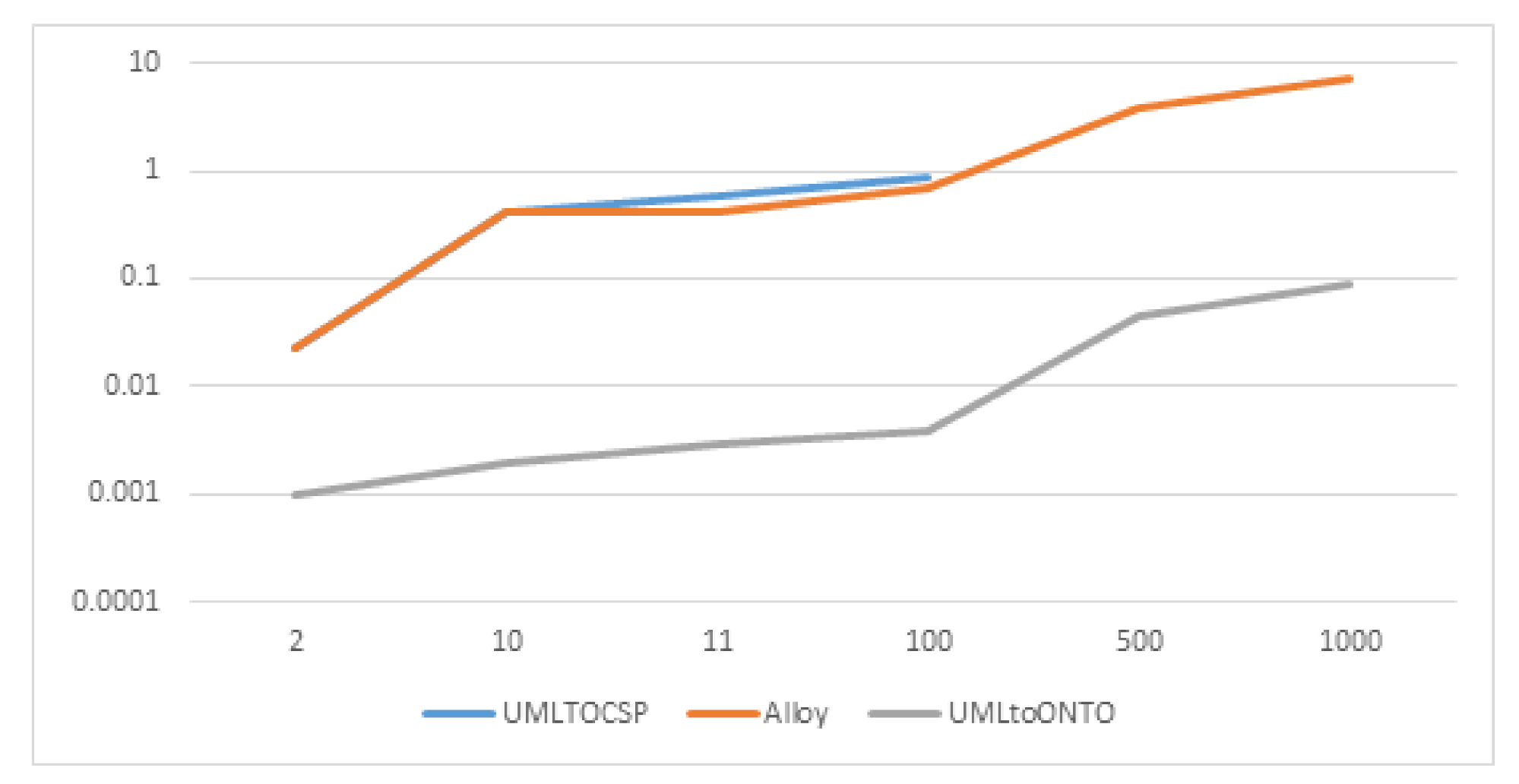
| Model | Classes | Associations | UMLTOCSP | Alloy | UMLtoONTO |
|---|---|---|---|---|---|
| Employee Department | 3 | 5 | 0.032 s | 0.032 s | 0.00099 s |
| Travel Agency | 12 | 12 | 0.51 s | 0.51 s | 0.00210 s |
| Pet Store | 18 | 19 | 0.65 s | 0.631 s | 0.00328 s |
| Programmed 1 | 100 | 100 | 0.89 s | 0.686 s | 0.003963 s |
| Programmed 2 | 500 | 500 | Timeout | 3.890 s | 0.04534 s |
| Programmed 3 | 1000 | 1000 | Timeout | 7.28 s | 0.090366 s |
| Model Name | Classes | Associations | XOR | Case 1 | Case 2 | Verification Time |
|---|---|---|---|---|---|---|
| Project Tasks | 4 | 3 | 1 | ✓ | × | 0.035 |
| Order Management | 6 | 8 | 3 | × | ✓ | 0.103 |
| Meta-model of value Properties Attributes | 4 | 10 | 3 | ✓ | × | 0.080 |
| Restaurant | 8 | 8 | 3 | ✓ | ✓ | 0.100 |
| Programmed 4 | 100 | 200 | 100 | × | ✓ | 0.547 |
Publisher’s Note: MDPI stays neutral with regard to jurisdictional claims in published maps and institutional affiliations. |
© 2022 by the authors. Licensee MDPI, Basel, Switzerland. This article is an open access article distributed under the terms and conditions of the Creative Commons Attribution (CC BY) license (https://creativecommons.org/licenses/by/4.0/).
Share and Cite
Rajab, A.; Hafeez, A.; Shaikh, A.; Alghamdi, A.; Al Reshan, M.S.; Hamdi, M.; Rajab, K. UCLAONT: Ontology-Based UML Class Models Verification Tool. Appl. Sci. 2022, 12, 1397. https://doi.org/10.3390/app12031397
Rajab A, Hafeez A, Shaikh A, Alghamdi A, Al Reshan MS, Hamdi M, Rajab K. UCLAONT: Ontology-Based UML Class Models Verification Tool. Applied Sciences. 2022; 12(3):1397. https://doi.org/10.3390/app12031397
Chicago/Turabian StyleRajab, Adel, Abdul Hafeez, Asadullah Shaikh, Abdullah Alghamdi, Mana Saleh Al Reshan, Mohammed Hamdi, and Khairan Rajab. 2022. "UCLAONT: Ontology-Based UML Class Models Verification Tool" Applied Sciences 12, no. 3: 1397. https://doi.org/10.3390/app12031397
APA StyleRajab, A., Hafeez, A., Shaikh, A., Alghamdi, A., Al Reshan, M. S., Hamdi, M., & Rajab, K. (2022). UCLAONT: Ontology-Based UML Class Models Verification Tool. Applied Sciences, 12(3), 1397. https://doi.org/10.3390/app12031397