1. Introduction
Prosthetic rehabilitation of a dental patient involves the introduction of artificial artifacts in a highly dynamic system. such as the stomatognathic apparatus, becoming an integral part of it or a replacement, both anatomically and functionally. All materials and restoration techniques have limitations and do not have the same characteristics as the natural tooth structure. As such, the clinician must choose the appropriate procedure for each clinical case while simultaneously considering the requests and needs of the patients. Therefore, the dentist will have to choose a solution that can withstand the loads of the occlusal surface of the dental arch in the concerned area, and she/he will try to comply with the aesthetic requirements of the patient. Knowledge of the characteristics of the different solutions is a prerequisite for the satisfaction of these two aspects.
Single-tooth replacement in the posterior zone, when dealing with ideally positioned implants, can be achieved by combining a prefabricated abutment and a crown. Implant restorations are usually directly connected to implants with screws, or they can be cemented to abutments, which are attached to implants with screws [
1].
Resin composite materials (i.e., NCRC), compared to glass-ceramic crowns, are proven to be less abrasive on the opposing dental structure [
2] and offer significant advantages compared to traditional ceramic materials, which are related to their machinability and intra-oral reparability [
3]. From a clinical functional point of view, the use of zirconia, a material with high resiliency, i.e., with an improved capability to absorb energy when it is deformed elastically and to recover its size and shape upon unloading, allows a reduction of the stress transmission to the adjacent bone [
4], thus having a favorable effect on tooth replacement survival after single-implant-supported restorations. The excellent absorption capacity and deformability characteristics of a three-unit bridge manufactured with those veneered using either zirconia or milled fiber-reinforced composite frameworks [
5] or a single crown made with composite CAD-CAM blocks have already been demonstrated in a previous study [
6,
7]. On the other hand, the choice to use a full manufactured zirconia abutment directly screwed onto an implant does not seem to be as good as the choice of a zirconia structure cemented on a titanium core abutment. Indeed, the customized zirconia framework cemented on a titanium abutment represents the right balance between aesthetics and achievable mechanical properties [
8,
9]. One of the main issues related to the connection between the crown and abutments is the shear bond strength. Recent studies found that resin cement systems showed high shear bond strength values when zirconia was resin bonded to either titanium or the corresponding zirconia substrate [
10]. Priming after sandblasting or hydrofluoric acid etching could be effective at increasing the bond strength of CAD/CAM blocks [
11]. Some cement systems with functional monomers had significantly higher bond strengths [
12]. In real crown abutment assemblies, it is very difficult to control the cement thickness, which influences the shear in the bonded joint, and consequently, in this study, investigation of the whole abutment-cement-crown system is preferred, as it is more representative of an in vivo case.
Regarding the mechanical testing of dental implants, several studies were conducted to assess the performance of the connection between the crown and the abutment, and, in general, the implants. To simulate in vivo working conditions, the fatigue behavior of dental implants was also investigated in [
13,
14,
15,
16,
17,
18,
19,
20]. Alemayehu and Jeng [
13] performed numerical finite element analyses simulating the static, quasi-static, and dynamic response of several implants, highlighting the importance of dynamic tests since the application of dynamic loading can increase the stress of dental implants and cortical bone by as much as 30–60% if compared to static loading. Jang et al. [
14] investigated the strength of a lithium disilicate-reinforced liner used for the bonding between a zirconia abutment and a glass-ceramic final prosthesis. They also compared the bond strength of the liner solution with a more common cement-bonding solution, obtaining a significantly higher bond strength and fracture resistance. Taha et al. [
15] evaluated the force absorption capacity of implant-supported restorations using different CAD-CAM materials for the fabrication of crowns and customized abutments. They tested four groups of crowns and abutments and the results showed that combining rigid crown materials with less rigid abutments might enhance their force absorption capacity. At the same time, they stressed the fact that a stiff substructure might be mandatory when using less rigid crown materials for preserving the force absorption behavior.
The aim of the present study was to assess in vitro the static strength, fatigue resistance, and failure mode of a CAD-CAM resin composite material (nano ceramic resin, NCR), bonded to a non-retentive custom zirconia implant abutment or directly to a standard titanium abutment proposed for aesthetic solutions.
This study hypothesized that the abutment design would influence the fatigue resistance and failure mode of the assembly.
2. Materials and Methods
Thirty implants with an internal conical tapered configuration with a 4 mm diameter and 11.5 mm length (Cyroth—AoN Implants) were embedded in acrylic resin (Palapress; Heraeus Kulzer) to provide slight movability of the tooth, simulating natural tooth mobility during chewing simulation and fracture resistance testing [
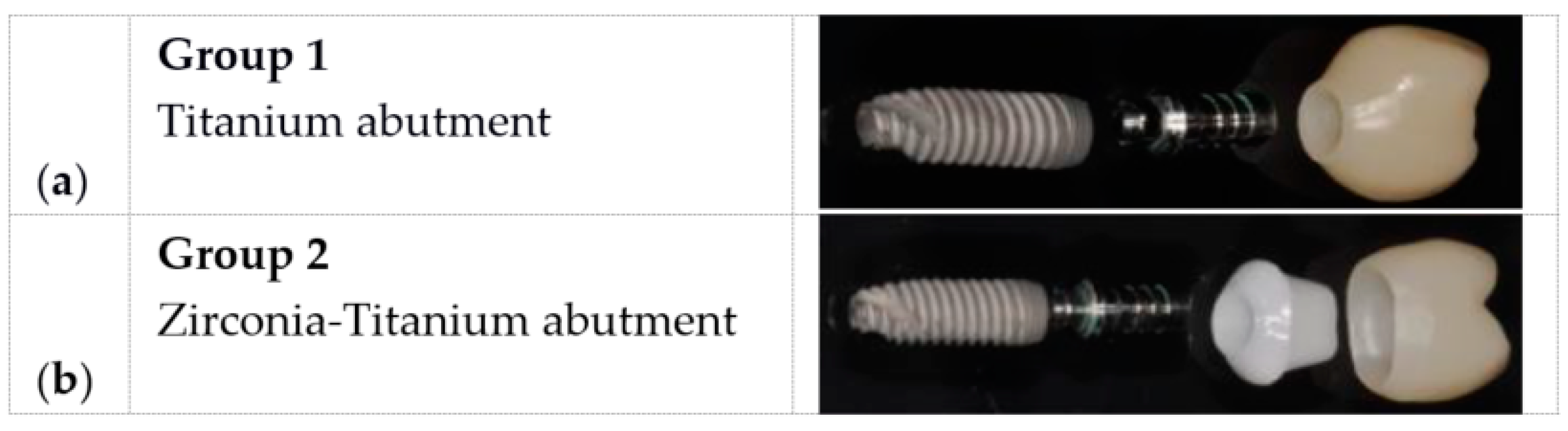
1]. The resin supports were drilled by burs supplied by the manufacturer and then tapped to allow the insertion of the implant using a wrench limited to 60 Ncm torque, at the end of the screwing only. Each implant received a standard titanium abutment (Moncone per Zirconia—AoN Implant), fastened with 25 Ncm torque applied to the abutment screw, and then sandblasted with aluminum oxide particles with an average diameter of 30 μm (Cojet sand, 3M Espe) (
Figure 1).
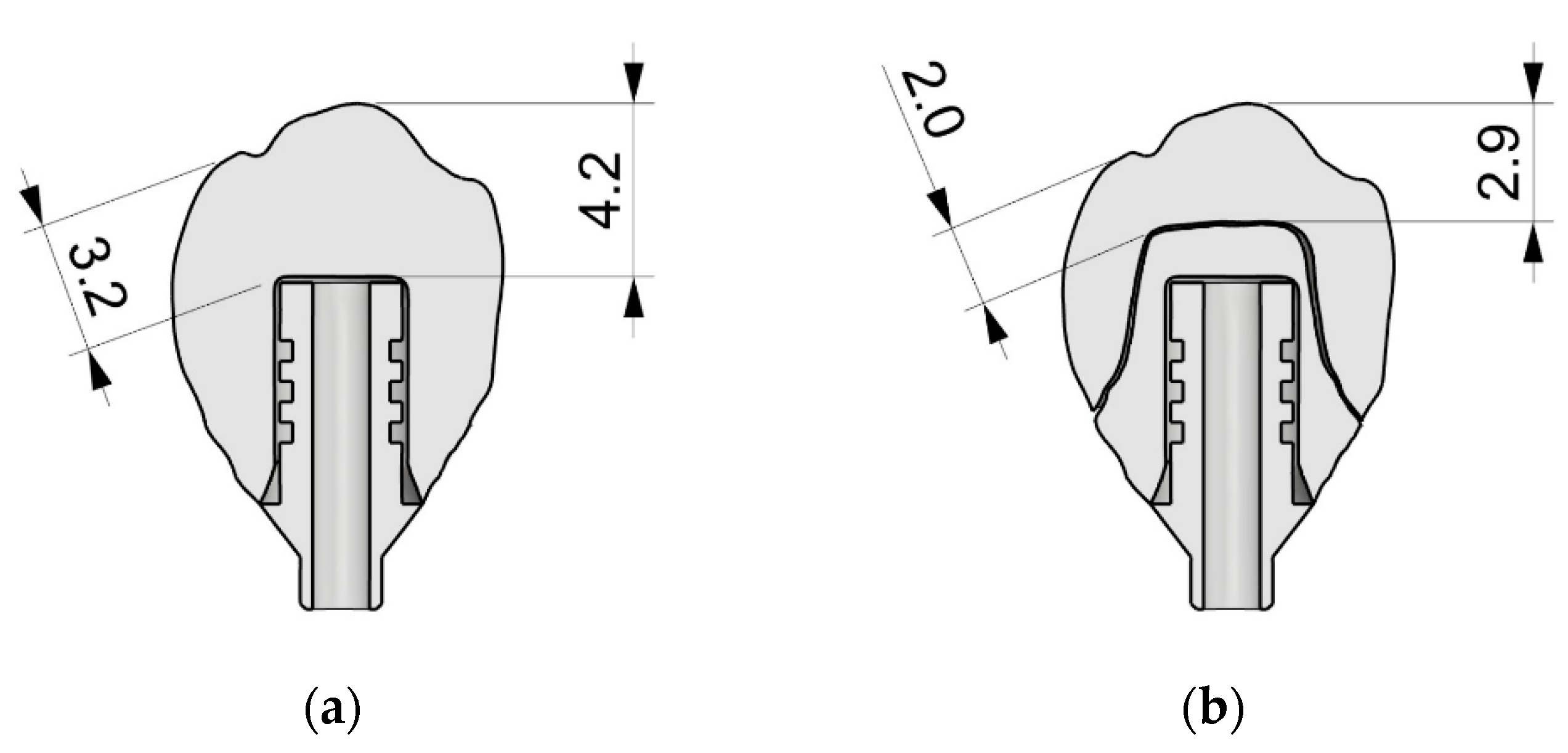
A right maxillary second pre-molar was designed in a CAD environment (Lava Design 7 3M Espe) with two different configurations (see
Figure 2). One type was designed for fitting to a customized zirconia abutment whereas the second type was designed for fitting to a standard titanium abutment, with the size and shape of the tooth remaining unchanged.
From this CAD design, 30 crowns were milled (Trentotech—3M Espe authorized milling center, TN Italy) in a new resin composite material (Lava Ultimate 3M Espe), 15 for each type of design crown fitting configuration (
Figure 3).
In this way, two experimental groups were created. In group 1, 15 Ultimate Lava nano ceramic resin crowns were cemented directly to a titanium abutment that was previously screwed into the fixture and sandblasted with aluminum dioxide powder (
Figure 4).
Each crown and titanium abutment were coated with Scotchbond Universal adhesive (3M Espe) and then RelyX Ultimate (3M Espe) was placed directly on the crown for cementation. After removing the excess cement, photopolymerization was achieved using an LED curing light for 40 s (Valo Led Ultradent), maintaining a manual pressure on the parts. Group 2 consisted of 15 Lava Ultimate nano ceramic resin crowns, cemented on zirconia abutments and screwed to the fixture, and embedded in the resin supports as described above. For this group, a master custom abutment was made by simulating the natural emergence profile of a right maxillary pre-molar. The master abutment was optically scanned and then milled in zirconia dioxide ceramic (Lava™ Zirconia—3M Espe—Trentotech, 3M Espe authorized milling center, TN, Italy) (see
Figure 4). The internal surfaces of the Lava Ultimate crowns were sandblasted with aluminum oxide (Cojet sand, 3M Espe) and the same treatment, both inside and outside, was used for the zirconia abutments that had two distinct adhesive interfaces.
First, the zirconia and titanium abutments were cemented together, carefully following the manufacturer’s instructions. Before cementation, a specific primer (Relix Ceramic Primer, 3M Espe) was applied on both bonding surfaces and then the two abutments were cemented (Relyx Unicem, 3M Espe). After removing the excess cement, and maintaining pressure, they were light cured for 40 s around the finishing line (Valo Led-Ultradent).
The second step cemented the Lava Ultimate crowns to the zirconia abutments. After brushing a thin coat of Scotchbond Universal adhesive (3M Espe) on both adhesive interfaces, without curing the layer, the nano ceramic resin crowns were cemented to the zirconia abutments using Relix Ultimate (3M Espe). During the cementation, pressure was maintained on the structure and the samples were light cured for 40 s (Valo Led-Ultradent). Excess cement resin was removed before photopolymerization by means of a micro-brush.
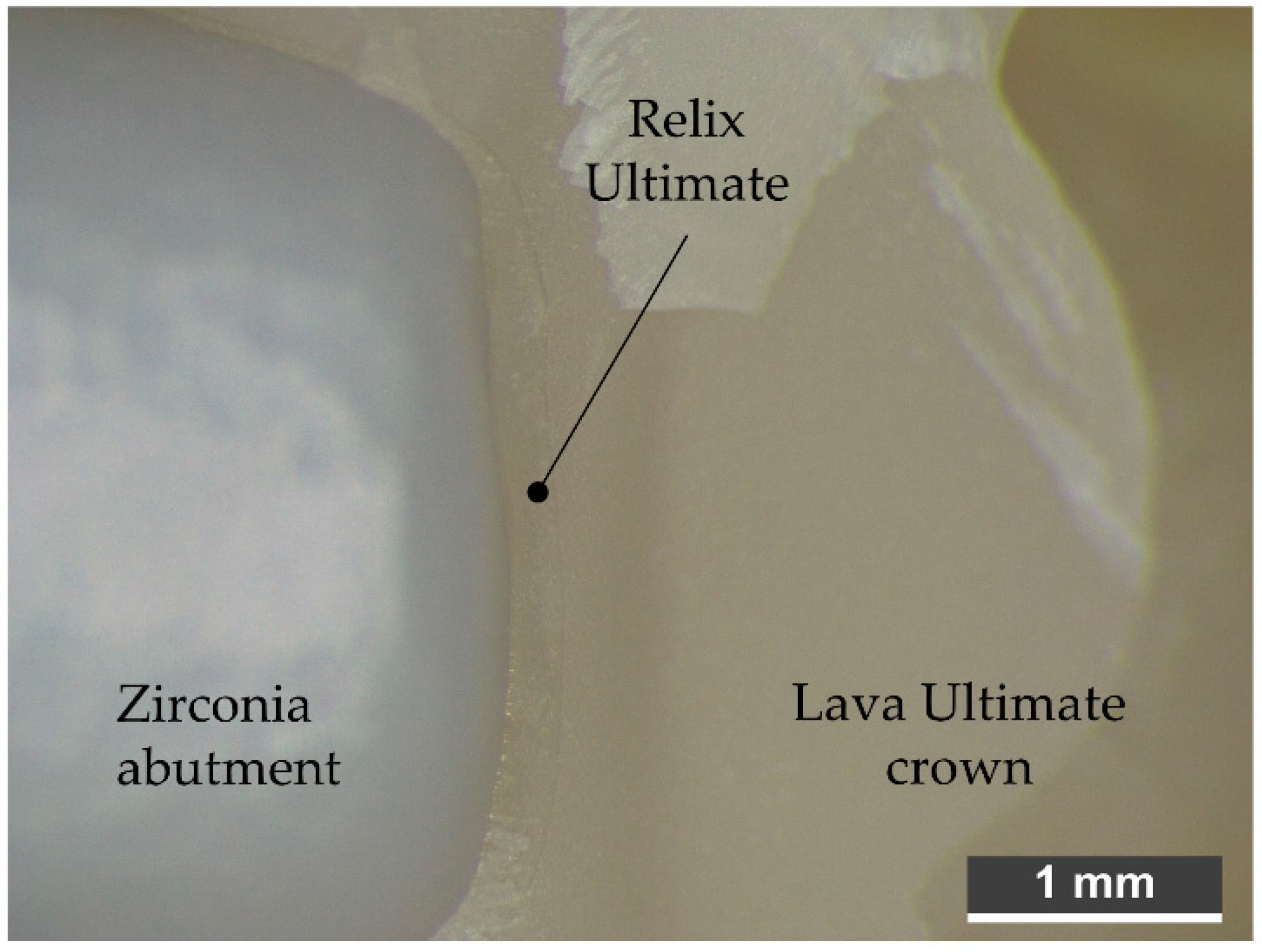
Figure 5 shows the result of the procedure, in which the thin layer of Relix Ultimate material is visible between the crown and the zirconia abutment.
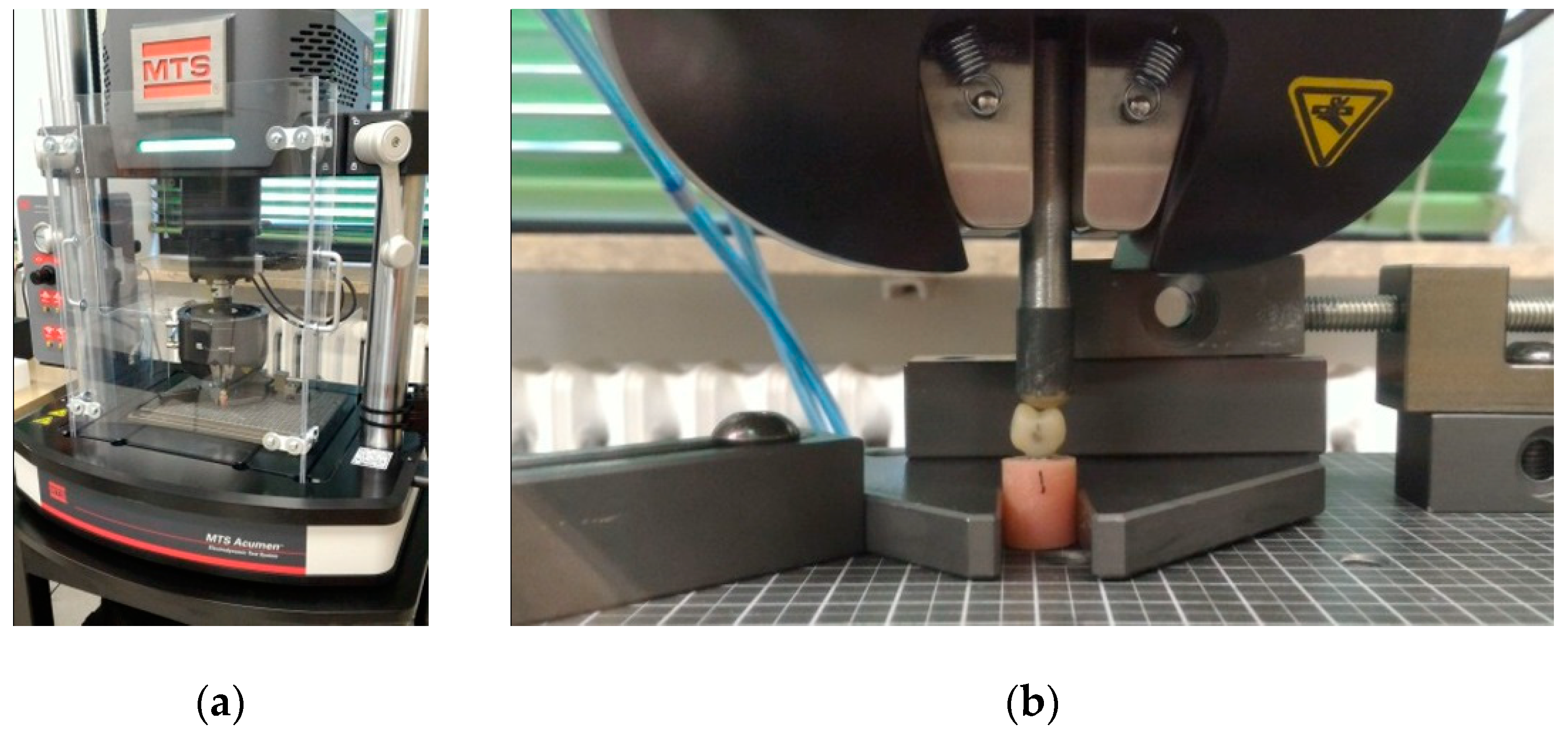
In order to test the characteristics of the resistance to static and dynamic loads an MTS Acumen 3 Electrodynamic Test System testing machine equipped with a 3 kN load cell was used. The load was applied by means of a steel cylinder (Ø7 mm) with a composite (Filtek Supreme XTE 3M Espe) hemispherical end until failure of the sample. The cylinder was replaced for each sample. The sample was supported by grippers, as shown in
Figure 6b, and aligned to ensure the axis of the resin cylinder and the axis of the loading steel cylinder were consistent, guaranteeing repeatability and equal testing conditions throughout the test campaign. Before testing the specimens, the system was dynamically calibrated in the range 0 to 20 Hz by the internal utility of the machine control software MTS TestSuite Multipurpose Elite.
For each group, a compressive test was performed on 3 samples and a sinusoidal cycling loading test was performed on 12 specimens.
The fatigue test was inspired by the protocol adopted by Pascal Magne [
6]. In this study, the cyclic load was carried out at a constant frequency (5 Hz), using a stair load history: 5000 cycles in the range 0–50 N and 25,000 cycles in the ranges 50–450 N, 50–650 N, 50–850 N, 50–1050 N, 50–1250 N, and 50–1450 N, (total 155,000 cycles). The first part of the test simulates the masticatory force in the posterior areas while the second part simulates parafunctional events, such as bruxism or exceptional events related to masticatory trauma.
3. Results
As reported in
Table 1, regarding the static test, in group 1, the failure load was 2227 N (SD 58.2 N). The samples of group 2 failed at 2490 N (SD 95.8 N).
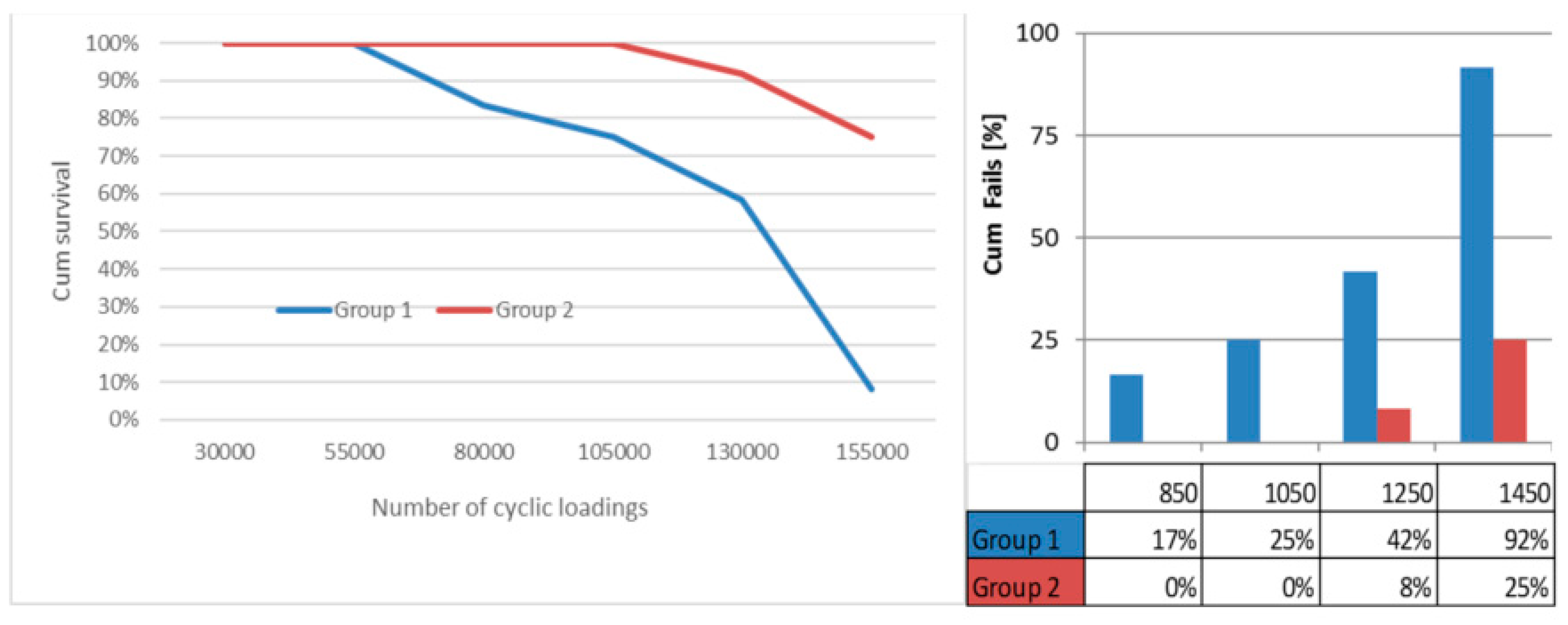
The fatigue test, as reported in
Table 2, shows that all samples withstood pressure above the average chewing force of 130 N [
21]. Only one sample of group 1 (8.3%) survived the entire test, with group 1 samples failing at an average of 130,000 cycles at 1053 N (SD 162.5 N). In group 2, 9 samples (75%) finished the test at 155,000 load cycles without failure (
Figure 7).
Moreover, it can be noted that the fracture mode differs between the two different groups: in group 1, all samples showed complete destruction of the crown with total debonding of the NCR material from the titanium abutment (
Figure 8a). Conversely, all customized abutments’ and crowns’ fracturing was partial in all cases and did not affect the zirconia abutment (
Figure 8b).
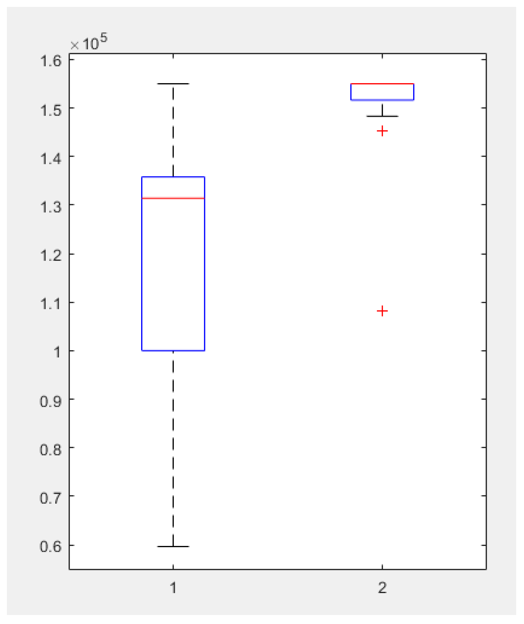
The means, standard deviations, and minimum and maximum fracture loads for the two groups from the static test are listed in
Table 1. The samples in group 2 presented higher failure (2490 N) loads when compared to the samples in group 1 (2227 N).
Descriptive statistics and the one-way ANOVA test (significance of 0.05) were used to determine the effect of the failure loads among the two groups (
Figure 9). To test whether the fatigue response of the crown was significantly affected by the geometry of the two proposed abutments, one-way analysis of variance was performed for both groups on the number of survival samples at varying load values. The validity of the test was tested by Leven’s test, ensuring the assumption of homogeneity of variance (
p-value 0.008).
The p-value for the F-statistic of the ANOVA test was 0.0459 for the survival load values and 0.0034 for the survival cyclic numbers (smaller than the significance level of 0.05), confirming that the fatigue resistance of the crowns with different abutment architectures is not the same.
4. Discussion
The aim of this study was to assess the static and fatigue resistance of Lava Ultimate crowns bonded directly to a titanium abutment (group 1) or bonded to a custom zirconia framework and then cemented to a standardized titanium abutment (group 2).
The composite crown directly bonded to a titanium abutment failed first in the static test compared to the multilayer solutions, and in the fatigue test, it systematically failed before ending all the cycles’ load, thus suggesting that the customized zirconia framework (size and shape) significantly influences both the fatigue and static resistance.
In group 1, the static load results showed a mean fracture resistance 200 N lower than in group 2. Moreover, the type of fracture observed in group 1 was always complete and left the titanium abutment completely exposed.
Instead, in group 2, the fracture has occurred with complete debonding of just one portion of the crown at the point of load application. A large part of the composite crown, however, remained perfectly bonded to the zirconia abutment.
The differing response shown in the dynamic testing between the two sets of samples can be explained by the geometric morphology of the two abutment designs. In group 1, the applied forces are distributed fully on the abutment and discharged vertically on the implant, delaying the creation and spread of fractures due to the shape of the zirconia tailored abutment, which is free of sharp edges.
In group 2, the forces applied to the occlusal surface are concentrated on the titanium abutment roof, acting as a wedge against the internal composite crown. The load forces are not discharged in a uniform manner on the titanium abutment, resulting, as discussed in [
22], in mechanical conditions (i.e., sharp edges/fillets) that allow the propagation of cracks, which increase during load cycles, until sample failure. Therefore, the shape of the titanium abutment determines premature failure of the samples rather than the material itself.
The values in the static test recorded in our study are higher than those reported in a similar test, which investigated prosthetic restorations of premolars. In this study, the fracture resistance of monolithic lithium disilicate (1900 N) and metal ceramic [
23] (1800 N) and zirconia veneered with porcelain was evaluated [
24] (1700 N).
From the point of view of the dynamic load, one study found that the breaking value for a lithium disilicate premolar prosthesis was 1200 N to 800 K cycles [
25]. Another paper [
26] am average value of failure of 1280 N at 160 K cycles in 70% of samples made of a CAD-CAM ceramic material (paradigm C), and tested with a protocol similar to that used in this study. In the same article, the author tested identical samples manufactured in a CAD-CAM composite material (MZ 100), detecting a 100% survival rate at 1400 N for 180 K cycles.
It is obvious that these values are strongly influenced by the morphology of the sample. In fact, incisors tested in another study [
27] reached values of 240 (paradigm C) or 280 N (MZ 100) at about 120 K cycles in both prosthetic solutions. Another study [
2] compared CAD-CAM crowns made with ceramic material (MKII) and composite (MZ 100) on extracted molars using a loading protocol similar to that used in previous studies and measured a fatigue fracture resistance of 1147 N and survival of 0% in the first group and a survival of 73% of the samples in the second group.
An unsolved problem is the use of coupling agent, including both its type and resin–implant connection, and this is worthy of a deeper analysis to provide a more comprehensive understanding of the mechanical relations of the implants in the mouth during their lifecycle.
In vitro study is important to achieving mechanical quality of materials, but it is clear that only long-term clinical trials will provide evidence of in vivo success of materials and production techniques.
5. Conclusions
Within the limitations of this in vitro study, the following conclusions were made: in both tests of static and fatigue resistance, the individualization of the zirconia abutment allowed a nano ceramic veneered crown to be obtained that was mechanically superior to the cheaper solutions, which provides a CAD-CAM composite crown cemented directly to a standardized titanium abutment. The static and dynamic tests showed results in line with data reported in other similar works published in the scientific literature.
All the samples made with the zirconia framework coated with nano ceramic composite material finished the fatigue test protocol without failure.
None of the samples manufactured entirely with the composite material and cemented to a titanium abutment ended the fatigue stress test. In fact, all the samples failed at a load that was approximately half the value recorded during the static resistance test.
These findings support the hypothesis that the engineering of the size and shape of the titanium abutment can improve the mechanical properties of the nano ceramic resin crown (NCRC), resulting in a less expensive fatigue-resistant solution.


 ,
, 


