Article

Experimental Investigation and Exergy Analysis of Dehumidification Performances for a Cascaded Phase Change Heat Storage Dehumidifier

School of Power and Energy, Northwestern Polytechnical University, Xi’an 710072, China
*
Author to whom correspondence should be addressed.
Appl. Sci. 2022, 12(3), 1303; https://doi.org/10.3390/app12031303
Submission received: 4 January 2022 / Revised: 24 January 2022 / Accepted: 24 January 2022 / Published: 26 January 2022
(This article belongs to the Special Issue Advances in Thermal Energy Storage Technology)

Abstract

:
In the humidification and dehumidification solar desalination system, the recovery of vapor condensation latent heat is the key problem. Using a cascaded phase change heat storage method to recover vapor condensation latent heat can improve the phase change heat storage rate and the water production performance of dehumidifier. The exergy analysis and experimental methods are used to study the cascaded phase change storage dehumidifier. The results show that the more stages of phase change materials in the cascaded phase change heat storage device, the greater the exergy efficiency will be. The heat transfer performance of phase change materials increases with the increase of hot and wet air temperature and flow at the inlet of the dehumidifier. The exergy efficiency and gain output ratio of three-stage phase change heat storage are higher than that of the single-stage. The three-stage one is recommended. If the heat recovered by the cascaded phase change heat storage device is supplied to the passive humidification dehumidification desalinator for secondary water output, the water output and gain output ratio will increase by 25% and the water production cost will be reduced by 20%. The results can provide a basis for the design and application of a cascaded phase change heat storage dehumidifier.

1. Introduction

The application of phase change heat storage technology can effectively solve the contradiction of mismatch between time and space in solar thermal energy and has broad application prospects in the utilization of solar energy and industrial waste heat resources [1].
Solid–liquid phase change heat storage has the advantages of high heat storage density, little temperature change and stable chemical properties, but most phase change materials (PCMs) have low thermal conductivity and a slow heat storage and release rate, which cannot meet the requirements of engineering application [1]. Therefore, strengthening the heat transfer of PCM and improving their heat storage and heat release rate are very important to expand the application of phase change heat storage [2].
There are two main methods to enhance the heat transfer rate of PCM at present. One is to add metal fins to the heat exchange tube; the other is to add higher thermal conductivity materials in PCM, such as adding metal foam or carbon nanofibers. Although the above methods can increase the heat transfer rate of PCM, they also lead to the reduction of the filling rate and heat storage density of PCM, the incompatibility between PCM and metal materials or the desorption of carbon-based materials after multiple phase transformations.
Cascaded phase change heat storage is achieved by arranging several different PCM according to their phase transition temperatures, reducing, in turn, in the flow direction of the thermal fluid, in order to reduce the difference between the thermal fluid temperature and the phase change temperature of PCM at every stage [3,4]; thus, PCM can reach the phase change temperature faster for heat storage [5].
Farid et al. [6] first proposed the theoretical model of a cascaded phase change heat storage system in 1986 and verified that cascaded phase change heat storage can improve the efficiency of the system by the theoretical analysis method. Xu et al. [7] studied the exergy flow and exergy efficiency in the heat transfer process by exergy analysis, which provided theoretical guidance for the cascaded heat storage system. Li et al. [8] studied the application of entropy in the phase change process and concluded that the multi-stage utilization of PCMs can make the phase change process faster.
Khor et al. [9] studied the optimization of the cascaded thermal energy storage system; the PCMs in the form of a packed bed were used to achieve a high storage capacity, and optimized the storage capacity in each temperature region to achieve a high storage efficiency. Shamsi et al. [10] used a multilayer phase change heat storage system and modeled and optimized it. Zhao et al. [11] established a latent heat storage system composed of three kinds of PCM. By studying the heat storage process of the system, it was found that increasing the number of PCM stages can improve the energy storage efficiency. Huang et al. [12] proposed a heat storage system with cascaded PCM, studied the optimal parameters of PCM through simulation and obtained that the phase change temperature range was 320.65~330.65 K, and the optimum volume ratio of the PCM unit to water tank was 0.67. Hassanpour et al. [13] designed a two-phase closed thermosyphon, which can extract heat energy through a cascaded PCM heat exchanger, and a thermodynamic analysis showed that cascaded phase change heat storage is an effective method to reduce exergy loss. Cheng et al. [14] proposed a device with cascaded packed bed cold heat energy storage using multiple PCMs. During the charging process, the thermal performance was close to optimal when using 3~5-stage PCMs, and its charging time was reduced by 15.1%. Majumdar et al. [15] analyzed the effects of different diameter spherical capsules with different melting temperature PCMs filled in the storage tank on the thermal storage performance of multilayer packed bed latent heat thermal energy storage (PBLTS); the results showed that, during the heat charging and heat release process of PBLTS, the arrangement of capsules with different diameters had a significant impact on the heat storage performance of PBLTS. Wang [16] studied the change law and temperature distribution law of the solid–liquid interface, which is the surface of combined PCM of the device with phase change heat storage; the results showed that, compared with the single-stage layout modes, the combined PCM can enhance the melting uniformity of the device with phase change heat storage, improve the phase change rate, reduce the temperature gradient and enhance the stability of the system.
Zhu et al. [17] filled the packed bed with variable-diameter particles, and the thermal performances of three-stage packed beds were numerically simulated; the research indicated that, when the particle diameters of the top, middle and bottom layers were 0.025, 0.0325 and 0.0325m, respectively, the exergy efficiency of the cascaded packed bed came to be the highest. Riahi et al. [18] compared PCM with a graphite phase change heat storage system; the results showed that the cascaded indirect systems of graphite PCMs can improve the system efficiency. Mahdiet al. [19] studied a cascaded PCM consisting of a 5% volume fraction and average porosity of 0.95 nanoparticles and metal foam and applied it to the heat transfer process of a shell and tube energy storage system. The results showed that, compared to the module of a single PCM with no nanoparticles or cascaded foam, the full solidification time-saving of multiple PCMs was up to 94%. Mawire et al. [20] experimentally compared single-stage and two-stage PCM thermal energy storage systems based on eutectic solder (Sn63/Pb37) metallic PCMs during their charging and discharging cycles. It was found that the system with two-stage PCM thermal energy storage had a higher exergy efficiency.
Suresh et al. [21] studied the effect of different volume fractions of PCM in a storage tank on the thermal storage performance of a thermal energy storage system during charging and discharging, and the results showed that the higher volume fractions of PCM had greater energy storage, and the thermal energy storage systems with volume fractions of 80% and 60% had better heat storage performances than those with volume fractions of 40% and 20%. Cheng et al. [22] analyzed the heat transfer performance and the cold storage performance of the devices with phase change heat storage, and the results showed that heat transfer had the best performance when three types of PCMs, with phase change temperatures of 285.45 K, 286.15 K and 286.45 K, were combined with a ratio of 1:1:1. Under these conditions, the exergy efficiency was up to 72.2%. Compared with the device with a single phase change heat storage, with a phase change temperature of 286.15 K, the exergy efficiency and cold storage rate were increased by 1.2% and 1.7%, respectively. Zheng et al. [23] used a shell and tube latent heat storage unit to study the performance enhancement of the melting characteristics, and the effects of the rates of the porosity and ratio of PCMs of the first stage to those of the second stage on the melting rate were investigated. Ahmed et al. [24] introduced a new type of combined sensible–latent heat energy storage structure into a tank-type thermocline thermal energy storage (TES), and three types of PCMs were stacked along the height side according to different volume fractions; the results indicated that the arrangements of TES with volume fraction arrangements of 40% for PCM1, 20% for PCM2 and 40% for PCM3 had the best performances.
Elfeky et al. [25] studied the phase change temperature of multilayer PCMs in thermal storage tanks of solar power plants; the results showed that the phase change temperature of PCM in the first layer was 328.55 K lower than the temperature of the inlet thermal fluid in the heat storage process, and the phase change temperature of PCM in the third layer was 356.25 K higher than the outlet temperature; the multilayered phase change materials became the most uniform temperature distribution. Tehrani et al. [26] proposed a joint system of cascaded PCMs and multilayered solid PCMs, which was applied to the thermal energy storage of a concentrated solar power plant. The results indicated that a design configuration that was filled with a high melting point PCM in the top 25% of the heat storage tank, sensible concrete in the middle 50% and a low melting point PCM in the bottom 25% of the tank had the best performance among all the design alternatives studied. Mao et al. [27] analyzed the thermal performance of three different PCM capsules in a packed bed solar energy storage system, and the research indicated that the storage capacity and utilization rate of three-stage PCM energy storage tanks are higher than others.
To sum up, the cascaded phase change heat storage method has been studied and applied in many fields. However, up to now, in the humidification and dehumidification solar desalination system, the research on recovering the latent heat of vapor condensation in the dehumidification process by means of cascaded phase change heat storage has not been reported. The recovery of vapor condensation latent heat is the key problem in humidification and dehumidification solar desalination technology. The use of cascaded phase change heat storage is conducive to improving the uniformity of phase change and the phase change heat storage rate so as to improve the utilization rate of phase change materials and the water production performance of a dehumidifier. In this paper, the cascaded phase change heat storage dehumidifier in the humidification and dehumidification solar seawater desalination system is the research object, with an exergy analysis and comparison on the exergy utilization rate for the dehumidifier with different phase change material stages to determine the applicable number of stages. Through experiments, the effects of the hot and wet air temperature and the volume flow at the inlet of a dehumidifier on the melting process of phase change materials and the effects of the number of phase change material stages on the water output, the gain output ratio and the water production cost of a dehumidifier will be studied in order to determine the appropriate operating parameters and the number of phase change material stages so as to achieve the goal of improving the exergy efficiency, water output and gain output ratio of the dehumidifier and reducing its water production costs.

2. Exergy Analysis of Cascaded Phase Change Heat Storage

2.1. Analysis of Optimum Phase Change Temperature at all Stages

The temperature variation of fluid in the heat storage process of cascaded PCMs is shown in Figure 1.
Tin and Tout are the thermal fluid temperature at the inlet and outlet of the cascaded phase change heat storage dehumidifier, K, Tp,i is the phase change temperature of stage i of the PCMs, K and n is the total number of stages.
For the convenience of theoretical calculation and analysis, the sensible heat and heat loss in the process of heat storage are ignored. The exergy of the thermal fluid in the cascaded phase change heat storage process corresponding to Figure 1 can be expressed as [28]:
E x = m ˙ c P T in T p , 1 Δ T 1 1 T 0 T p , 1 + i = 2 n m ˙ c P T p , i 1 Δ T i 1 T p , i + Δ T i 1 T 0 T p , i
where m ˙ is the mass flow of the thermal fluid, kg/s; cp is the specific heat capacity at constant pressure, kJ/(kg·K); T0 is the ambient temperature, K and ∆Ti is the difference between the thermal fluid temperature at the outlet of stage i and the phase change temperature of PCMs, K.
Assuming the ∆Ti of each stage is equal, and ∆Ti = ∆T, when the number of total PCM stages is n, by deriving the phase change temperatures Tp,i at all stages of Formula (1), it can be obtained that, when the exergy is the maximum, the expression of the optimal phase change temperature Topt,n,i (K) of the phase change material at stage i is [28]:
T opt , n , i = T in Δ T n i + 1 T 0 i n + 1   ( I = 1 ,   2 ,   3 ,   . . . . . . ,   n )
Table 1 shows that, when the ambient temperature T0 = 298.15 K, the temperature of the hot and wet fluid entering the cascaded phase change heat storage device Tin is 328.15 K, taken as Δ T = 0, 5 and 10 K, respectively, and the number of phase change material stages n is 1, 2, 3 and 4, respectively, and the optimal phase change temperatures at all stages of the cascaded phase change heat storage device are Topt,n,i.
It can be seen from Table 1 that, when n and ∆T are constant, with the increase of i, Topt,n,i decreases; under the same n and i, the larger ∆T is, the smaller Topt,n,i is; when i and ∆T are constant, the larger n is, the larger Topt,n,i is.

2.2. Analysis of Exergy Efficiency of Thermal Fluid

In the ideal case, the exergy completely converted by the heat flow of the thermal fluid in the cascaded phase change heat storage device can be expressed as [28]:
E x max = T 0 T in m ˙ c P 1 T 0 T d T = m ˙ c P T in T 0 T T in T 0 T 0 L n T in / T 0
The ratio of the exergy Ex of the thermal fluid after heat exchange by the device to the exergy Exmax of the complete conversion of the heat flow is defined as the exergy efficiency, which is expressed as [28]:
η n = E x E x max = T in T opt , n , 1 Δ T 1 1 T 0 T opt , n , 1 T in T 0 T 0 Ln T in / T 0 + i = 2 n T opt , n , i 1 Δ T i 1 T opt , n , i + Δ T i 1 T 0 T opt , n , i T in T 0 T 0 Ln T in / T 0
When T0 = 298.15 K and Tin = 328.15 K, the difference between the air fluid temperature at the outlet of the dehumidifier and the phase change temperature of the PCMs in each stage ∆T is 0, 5 and 10 K, respectively, and the stage number of PCMs is taken as n = 1, 2, 3 and 4 separately; the exergy efficiency of the thermal fluid η n is calculated and listed in Figure 2.
It can be seen from Figure 2 that, with the number of PCM stages increasing, the exergy efficiency of the thermal fluid increases significantly; however, the relationship between them is not linear. When ∆T is 5 K, and n is equal to 1 and 4, respectively, the exergy efficiency of the phase change heat storage η n is 35.6% and 56.4%, respectively. This means the exergy efficiency can be significantly improved when PCMs are arranged in cascades, and the η n has nothing to do with the physical properties of PCMs.
When n is constant, it can be found that, with the increase of ∆T, η n becomes lower. Considering that the heat transfer process needs a certain temperature difference as the heat transfer driving force, it is recommended to use Δ T = (3~5) K in the actual device design.

3. Cascaded Phase Change Heat Storage Dehumidifier and Its Experimental System

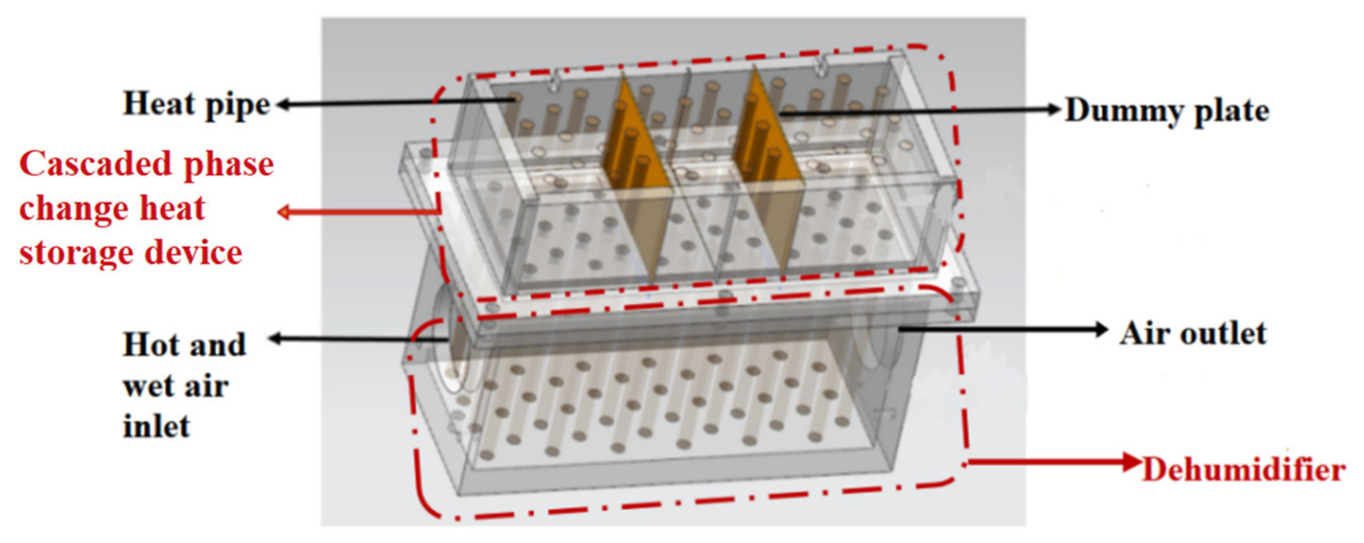
3.1. Structure of Cascaded Phase Change Heat Storage Dehumidifier

The structure of the cascaded phase change heat storage dehumidifier for the experiments is shown in Figure 3. It consists of a cascaded phase change heat storage device and dehumidifier. The phase change heat storage device is separated by a dummy plate, and the paraffins with different phase change temperatures are filled in the storage. The hot and wet air enters the dehumidifier and conducts heat transfer with the heat pipes. In order to accelerate the condensation rate of the vapor in the hot and wet air, finned heat pipes are used to enhance the heat transfer on the hot and wet air side.

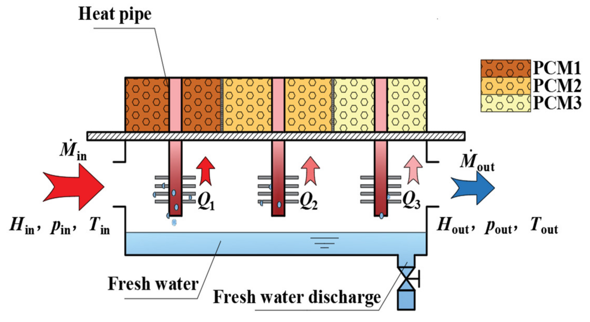
3.2. Working Principle of Cascaded Phase Change Heat Storage Dehumidifier

The working principle of the cascaded phase change heat storage dehumidifier is shown in Figure 4. Paraffin is a commonly used low-temperature phase change material with a relatively high latent heat of the phase change, and the phase change temperature of paraffin is around 323.15 K. During the experiments, the temperature of the hot and wet air at the inlet of the dehumidifier is 333.15~343.15 K. Within this temperature range, the paraffin can just be used for storing the latent heat of the water vapor. Therefore, paraffins with phase transition temperatures of 325.15 K, 323.15 K and 321.15 K were selected as the cascaded phase change materials, and they are represented by PCM1, PCM2 and PCM3, respectively. The hot and wet air flows from left to right at the bottom of the dehumidifier to exchange heat with the finned heat pipe for cooling. Part of the water vapor in the hot and wet air condenses into fresh water and falls to the bottom of the dehumidifier. The condensation latent heat of the water vapor is successively transferred to PCM1, PCM2 and PCM3 at the upper part of the heat pipe, which melts PCM, and the heat is stored by PCMs.
In Figure 4, for the dehumidifier, M · in and M · out are the air mass flow at the inlet and outlet, kg/s; H in and H out are the total enthalpy of air at the inlet and outlet, kW; pin and pout are the air pressure at the inlet and outlet, Pa and Tin and Tout are the air temperatures at the inlet and outlet, K.
Figure 5 is a schematic diagram of the three-phase change materials PCM1, PCM2 and PCM3 in different arrangements. Among them, CASE1~CASE3 are the single-stage layouts, and CASE4 is the three-stage layout.

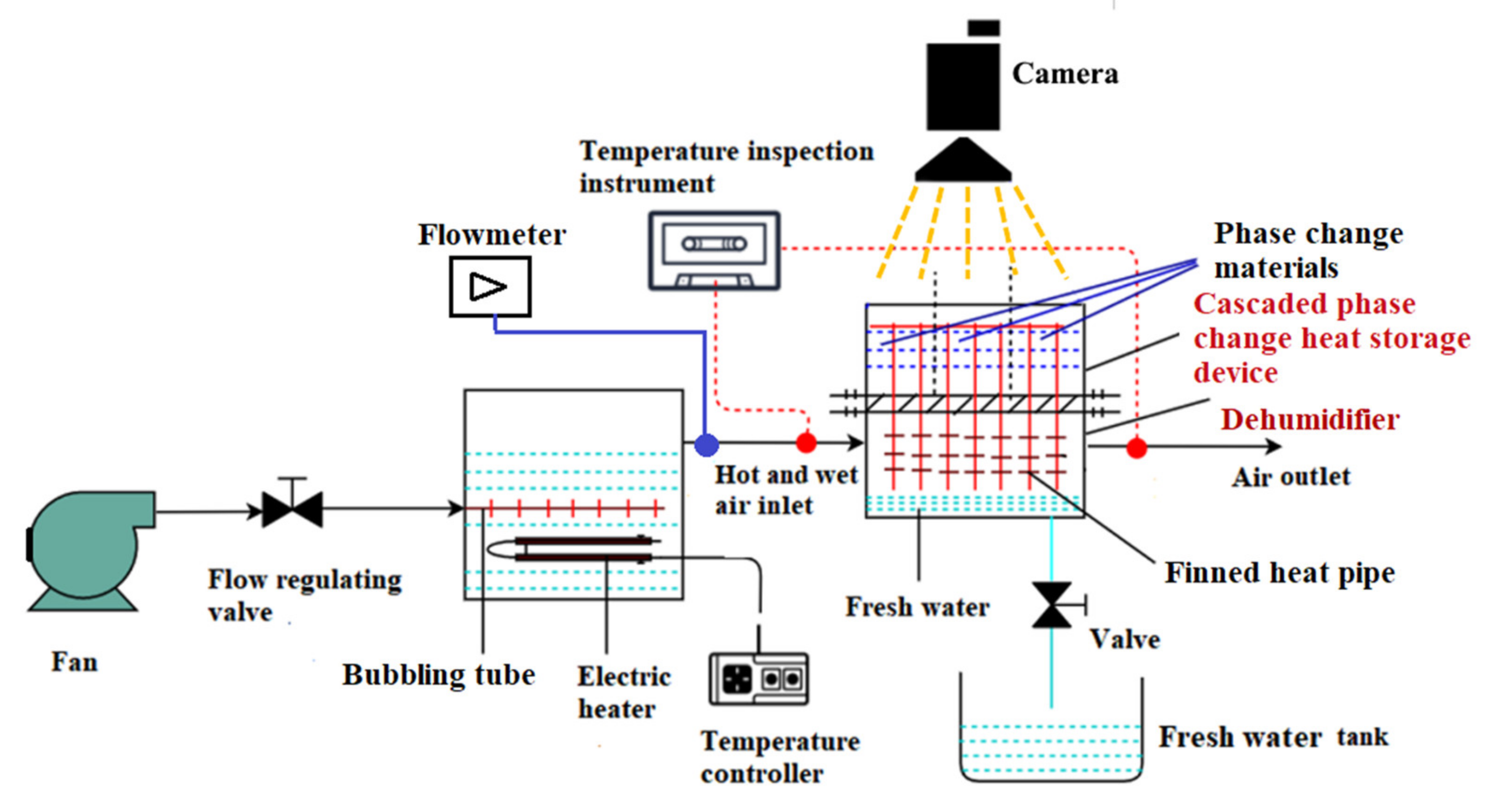
3.3. Experimental System

The experimental system of the cascaded phase change heat storage dehumidifier is shown in Figure 6. The air flows into the system by the fan, and the water temperature is controlled by the temperature controller to control the temperature of the hot and wet air at the inlet of the dehumidifier. A K-type thermocouple is used to monitor the temperature of the hot and wet air at the inlet and the air at the outlet of dehumidifier; the flowmeter is used to monitor the volume flow of the hot and wet air at the inlet of the dehumidifier, and the heat transfer law of the PCMs on the upper surface of the phase change heat storage is studied combined with a camera. The water production cost and gain output ratio of the dehumidifier is calculated based on the measured water output.

3.4. Definition of Experimental Performance Parameters

The indexes commonly used to evaluate the performance of the dehumidifier system are the gain output ratio (GOR) and water production cost (WPC). The definition of the GOR is the ratio of the product of the water output M and water evaporation latent heat γ in a certain period to the power consumed E at the same time, and the GOR is expressed as [29]:
GOR = M γ 3600 E = M γ 3600 ( P + N )
where M—water output, kg; γ —water evaporation latent heat, kJ/kg; P—fan power, W and N—heater power, W.
The definition of WPC is the electricity consumption per unit of water output, which is expressed as [30]:
WPC = 0.08 ( P + N ) M × 1000
where the electricity price is taken as 0.08 USD/(kW·h).
During the experiments, the thermal insulation sponge is covered on the outer surface of the cascaded phase change heat storage dehumidifier; the heat dissipation of it is very small and can be ignored. Therefore, it is assumed that there is no heat loss in the cascaded phase change heat storage dehumidifier, and all the condensation latent heat of the water vapor is absorbed by PCMs. When the heat in the phase change heat storage is used for the water output in the passive humidification and dehumidification process, the effective utilization rate of the heat is 25% [31]. The calculation formula of the water output M2 in the passive humidification and dehumidification process is
M 2 = 0.25 M PCM γ PCM γ = 0.25 M 1
where MPCM—mass of PCMs, kg and γ PCM —latent heat of the phase change in PCMs, kJ/kg. At this time, the total water output is M = M1 + M2.

4. Experimental Results and Analysis

4.1. Influences of Wet Air Temperature at Dehumidifier Inlet on Experimental Results

In this section, taking CASE4 as the research object, the influences of wet air temperature at inlet on outlet of dehumidifie, and the melting properties of the phase change materials PCM1, PCM2 and PCM3 in the cascaded phase change heat storage device are studied, when PCMs are arranged in equal volume along the flow direction of the wet air.

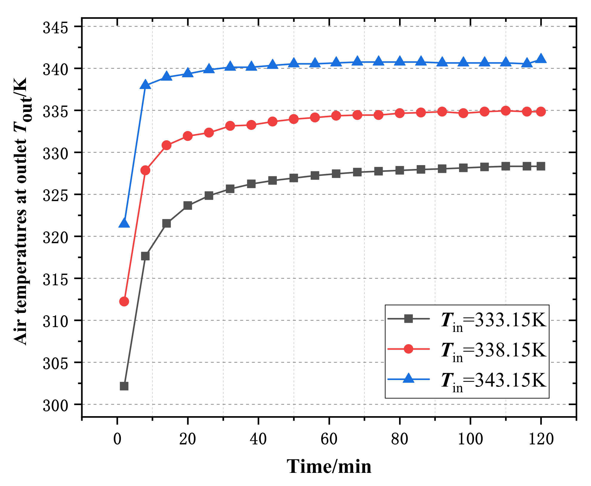
4.1.1. Influence of Wet Air Temperatures at Inlet on Outlet of Dehumidifier

When the volume flow V of the hot and wet air at the inlet of the dehumidifier is 5.0 m3/h and the temperature Tin is 333.15, 338.15 and 343.15 K, respectively, the variation relationships of the air temperature Tout at the outlet of the dehumidifier with the time are shown in Figure 7.
At the initial stage, when the hot and humid air enters the dehumidifier, Tout increases rapidly with the increase of time, and then Tout tends to be stable; that is, the heat exchange between the hot and humid air and the PCM tends to be stable throughout the heat pipe. When Tin = 333.15, 338.15 and 343.15 K, the temperatures when Tout reaches stability are 327.25, 334.85 and 340.15 K, respectively, and the times ts required are 50, 16 and 10 min, respectively. At this time, the temperature difference Δ T between Tin and Tout decreases to 279.05, 276.45 and 276.15 K, respectively. The reason is that the higher the Tin, the greater the temperature difference between the inlet hot and wet air and PCM, and the stronger the driving force of the heat transfer; At the same time, the higher the Tin, the greater the moisture content and total enthalpy of the wet air, and the moisture content and enthalpy change to a high power with the temperature. For PCM of the same quality, the time ts required to achieve a stable heat exchange is shorter, the Tout is higher, and then, Δ T decreases.

4.1.2. Effect of Wet Air Temperature at Dehumidifier Inlet on Temperature Field of Phase Change Heat Storage

In the experiments, when the hot and wet air enters the dehumidifier, its temperature is Tin = 333.15, 338.15 and 343.15 K, respectively, and the melting states of paraffin on the upper surface of the phase change heat storage photographed at different times are shown in Figure 8. In the early period of the heat exchange, the paraffin exists as a solid; the paraffin around the heat pipes absorbs heat and melts, and the main way for heat exchange between the heat pipes and paraffin is heat conduction. With the increase of the heat transfer time, the liquid paraffin gradually increases. Due to the density of the liquid being lower than that of the solid, the liquid begins to flow upward. At this period, the main way for heat transfer in the melting zone is natural convection. The higher the temperature of the hot and wet air entering the dehumidifier, the faster the paraffin melts.

4.2. Influences of Wet Air Flow Rate at Dehumidifier Inlet on Experimental Results

In this section, still taking CASE 4 as the object, the influences of hot and wet air flow rate at the inlet of dehumidifier on outlet air temperature and temperature field of phase change heat storage will be researched.

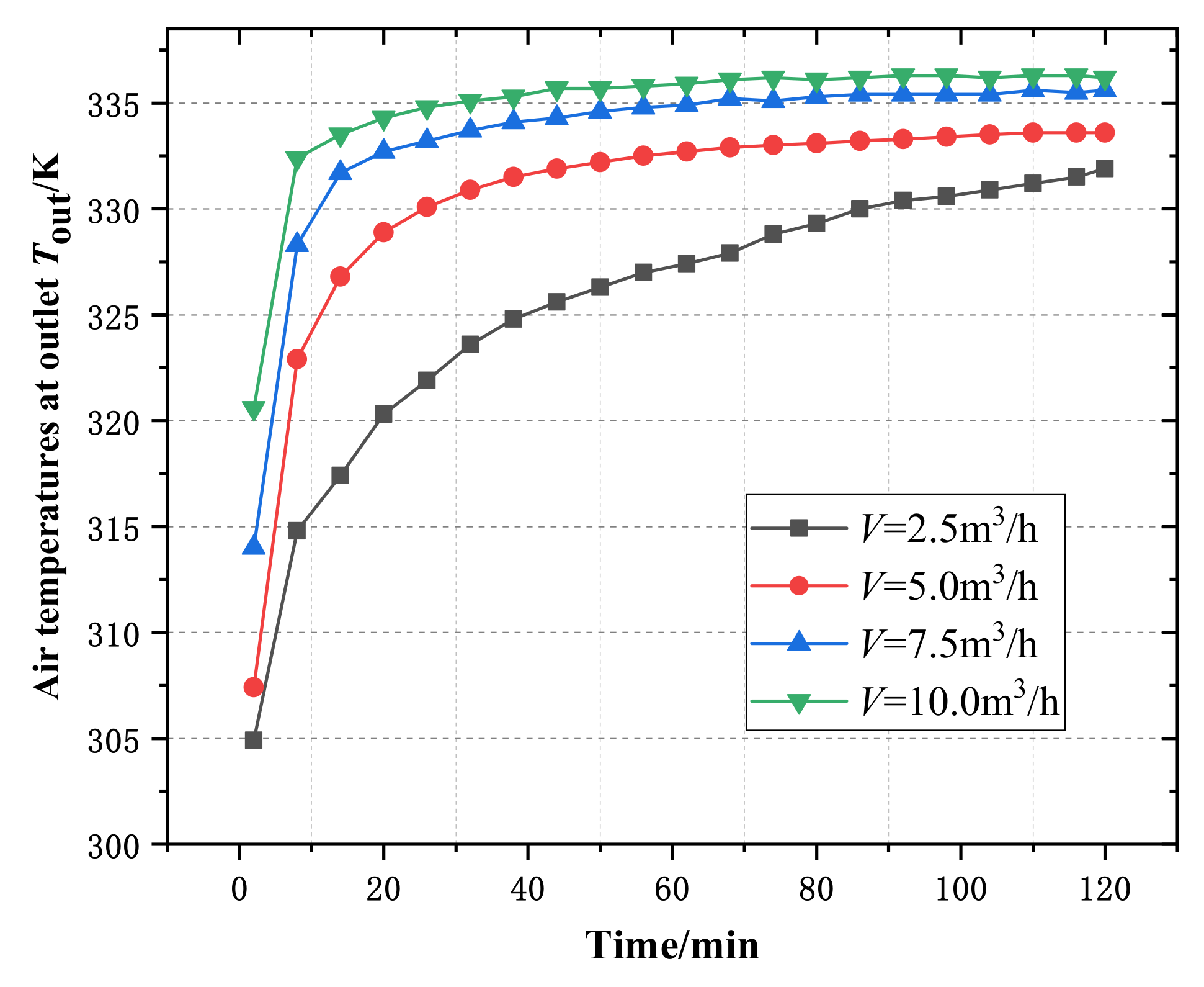
4.2.1. Influence of Inlet Wet Air Flow Rate of Dehumidifier on Outlet Air Temperature

Figure 9 shows the variation curve of the air temperature Tout at the outlet of the dehumidifier under experimental conditions when the inlet hot and wet air temperature of the dehumidifier is Tin = 338.15 K and the flow rates are 2.5, 5.0, 7.5 and 10.0 m3/h, respectively. In the experiment, the hot and wet air continuously transfers heat to the paraffin through the heat pipes, resulting in the melting of the paraffin after the temperature rises. The temperature difference between the hot end and the cold end of the same heat pipe decreases with the increase in time; that is, its heat transfer driving force decreases, resulting in the rise of the temperature Tout of the air out of the dehumidifier until Tout tends to be stable. When the total amount of paraffin remains unchanged, the greater the V, the greater the flow velocity of the hot and wet air, the faster the heat transfer and the shorter the time required for Tout to reach stability. The greater the V, the higher the total enthalpy of the hot and wet air, and the greater the stable value of Tout.

4.2.2. Effect of Inlet Wet Air Flow of Dehumidifier on Temperature Field of Phase Change Heat Storage

Under the experimental conditions, when the air volume flow is =2.5, 5.0, 7.5 and 10.0 m3/h, respectively, the melting state of paraffin on the upper surface of the phase change heat storage at different times is shown in Figure 10. It can be seen from the figure that, when other conditions are the same, the longer the heat exchange time, the greater the melting amount of paraffin. The greater the V, the faster the paraffin melts.
When the experiment lasted for 60 min and the flow rate of the hot and wet air at the inlet of the dehumidifier was 10.0 m3/h, the paraffin in each stage in the phase change heat storage was basically melted. At 2.5, 5.0 and 7.5 m3/h, respectively, the melting amount of paraffin in each stage of the phase change heat storage was about 60%, 70% and 80%. That is, the greater the wet air flow at the inlet of the dehumidifier, the greater the flow velocity, the faster the heat transfer and the faster the paraffin melted.

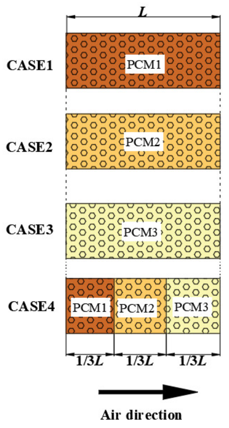
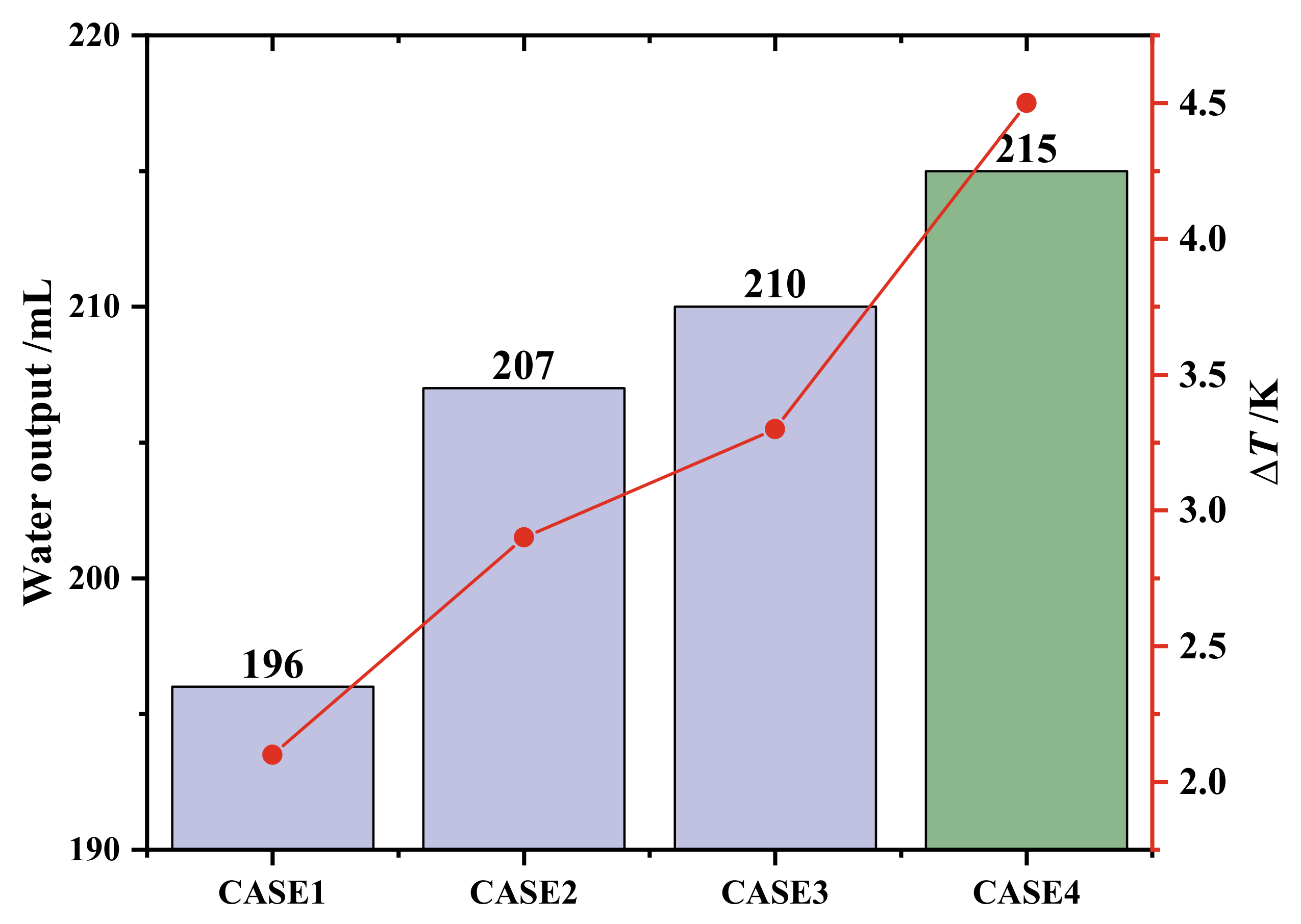
4.3. Comparison of Cascaded Number Layout of PCMs

Under the experimental conditions, when the air temperature Tin = 338.15 K and the air flow rate V = 5.0 m3/h at the inlet of the dehumidifier, the water output obtained after the experiment for 1h and the air temperature difference ΔT between Tin and Tout at the dehumidifier are shown in Figure 11.
It can be seen from Figure 11 that CASE4 has the highest water output and the largest air temperature difference at the inlet and outlet of the dehumidifier. It can be seen from Table 2 that the phase change latent heat and phase change temperature of PCM1, PCM 2 and PCM 3 decrease in turn. In CASE4, PCM1, PCM 2 and PCM 3 have the same volumes and are arranged in sequence. Their phase change temperatures decrease step by step, and the decreasing direction of the phase change temperature is consistent with that of the hot air temperature. Therefore, the temperature differences between each PCM and hot air are relatively small. When Tin = 338.15 K, the temperature ranges of the possible phase transitions of CASE4 and CASE1 are 321.15~338.15 K and 325.15~338.15 K, respectively; that is, the former has a wider temperature range of possible phase transition, more phase transition heat absorption and water output and greater temperature differences between the air inlet and outlet of the dehumidifier. Comparing CASE4 and CASE3, although their possible phase change temperature ranges are both 321.15~338.15 K, in Case4, because the phase change latent heat of PCM1 and PCM2 is greater than that of PCM3, the average phase change latent heat in CASE4 is greater than that of CASE3, the phase change heat absorption and water output are greater and the temperature difference between the air inlet and outlet of the dehumidifier is greater.
According to Formulas (5) and (6), the GOR and WPC of the experimental device under the above four different arrangement modes can be calculated. If a passive humidification and dehumidification seawater desalination device is installed above the phase change heat storage, the heat in the phase change heat storage is supplied to the passive humidification and dehumidification device by heat pipe for the secondary water output; the secondary water output M1 can be obtained from Formula (7). Figure 12 shows the GOR1 without a secondary water output and the GOR2 with a secondary water output according to Formula (5). Figure 13 shows the WPC1 without a secondary water output and the WPC2 with a secondary water output calculated by Formula (6).
CASE4 has the highest gain output ratio and the lowest water production cost. Compared with CASE1~CASE3, the gain output ratio increased by 9.69%, 3.86% and 2.40%, respectively, and the water production cost of CASE4 decreased by 8.82%, 3.69% and 2.31%, respectively. After the secondary water output by using the heat in phase change heat storage, the water production costs of various arrangements are reduced by 20%, and the gain output ratio is increased by 25%.

5. Conclusions

Based on the exergy analysis of cascaded phase change heat storage, the experimental system of a cascaded phase change heat storage dehumidifier was established, and some experimental studies were carried out. The conclusions are as follows.
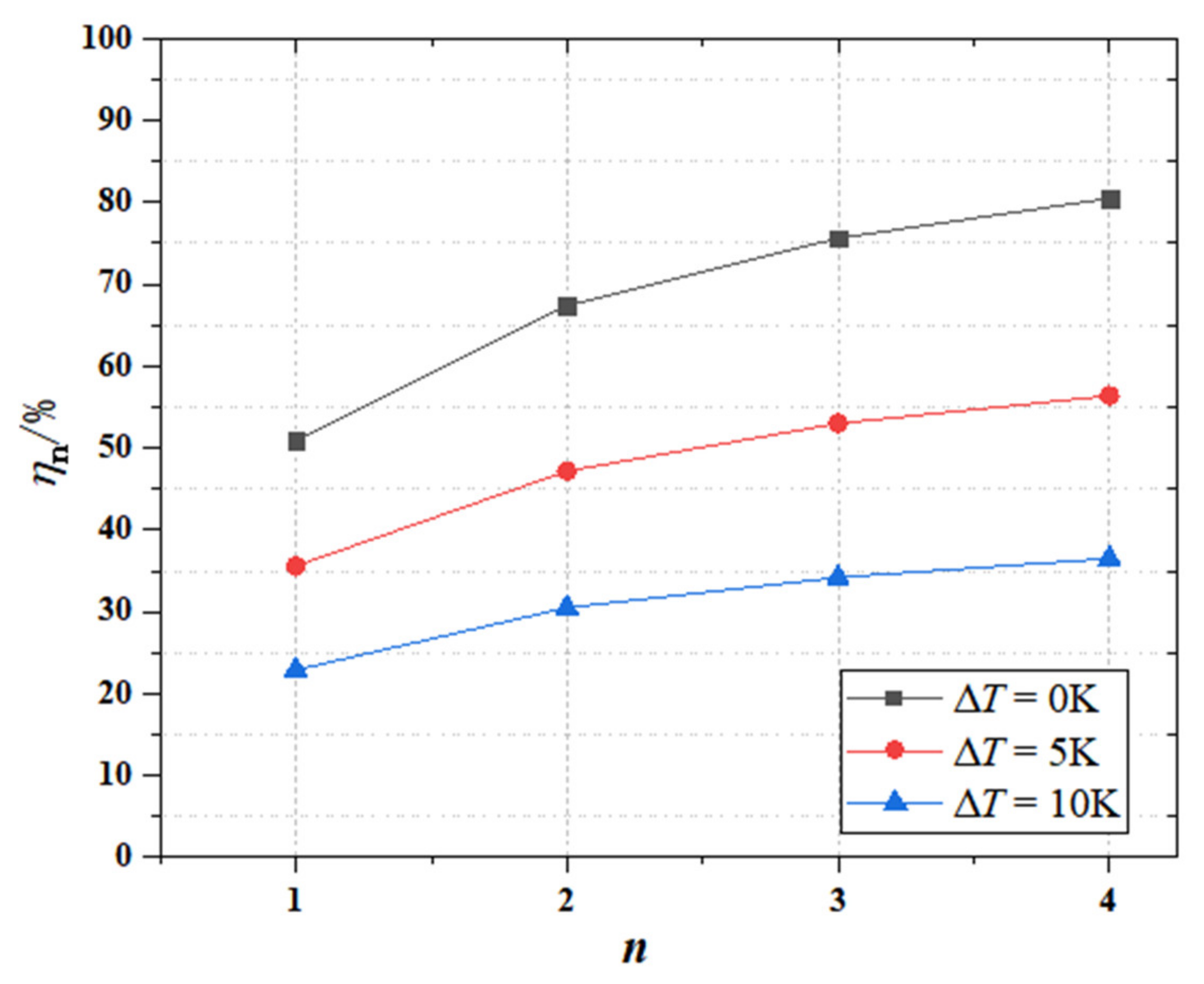
  • The more stages of phase change materials exit in the cascaded phase change heat storage, the greater the exergy efficiency will be, but the relationship between them is not linear. The increase rate of the exergy efficiency decreases with the increase of the stage numbers. Considering the above factors, the complexity of a multi-stage phase change heat storage device and the difficulty of selecting phase change materials, it is recommended to select the number of phase change material stages as three. When the ∆T is 5 K, and the n is equal to 3, the η n can reach a maximum of 53.0%.
  • With the increase of the temperature and volume flow of the wet air at the inlet of the dehumidifier, the time required for the air temperature at the outlet of the dehumidifier to reach stability is shortened, and the heat transfer capacity of the phase change heat storage dehumidifier is enhanced.
  • The cascaded layout of PCMs can improve the water production performance of a dehumidifier. When the hot and wet air temperature and the volume flow rate at the inlet of the dehumidifier are 338.15 K and 5.0 m3/h, compared with dehumidifiers with three kinds of PCM single-stage layouts, the GOR of the dehumidifier with a PCM three-stage layout is increased by 9.69%, 3.86% and 2.40%, and the WPC is reduced by 8.82%, 3.69% and 2.31%, respectively. If the heat in the phase change heat storage device is used for the secondary water output, the water output and GOR will be increased by 25%, and the WPC will be reduced by 20%.

Author Contributions

Conceptualization, L.Z.; methodology, L.Z.; software, Z.F. and Y.J.; validation, L.Z. and Y.J.; formal analysis, L.Z., K.W. and Z.F.; investigation, Z.F., L.Z. and Y.J.; data curation, Y.J.; writing—original draft preparation, Z.F., L.Z. and Y.J.; writing—review and editing, L.Z. and K.W.; visualization, Y.J. and supervision, L.Z. All authors have read and agreed to the published version of the manuscript.

Funding

This research received no external funding.

Institutional Review Board Statement

Not applicable.

Informed Consent Statement

Not applicable.

Data Availability Statement

Not applicable.

Conflicts of Interest

The authors declare no conflict of interest.

References

  1. Mahdi, J.M.; Lohrasbi, S.; Nsofor, E.C. Hybrid heat transfer enhancement for latent-heat thermal energy storage systems: A review. Int. J. Heat Mass Transf. 2019, 137, 630–649. [Google Scholar] [CrossRef]
  2. Al-Maghalseh, M.; Mahkamov, K. Methods of heat transfer intensification in PCM thermal storage systems: Review paper. Renew. Sustain. Energy Rev. 2018, 92, 62–94. [Google Scholar] [CrossRef]
  3. Christopher, S.; Parham, K.; Mosaffa, A.H.; Farid, M.M.; Ma, Z.; Thakur, A.K.; Xu, H.; Saidur, R. A critical review on phase change material energy storage systems with cascaded configurations. J. Clean. Prod. 2021, 283, 124653. [Google Scholar] [CrossRef]
  4. Huang, X.; Zhu, C.; Lin, Y.; Fang, G. Thermal properties and applications of microencapsulated PCM for thermal energy storage: A review. Appl. Therm. Eng. 2019, 147, 841–855. [Google Scholar] [CrossRef]
  5. Zayed, M.E.; Zhao, J.; Elsheikh, A.H.; Hammad, F.A.; Ma, L.; Du, Y.; Kabeel, A.E.; Shalaby, S.M. Applications of cascaded phase change materials in solar water collector storage tanks: A review. Sol. Energy Mater. Sol. Cells 2019, 199, 24–49. [Google Scholar] [CrossRef]
  6. Farid, M.M.; Kanzawa, A. Thermal performance of a heat storage module using pcm’s with different melting temperatures: Mathematical modeling. J. Sol. Energy Eng. Trans. ASME 1989, 111, 152–157. [Google Scholar] [CrossRef]
  7. Xu, Y.; He, Y.-L.; Li, Y.-Q.; Song, H.-J. Exergy analysis and optimization of charging–discharging processes of latent heat thermal energy storage system with three phase change materials. Sol. Energy 2016, 123, 206–216. [Google Scholar] [CrossRef]
  8. Li, B.; Zhai, X.; Cheng, X. Thermal performance analysis and optimization of multiple stage latent heat storage unit based on entransy theory. Int. J. Heat Mass Transf. 2019, 135, 149–157. [Google Scholar] [CrossRef]
  9. Khor, J.O.; Sze, J.Y.; Li, Y.; Romagnoli, A. Overcharging of a cascaded packed bed thermal energy storage: Effects and solutions. Renew. Sustain. Energy Rev. 2020, 117, 109421. [Google Scholar] [CrossRef]
  10. Shamsi, H.; Boroushaki, M.; Geraei, H. Performance evaluation and optimization of encapsulated cascade PCM thermal storage. J. Energy Storage 2017, 11, 64–75. [Google Scholar] [CrossRef]
  11. Zhao, Y.; You, Y.; Liu, H.B.; Zhao, C.Y.; Xu, Z.G. Experimental study on the thermodynamic performance of cascaded latent heat storage in the heat charging process. Energy 2018, 157, 690–706. [Google Scholar] [CrossRef]
  12. Huang, H.; Xiao, Y.; Lin, J.; Zhou, T.; Liu, Y.; Zhao, Q. Improvement of the efficiency of solar thermal energy storage systems by cascading a PCM unit with a water tank. J. Clean. Prod. 2020, 245, 118864. [Google Scholar] [CrossRef]
  13. Hassanpour, A.; Borji, M.; Ziapour, B.M.; Kazemi, A. Performance analysis of a cascade PCM heat exchanger and two-phase closed thermosiphon: A case study of geothermal district heating system. Sustain. Energy Technol. Assess. 2020, 40, 100755. [Google Scholar] [CrossRef]
  14. Cheng, X.; Zhai, X. Thermal performance analysis and optimization of a cascaded packed bed cool thermal energy storage unit using multiple phase change materials. Appl. Energy 2018, 215, 566–576. [Google Scholar] [CrossRef]
  15. Majumdar, R.; Saha, S.K. Computational study of performance of cascaded multi-layered packed-bed thermal energy storage for high temperature applications. J. Energy Storage 2020, 32, 101930. [Google Scholar] [CrossRef]
  16. Wang, H.; Liu, Z.; Yao, Y.; Wu, H. Visualized experiment on solid-liquid phase change heat transfer enhancement with multiple PCMs. J. Chem. Ind. Eng. 2019, 70, 1263–1271. [Google Scholar]
  17. Zhu, Y.; Wang, D.; Li, P.; Yuan, Y.; Tan, H. Optimization of exergy efficiency of a cascaded packed bed containing variable diameter particles. Appl. Therm. Eng. 2021, 188, 116680. [Google Scholar] [CrossRef]
  18. Riahi, S.; Liu, M.; Jacob, R.; Belusko, M.; Bruno, F. Assessment of exergy delivery of thermal energy storage systems for CSP plants: Cascade PCMs, graphite-PCMs and two-tank sensible heat storage systems. Sustain. Energy Technol. Assess. 2020, 42, 100823. [Google Scholar] [CrossRef]
  19. Mahdi, J.M.; Mohammed, H.I.; Hashim, E.T.; Talebizadehsardari, P.; Nsofor, E.C. Solidification enhancement with multiple PCMs, cascaded metal foam and nanoparticles in the shell-and-tube energy storage system. Appl. Energy 2020, 257, 113993. [Google Scholar] [CrossRef]
  20. Mawire, A.; Ekwomadu, C.S.; Lefenya, T.M.; Shobo, A. Performance comparison of two metallic eutectic solder based medium-temperature domestic thermal energy storage systems. Energy 2020, 194, 116828. [Google Scholar] [CrossRef]
  21. Suresh, C.; Saini, R. Experimental study on combined sensible-latent heat storage system for different volume fractions of PCM. Sol. Energy 2020, 212, 282–296. [Google Scholar]
  22. Cheng, X.; Zhai, X.; Zheng, C. Performance Analysis and Optimization of a Cascade PCM Cold Storage Heat Exchanger. J. Shanghai Jiao Tong Univ. 2016, 50, 1500–1505, 1513. [Google Scholar]
  23. Zheng, Z.; Xu, Y.; He, Y. Study on the Performance of a Shell-and-Tube Latent-Heat Storage Unit Enhanced by Porous Medium with Graded Porosity. J. Eng. Thermophys. 2019, 40, 605–611. [Google Scholar]
  24. Ahmed, N.; Elfeky, K.; Lu, L.; Wang, Q. Thermal performance analysis of thermocline combined sensible-latent heat storage system using cascaded-layered PCM designs for medium temperature applications. Renew. Energy 2020, 152, 684–697. [Google Scholar] [CrossRef]
  25. Elfeky, K.E.; Li, X.; Ahmed, N.; Lu, L.; Wang, Q. Optimization of thermal performance in thermocline tank thermal energy storage system with the multilayered PCM(s) for CSP tower plants. Appl. Energy 2019, 243, 175–190. [Google Scholar] [CrossRef]
  26. Tehrani, S.S.M.; Shoraka, Y.; Nithyanandam, K.; Taylor, R.A. Cyclic performance of cascaded and multi-layered solid-PCM shell-and-tube thermal energy storage systems: A case study of the 19.9 MWe Gemasolar CSP plant. Appl. Energy 2018, 228, 240–253. [Google Scholar] [CrossRef]
  27. Mao, Q.; Zhang, Y. Thermal energy storage performance of a three-PCM cascade tank in a high-temperature packed bed system. Renew. Energy 2020, 152, 110–119. [Google Scholar] [CrossRef]
  28. Hu, F.; Lu, D.; Zhao, P.; Chen, Z. Thermodynamic analysis on optimum phase change temperature for multiple phase change materials. J. Chem. Ind. Eng. 2013, 64, 2322–2327. [Google Scholar]
  29. Hamed, M.H.; Omara, Z.M.; Sharshir, S.W.; Kabeel, A.E. Mathematical and experimental investigation of a solar humidification-dehumidification desalination unit. Desalination 2015, 358, 9–17. [Google Scholar] [CrossRef]
  30. Khayet, M. Solar desalination by membrane distillation: Dispersion in energy consumption analysis and water production costs (a review). Desalination 2013, 308, 89–101. [Google Scholar] [CrossRef]
  31. Zhang, H.F. Principle of Solar Thermal Utilization and Computer Simulation, 2nd ed.; Northwestern Polytechnical University Press: Xi’an, China, 2012; pp. 222–223. [Google Scholar]
Figure 1. Fluid temperature variation in the cascaded phase change heat storage process.
Applsci 12 01303 g001
Figure 2. Exergy efficiency of the thermal fluid, η n /%.
Applsci 12 01303 g002
Figure 3. Structural diagram of a cascaded phase change heat storage dehumidifier.
Applsci 12 01303 g003
Figure 4. Working principle of the cascaded phase change heat storage dehumidifier.
Applsci 12 01303 g004
Figure 5. Schematic diagram of different arrangements of PCMs.
Applsci 12 01303 g005
Figure 6. Experimental system of the cascaded phase change heat storage dehumidifier.
Applsci 12 01303 g006
Figure 7. Variations of air temperatures at the outlet of dehumidifier with time at different inlet wet air temperatures.
Applsci 12 01303 g007
Figure 8. Melting of paraffin on the upper surface of phase change heat storage for CASE4 at different Tin.
Applsci 12 01303 g008
Figure 9. Variation of air temperatures at the outlet of dehumidifier with time at different inlet wet air flow rates.
Applsci 12 01303 g009
Figure 10. Melting of paraffin on the upper surface of phase change heat storage for CASE4 at different V.
Applsci 12 01303 g010
Figure 11. Water output and ΔT under different arrangements of PCMs.
Applsci 12 01303 g011
Figure 12. GOR1 and GOR2 under different arrangements of PCMs.
Applsci 12 01303 g012
Figure 13. WPC1 and WPC2 under different arrangements of PCMs.
Applsci 12 01303 g013
Table 1. Optimum phase change temperature in each stage of the cascaded phase change heat storage device.
Δ T / K Stage Number i T opt , n , i / K
n = 1n = 2n = 3n = 4
01312.79317.83320.38321.92
2307.80312.79315.80
3305.38309.81
4303.90
51310.40314.59316.71317.99
2306.26310.40312.91
3304.21307.91
4302.99
101307.99311.34313.03314.05
2304.67307.99309.99
3303.03305.99
4302.05
Table 2. Phase change temperature and melting latent heat of the phase change materials.
PCMPhasePhase Change Temperature/KMelting Latent Heat/(kJ/kg)
PCM1Solid325.15210.3
PCM2Solid323.15179.0
PCM3Solid321.15160.0
Publisher’s Note: MDPI stays neutral with regard to jurisdictional claims in published maps and institutional affiliations.

