Abstract
In this paper, laser surface treatment of Al alloy was studied by comparison of sandblasting and laser ablation. The effects of laser spot distribution on surface roughness, contact angle, chemical composition and shear strength of Al alloy were analyzed. The experimental results showed that the bonding performance of Al alloy are promoted by controlling the laser spot spacing. When laser spot spacing was smaller than the size of the laser spot, micro–nano composite structures were induced by multiple laser pulses, which would improve shear strength by increasing the contact area between Al alloy and adhesive. Using laser surface treatment, the adhesion properties on Al alloy can be promoted.
1. Introduction
Aluminum (Al) alloy is popularly applied in the fields of aviation, aerospace and vehicles, owing to its high strength, light weight and good corrosion resistance [1]. Since Al alloy is used as the material for adhesively bonded joints, its surface pretreatment is one of the most important processes before adhesive bonding [2]. Traditionally, the surface of Al alloy is treated by sandblasting to increasing the shear strength. However, dust contaminants may adhere to the surface of the substrate after sandblasting, which affects the shear strength and would lead to hazards of the products.
To enhance the adhesion on Al alloy, the surface pretreatment methods including chemical etching, electroplating and sandblasting have been developed in recent years [3,4,5,6,7,8,9,10,11,12,13,14,15,16]. As demonstrated by Zhou J. et al., the shear strength of Al alloy after chemical etching was as high as 20.4 MPa [13]. Wang X.’s group showed the shear strength pretreated with different chemical reagents was 20% higher [14]. Yang Fubiao used the anodizing method to treat Al alloy pieces and enhanced the bonding behaviors [15]. Sancaktar combined chemical modification and post-sandblasting, which resulted in better shear strength. However, the above methods still faced serious challenges, namely, high labor cost, complex processes and chemical pollution [16].
Laser surface treatment, a non-contact and environment-friendly technique, is promising for use in industrial products over conventional processing methods [17,18,19]. Richard showed that the shear strength of laser-treated Al alloy surface was similar to that by chemical-etching and electroplating [20]. Molitor used excimer lasers to perform the surface treatments on alloy and the shear strength was controlled by laser fluence [21]. Huang found that microstructures produced in the laser irradiation could result in an increase of surface area and therefore in better bonding performance [22]. Recently, it was found that the type of laser-produced microtexture on the surface also had a significant impact on bonding performance [23,24,25].
It has been proven by previous investigation [26] that nano-structured surface could enhance the bonding behavior of metals. Our current work was focused on the influence of micro/nano structures on the adhesive bonding strength of Al alloy. The surface roughness, chemical composition, contact angle and shear strength were analyzed before and after surface treatment. By controlling the laser spot spacing, the laser-induced micro–nano composite structures were formed on the surface of Al alloy and its shear strength became larger than the sandblasting method. These results offer an alternative approach in the field of surface pre-treatment of aluminum and its alloys.
2. Materials and Methods
2.1. Sample Preparation
Al alloy (2A12) is a relatively high strength duralumin material, which is a composition of Cu (3.8–4.9%), Mg (1.2–1.8%), as well as smaller percentages of Ag, Ni, Fe, Si, Mn, Zn and Ti. The material used in this study was pre-cut into small plates with dimensions of 70 mm × 20 mm × 2 mm. In the middle of the plates, a hole with a diameter of 8 mm was prepared to ensure subsequent shear strength tests. After pre-treatment, the sample surface was rinsed with alcohol to rid of the impurity. Seen in Figure 1, two samples under the same treatment condition were pasted with 8-mm overlap, which was adhesive bonding area and pre-treated with laser ablation, and then cured using jig under high pressure for several hours.
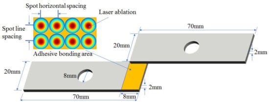
Figure 1.
Schematic diagram of adhesive bonding of Al alloy samples.
2.2. Experimental Method
The experiment setup for surface treatment was presented in Figure 2. Nanosecond laser pulses were emitted by a commercial fiber laser system (IPG Company, New York, NY, USA), and then delivered to a scanning Galvanometer (Scanlab Company, Puchheim, Germany). The maximum laser power was 30 W, the average laser wavelength was 1064 nm and the pulse width was 100 ns. Passing through an F-θ field lens with 160-mm focal length, the laser beam was focused to be a spot with diameter 30 μm at 1/e2 of the maximum laser intensity. To ensure the laser focusing on the top surface of samples, the distance between the laser spot and the samples was adjusted by Z-axis lifting stage. The line spacing of laser spot (ranged from 10 μm to 100 μm) and the scanning speed (ranged from 100 mm/s to 10,000 mm/s) were accurately controlled with the scanning Galvanometer. The inset of Figure 1 showed pictures of an untreated sample (No.1), a sandblasted sample (No.2) and four laser-treated samples (from No.3 to No.6).
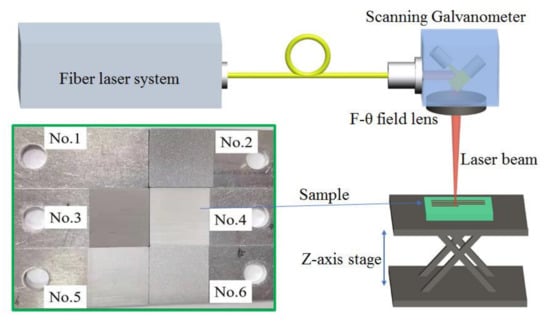
Figure 2.
Experiment setup for laser surface treatment. The inset showed pictures of Al alloy samples before treatment (No.1), after sandblasting (No.2) and laser surface treatment (No.3–No.6).
To explore the influence of multiple laser pulses on the bonding performance Al alloy, the laser-treating experiment was conducted under the same condition except spot spacing. The laser power was 30 W and laser frequency was 40 KHz, considering energy utilization and processing efficiency. By adjusting the scanning speed of laser pulses, the spot horizontal spacing was increased from 10 μm to 70 μm, with a step of 20 μm. To be simplified, the spot line spacing was set as same as the spot horizontal spacing. The experimental parameters for No.3–No.6 samples were briefly summarized in Table 1. The laser track was consisted of a matrix of spots with different spacing.

Table 1.
Experimental parameters for laser surface treatment.
In order to test the adhesive bonding strength of Al alloy, the sample surface was treated with sandblasting or laser treating and two samples were handled for each experimental parameter. The detection instruments used in the experiment include the following. Firstly, the samples were examined with an optical microscope (Olympus Company, BX51, Tokyo, Japan). By white light interferometer (WLI, ZYGO Company, Nexview9000, California, USA), surface roughness including Sa, Sq and Sz were measured, where Sa was the average absolute value of height difference of all points in the measured region, Sq was the root-mean-square value of height, and Sz was the sum value of the maximum peak height and the maximum valley depth. To characterize wettability, the contact angle of substrate surface was explored with JC2000C4 Contact Angle tester. Scanning electron microscope (SEM, Leo Company, Leo-1450, Berlin, Germany) was used to measure the surface morphology and energy spectrum of the samples. Then, 944 adhesive was coated on the treating area (shown in Figure 1) and the two samples of the same treatment were pasted with the following processing of RT → 80 °C/2 h → 100 °C/2 h → 150 °C/6 h → natural cooling. Finally, the shear strength test was conducted on the technical standard of G4-853-81.
3. Results and Discussion
3.1. Analysis of Surface Roughness Detection Results
Figure 3 showed the morphology and surface roughness of No.1, No.2 and No.3–No.6 samples, which were untreated, treated by sandblasting and laser ablation, respectively. The test area for roughness was 1.5 mm × 1.5 mm. It was seen from the No.1 sample that the surface of the original substrate was relatively smooth with Sa = 0.37 μm. Parallel stripes formed on the No.1 sample surface, because the surface line groove morphology was rolled during the manufacturing process. The surface of No.2 sample had concave–convex structures in different directions, instead of rolling streaks in the fixed orientation. Under laser irradiation, the Al alloy sample was heated intensively and melted at the laser spot, which produced a localized melt pool. The center of the melt pool was rendered as pit, where some of melted material were vaporized and removed by high-intense laser ablation. Because of the laser impact force, the remaining melted part was squeezed out from the pits and extruded each other, which finally formed a spike at the edge of melt pool. As the laser spot travelled under a designed track, a large number of spikes and pits occurred on the surface of No.3–No.6 samples, which were consistent with the reported experiment results [27,28]. Observed from No.5 and No.6 samples, the diameter of a single pit was around 40 μm, which implied that the laser ablation area was a little bigger than the laser spot. When the spot spacing was smaller than or equivalent with the diameter of the laser spot, pits on the No.3 and No.4 sample surface were much smaller than those of No.5 and No.6 samples. Due to a small overlap of successive laser tracks, multiple laser pulses acted upon the same melt pool, which made more spikes and reduced the area of each pit. Thus, the constructed structure on the surface of No.3 and No.4 samples were different from those of No.5 and No.6 samples.
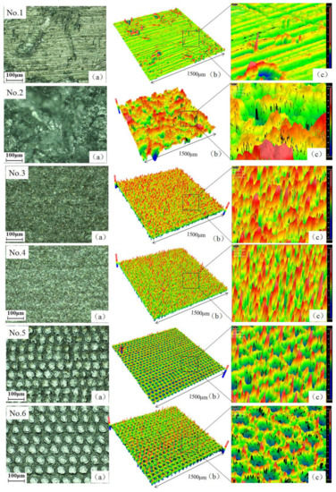
Figure 3.
Topography and surface roughness test diagram of No.1–No.6 sample. (a) Topography was measured by optical microscope; (b,c) Surface roughness was measured by white light interferometer.
Figure 4 showed the Sa, Sq and Sz test maps of surface roughness of No.1–No.6 samples. The surface roughness Sa, Sq and Sz values of the original substrate were the lowest, while that of the No.2 sample treated by sandblasting was the highest. The surface roughness of samples No.3–No.6 decreased gradually by increasing the horizontal and line spacing of laser spot. The laser-treatment results showed that the morphology and surface roughness of the sample could be controlled by adjusting the laser spot distribution without changing the laser power. Compared with the No.1 sample, the surface roughness of the sample after laser treating was increased. However, compared with No.2 sandblasted samples, the surface roughness of laser treated samples was relatively lower.
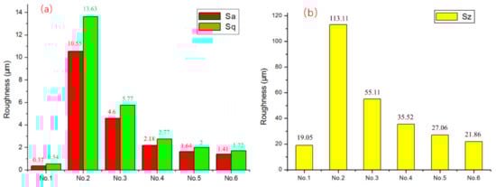
Figure 4.
Surface roughness of No.1–No.6 Sample. (a) Values of Sa and Sq; (b) Value of Sz.
3.2. Analysis of Microscopic Morphology and Contact Angle Detection Results
Shown in Figure 5, the microstructure and contact angle of No.1 and No.2 samples were measured by SEM and contact angle measuring instrument. Alcohol was used to clean oil stains on the surface of the No.1 sample. After cleaning, there was still a layer of loose and uneven oxide film on the surface [29], which reduced the surface energy of Al alloy. The wettability of the No.1 sample was affected. There was a small physical adsorption force between droplet and Al alloy surface results in small mechanical meshing force [30] and a contact angle of 89°. There were obvious rolling cracks on the surface of Al alloy; these cracks were easy to be the source of crack propagation during service. The metal surface of the No.2 sample was coarsened and purified by random collision and repeated scouring of sand particles. Impurities, such as oxide on the substrate surface, were removed. Large bumps and pits appeared on the surface of the No.2 sample, which were in no obvious directionality, with multi-scale and random characteristics. After sandblasting, its contact area increased and the surface wettability improved with a contact angle of 51.4°. Micro-pits, scratches and furrows generated on the sample surface played the role similar to mechanical occlusion, anchoring and nailing [30]. Thus, the wettability of Al alloy was improved after sandblasting.
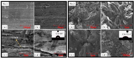
Figure 5.
SEM images showing details of surface structure of No.1 sample (untreated) and No.2 sample (sandblasted). Form (a–d), the image magnification were monotone increasing.
Because the hemispherical melting region impacted by laser beam overlapped with each other, the interaction of stacking and extrusion was enhanced and the surface of the No.3 and No.4 samples forms a uniform rough structure, seen in Figure 6. This increased the contact area between the droplet and the samples. The surface contact angle of No.3 and No.4 sample was 4.88° and 5.17°, respectively. Figure 6a showed a large number of “micron clusters”, which formed a uniform “coral” rough surface. According to the mechanical interlocking theory [31], the adhesive formed a stronger mechanical interlocking force on the surface, which increased the bonding area and then improved the bonding performance of the sample. Figure 6c,d shows the surface of “micron cluster” covered with a large number of nano-floc structures. The micro–nano composite structures further increases the contact area between the droplet and the material. When the droplet filled the pits on the surface of the coarse micro–nano structure of the flocculent, the droplet was completely sucked into the surface and formed infiltration. The surface of Al alloy became hydrophilic. It should be noticed that WLI and SEM methods both provided surface morphology, however, their test diagram did not appear the same thing [32,33]. Because of higher resolution in the Z direction for the WLI method, the spikes and pits in WLI images seemed taller with sharper appearance than in SEM images. Furthermore, as SEM overcame the limitations of the optical diffraction, the magnification of SEM images was up to 1000 times larger than WLI. As a result, micro–nano composite structures could be seen in SEM images.
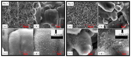
Figure 6.
SEM images of No.3 and No.4 samples treated by small spot spacing. Micro spikes and pits were covered with nano structures. Reference bars on these figures from (a–d) were 50 μm, 5 μm, 2 μm, and 1 μm, respectively.
Figure 7a showed that circular pits were regularly arranged on the surface of No.5 and No.6 samples when the distance between laser spots was equal to or greater than the diameter of the melting zone. From the accumulation phenomenon at the edge of pits, it implied that the main reason for the formation of pits was not material evaporation. It was formed by the impact of laser melting to melt the metal and pushed out of the molten pool. The edge of the pits showed irregular independent mastoid structures. Figure 7d showed a dense layer of granular nano protrusions on the surface of the pit, which did not produce floccule. The surface contact angle of No.5 and No.6 sample was 87.9° and 89.6°, which was similar to that of untreated subtract. Air might exist in the uniform pits and mastoid structures of the sample surface when the droplets contacted with Al alloy. The droplets were pushed out and could not get in. Therefore, the contact area between droplet and the samples was small, which performed as hydrophobicity.
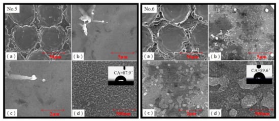
Figure 7.
SEM images of No.5 and No.6 samples treated by large laser spot spacing. Reference bars on these figures from (a–d) were 50 μm, 5 μm, 2 μm, and 500 nm, respectively.
The change in the contact angle of Al alloy after laser treatment was mainly affected by the surface morphology, roughness and structures of the substrate. The impact of the laser stress and thermal energy was to generate micro–nano structures, which made the surface rougher and caused the contact area to become larger. The contact mode between the droplet and Al alloy was changed. The surface of No.3 and No.4 samples was covered with a floc-like composite structure, which had greater adhesion. When the droplet affected the concave surface of the micro–nano structures of the floc, the droplet was completely sucked into the surface to form penetration, and the surface of No.3 and No.4 samples was therefore hydrophilic. The nano structures covered the micro structures to form a secondary rough structure. This double rough structure was conducive to the hydrophilic state of the water droplets on the surface of the material. No.5 and No.6 samples had uniform pits on the surface of the sample. When the droplets contacted the surface of No.5 and No.6 samples, air in the concave surface was squeezed to restrict itself from leaking out and form a stable gas chamber, which made droplets squeeze out. The actual contact area was smaller than the coverage area of the droplet on the surface, and thus behaved in a hydrophobic way at this time.
3.3. Analysis of Energy Spectrum Detection Results
Figure 8 presents a typical surface energy spectrum of Al alloy from the No.1 sample surface and the test range, which was 1 mm × 1 mm. Table 2 showed EDS energy spectrum test data of No.1–No.6 samples. Al, C and O were the main components in the original alloy. Si and other substances were added on the surface of the No.2 sample treated by sandblasting. The contents of C and O were increased greatly because the sand dust produced in the process of sandblasting adhered to the sample surface. An increase in residual quality resulted in a change in chemical composition. Al content on No.3 and No.4 samples decreased and O content increased, indicating that Al2O3 was oxidized and produced on the sample surface during laser ablating [34]. No.5 and No.6 samples were similar to No.1 sample in composition. Al, C and O contents did not change significantly and no new chemical composition was added after laser treatment.
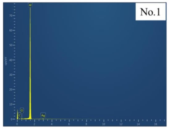
Figure 8.
Typical surface energy spectrum of Al alloy.
Table 2.
Results of energy spectrum of No.1–No.6 samples.
3.4. Analysis of Shear Strength Test Results
Seen in Figure 9, the shear strength of samples after treatment became larger, as the original sample was 7.1 MPa. By sandblasting, a certain amount of dirt remained in pits that mad adhesive difficult to enter. This led to interfacial voids and defects, which were easy to form a “weak interface layer” and reduce the shear strength after bonding. In addition, the particles adhered to the sample surface after sandblasting, which reduced bonding strength. After laser treatment, the shear strength of No.3 and No.4 samples was better than that by a sandblasting treatment of 17.2 MPa. The shear strength of Al alloy was controlled just by changing the laser spot distribution. By decreasing the spot spacing to smaller than 30 μm, which was the diameter of the laser spot, micro–nano structures were induced by multipulse interaction. Due to the hemispherical melting region of laser beam impact overlap, micro–nano composite structures were formed on the No.3 and No.4 sample surface, which increased the contact area between the adhesive and the metal. No.5 and No.6 samples had uniform pits and mastoid structures with air. The adhesive was squeezed out, which resulted in a smaller contact area and weaker bonding performance.
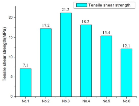
Figure 9.
Shear strength of No.1–No.6 sample.
4. Conclusions
It can be concluded that surface roughness, contact angle and shear strength of Al alloy was controllable by laser surface treatment. Compared with the sandblasting process, the shear strength of Al alloy was significantly improved by adjusting the laser spot distribution. As the spot spacing was smaller than the laser spot diameter, micro–nano composite structures were induced by multiple laser pulses. As a result, the shear strength of Al alloy and adhesive was enhanced by increasing their contact area. This could realize the replacement of the traditional method and was a good prospect for technological upgrading.
Author Contributions
Conceptualization, investigation, writing–original draft preparation, G.L.; methodology, Z.W.; formal analysis, C.L.; validation, K.L. and B.L.; writing–review and editing, M.L.; supervision, J.W.; project administration, X.W. All authors have read and agreed to the published version of the manuscript.
Funding
This research was funded by the National Key R&D Program of China (2017YFB1104604, 2016YFB1102503).
Institutional Review Board Statement
Not applicable.
Informed Consent Statement
Not applicable.
Data Availability Statement
Not applicable.
Conflicts of Interest
The authors declare no conflict of interest.
References
- Han, H.M.; Han, J.P.; Song, K.W.; Zhu, L.J. A method of laser purge aluminum alloy. J. Solid Rocket Technol. 2017, 40, 776–779. [Google Scholar]
- Gao, W.; Chen, X.P.; Han, J.P.; Liu, X.D. Progress in the fabrication process of composite joint skirt for srm. Fiber Reinf. Plast./Compos. 2016, 7, 92–95. [Google Scholar]
- Strauss, D.; Müller, G.; Schumacher, G.; Engelko, V.; Stamm, W.; Clemens, D.; Quaddakers, W.J. Oxide scale growth on MCrALY bond coating after pulsed electron beam treatment and deposition of EB-PVD TBC. Surf. Coat. Technol. 2001, 135, 196–201. [Google Scholar] [CrossRef]
- Weng, Y.X.; Liang, Z.J. Metal Bonding Technology; Chemical Industry Press: Beijing, China, 2006; pp. 110–125. [Google Scholar]
- Zettlemoyer, A.C. Treatise on adhesion and adhesives. J. Colloid Interface Sci. 1974, 48, 178–179. [Google Scholar] [CrossRef]
- Critchlow, G.W.; Brewis, D.M. Review of surface pretreatments for aluminium alloys. Int. J. Adhes. Adhes. 1995, 15, 161–172. [Google Scholar] [CrossRef]
- Critchlow, G.W.; Brewis, D.M. Influence of surface macroroughness on the durability of epoxide-aluminium joints. Int. J. Adhes. Adhes. 1995, 15, 173–176. [Google Scholar] [CrossRef]
- Prolongo, S.G.; Urena, A. Effect of surface pre-treatment on the adhesive strength of epoxy–Aluminium joints. Int. J. Adhes. Adhes. 2009, 29, 23–31. [Google Scholar] [CrossRef]
- Filbey, J.A.; Wightman, J.P. Factors affecting the durability of Ti-6Al-4V/ epoxy bonds. J. Adhes. 1989, 28, 1–22. [Google Scholar] [CrossRef]
- Locke, M.C.; Marceau, J.A.; Harriman, K.M. Chromic Acid-Fluoride Anodizing Surface Treatment for Titanium; Boeing Company: Seattle, WA, USA, 1984. [Google Scholar]
- Moji, Y.; Marceau, A.J. Method of Anodizing Titanium to Promote Adhesion; Boeing Company: Seattle, WA, USA, 1976. [Google Scholar]
- Mertens, T.; Gammel, F.J.; Kolb, M. Investigation of surface pre-treatments for the structural bonding of titanium. Int. J. Adhes. Adhes. 2012, 34, 46–54. [Google Scholar] [CrossRef]
- Zhou, J.F.; Li, A.; Rao, B.L. Effect of metal surface treatment and bonding technology on shear strength. Chem. Adhes. 2007, 29, 30–32. [Google Scholar]
- Wang, X.M. Application of Silane Coupling Agent in Metal Pretreatment and Organic Coating; Shandong University: Weihai, China, 2005; pp. 20–25. [Google Scholar]
- Yang, F.B.; Xiao, J.Y.; Zeng, J.C. The phosphoric acid anodizing of aluminum alloys for adhesive bonding. J. Mater. Eng. 2006, 2, 7–11. [Google Scholar]
- Sancaktar, E.; Gomatam, R.A. Study on the effect of surface roughness on the strength of single lap joints. J. Adhes. Sci. Technol. 2001, 15, 97–117. [Google Scholar] [CrossRef]
- Molitor, P.; Barron, V.; Young, T. Surface treatment of titanium for adhesive bonding to polymer composites: A review. Int. J. Adhes. Adhes. 2001, 21, 129–136. [Google Scholar] [CrossRef]
- Rechner, R.; Jansen, I.; Beyer, E. Influence on the strength and aging resistance of aluminium joints by laser pre-treatment and surface modification. Int. J. Adhes. Adhes. 2010, 30, 595–601. [Google Scholar] [CrossRef]
- Sancaktar, E.; Lee, J.S. Reliability, Stress Analysis and Failure Prevention Aspects of Composite and Active Materials; ASME: New York, NY, USA, 1994. [Google Scholar]
- Broad, R.; French, J.; Sauer, J. CLP new, effective, ecological surface pretreatment for highly durable adhesively bonded metal joints. Int. J. Adhes. Adhes. 1999, 19, 193–198. [Google Scholar] [CrossRef]
- Molitor, P.; Young, T. Investigations into the use of excimer laser irradiation as a titanium alloy surface treatment in a metal to composite adhesive bond. Int. J. Adhes. Adhes. 2004, 24, 127–134. [Google Scholar] [CrossRef]
- Huang, B.C.; Sun, L.Y.; Zhang, L.J. Experimental investigation of the strength of polymer-steel direct adhesion (PSDA) joints with micro-structures ablated by laser. J. Mater. Process. Technol. 2017, 249, 407–414. [Google Scholar] [CrossRef]
- Tofil, S.; Barbucha, R.; Kocik, M.; Kozera, R.; Ta´nski, M.; Arivazhagan, N.; Yao, J.; Zrak, A. Adhesive Joints with Laser Shaped Surface Microstructures. Materials 2021, 14, 7548. [Google Scholar] [CrossRef]
- Mao, B.; Siddaiah, A.; Liao, Y.; Menezes, P.L. Laser surface texturing and related techniques for enhancing tribological performance of engineering materials: A review. J. Manuf. Process. 2020, 53, 153–173. [Google Scholar] [CrossRef]
- Romano, J.M.; Gulcur, M.; Garcia-Giron, A.; Martinez-Solanas, E.; Whiteside, B.R.; Dimov, S.S. Mechanical durability of hydrophobic surfaces fabricated by injection moulding of laser-induced textures. Appl. Surf. Sci. 2019, 476, 850–860. [Google Scholar] [CrossRef] [Green Version]
- Kurtovic, A.; Brandl, E.; Mertens, T. Laser induced surface nano-structuring of Ti-6Al-4V for adhesive bonding. Int. J. Adhes. Adhes. 2013, 45, 112–117. [Google Scholar] [CrossRef]
- Baburaj, E.G.; Starikov, D.; Evans, J.; Shafeev, G.A.; Bensaoula, A. Enhancement of adhesive joint strength by laser surface modification. Int. J. Adhes. Adhes. 2007, 27, 268–276. [Google Scholar] [CrossRef]
- Spanakis, E.; Dialektos, J.; Stratakis, E.; Zorba, V.; Tzanetakis, P.; Fotakis, C. Ultraviolet laser structuring of silicon carbide for cold cathode applications. Phys. Status Solidi S 2008, 5, 3309–3313. [Google Scholar] [CrossRef]
- Tang, M.K.; Zhang, Q.X. A universal laser marking approach for treating aluminum alloy surfaces with enhanced anticorrosion, hardness and reduced friction. RSC Adv. 2015, 5, 18057–18066. [Google Scholar] [CrossRef]
- Tang, M.K.; Huang, X.J. Fabrication of robust and stable superhydrophobic surface by a convenient, low-cost and efficient laser marking approach. Colloids Surf. A Physicochem. Eng. Asp. 2015, 484, 449–456. [Google Scholar] [CrossRef]
- Zhai, L.L.; Ling, G.P. The adhesion between polymer coating and metal and its research progress. Mater. Rev. 2005, 19, 79–81. [Google Scholar]
- Ta, V.D.; Dunn, A.; Wasley, T.J.; Li, J.; Kay, R.W.; Stringer, J.; Smith, P.J.; Esenturk, E.; Connaughton, C.; Shephard, J.D. Laser textured superhydrophobic surfaces and their applications for homogeneous spot deposition. Appl. Surf. Sci. 2016, 365, 153–159. [Google Scholar] [CrossRef] [Green Version]
- Kulinich, S.A.; Farzaneh, M. On ice-releasing properties of rough hydrophobic coatings. Cold Reg. Sci. Technol. 2011, 65, 60–64. [Google Scholar] [CrossRef]
- Tang, M.K. Research on Laser Marking Fabrication and Properties of 7075 Al Alloy Microstructure Surface; Wuhan University of Technology: Wuhan, China, 2017; pp. 21–27. [Google Scholar]
Publisher’s Note: MDPI stays neutral with regard to jurisdictional claims in published maps and institutional affiliations. |
© 2022 by the authors. Licensee MDPI, Basel, Switzerland. This article is an open access article distributed under the terms and conditions of the Creative Commons Attribution (CC BY) license (https://creativecommons.org/licenses/by/4.0/).