Article

A Study on the Calculation Method of Wave Crest Height and Panel Wave Force of a New Barrel-Pile Foundation Composite Structure Wharf

Tianjin Research Institute for Water Transport Engineering, National Engineering Laboratory for Port Hydraulic Construction Technology, Tianjin 300456, China
*
Author to whom correspondence should be addressed.
Appl. Sci. 2022, 12(3), 1060; https://doi.org/10.3390/app12031060
Submission received: 17 December 2021 / Revised: 18 January 2022 / Accepted: 19 January 2022 / Published: 20 January 2022
(This article belongs to the Special Issue Marine Geotechnics and Marine Engineering Geology)

Abstract

:
Due to the depletion of near-shore resources and the complex environment of offshore deep-water open port construction, a new barrel-pile foundation composite structure wharf is proposed. In order to provide technical support for the engineering design and application of the new structure, research is carried out on a physical model. Through setting up a series of group tests, on the basis of fully understanding the wave impact characteristics of the wharf panel of the new structure: (1) the relationship between the wave crest height, impact force, and various influence factors is established; (2) a calculation method and formula are put forward (compared with the physical model test data, the calculation formula results have good accuracy); (3) according to the formulas of wave crest height and panel impact force, a determination method for the wharf surface elevation of the new structure is given. In addition, due to the limitations of the test conditions, it is suggested that the physical model should be further verified for a complex transverse and longitudinal beam structure or extreme sea conditions, such as traveling wave breaking and wave inundation of the wharf.

1. Introduction

At present, most port sites with superior coastal and near-shore natural conditions have been developed and utilized, and offshore deep water will be the development direction of large-scale port and wharf construction in the future. However, a series of problems, including large horizontal forces of external loads such as wave and current force, ship crowding force, and construction difficulties, have always been difficult problems in wharf construction [1]. At present, traditional gravity and pile foundations are the main two forms of wharf structure, but when facing the offshore deep-water environment, these display many deficiencies. In order to solve the problem of the surface facing large waves and strong currents in the open sea, (1) for the traditional gravity structure, the overall stability of the structure is affected by excessive waves and current force on the wave-facing surface; (2) the traditional pile foundation structure faces difficulties in pile sinking construction, so a new barrel-pile foundation composite structure wharf is proposed. The structure is as follows: the foundation is a box barrel, the upper part is a high-pile beam-slab composite structure, and the external load and structural self-weight of the wharf panel are transmitted to the box barrel and foundation bed through piles. Compared with the design in [
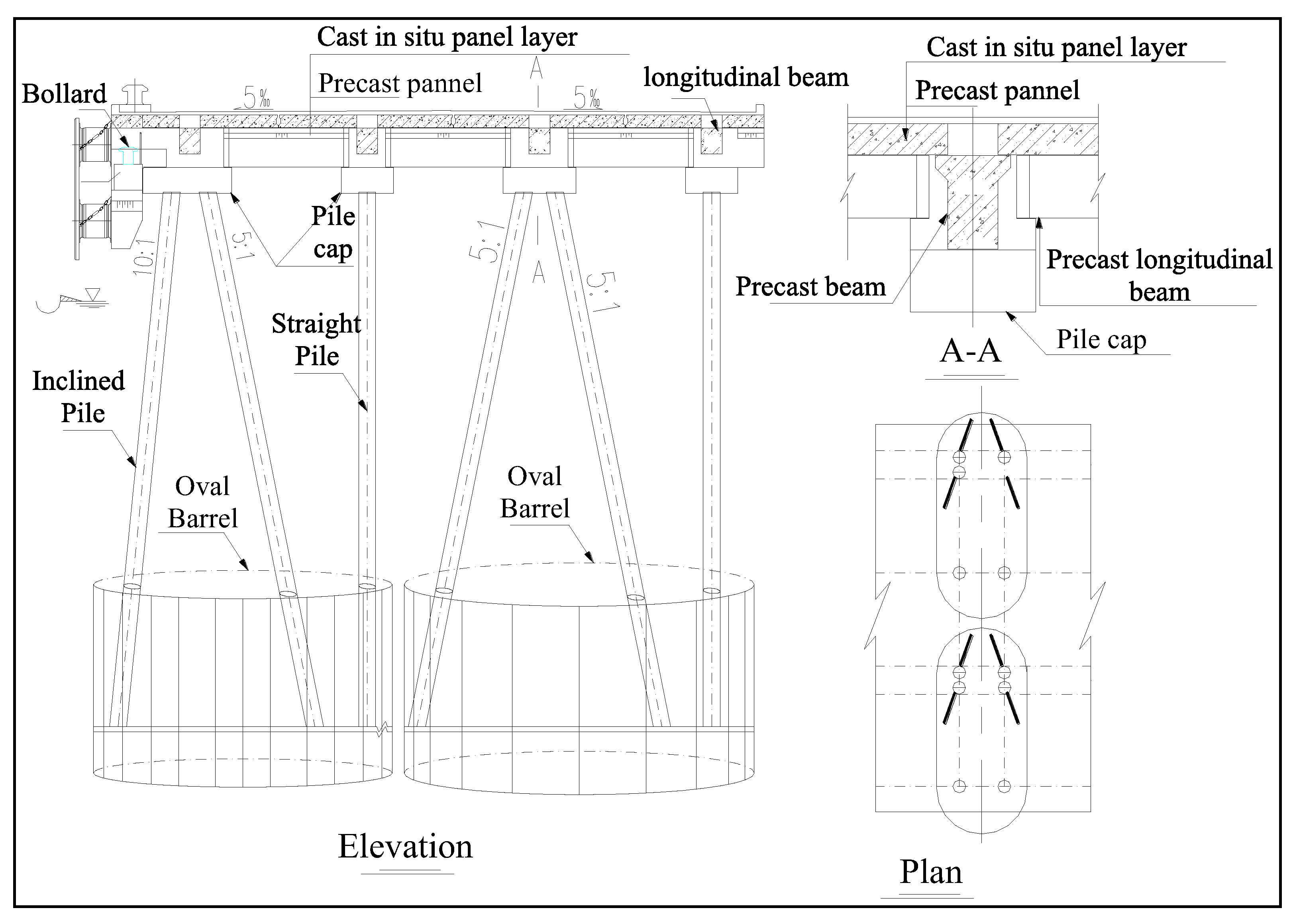
2], a pile foundation square caisson gravity structure, the new structure has the advantages of a coordinated structure, fast dispersion under the wave load, a wide range of applicable geological foundations, and a simple construction process, saving project progress and cost. Specifically: (1) the pile adopts the combination of straight piles and inclined piles, and the pile diameter ranges from ∅ 0.8 m to ∅ 2.5 m, so it can quickly disperse the external load and has little influence on wave reflection; (2) the box barrel foundation is a multibarrel combination type, and the top elevation is designed to be 1.25 times the incident wave height of the lowest tide level. The foundation treatment is simple and less affected by waves; (3) the new cylindrical foundation is prefabricated on land, with air floatation haulage, negative-pressure pumping sinking, and bottom installation. The upper high pile is reserved by the foundation and can be directly inserted. The construction process is simple; (4) the overall structure is flexible at the top and rigid at the bottom, which is suitable for different complex geological conditions.
Based on the deep-water wave impact environment in the open sea, the hollow pile foundation and bottom box foundation in the new structure have little impact, but the wharf superstructure is vulnerable to wave attack and serious damage due to the limitation of the wharf’s elevation. There have been a large number of cases of damage to structures located in unprotected sea areas due to the wave impact load [3]. For example, in 1972, the rise of water level and huge waves caused by Typhoon No. 3 destroyed the approach bridge decks of many wharves in North China. In September 2004, Hurricane Ivan hit Pensacola, Florida, in the USA, resulting in the collapse of the bridge deck of Escambia Bay Bridge [4]. In order to prevent such accidents, one must accurately calculate the crest height and panel wave impact force under extreme sea conditions, which can be used as the basic design data for reasonably determining the wharf elevation. At present, in the research field of wave crest height, the technical code for design and construction of an open wharf (JTJ295-2000) [5] stipulates that the wharf surface will not be submerged under the action of waves. Generally, it is considered that the beam and slab on the upper part of the wharf will not be affected by wave uplift force, and the water surface blocking height caused by the interaction between waves and the high-pile wharf is considered by using the surplus height, which is arbitrary. Hua Quan-li [6], for the two structures of vertical embankment wall and pile column, on the basis of the standard formula and in combination with the relationship between the dimensionless period of regular waves and relative water depth, derived the calculation formula and chart of the relationship between wave crest height and wave height, but test verification was not carried out. Rong Chuan-ya [7] used the second-order Stokes wave and elliptic cosine wave theory to calculate the crest surface elevation; the latter is more suitable for long-period action. Chen Guo-ping et al. [8] deduced the approximate analytical solution of wave crest height for the high-pile wharf structure according to the microamplitude wave theory and the conservation of wave energy flow, which was verified by a physical model test. Zhang Zhi-ming et al. [9] modified the coefficient in the theoretical formula by using the physical model test for a circular caisson pier wharf and deduced that it is suitable for single-pier, single-row pier, and double-row pier structures. Liu Chun-yang et al. [10] measured the reflection coefficient and fitted the calculation formula of wave crest height for the pile foundation gravity composite structure. The above research combined the physical model test and theoretical derivation and deduced a similar empirical calculation formula, as follows, through the undetermined coefficient K value method:
η ( k ) = h s + K i H
h s = π H 2 4 L c t a n h ( 2 π d L )
where η is the height of wave crests; K i is an undetermined coefficient; h s is the wave superelevation caused by wave nonlinearity; H is the wave height; L is the wavelength; and d is the water depth.
In the field of panel wave impact force research, in the early stages, a formula for the wave impact pressure on a panel was recommended in the harbor engineering design manual [11]. El Ghamry [12] and Wang [13] proposed p = γ h to describe the impact pressure, so the maximum impact pressure must appear near the static water surface, which is inconsistent with the experimental observation results. Yoshita [14], assuming that the pressure in the wave action area on a flat plate is uniformly distributed, gave the relationship between the wave impact pressure and the clearance between the trestle deck bottom and the water surface. Zhou Yi-ren et al. [15] proposed that the pressure on the plate can be divided into two forms, local impact type and uniform type, and obtained the respective calculation formulas. Song Ren et al. [16] obtained the improved wave impact pressure formula through a large number of tests and summaries by comparing the results of [11] and [14]. Recently, Lin Yue et al. [17] studied the structural time history dynamic response under wave action with ANSYS for the pile structure of an offshore LNG wharf, considering that the peak value of structural displacement and stress response caused by irregular waves was greater than 10–20% of regular waves and that the result of severe initial fluctuations could be abandoned. Zhang Shi-cao [18] studied the compression characteristics of a panel under the action of an extreme tsunami wave by using an ABAQUS simulation for the superstructure of a high-pile beam-slab wharf. It was concluded that the front end of the panel is subject to a large impact force at a vulnerable area. Shen Cai-hua et al. [19] established a three-dimensional dynamic response numerical model of a foundation pile superstructure and wave dynamic load for an offshore deep-water permeable-structure wharf. When the structure is impacted by waves, the internal force is the largest when the relative clearance is about 0.33, and the influence is the smallest when the relative clearance is about 0.50. Kuai Yan-rong [
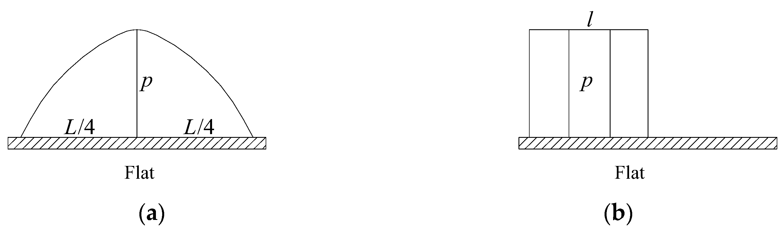
20] used the RANS equation and standard K-ε; according to the turbulence numerical model, when the wave incidence angle is 0°, the force on the front longitudinal and transverse beams is the largest. The calculation formulas obtained from the above research are more suitable for their respective conditions. The calculation formulas of wave uplift obtained by scholars can be roughly divided into two views: one is that the pressure on the plate is distributed according to the shape of the wave surface [11,12,13] (see Figure 1a), and the impact force on the plate can be calculated by Equation (3); the other is that, when the maximum impact pressure or uplift force occurs on the plate, the pressure on the plate is evenly distributed within a certain width [14,15,16,17,18,19,20] (see Figure 1b). However, the distribution width l assigned by different researchers is not the same. The calculated width of pressure l = L/4 is used by Goda, while Guo Da et al. believe l should be L/8–L/9, so the relationship between the total pressure value of wave supporting force and the set elevation of the trestle deck can be expressed as in Equations (4)–(5):
P = β γ B ( η 0 Δ h )  
P = ξ γ H L 4 B t a n h 2 π d L [ H Δ h 0 Δ h 0 H ]
Δ h 0 = Δ h π H 2 L c o t h ( 2 π d L )
where P is the wave impact force; β is the pressure response coefficient, which can be used when the width of the superstructure is less than 10 m ( β = 1.5 when the width of the superstructure is large, or 2.0 when it is not); Δ h is the superelevation; and η 0 is the height of the wave crest on still water, which is calculated by the second-order Stokes wave theory.
It can be seen that the above calculation methods of wave crest height and panel impact force have established corresponding empirical formulas for their respective structures and boundary conditions, and the formula forms are quite different. When applied to specific projects, under the applicable conditions of various formulas, their calculated values can differ by several times or even more than 10-fold under working conditions (when the bottom of the transparent structure panel is between a simple type of flat plate and a complex structure with longitudinal and transverse beams). The transparent structure is between offshore and shore; the wave action is between non-overtopping and overtopping of the transparent structure panel, etc. Based on the above analysis, because the factors affecting the wave impact force of the deck are very complex, the vertical and horizontal beam system, pile cap, and pile foundation under the deck of the new structure wharf may have a greater impact on the wave shape and air layer under the deck; this must be kept in mind in order to obtain a reasonable calculation method suitable for the wave crest height and impact force of the structure. By carrying out physical model tests and setting a series of test groups with the aim of fully understanding the characteristics of the wave impact process of the new structure wharf panel, this paper establishes the relationship between the wave crest height and impact force and each influence factor, puts forward a calculation method and empirical formula, and gives a determination method for the new surface elevation based on the calculation formula. This provides technical support for the popularization and application of new structure engineering.

2. Physical Model Test

2.1. Layout Type of Compound Structure Wharf

The new wharf adopts a double elliptical cylindrical foundation in the transverse direction (note: it can be adjusted to a single-cylinder type according to the actual situation of engineering geology and upper force conduction). The foundation adopts the single-barrel type, which means: (1) the length of the upper panel is less than 30 m; (2) the project is located in a large range of rock and other good bearing stratum geology. The high pile adopts a combination of inclined pile and straight pile; the upper structure adopts a combination of a transverse longitudinal beam and plate; and the mooring device is set at the end of the sea side. The specific layout of the plane and structural section is shown in Figure 2.

2.2. Determination of Test Conditions

According to the research objectives, in order to demonstrate the impact of different hydrodynamic and structural factors on wave crest elevation and wave impact force, the main influencing factors considered in the series group test design were: wave height Hs, period T ¯ , and superelevation Δ h (height from bottom of wharf surface to static water level).
The test set water level was d = 0.30 m; the incident angle of waves was normal incidence; an irregular wave height of Hs = 0.04 m, 0.05 m, 0.06 m, 0.07 m, 0.08 m, or 0.09 m was considered; average periods of T ¯ = 0.6 s, 0.8 s, 1.0 s, 1.2 s, 1.4 s, 1.6 s were used; and a wharf surface superelevation of Δ h = 0.01 m, 0.02 m, 0.03 m, 0.04 m, 0.05 m, 0.06 m, 0.07 m, 0.08 m, 0.09 m, or 0.10 m was considered. (Note: during the test, in order to ensure total reflection between the wave and the superstructure, each group of tests attempted to ensure that there was no overtopping on the wharf surface under the action of an incident wave. If overtopping occurred on the wharf surface under the combination of wave height and period, the next superelevation Δ h group test was carried out).

2.3. Test Design, Fabrication, and Method

2.3.1. Instruments and Equipment

Wave-making equipment: For independent research and development, the equipment was composed of a wave-making board, a servo driver, a servo motor, an encoder, a server, a computer, and its peripheral units. The wave-making principle is as follows: according to certain parameters corresponding to the waves required for the test, the computer completes the calculation of the wave-making control signal and transmits the wave-making control signal to the servo driver through the interface circuit, the servo driver controls the rotation of the servo motor, and the electric cylinder converts the rotation of the output shaft of the servo motor into the linear movement of the push rod of the electric cylinder. The motion is transmitted to the wave-pushing plate through the lever mechanism to drive the wave-pushing plate to produce the desired water wave. Regarding wave-making capacity, the maximum wave-making water depth is 0.7 m, the wave height is 0–0.3 m, the period is 0.5–5.0 s, and 180° multidirectional wave-making can be realized.
Measuring equipment: (1) For wave height measurement, we used a self-developed tk2008 dynamic wave height test system, which uses capacitive sensors to measure waves, automatically collect the wave surface process, and assemble statistics on the process through the up-crossing zero point method to obtain the desired wave height and period. (2) The measurement of wave impact force was carried out using a self-developed total force test system. It was composed of a six-axis functional total force sensor with coupling output (model 3712b), measuring the frame, upper and lower pulleys, and dynamic acquisition system. The measurement ranges of total force sensors in the X, Y, and Z directions are 0–800 N, 0–800 N, and 0–2500 N, respectively. The system automatically completed the calibration and processing functions.

2.3.2. Model Design and Production

The model test harbor basin was 40.0 m wide and 45.0 m long. In order to reduce the reflection of the wave boundary, wave eliminators were set around the harbor basin. According to the relevant provisions of the technical code for simulation tests of water transportation engineering (JTS/T231-2021) [21] and the research purpose, we adopted the normal model, which was designed according to the similarity law of the Froude number. The model test basin had a flat bottom. The simulated total length of the wharf model with the compound structure was 10.0 m, the width was 0.42 m, and the middle 0.50 m was the test section. The wharf superstructure model of this section was made of acrylic material, and the pile used a hard PVC pipe. The model of this section was the length of two bent frames of the prototype (see Figure 3). The oval box barrel of the foundation at the bottom of the wharf was prefabricated with concrete in advance, and the corresponding pile position holes were reserved according to the pile location. During installation, the foundation and bottom of the harbor basin were fixed by hinges to ensure sufficient stiffness under wave impact. The wharf apron was a berthing component, and the effect of model fabrication was as shown in Figure 3.

2.3.3. Test Method

Wave simulation: Irregular waves were used in the test, and the wave spectrum was a JONSWAP spectrum ( γ = 3.3 ). The intermittent wave generation method was adopted in the test to eliminate the multiple reflections of waves. The duration of each group of irregular waves was about 1.5–4.0 min, and the wave number was about 120–150. Then we stopped the machine, continuing with the next group of tests when the water surface was calm. Each group of tests was repeated 3 times, and the wave height and periodic error were controlled within the ±2% allowed by the specification.
Wave height measurement at wharf front: Multiple wave height sensors were arranged at the front of the test section, and wave height sensors were also arranged at the traveling wave position for monitoring. See Figure 3 for the layout of measuring points.
Measurement of panel wave impact force: A total tension and compression force sensor measurement device was adopted, and the measured sample data were automatically collected, processed, and analyzed by the computer, and the sampling frequency is 100 Hz. The direction of the total wave force on the structure is defined as follows: (1) when the force is the same as the wave propagation direction, it is defined as the horizontal force, and when the force direction is the same as the wave propagation direction, it is set as positive, otherwise it is negative; When the force is perpendicular to the wave propagation direction, it is defined as the vertical impact force, and the force direction is positive upward, otherwise it is negative.

3. Results

3.1. Test Results and Analysis

According to the test, when the traveling wave is about to impact the panel when superelevation Δ h is small, the front wave surface of the wharf panel rises first, and the rear drops. The wave first hits the pile cap at the front end and then hits the panel. When the wave surface rises to the highest level, almost all of the lower part of the panel is submerged by water to form a reflected wave. Then, the wave surface begins to fall, and the second impact is about to be launched; along with the increase in Δ h , the blocking effect of the superstructure on the wave height decreases, and the waves directly impact the middle of the panel, resulting in wave breaking. When Δ h increases again, the wave fails to impact the panel and finally forms a transmitted wave. The wave crest height in front of the wharf is mainly caused by the superposition of the reflected wave and incident wave caused by a superstructure such as the front longitudinal beam, pile cap, or berthing components, resulting in water surface blocking height. However, the pile column spacing of the wharf structure is large, which has a minor impact on the wave crest height in front of the wharf. The test results of wave crest height and panel impact force under each test condition are shown in Table 1. The results also reflect the above test phenomena.

3.2. Calculation Method of Wave Crest Height and Panel Impact Force

Based on the above series of test results, in order to facilitate the popularization and application of new structure engineering, calculation methods for wave crest height and panel impact force are proposed to provide basic data for engineering design.

3.2.1. Calculation Method of Wave Crest Height

It can be seen from the results in Table 1 that the superelevation Δ h is directly related to the backwater height of the water body at the wharf apron, so Δ h is an important factor affecting the crest height—that is, the crest height is directly proportional to the reflected wave height of the superstructure of the wharf (such as the first row of the longitudinal beam, pile cap, and berthing components). At the same time, incident wave height, period, and water depth are also important factors of wave crest height and are also in positive proportion. Therefore, the relationship between the wave crest height and influencing factors (reflection coefficient and relative superelevation) is established via the relationship between Δ h / H i and wave steepness ( H i / L ) and can be obtained by using the method of dimensional analysis as follows:
η = f ( ( 1 + K r ) Δ h / H i , H i / L )
R = 1 T 0 T l η ρ g . A . c o s h [ k ( d + z ) ] cosh ( k d ) 2 π T c o s h [ k ( d + z ) ] sinh ( k d ) c o s 2 ( k x σ t ) d z d t
K r = s i n h [ 2 k ( d + η 0 ) ] s i n h [ 2 k ( d l ) ] + 2 k ( η 0 + l ) 2 k d + s i n h ( 2 k d )
η 0 = H i 2 + π H i 2 2 L [ ( c h 4 π d L + 2 ) c h 2 π d L 4 ( s h 2 π d L ) 3 ]
where η is the crest elevation and K r is the reflection coefficient. Based on the conservation of wave energy flow [22] and the research in [8], each bent can be generalized as a vertical rectangular baffle with an equivalent area. At the same time, the water entry depth of the baffle is   l (positive when the lower edge of the baffle is underwater). This part of the wave energy flow is blocked and cannot be transmitted, which will form a reflected wave height. It is assumed that the reflected wave energy is equal to the incident wave energy on the vertical baffle. K r is obtained by integrating the average wave energy flow in one cycle R of the analytical solution; A is the amplitude (for a regular wave, A = H / 2 ); d is the water depth; ρ is the density of water; g is gravitational acceleration; z is the distance between the water quality point and the clean water surface; the coordinate origin is located on the clean water surface; the coordinate upward is positive; k is the wave number, k = 2 π / L ; L is the wavelength; σ is the wave angle frequency σ = 2 π / T ; and T is the period. η 0 is the maximum height of the incident wave surface from the stillwater surface, which can be calculated by the second-order Stokes wave theory; H i is the incident wave height.
To obtain the change rule of crest height η and influencing factors, we set a certain wave steepness H i / L , change ( 1 + K r ) Δ h / H i , and we investigated the change rule of ( 1 + K r ) Δ h / H i and η (see Figure 4). It can be seen from Figure 4 that, under the condition of H i / L , we obtained the relationship of ( 1 + K r ) Δ h / H i ; η is linear, and the slope of the change trend is basically the same, so it can be considered that ( 1 + K r ) Δ h / H i and η is linear.
We also set certain values of Δ h / H i and change wave steepness, H i / L , and we investigated the change rule of H i / L and η (see Figure 5). It can be seen from Figure 5 that wave steepness H i / L and η also show linear changes, but the slope of the change trend is basically zero. Therefore, it is considered that the influence of crest height is small and can be ignored.
To sum up, for Equation (6), only ( 1 + K r ) Δ h / H i is considered between the height of wave crest and each influence factor for its influence, the least-squares method is used to linearly fit the data, and the fitting empirical formula is derived as follows:
η = 12.75 ( 1 + K r ) Δ h H i 0.56

3.2.2. Calculation Method of Panel Wave Impact Force

The calculation method is the same as that proposed for the wave crest height, which is affected by the transverse longitudinal beam under the panel. Therefore, based on the above analysis of the influence factors of the wave crest height, the effects of the wave surface impact angle, air layer, and wave force were introduced, and the following functional relationship of the maximum impact force of the surface plate was obtained by using the method of dimensional analysis:
f ( P γ H i , H i L , d L , B H i , Δ h H ) = 0
In order to obtain the change relationship between the total impact force P and each influence factor, the change relationship diagram between the impact force and each influence factor was drawn according to the test results. Then, the physical quantities, such as each influence factor, were fitted.
Influence of change relationship of relative superelevation Δ h / H and P / γ H i : The change of the relationship between the two is shown in Figure 6. According to the change results in Figure 6, when the wave steepness H / L is near 0.04, the impact force is the largest—that is, the relative superelevation Δ h H = 0.4 0.5 , the front wharf panel is of flat plate type Δ h H = 0.2 0.4 , affected by the longitudinal beam—in terms of wave impact angle, the greater the relative superelevation, the greater the influence of the air layer. On the other hand, the larger the relative superelevation, the larger the space between the wave and the transverse beam, the longer the wave surface rises to the panel, and the greater the possibility of air escape. It can be seen that, compared with a horizontal plate on a still water surface, under the same impact angle and rising speed, the impact pressure on the plate at a relatively high altitude must be greater. However, the increase in superelevation will inevitably reduce the rising velocity of the wave surface and reduce the impact pressure.
Influence of change relationship of wave steepness H / L and   P / γ H i : The change in the relationship between the two is shown in Figure 7. It can be seen from the figure that the greater the wave steepness, the smaller the impact force, which is in inverse proportion. It also shows that the effect of wave height is more intense than that of the period. When the wave grows, the rising velocity of the wave surface will be greatly reduced, and the maximum impact force will be reduced.
Influence of change relationship of wave steepness B / H and   P / γ H i : The change in the relationship between the two is shown in Figure 8. Since only one fixed plate with a width of 0.42 m was used in the test, the change relationship was obtained by changing the incident wave height. It can be seen from the figure that the impact force has a parabolic relationship—that is, it first increased and then decreased, which is consistent with the superelevation Δ h . The plate width is 5–8 times the wave height, which has the greatest impact. For a part that is too wide (B > 8.0 H) or too narrow (B < 5.0 H), the wave has little impact.
Influence of change relationship of Wave steepness d / L and   P / γ H i : The change of the relationship between the two is shown in Figure 9. Similarly, only one water depth of 0.30 m was carried out in the test, so the change relationship was obtained by changing the incident wave period. It can be seen from the figure that the impact force showed a parabolic relationship; that is, it increased first and then decreased. The period was 1.0 s, and the impact force of the panel was the largest. Compared with other influencing factors, the overall change trend was weak, especially in its long period; the impact force had little change.
Due to the interaction between various factors, they cannot be considered separately. Therefore, in this study, the wave steepness H / L and relative superelevation Δ h / H take two exponential function relations, which are considered together. At the same time, the influence of the transverse and longitudinal beam structure, plate width, and water depth is calculated by introducing the coefficient calculation method. According to the analysis of the variation relationship between the above impact force and various influencing factors, and using the multiple linear regression method to determine the coefficients of various physical parameter terms, the following equations for the maximum impact force of the wave uplift force of the new barrel-pile foundation compound structure wharf, reflecting various influencing factors, can be used:
P X γ H = K 1 ( 1 Δ h η ) 0.75 e x p [ K 2 ( Δ h H 0.16 ) 2.86 ]  
X = L 4 ( 1.3 Δ h H ) 2  
K 1 = 0.93 K 2 e x p [ 155 K 2 ( H L 0.042 ) 2 ]  
K 2 = 4.0 t a n h ( B 2.2 H ) 3 / 2 t a n h ( 2 π d L )  
where P is the maximum impact force of the wharf panel; η can be obtained from Equation (10) above; X is the representative width of the impact in the wave propagation direction, which can be obtained from Equation (13); when the calculated value of X is greater than plate width b, X = B ; k1 is the impact coefficient of the transverse longitudinal beam under the wharf, which can be obtained from Equation (14); and K 2 is the impact coefficient of the plate width and water depth, which can be obtained from Equation (15).

3.3. Determination Method of New Structure Wharf Elevation

Wave force is often the control load of beam slab structure and even pile foundation structure design. If the bottom elevation of these superstructures of a high-pile wharf is low, under bad sea conditions, when large waves pass under and make contact with the panel, it will have a great impact on the wharf structure, and it is very easy to cause instability. In this regard, combined with the previous relevant research, Zhu Li-xiang [23] aimed to design the top elevation of the wharf apron of a pile foundation, and Gao Peng [24] aimed for a research method of the surface elevation of the harbor wharf in the form of a high-pile beam slab structure. The method for determining the elevation of the new structure wharf is proposed as follows: (1) when the wharf is not in the water, the wharf surface elevation E = η (the maximum crest height) + DHWL (design high water level), where η can be calculated according to Equation (10); (2) when the wharf is in water, it can be calculated according to Equations (12)–(15) for the wave impact force of the wharf panel and determined in combination with the structural reinforcement strength; (3) when the wave is broken or the impact force is large, it is recommended to verify this using the physical model.

4. Discussion

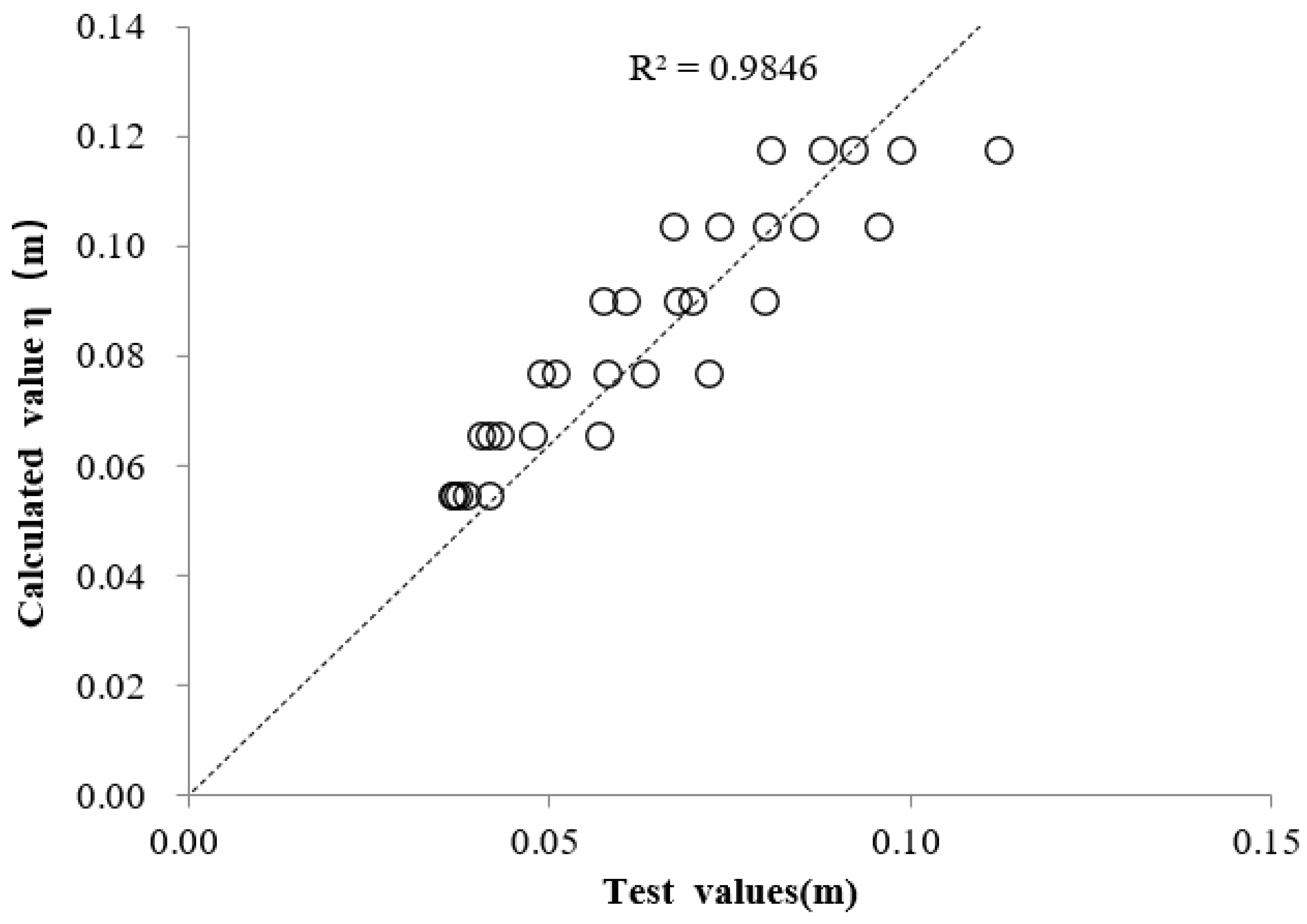
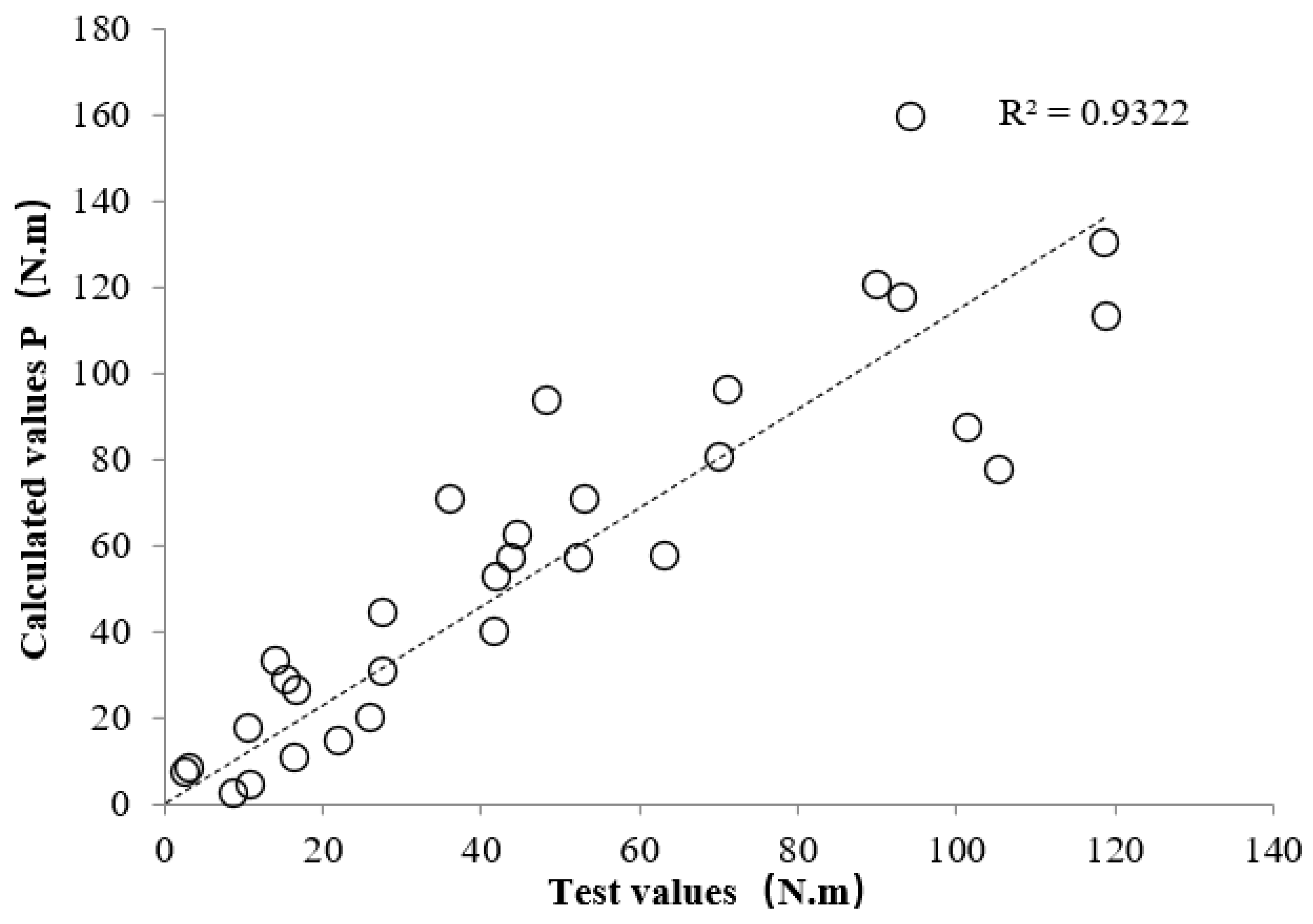
In order to verify the rationality of the calculation formulae, Figure 10 and Figure 11 show the comparison between the wave crest height and the impact force test value and the calculated value, respectively. The results in Figure 10 show that the correlation coefficient between the test value and the calculated value of the wave crest height is 0.893. The main reason for the analysis is the reflection coefficient K r ’s analytical solution; the actual wave will break and not fully reflect after impacting the transverse longitudinal beam, which deviates from the assumption. According to Figure 11, the correlation coefficient between the calculated value of panel impact force and the test value is 0.80. The reasons for the dispersion of the two are mainly the contingency of maximum impact and the complexity of influencing factors, especially the influence of relative superelevation, and the slight change of transverse and longitudinal beam elevation, which may cause a deviation of the maximum impact pressure. At the same time, due to the limited number of test groups, different transverse and longitudinal beam structural types, as well as complex conditions such as traveling waves breaking and waves crossing the wharf surface, it is recommended to verify this using the physical model.
According to the design analysis of the new tubular-pile foundation composite wharf structure to be applied in the future, based on the wave height near the static water level, the top of the box barrel foundation can be designed to be more than 10 m away from the static water level, so the impact of the wave is small. In addition, the upper part is the pile foundation structure, which has little reflection on the wave; by improving the berthing conditions of the wharf and reducing the wharf elevation from the perspective of project cost, the new composite structure will be the main development trend of open wharf design in the future.

5. Conclusions

This paper is based on the fact that, in recent years, with the depletion of natural coastline, offshore deep water is likely to be the development direction of large-scale port and wharf construction in the future. To cope with the conditions of big waves and strong currents in the open sea, a new type of tubular-pile foundation composite wharf structure is proposed.
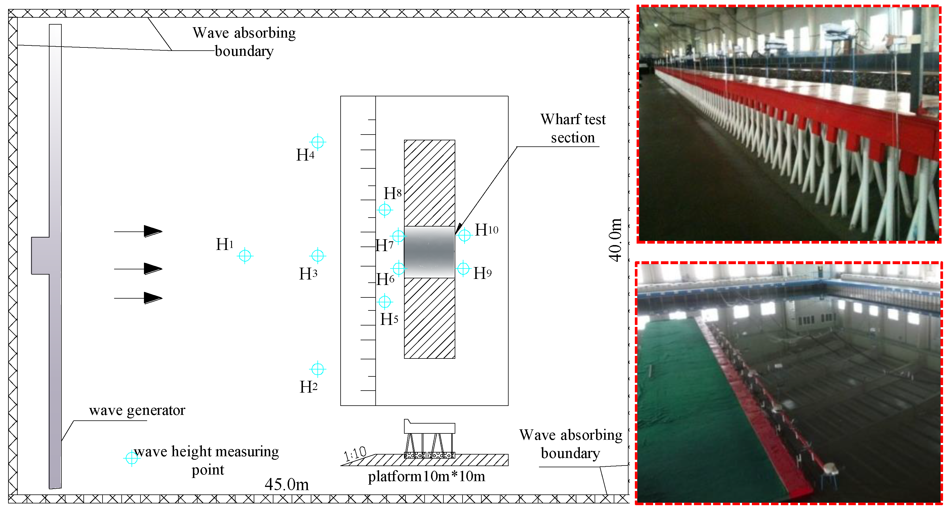
A series of groups involving multiple influencing factors such as wave height, period, superelevation, and water level are designed by means of physical model tests. The research results reveal the wave action characteristics of the new structure. Based on the traditional calculation methods of wave crest height and panel impact force of the structure, a new structure calculation method is proposed, and a simple calculation formula is obtained. Comparing the calculated values with the measured values, the correlation between the two results is more than 0.80, and the accuracy is generally good, which provides basic data for the engineering design. According to the wave crest height and panel impact test results, the determination method of the wharf surface elevation of the new structure is put forward as follows: (1) when the wharf is not in the water, the wharf surface elevation E = η (the maximum crest height) + DHWL (design high water level), where η can be calculated according to Equation (10); (2) when the wharf is in water, it can be calculated according to Equations (12)–(15) for the wave impact force of the wharf panel and determined in combination with the structural reinforcement strength; (3) when the wave is broken, or the impact force is large, it is recommended to verify this using the physical model.

Author Contributions

L.G.: data collection, model design and testing, and data analysis; H.C.: data processing, comparison, and analysis; S.C.: model testing, data processing, comparison and analysis, and verification; H.L.: series group model testing, test instrument debugging, test terrain processing, and data verification. All authors have read and agreed to the published version of the manuscript.

Funding

This study was financially supported by the National Natural Science Foundation of China (52001149) special fund for central scientific research institutes (TKS2021010).

Data Availability Statement

Data sharing is applicable to this article, as new data were created or analyzed in this study.

Acknowledgments

This physical model test was conducted in the experimental harbor basin of the Tianjin Research Institute for Water Transport Engineering.

Conflicts of Interest

The authors declare no competing interests. The corresponding author is responsible for submitting a competing interest statement on behalf of all authors of the paper.

References

  1. Chen, Y.; Sun, X. Instability analysis of a new type of tubular open wharf structure. Waterway Port. 2019, 2, 176–181. [Google Scholar] [CrossRef]
  2. Wang, W.J. Application of Pile Foundation Gravity Composite Structure in Deep Water Wharf. Master’s Thesis, Dalian University of Technology, Dalian, China, 2016. [Google Scholar]
  3. Guo, D.; Cai, B.H. Calculation of wave uplift force of transparent building panel. J. East China Inst. Water Res. 1980, 1, 14–33. [Google Scholar]
  4. Sheppard, D.M.; Rena, R. Preliminary Forensic Investigation of Damage at the I-10 Bridge over Escambia Bay during Hurricane Ivan; Ocean Engineering Associates, Inc.: Gainesville, FL, USA, 2004. [Google Scholar]
  5. Ministry of Transport. Technical Specification for Design and Construction of Open Wharf; People’s Communications Publishing House Co., Ltd: Beijing, China, 2000. [Google Scholar]
  6. Hua, Q.L. Analysis and calculation of wave crest height acting on vertical embankment wall and pile. Water Res. Plan. Des. 2020, 1, 117–123. [Google Scholar] [CrossRef]
  7. Rong, C.Y.; Hao, X.Y. Application of elliptic cosine wave theory in calculation of rising height of wave crests. Port. Waterway Eng. 2017, 10, 86–89, 95. [Google Scholar] [CrossRef]
  8. Chen, G.P.; Zhang, Z.M.; Yan, S.C. Study on wave crest height in front of high column Wharf under wave action. Water Trans. Eng. 2010, 1, 28–30. [Google Scholar] [CrossRef]
  9. Zhang, Z.M.; Zhu, X.S.; Zhou, F. Study on the height of wave crest in front of large open circular caisson pier Wharf under wave action. China Harbor Construct. 2011, 174, 20–26. [Google Scholar] [CrossRef]
  10. Liu, C.Y.; Zhang, P.C. Study on reflection coefficient and wave crest height of pile foundation gravity composite structure wharf. China Water Trans. 2012, 12, 240–242. [Google Scholar] [CrossRef]
  11. CCCC First Navigation Engineering Survey and Design Co., Ltd. The First Navigation Engineering Survey and Design Institute of the Ministry of Communications Harbor Engineering Design Manual (Middle), 2nd ed.; People’s Communications Press: Beijing, China, 1994. [Google Scholar]
  12. El Ghamry, O.S. Wave Forces on a Dock; Technical Report HEL-9-1; University of California, Institute of Engineering Research: Berkeley, CA, USA, 1963. [Google Scholar]
  13. Wang, H. Water wave pressure on horizontal plate. J. Hydraul. Div. 1970, 96, 1997–2017. [Google Scholar] [CrossRef]
  14. Goda. Summer Workshop on Water Engineering, 2nd ed.; Coast Port Coco: Tokyo, Japan, 1967. [Google Scholar]
  15. Zhou, Y.R.; Chen, G.P.; Huang, H.L. Distribution of wave uplift force on permeable horizontal plate. Ocean Eng. 2003, 2, 41–47. [Google Scholar] [CrossRef]
  16. Song, R.; Bai, L.X. Effect of waves on superstructure of offshore open wharf. Port Eng. Technol. 1997, 4, 1–9. [Google Scholar]
  17. Lin, Y.; Cao, D.L. Time-history dynamic analysis on the wave-induced high-piled pier structure. Port Waterway Eng. 2019, 8, 74–77, 88. [Google Scholar] [CrossRef]
  18. Zhang, S.C. Analysis of compression characteristics of superstructure of high pile beam slab Wharf under tsunami wave. Sci. Technol. Innov. Inf. 2021, 24, 144–145. [Google Scholar] [CrossRef]
  19. Shen, C.H.; Xie, F. Influence of wave force on damage of offshore deep water wharfs on the top elevation. Port Waterway Eng. 2018, 9, 59–65, 75. [Google Scholar] [CrossRef]
  20. Kuai, Y.R.; Qi, M.L.; Li, J.Z. Analysis of wave forces on bridge substructure in near-shore. J. Zhejiang Univ. Eng. Sci. 2018, 52, 2356–2364. [Google Scholar]
  21. Ministry of Transport. Technical Code for Simulation Test of Water Transportation Engineering; People’s Communications Publishing House Co., Ltd: Beijing, China, 2021. [Google Scholar]
  22. Yan, K.; Liang, Q.X. Coastal Engineering, 1st ed.; Yan, A., Hao, Y.J., Eds.; Ocean Press: Beijing, China, 2002. [Google Scholar]
  23. Zhu, L.; Sun, Y.G.; Gu, W.Q. Design methods of top elevation of piled wharf. China Harbour Eng. 2017, 37, 72–76. [Google Scholar] [CrossRef]
  24. Huang, R.Y.; Tao, R.; Feng, X.D. Elevation design of temporary clip for pile supported wharf under strong wave condition. Port Waterway Eng. 2019, 12, 39–43, 64. [Google Scholar] [CrossRef]
Figure 1. (a) Wave surface type wave impact force distribution and (b) uniform wave impact force distribution.
Applsci 12 01060 g001
Figure 2. Structural section of compound wharf.
Applsci 12 01060 g002
Figure 3. Model layout.
Applsci 12 01060 g003
Figure 4. ( 1 + K r ) Δ h / H i and η change relationship.
Applsci 12 01060 g004
Figure 5. H i / L and η change relationship.
Applsci 12 01060 g005
Figure 6. Δ h / H i and P / γ H i change relationship.
Applsci 12 01060 g006
Figure 7. H / L and P / γ H i change relationship.
Applsci 12 01060 g007
Figure 8. B / H and P / γ H i change relationship.
Applsci 12 01060 g008
Figure 9. d / L and P / γ H i change relationship.
Applsci 12 01060 g009
Figure 10. Comparison of test values and calculated values of wave crest height at wharf apron.
Applsci 12 01060 g010
Figure 11. Comparison of test values and calculated values of wharf panel impact force.
Applsci 12 01060 g011
Table 1. Test results of wave crest height and panel impact force.
Test Conditions Δ h   ( m ) η   ( m ) P (N/m)Test Conditions Δ h   ( m ) η   ( m ) P (N/m)
Hs = 0.09   m ,   T   ¯ = 1.6 s0.100.08610.94 Hs = 0.06   m ,   T ¯ = 1.0 s0.060.05416.53
0.090.08927.600.050.05641.76
0.080.09736.080.040.06463.32
0.070.10248.490.030.070105.64
0.060.10990.160.020.080101.67
0.050.11694.28///
Hs = 0.08   m ,   T ¯ = 1.4 s0.090.0698.83 Hs = 0.05   m ,   T   ¯ = 0.8 s0.050.0453.28
0.080.07426.110.040.04615.43
0.070.08144.760.030.04827.68
0.060.08970.210.020.05352.46
0.050.09493.290.010.06344.03
0.040.106118.81///
Hs = 0.07   m ,   T ¯ = 1.2 s0.070.06322.03 Hs = 0.04   m ,   T ¯   = 0.6 s0.040.0402.62
0.060.06741.970.030.04210.61
0.050.07553.130.020.04316.82
0.040.07771.290.010.04614.09
0.030.088118.96///
Publisher’s Note: MDPI stays neutral with regard to jurisdictional claims in published maps and institutional affiliations.

